

Page 1

®
®
Instruction Manual
Page 2
NOTICE
All instructions, warranties and other collateral documents are subject to change at the sole discretion of Horizon Hobby, Inc. For up-to-date product literature, visit
horizonhobby.com and click on the support tab for this product.
Meaning of Special Language
The following terms are used throughout the product literature to indicate various levels of potential harm when operating this product:
NOTICE: Procedures, which if not properly followed, create a possibility of physical property damage AND a little or no possibility of injury.
CAUTION: Procedures, which if not properly followed, create the probability of physical property damage AND a possibility of serious injury.
WARNING: Procedures, which if not properly followed, create the probability of property damage, collateral damage, and serious injury OR create a high prob-
ability of superfi cial injury.
WARNING: Read the ENTIRE instruction manual to become familiar with the features of the product before operating. Failure to operate the product
correctly can result in damage to the product, personal property and cause serious injury.
This is a sophisticated hobby product. It must be operated with caution and common sense and requires some basic mechanical ability. Failure to operate this
Product in a safe and responsible manner could result in injury or damage to the product or other property. This product is not intended for use by children without
direct adult supervision. Do not use with incompatible components or alter this product in any way outside of the instructions provided by Horizon Hobby, Inc. This
manual contains instructions for safety, operation and maintenance. It is essential to read and follow all the instructions and warnings in the manual, prior to assembly, setup or use, in order to operate correctly and avoid damage or serious injury.
Age Recommendation: Not for children under 14 years. This is not a toy.
General Safety Precautions and Warnings
• Always keep a safe distance in all directions around your model to avoid collisions or injury. This model is controlled by a radio signal subject to interference
from many sources outside your control. Interference can cause momentary
loss of control.
• Always operate your model in open spaces away from full-size vehicles, traffi c
and people.
• Always carefully follow the directions and warnings for this and any optional
support equipment (chargers, rechargeable battery packs, etc.).
• Always keep all chemicals, small parts and anything electrical out of the reach
of children.
• Always avoid water exposure to all equipment not specifi cally designed and
protected for this purpose. Moisture causes damage to electronics.
• Never place any portion of the model in your mouth as it could cause serious
injury or even death.
CAUTION: The ESCs for the 350 QX are not compatible with any other product, and the 350 QX is not compatible with any other ESCs. Use of any other
ESCs on the 350 QX will cause a crash, which may result in property damage and/or personal injury.
WARNING AGAINST COUNTERFEIT PRODUCTS: If you ever need to replace a Spektrum component found in a Horizon Hobby product, always purchase
from Horizon Hobby, Inc. or a Horizon Hobby authorized dealer to ensure authentic high-quality Spektrum product. Horizon Hobby, Inc. disclaims all support
and warranty with regards, but not limited to, compatibility and performance of counterfeit products or products claiming compatibility with DSM or Spektrum.
• Never operate your model with low transmitter batteries.
• Always keep aircraft in sight and under control.
• Always move the throttle fully down at rotor strike.
• Always use fully charged batteries.
• Always keep transmitter powered on while aircraft is powered.
• Always remove batteries before disassembly
• Always keep moving parts clean.
• Always keep parts dry.
• Always let parts cool after use before touching.
• Always remove batteries after use.
• Never operate aircraft with damaged wiring.
• Never touch moving parts.
EN
2
Page 3
®
hank you for purchasing the Blade 350 QX quadcopter. You are in
T
for an exciting experience with this exceptional fl ying machine. With
GPS, pressure and compass sensors added to the SAFE™ (Sensor
Assisted Flight Envelope) system, the 350 QX has some incredible
features. Position hold, altitude command and self-leveling provide you
with a smooth and manageable fl ight performance. With the addition of
the SAFE Circle™, Stick Relativity and Return Home functions, the 350
Table of Contents
Box Contents ......................................................................................................4
Charging Warnings..............................................................................................4
Low Voltage Cutoff (LVC) .....................................................................................4
Charging the Flightline Battery ............................................................................4
Mounting a Camera ............................................................................................5
Transmitter Setup (BNF) ......................................................................................6
Transmitter Control Layout (RTF) .........................................................................7
Connecting the Flight Battery ..............................................................................7
Binding ...............................................................................................................8
Flight Mode Switches..........................................................................................9
Flight Modes Explained .......................................................................................9
Audible Alerts and LED Codes ...........................................................................10
GPS Functionality of the 350 QX ........................................................................12
Flight Guidelines and Warnings .........................................................................12
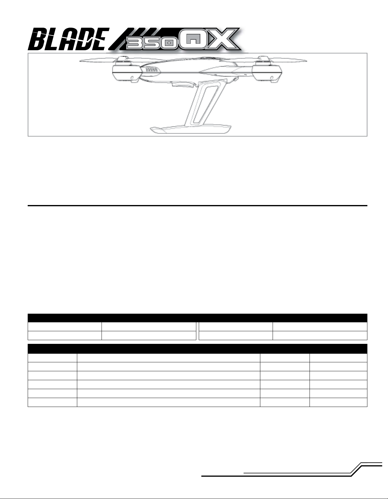
Blade 350 QX Specifi cations
Length
Height
18.30 in (465mm)
5.43 in (138mm)
QX makes it more practical and easier to fl y for new pilots without RC
experience. The Blade 350 QX uses LED codes to communicate fl ight
modes, GPS functions and errors for which you will need the manual. To
assure you have a safe and fun experience with your new quadcopter, it
is critical that you take the time to read and understand this manual and
all the features this aircraft contains.
Preparing the 350 QX for Flight .........................................................................13
Flying the 350 QX .............................................................................................13
Airframe Maintenance.......................................................................................15
Compass Calibration .........................................................................................16
Pressure Sensor Calibration ..............................................................................16
Accelerometer Calibration .................................................................................16
ESC and Motor Assignment Procedure ..............................................................17
Troubleshooting ................................................................................................17
Limited Warranty ..............................................................................................18
Warranty and Service Contact Information ........................................................18
FCC Information ................................................................................................19
IC Information ...................................................................................................19
Compliance Information for the European Union ................................................19
Main Rotor Diameter
Flying Weight
22.80 in (580mm)
24 oz (680 g)
Airframe
Motors
ESCs
Battery
Charger
Transmitter
Component RTF BNF
Blade 350 QX Quadcopter included included
4x Brushless Outrunner Motor, 1100Kv installed installed
4x 10-Amp Brushless ESC installed installed
3S 11.1V 2200mAh 30C Li-Po included included
2–3S Li-Po Balancing DC Charger, 0.5–3A included included
DSM2®/DSMX® compatible transmitter included required
To register your product online, visit www.bladehelis.com
3
EN
Page 4
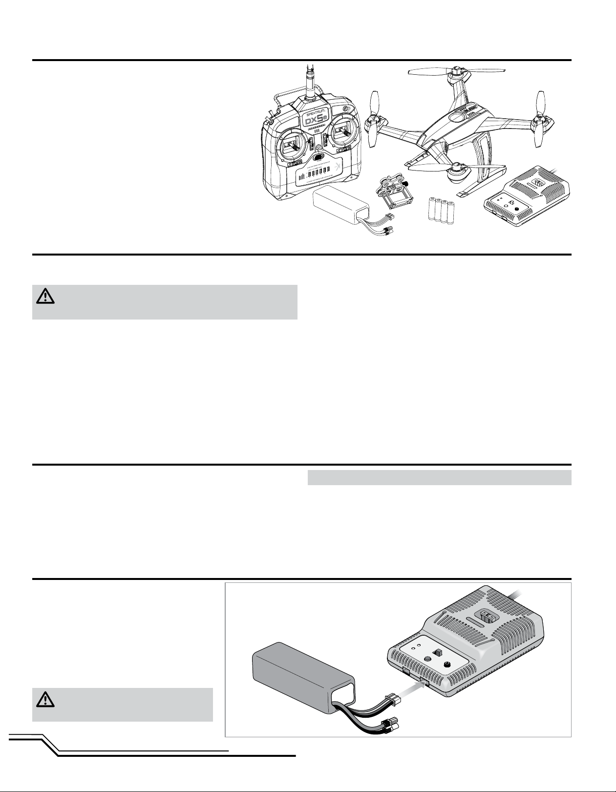
Box Contents
• Blade 350 QX
• Camera Mount
• 3S 11.1V 2200mAh Li-Po Battery Pack
• 2–3S DC Li-Po Balancing Charger
• DX5e DSMX 5-Channel Transmitter (RTF only)
• 4 AA Batteries (RTF only)
Charging Warnings
The Battery Charger (EFLC3010) included with your quadcopter has been
designed to safely charge the Li-Po battery.
CAUTION: All instructions and warnings must be followed exactly.
Mishandling of Li-Po batteries can result in a fi re, personal injury and/or
property damage.
• By handling, charging or using the included Li-Po battery, you assume all risks
associated with lithium batteries.
• If at any time the battery begins to balloon or swell, discontinue use immediately. If charging or discharging, discontinue and disconnect. Continuing to
use, charge or discharge a battery that is ballooning or swelling can result in
fi re.
• Always store the battery at room temperature in a dry area for best results.
• Always transport or temporarily store the battery in a temperature range of
40–120º F (5–49° C). Do not store battery or model in a car or direct sunlight.
If stored in a hot car, the battery can be damaged or even catch fi re.
• Always charge batteries away from fl ammable materials.
Low Voltage Cuto (LVC)
Low voltage cutoff (LVC) protects the Li-Po battery from over-discharge in fl ight
and activates when the battery reaches a preset value. When the battery is
discharged to the cutoff point, the aircraft will display rapidly fl ashing red, green
and blue LEDs to warn you it’s time to land. When you see this LED code, land
immediately to prevent over-discharge and damage to the battery.
When the LVC is activated, you have approximately 2 minutes until the battery is
depleted and can no longer maintain a hover. Repeated fl ying to LVC will damage
the battery.
• Always inspect the battery before charging
• Always disconnect the battery after charging, and let the charger cool between
charges.
• Always constantly monitor the temperature of the battery pack while charging.
• ONLY USE A CHARGER SPECIFICALLY DESIGNED TO CHARGE LI-PO BATTERIES. Failure to charge the battery with a compatible charger may cause a fi re
resulting in personal injury and/or property damage.
• Never discharge Li-Po cells to below 3V under load.
• Never cover warning labels with hook and loop strips.
• Never leave charging batteries unattended.
• Never charge batteries outside recommended levels.
• Never charge damaged batteries.
• Never attempt to dismantle or alter the charger.
• Never allow minors to charge battery packs.
• Never charge batteries in extremely hot or cold places
(recommended between 40–120° F) or (5–49° C) or place in direct sunlight.
NOTICE: Crash damage and battery damage are not covered under warranty.
IMPORTANT: Always disconnect and remove the Li-Po battery from the aircraft
after each fl ight. Charge your Li-Po battery to about half capacity before storage.
During storage, make sure the battery charge does not fall below 3V per cell.
A connected battery will result in trickle discharge.
Charging the Flight Battery
E-fl ite® 2–3S Li-Po Balancing Charger Specifi cations
• Input power: 10.5–15.0V DC, 3-amp
• Charges 2- to 3-cell Li-Po packs with minimum
capacity of 500mAh
E-fl ite 3S 11.1V 2200mAh Li-Po Battery Pack
The E-fl ite
lead that allows you to safely charge your battery pack
when used with the included E-fl ite Li-Po balancing
charger.
prior to charging.
EN
®
3S Li-Po battery pack features a balancing
CAUTION: The balance connector must be
inserted into the correct port of your charger
4
Page 5
The Battery Charging Process
1. Charge only batteries that are cool to the touch and are not damaged. Look at the battery to make sure it is not damaged e.g., swollen, bent, broken or punctured.
2. Attach the input cord of the charger to an appropriate power supply, such as a 12V battery or 12V DC power supply.
3. When the Li-Po charger has been correctly powered up, there will be an approximate 3-second delay, then an audible “beep” and the green (ready) LED will fl ash.
4. Turn the control on the Amps selector so the arrow points to the charging rate required for the battery (the 2200mAh Li-Po battery will charge at 2.0 amps).
DO NOT change the charge rate once the battery begins charging.
5. Move the cell selector switch to 3-cell for your battery.
6. Connect the balancing lead of the battery to the 3-cell (4 pin) charger port and press the Start button to begin battery charging.
7. The green and red LEDs may fl ash during the charging process when the charger is balancing cells. Balancing prolongs the life of the battery.
8. When the battery is fully charged, a beep will sound for about 3 seconds and the green LED will shine continuously. Attempting to charge an over-discharged
battery will cause the charger to repeatedly fl ash and beep, indicating an error has occurred.
9. Always unplug the battery from the charger immediately upon completion of charging.
CAUTION: Overcharging a battery can cause a fi re.
NOTICE: If using a battery other than the included Li-Po battery, refer to your battery manufacturer’s instructions for charging.
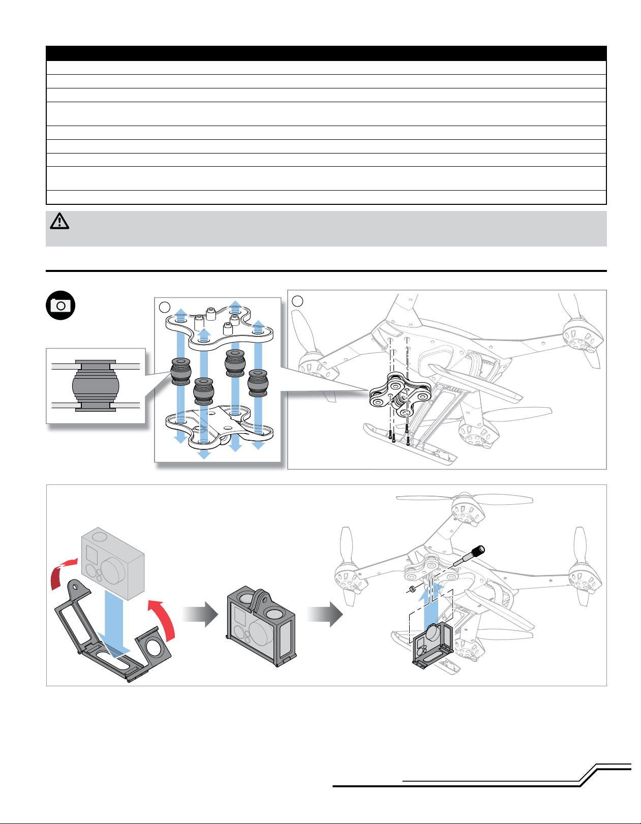
Mounting a Camera
IMPORTANT: Consult local laws and ordinances before installing and operating any type of photograph-capable or video recording device in this product.
1
Installing the Included Camera Frame to the Isolation Mount
* Camera not included
*
2
5
EN
Page 6

Transmitter Setup (BNF)
CAUTION: When using a Futaba transmitter with a Spektrum DSM module, you must reverse the throttle channel and rebind. Refer to your Spektrum module
manual for binding and failsafe instructions. Refer to your Futaba transmitter manual for instructions on reversing the throttle channel.
Transmitter Model
Type
DX4e (New)*
w/3-position
switch
DX5e (New)*
w/3-position
switch
DX6i Acro
DX7/7SE Acro
DX7S Acro
N/A N/A N/A N/A
N/A N/A N/A N/A
Reverse
Setup
THRO-N
ELEV-N
GEAR-R
AILE-N
RUDD-N
FLAP-N
FLAP-R (6)
Others-N
AUX1-R
Others-N
Throttle
Cut
Setup
ACT
N/A
Set To:
Trainer
Mode Setup Switch Positions Throttle Cut Return Home Dual Rate
Switch
Travel Adj: GEAR POS (0) GEAR: ↑100%;
GEAR/F MODE POS (1) GEAR: ↓40%
FLAPS: Norm ←↑100; LAND ↓100
MIX 1: ACT; GEAR → GEAR ACT
RATE D 0%; U + 100%
SW MIX TRIM INH
SUB TRIM THRO ↑ 15-20%
Travel Adj: GEAR (0)↑100%;
GEAR (1) ↓40%
MIX 1: FLAP → Gear OFF/ON
RATE → -50%
0%
SW: MIX OFFSET: 0
Switch Select:
Move Gear to F MODE (F MODE:GEAR)
Leave FLAPS as AUX1
Set All Others to INH
MIX 1: GER > GER
RATE: 0%
-100%
OFFSET: 0%; TRIM: INH; SW: Mix0
Position 0 = SMART Mode
Position 1 = Stability Mode
Position 2 = Agility Mode
Position 0 = SMART Mode
Position 1 = Stability Mode
Position 2 = Agility Mode
GEAR 0; Mix 0 = SMART Mode
GEAR 1; Mix 0 = Stability Mode
GEAR 1; Mix 1 = Agility Mode
GEAR (0);
Mix (0) = SMART Mode
GEAR (1);
Mix (0) = Stability Mode
GEAR (1);
Mix (1) = Agility Mode
F MODE (0) = SMART Mode
F MODE (1);
HOLD (1) = Agility Mode
Lower throttle
trim until motors
stop turning
Lower throttle
trim until motors
stop turning
Press throttle cut
Lower throttle
trim until motors
stop turning
Press
Trainer
Press and Hold
TRAINER/BIND
Release to EXIT
Press and Hold
TRAINER/BIND
Release to EXIT
FLAP Position 0
= OFF
FLAP Position 2 =
Return Home
FLAP Pos 0
= OFF
FLAP Pos 1
= Return Home
FLAP Pos 0 = OFF
FLAP Pos 2 =
Return Home
Rate
Rate
ELEV-AIL D/R 100% 70%
ELEV-AIL D/R 100% 70%
ELEV-AIL D/R 100% 70%F MODE (1) = Stability Mode
High
Rate
100%
fi xed
100%
fi xed
Low
Rate
70%
fi xed
70%
fi xed
DX8 Acro
DX9/DX18 Acro
AUX1-R
Others-N
AUX1-R
Others-N
Set To:
Trainer
Set To:
I (BIND)
Switch Select: F-Mode to Gear;
Flap to Aux 1
All Others to INH
Channel Assign: NEXT
1-4: N/A 5 Gear: B
6 AUX1: D 7 AUX2: I
8-10: INH
F MODE (0) = SMART Mode
Press Trainer/
Bind
F MODE (2) = Agility Mode
B (0) = SMART Mode
Press I (BIND)
B (2) = Agility Mode
FLAP Pos 0
= OFF
FLAP Pos 2
= Return Home
D (FLAP) Pos 0
= OFF
D (FLAP) Pos 2 =
Return Home
ELEV-AIL D/R 100% 70%F MODE (1) = Stability Mode
ELEV-AIL D/R 100% 70%B (1) = Stability Mode
* Old versions of the DX4e and DX5e (with 2-position channel 5 switches) are not recommended for the 350 QX. Only Smart Mode and Agility Mode will be
available with GPS On.
EN
6
Page 7

Transmitter Control Layout (RTF)
Dual Rate Switch
(Mode 1) not shown
Bind/Trainer Switch
(Mode 2)
Flight Mode Switch
(Mode 2)
Rudder/Yaw
(Modes 2 and 1)
Throttle/Altitude
(Mode 2)
Elevator/Pitch
(Mode 1)
Rudder Trim
Throttle Trim
(Mode 2)
Elevator Trim
(Mode 1)
Channel Reversing Switches
Dual Rate Switch
(Mode 2)
Bind/Trainer Switch
(Mode 1) not shown
Flight Mode Switch
(Mode 1) not shown
Aileron/Roll
(Modes 2 and 1)
Elevator/Pitch
(Mode 2)
Throttle/Altitude
(Mode 1)
Aileron Trim
Elevator Trim
(Mode 2)
Throttle Trim
(Mode 1)
Power Switch
Connecting the Flight Battery
3
1
Remove the battery cover Install the battery
4
3
2
1
2
7
EN
Page 8

Binding
• If you purchased the ready-to-fl y (RTF) model, the transmitter is bound to the model at the factory. If for any reason the model needs to be re-bound, follow the
directions for the Bind-N-Fly
To bind or re-bind your 350 QX to your chosen DSM2/DSMX transmitter, please follow the directions below along with the binding instructions
included with your transmitter:
®
®
(BNF) version below.
The Binding Process
1. With the transmitter and quadcopter powered off, connect the battery
to the 350 QX.
2. With the 350 QX on a level surface, turn on the power switch and allow
the quadcopter to initialize.
3. Wait until the blue LED on the quadcopter fl ashes rapidly, signaling the
quadcopter is initialized and ready to bind.
4. Ensure throttle is in the low position and throttle trim is at neutral.
5. Hold the control sticks in the desired bind position (see illustrations)
and press/pull the bind button/switch, then power on the transmitter.
6. Refer to the Flying LED Codes table to ensure the aircraft is bound
correctly.
IMPORTANT: Do not attempt to bind with more than one bind code.
Binding with more than one bind code will only allow the aircraft to
bind normally.
Unless binding with a bind code, the elevator and aileron inputs (including trim) must be neutral during binding. If you are attempting a normal
bind with any input other than neutral, the aircraft will emit a constant,
rapid beeping sound.
If your 350 QX emits a constant beeping sound after binding
(Smart or Agility Mode only):
1. Ensure all trims are neutral.
2. Slowly move the elevator stick back and forth (close to center) and
listen for the beeping to stop or hesitate. Take note of the direction
you are moving the stick when the change of tone happens.
3. If the tone never changes with elevator movement, slowly move the
aileron stick back and forth (close to center) and listen for the beeping to stop or hesitate. Take note of the direction you are moving the
stick when the change of tone happens.
4. Input trim in the direction that caused the change in tone until the
beeping stops.
In the event you cannot fi nd an input that stops the tones:
1. Apply 1 click of elevator trim in either direction and then slowly
move the aileron stick close to center.
2. Continue to add 1 click at a time of elevator trim, up to 5 trim steps
off center up or down, and move the aileron stick until you fi nd the
point that makes the tones stop.
3. Add aileron trim in the direction you moved the stick to make the
tones stop.
Entering Bind Mode
Bind switch
(Trainer switch)
TRAINER
Transmitter Bind Codes
TRAINER
TRAINER
TRAINER
Normal Bind
Mode 2 shown
Roll left
Bind with GPS enabled
Roll right
Bind with GPS disabled
EN
Yaw left
Bind in compass calibration mode
TRAINER
Yaw right
Bind in pressure calibration mode
8
Page 9

Flight Mode Switches
GPS Enabled Functions
Return Home
(Rapid Red fl ashing LED
on the 350 QX)
Smart Mode
(Solid Green LED on the 350 QX)
Stability Mode
(Solid Blue LED on the 350 QX)
Agility Mode
(Solid Red LED on the 350 QX)
Flight Modes Explained
TRAINER
Stick Relativity
Elevator input Aileron input
Forward
Back
Aircraft response
relative to the
pilot location
Stability and Agility Mode Control Inputs
Forward elevator
SAFE Circle
Flight Mode 0– Smart Mode (Default)
(Solid Green Indicator LED)
Right Left
path of the aircraft will always follow the control stick
input direction relative to the SAFE Circle, regardless of
the direction the nose of the aircraft is pointing.
Stick Relativity– While in Smart Mode, the
• SAFE Circle
enter the SAFE Circle.
• Position Hold– The aircraft will hold its position
when elevator and aileron inputs are at neutral.
• Self-Leveling– Brings the 350 QX to a level attitude
when the elevator and aileron inputs are at neutral.
• Altitude Command– Altitude is relative to throttle
stick position.
attitude when the elevator and aileron inputs are
at neutral.
• Position Hold– The 350 QX uses GPS to hold a
given location when this function is activated. If
GPS is enabled and has a solid lock, the aircraft will
hold its position when elevator or aileron inputs are
at neutral.
• Throttle provides proportional thrust– The throttle
responds directly to the throttle input, giving the
pilot direct control over hovering as well as ascent
and descent rates.
™
– In most scenarios, the quad will not
Flight Mode 1– Stability Mode
(Solid Blue Indicator LED)
• Self-Leveling– Brings the 350 QX to a level
Left aileron Right aileron
Back elevator
The Blade 350 QX fl ies very differently in the different fl ight modes. Beginners should
use Smart Mode to start and progress slowly into Stability Mode. When fl ying in
Smart Mode, the quadcopter follows stick input based on the set pilot location. When
fl ying in Stability Mode, the quadcopter follows stick inputs based on the orientation
of the aircraft. The transition from Smart Mode to Stability Mode can be a challenge
for new fl yers because the pilot will need to learn how to interpret the aircraft’s
orientation.
NOTICE: Do not attempt to fl y your 350 QX in Stability Mode or Agility Mode until you have familiarized yourself with the operation of the aircraft in Smart Mode
and read and understand the descriptions of the other fl ight modes.
This aircraft is extremely sensitive to control inputs in Agility Mode and has NO self
leveling. We recommend you fl y at low rate settings for the fi rst few fl ights until you
are familiar with its response. For pilots new to quadcopters and helicopters, familiarize yourself with the Blade 350 QX in Smart Mode and at low rate.
As you become more familiar with the quadcopter’s response, adjust the rates and
expo to suit your fl ying style (if using a computer radio).
Flight Mode 2– Agility Mode
(Solid Red Indicator LED)
• Aerobatic– Capable of fl ips and rolls
• Throttle provides proportional thrust– The throttle
responds directly to the throttle input, giving the
pilot direct control over hovering and ascent and
descent rates.
9
EN
Page 10

Audible Alerts and LED Codes
The motors will Beep under the following conditions:
• Any time the props stop spinning after they have
been initialized.
• After 30 seconds of no throttle input
(waiting armed on the ground).
Audible Alerts
Event Audible Alert
ESC power on one short beep
Successful initialization many continuous tones with increasing frequency
RC signal detected after start one long tone
Bind detected one long tone
Bind accepted (3 seconds after detected) one long tone
Thrust stick in correct position for motor start low, med, high (happy tone)
Cannot start motors because of low voltage high, med, low (sad tone)
Cannot start motors because vehicle is tilted high, med, low (sad tone)
Enter ESC ID assignment mode loud high, low — high, low
Initialization Audible Alerts
Event Audible Alert
Gyro, accelerometer sensor error High, low, 1 short tone
Compass initialization error High, low, 2 short tones
Pressure sensor initialization error High, low, 3 short tones
GPS initialization error High, low, 4 short tones
ESCs not detected High, low, 6 short tones
Settings saved (i.e. when changed GPS on/off, etc) Rapid low, med, high — low, med, high
Trim warning (when in Smart or Agility Mode) Continuous very short, rapid tone
Low-battery warning Medium frequency, loud tone (every 3 seconds)
Emergency state warning
(also after ESC ID assignment)
Once per second loud medium tone
Startup LED Codes
Fully charged battery Green (~2 second duration)
Partial battery charge
Fully discharged battery Red (~2 second duration)
(cycle power to reinitialize)
Return to home mode activated Rapid red fl ashing
The quadcopter is in Bind mode Rapid blue fl ashing
Sequence
Initialization failed Pulsing red
IMU initialization Red, green and blue fl ash once
Color indicates level of battery charge
(~2 second duration)
Emergency mode
1 second 1 second
1 second
White fl ashing
EN
10
Page 11

Flying LED Codes
Smart Mode, with GPS lock
Sequence
Solid green
Smart Mode, no GPS lock
Stability Mode, with pressure
Stability Mode, with GPS lock
Stability Mode, no GPS lock
Stability Mode, GPS disabled
Agility Mode, with GPS lock
Agility Mode, no GPS lock 3 red fl ashes, pause
Agility Mode, GPS disabled Slow red fl ash
Flight mode set to Smart Mode
Flight mode set to Stability Mode Shows fl ight mode position on motor startup
Flight mode set to Agility Mode
Flight battery voltage below 10.9V Red, green and blue fl ash (~3 second cycle)
Flight battery voltage below 10.6V Red, green and blue fl ash (~1 second cycle)
1 second
1 second
1 second
3 green fl ashes, pause
Slow green fl ash
Solid blue
3 blue fl ashes, pause
Slow blue fl ash
Solid red
CAUTION: If you see the LED signal for low battery, immediately land your aircraft and recharge the battery.
CAUTION: Do not attempt to use Return Home with a low battery.
Calibration LED Codes
Sequence
Gyro temperature calibration*
No calibration
Compass calibration entered
Compass calibration started
Pressure sensor temperature calibration
Pressure and gyro calibration*
Accelerometer offset calibration entered
Accelerometer offset calibration started
(in fl ight only)
(in fl ight only)
Calibration failed
1 second
* These items are performed by the manufacturer.
1 second
Rapid green and blue fl ashing
Green pulsing
Slow red and green fl ashing
Rapid red and green fl ashing
Rapid red and blue fl ashing
Rapid red, green and blue fl ashing
Slow red, green and blue fl ashing
Rapid red, green and blue fl ashing
Solid white
1 second
11
EN
Page 12

GPS Functionality of the 350 QX
To acquire a reliable GPS signal, it is important the 350 QX has a clear view of
the sky. Obstructions that can affect the aircraft’s ability to acquire an acceptable
signal include:
• Flying close to or around tall/big buildings
• Flying under dense vegetation
• Flying indoors or under a structure
If you lose or cannot acquire a GPS lock and home position, the aircraft will not
have Stick Relativity, SAFE Circle, Position Hold or Return Home functions available.
It is not possible to use Smart Mode without having GPS enabled. If the 350 QX
is initialized without GPS enabled, it will default to Stability Mode. The aircraft
will still be capable of altitude hold.
If you do not have a GPS signal, try maneuvering the 350 QX by steering with
forward elevator and rudder only.
CAUTION: Do not attempt to fl y the 350 QX with GPS enabled while
indoors or in a location where the GPS signal is known to be poor, as
loss of signal could result in a crash.
GPS Functions
(see the binding section for turning GPS functions ON and OFF )
With GPS ON
• If the 350 QX took off with GPS lock and a home position set, when Return
Home mode is activated the quadcopter will fl y back to the start position
(maintaining altitude along the way), then reduce altitude to land.
• If the 350 QX should lose GPS when Return Home mode is activated, it will
land quickly using the barometric pressure sensor to maintain the descent
rate.
• If the 350 QX took off without GPS lock, but acquires a GPS signal in fl ight, it
will land slowly using GPS to hold its position and barometric pressure sensor to maintain the descent rate when Return Home mode is activated.
• If the 350 QX loses GPS during landing in Return Home mode, it will increase the rate of descent and land quickly to avoid drift.
• If the 350 QX deviates too far from its intended GPS path when in Return
Home mode, it will descend using the barometric pressure sensor to maintain the descent rate. This could happen if the fl ight control system loses its
orientation because of aggressive fl ight in 3 axis mode.
• Once the 350 QX has landed in Return Home mode it will disarm the motors
With GPS OFF
• If Return Home mode is activated, the 350 QX will level off and land quickly
using the barometric pressure sensor to maintain the descent rate.
• Once the 350 QX has landed in Return Home mode it will disarm the motors.
GPS Failure
Upon GPS failure, the 350 QX will respond according to the following conditions:
Smart Mode: (rapid Green fl ashing LED)
If the 350 QX is in this mode and the GPS fails, the quad will default to
Stability Mode. The aircraft will still use the pressure sensor to maintain
altitude and control rate of descent. If GPS is re-acquired, after 5-10
seconds of reliable GPS signal the Smart Mode functions are returned to
normal
Stability Mode: (long Blue, two short Green fl ashing LED)
If the 350 QX is in this mode and the GPS fails, it will not switch to Smart
Mode and will not enter GPS hold, but will otherwise function normally. If
GPS is reacquired, after 5-10 seconds of reliable GPS signal the Stability
Mode functions are returned to normal
Agility Mode: (long Red, two short Green fl ashing LED)
If the 350 QX is in this mode and the GPS fails, it will not affect fl ight performance, but it will not be able to switch into Smart Mode. It will still be able
to switch into Stability Mode with the limitations described above.
Loss of Transmitter Signal
If the transmitter signal is lost for any reason, the 350 QX will respond according
to the following conditions:
• If the motors are not turning, the 350 QX will disarm.
• If the motors are turning but the 350 QX is not fl ying, it will turn off the motors and disarm.
• If the 350 QX is fl ying and has a good GPS lock with a home position set,
it will activate the Return Home function upon the loss of the transmitter
signal.
• If the compass is not connected or faulty, or if there is no GPS lock, the 350
QX will descend slowly upon the loss of the transmitter signal.
• If the pressure sensor is not working, the 350 QX will reduce power to initiate a controlled descent upon the loss of the transmitter signal.
Flight Guidelines and Warnings
• Always keep aircraft in sight and under control.
• Always keep people and pets at least 35 feet (10 meters) away when the
battery is connected.
• Keep children out of the vicinity of this product at all times.
• Always use fully charged batteries.
• Always keep transmitter powered on while aircraft is powered.
• Always remove batteries before disassembly.
• Always keep moving parts clean.
• Always keep parts dry.
EN
• Always let parts cool after use before touching.
• Always remove batteries after use.
• Always have a fi rst aid kit with you.
• Always have an appropriate fi re extinguisher with you.
• Never operate aircraft with damaged wiring.
• Never touch moving parts.
The Blade 350 QX has many more features than other Blade quadcopters.
Please take the time to read this manual and understand the functions this
aircraft contains before fl ying.
12
Page 13

Preparing the 350 QX For Flight
Smart Mode Flying
350 QX home location
SAFE Circle
Pilot location
16 feet (5 meters)
1. Power on the transmitter with the fl ight mode set to
Smart Mode, the throttle stick down and the throttle
trim at neutral.
2. Install a charged battery, plug it in and close the
hatch.
3. With the quad on a level surface, turn on the power
switch and allow the 350 QX to initialize.
If the GPS is enabled, wait for the GPS signal to be
acquired, which is indicated by a solid green LED.
It may take from 30–90 seconds to acquire a GPS
signal.
IMPORTANT: While in Smart Mode the motors will
not start if a GPS signal has not been acquired.
4. Move the aircraft to the desired home location and
orient the aircraft pointed away from the pilot.
5. Step back approximately 16 feet (5 meters) from the
home location.
6. When you are prepared to fl y, quickly move the rudder stick all the way left and then all the way right.
The props will begin to spin. The home position for
GPS functions is set and your aircraft is ready to fl y.
IMPORTANT: The motors will not start if the transmitter is set to low rate. The dual rate switch must be set
to high rate.
Lower the throttle stick and the throttle trim to power
off the props after fl ight.
CAUTION: When the home location is set (step 6), the 350 QX must be approximately 16 feet (5 meters) from where the pilot will stand during fl ight, pointing
away from the pilot. If the aircraft is pointed in any other direction, the SAFE Circle feature will not function as expected and may result in personal injury or
damage to property. Once the aircraft’s motors are started, do not change your position.
Flying the 350 QX
Smart Mode Altitude Control
Mode 2 shown
Full throttle
Half throttle
Low throttle
Maximum altitude
(approximately 45 meters)
Intermediate altitude
Takeoff
Increase the throttle slightly above low stick (10–15%).
The 350 QX altitude in Smart Mode corresponds to the
throttle position. Low throttle is on the ground, slightly
raising the throttle will produce a low hover, and the
higher the throttle position, the higher the 350 QX will
ascend until it reaches its maximum altitude (approximately 45 meters).
Explore the fl ight envelope of the 350 QX in Smart
Mode without fear of losing orientation. See the
diagrams in the Flight Modes Explained section for
more details on the aircraft’s function in Smart Mode.
In Smart Mode, the direction the aircraft is pointing
does not affect the control, and the aircraft’s response
relative to you (the pilot location) does not change with
orientation. Stability Mode and Agility Mode operate
more like a conventional RC helicopter or multicopter.
IMPORTANT: Aggressive fl ight in Agility Mode will
signifi cantly reduce fl ight time.
On the ground
13
EN
Page 14

Landing
To land the 350 QX there are two options:
• Guide the aircraft to where you wish to land and
reduce the throttle. Reduce the throttle trim after
landing to disarm the motors.
• Activate the Return Home function to return the
350 QX to the assigned home location and land
automatically.
CAUTION: Do not activate the Return Home
function if the 350 QX is showing the low
battery indication. Manually land the aircraft
immediately.
Return Home
• When this feature is activated, the 350 QX will
fl y back to its assigned home location and
land. After landing, the motors may take up to
5 seconds to disarm. If the motors take more
than 20+ seconds to disarm, perform the
Pressure Sensor Calibration.
• To restart the props after landing in Return Home,
fully lower the throttle and ensure the throttle trim is
neutral, then quickly move the rudder stick fully left
and then fully right.
CAUTION: The 350 QX will not recognize the
SAFE Circle feature when Return Home is
used. Activating Return Home may cause the 350 QX
to fl y directly over the pilot if the aircraft was fl own to
a position behind where the pilot was standing when
the home position was established.
After Your Flight
1. Turn off the power switch on the 350 QX.
2. Turn off the power to your transmitter.
3. Unplug and remove the battery from the 350 QX.
CAUTION: Always disconnect the Li-Po bat-
tery from the aircraft when not fl ying to avoid
over-discharging the battery. Batteries discharged to a
voltage below the lowest approved voltage may become
damaged, resulting in loss of performance and potential
fi re when batteries are charged.
Location alert
The motors will Beep under the following conditions:
• At any time the props stop spinning after they have
been initialized.
• After 30 seconds of no throttle input (waiting armed
on the ground).
This will alert the pilot to the location of the aircraft if it
lands in a location with low visibility.
Beeping will continue until the battery can no longer
supply enough power to the motors.
If the quadcopter crash lands and one or more motors
are stopped by an impact, the quadcopter enters
emergency mode. The LED will fl ash white and the
motors will beep loudly.
Activating Return Home
Press and hold.
Releasing the switch
will stop the Return Home
program.
TRAINER
EN
14
Page 15

Airframe Maintenance
Body Screw
Locations
Internal Components
Motors
ESCs
GPS receiver
GPS antenna
Battery tray assembly
Flight control board
Replacing the body
Disassembly of the old airframe
1. Ensure the battery is disconnected from the
quadcopter.
2. Remove the 2 machine screws from each propeller
and remove the propellers.
3. Remove the 32 1.5mm hex screws from the bottom
of the frame to separate the upper and lower body
pieces.
4. Unplug the compass sensor from the fl ight control
board. Remove the landing gear with compass sensor and place it in a safe area away from magnets.
NOTICE: Do not allow the compass sensor to
get near a magnet. Any magnet, including those in
the 350 QX motors, can damage the compass and
cause it to work incorrectly. If the 350 QX is fl own
with a faulty compass, all GPS functions will be
compromised.
5. Unplug the GPS receiver from the fl ight control
board and remove the battery tray assembly.
6. If you are replacing the GPS components, remove
the foil from the GPS receiver and unplug the GPS
antenna from the GPS receiver.
7. Remove the fl ight control board from the airframe.
8. Remove the motors and ESCs from the airframe.
Before installing the components into the new airframe,
inspect all the components for any obvious damage or
burnt smells. Check the motors for smooth bearings
and inspect all the propellers for chips, burrs or cracks.
Replace any parts in question.
Propeller Direction of Rotation Indicators
Installing components in the new airframe
1. Install the motors and ESCs, making sure to match
the wire colors on the connectors.
2. Install the fl ight control board.
3. Install the tray assembly.
4. Install the GPS receiver and GPS antenna and plug
the cables into their corresponding sockets.
5. Assign the motors and ESCs according to the
ESC and Motor Assignment Procedure.
6. Install the landing gear and connect the compass
to the fl ight control board. If you replaced the
compass or believe that it may have been impaired
by a magnetic fi eld, you will need to perform the
compass calibration procedure.
7. Mount the top of the airframe.
8. Install the propellers, paying attention to the
direction of rotation as indicated by the arrows
molded in the frame and on the propellers for each
motor.
Rotation
direction
Motor number
15
EN
Page 16

Compass Calibration
The Flight Controller on the 350 QX has automatic magnetic declination calibration, so you will not have to worry about looking up the magnetic declination at
your location and changing settings on your 350 QX to get accurate compass
measurements. It is possible, however, that your compass may need to be calibrated if it is exposed to strong magnetic fi elds.
Compass calibration procedure:
1. Go to an open space outdoors away from metal. Take a conventional compass with you to ensure you know the direction of north.
2. Ensure your transmitter is off and then connect a fl ight battery to the 350
QX. Power the aircraft on. Wait fi ve seconds and then the blue LED will
begin fl ashing rapidly, signaling the aircraft is initialized and ready to bind.
3. Once the blue light begins fl ashing, bind with yaw stick left. The 350 QX LED
will slowly fl ash between red and green for 5 seconds.
4. Put the 350 QX fl at in your hands and face north. After 5 seconds of slow
fl ashing the quad will start fl ashing rapidly. The quad is now collecting data
to be used for the calibration.
5. Slowly rotate the quad 360 degrees about the east-west axis (“fl ip” the
aircraft either forward or backward) until it is fl at in your hands again.
Compass Calibration Steps
North
6. Continue facing north and yaw the quad 45 degrees left so the quad is now
facing north-west.
7. Slowly rotate the quad 360 degrees about the east-west axis, (“fl ip” the
aircraft diagonally either direction) until it is fl at in your hands again.
8. Continue facing north and yaw the quad 45 degrees left so the quad is now
facing west.
9. Slowly rotate the quad 360 degrees about the east-west axis (“fl ip” the
quad sideways either direction) until it is fl at in your hands again.
10. Continue facing north and yaw the quad 45 degrees left so the quad is now
facing south-west.
11. Slowly rotate the quad 360 degrees about the east-west axis (“fl ip” the
aircraft diagonally either direction) until it is fl at in your hands again.
You have 30 seconds to complete the procedure. The 350 QX should still be
blinking rapidly when you fi nish. Hold the aircraft still until it stops blinking rapidly. If successful, the 350 QX will beep a positive confi rmation and then restart
itself. If unsuccessful, the 350 QX displays the failed calibration code, a solid
white LED. If the 350 QX displays this error code, power off the aircraft and then
begin the calibration procedure again.
Step 5 Step 7 Step 9 Step 11
Pressure Sensor Calibration
The pressure sensor is calibrated at the factory on the 350 QX. Recalibration
should only be necessary if you replace the sensor.
1. Place the 350 QX in a cold area. Allow it to remain in the cold for 30 minutes
or more.
2. Bring the 350 QX out of the cold and into a warm area. The greater the difference in temperature between the cold and warm areas, the more accurate the
calibration will be.
3. Ensure your transmitter is off and then connect a fl ight battery to the 350 QX
and power the aircraft on. Wait fi ve seconds and then the blue LED will begin
fl ashing rapidly, signaling the aircraft is initialized and ready to bind.
Accelerometer Calibration
To calibrate the accelerometer, the quadcopter needs to fl y for 20 seconds while
being level. This allows the accelerometer readings to be averaged and stored in
memory.
Use the following procedure to calibrate the accelerometer:
1. Power on the quadcopter with the transmitter off to enter bind mode.
2. Turn on the transmitter while holding the elevator stick back and pressing
the bind switch.
3. Set the fl ight mode switch to Stability Mode or Smart Mode. The quadcopter
will fl y in Stability Mode no matter which position is selected.
4. Start the motors. Fly the quadcopter off the ground. The quadcopter LED will
fl ash slowly (red, green, blue).
5. Use trims to adjust roll/pitch so the quadcopter does not drift left/right and
forward/back.
6. Activate the accelerometer calibration mode by changing the fl ight mode
switch into Agility Mode. The vehicle will still fl y in Stability Mode. The LED
will start fl ashing quickly (red, green, blue).
4. Once the blue light begins fl ashing, bind with yaw stick right. The 350 QX will
blink red and blue rapidly. Leave the aircraft and transmitter powered on and
allow the aircraft to warm up for 10 minutes. Do not move the aircraft during
this time.
5. After 10 minutes the motors on the aircraft will beep to indicate the calibration
is complete. Power off the aircraft and then your transmitter.
If the 350 QX displays the failed calibration code, power off the aircraft and then
begin the pressure calibration procedure again.
7. Fly steadily for 10–30 seconds. The LED will fl ash slowly when data
collection is done.
8. Land the quadcopter and stop the propellers by lowering the throttle and
throttle trim.
IMPORTANT: The calibrated values are not yet permanently stored. Do not turn
off the quadcopter.
9. Center the trims on the transmitter. Start the motors and verify the
quadcopter fl ies without drifting.
10. Land the quadcopter and stop the motors by lowering the throttle and
throttle trim.
11. Save the calibration by moving the rudder stick quickly left, right, left, right.
Values are saved when you hear a rapid triple tone twice.
12. Turn off the quadcopter.
13. Confi rm the calibration by powering up the quadcopter and performing a test
fl ight. If the calibration is not correct, start the calibration procedure again.
EN
16
Page 17

ESC and Motor Assignment Procedure
Motor Numbers
Motor number 1
Motor number 4
Troubleshooting
Problem Possible Cause Solution
350 QX will not initialize
GPS will not lock
GPS has reduced resolution
GPS functions not operating
properly
Motors will not start in
Smart Mode
Motors will not start in
Stability/Agility Mode
Blades take a long period of
time to shut off after completing
return to home
The quadcopter has trouble
fi nding the home position and
the props will not shut off after
returning home
1. Begin with the transmitter off and connect a fl ight
battery to the 350 QX.
Motor number 2
Motor number 3
The quadcopter was moved during initialization
Throttle trim is not in the correct position The trim may need to be adjusted a click above or below center
Heavy overcast Wait for lighter cloud cover and re-lock or disable GPS
Solar fl ares Wait for disturbance to subside or disable GPS
Aircraft is indoors Disable GPS
Objects blocking clear access to the sky
(under a metal cover, inside a car, tall buildings, etc...)
Video transmitter nearby Re-position or remove video transmitter
Raised threat level by the U.S. government Wait for threat level to be reduced or disable GPS
The GPS antenna coaxial cable is nicked, cut,
or otherwise damaged
The compass has been exposed to a magnet
The GPS antenna coaxial cable is nicked, cut, or otherwise damaged
The aircraft is behaving erratically Rebind the aircraft with the GPS function off
Aggressive fl ight Fly level for a few seconds before fl ipping into other modes
Rate mode switch set to low Set transmitter dual rate switch to hi
GPS signal is not aquired Ensure a GPS signal is aquired
Rudder trim not centered Center the rudder trim
Rate mode switch set to low Set transmitter dual rate switch to hi
Rudder trim not centered Center the rudder trim
Pressure calibration is needed Refer to the Pressure Sensor Calibration section of this manual
Accelerometer calibration is needed Refer to the Accelerometer Calibration section of this manual
Re-arm the aircraft, being cautious to avoid any movement during
initialization
Move aircraft to a clear area
Replace the GPS antenna
Move the aircraft away from the magnetic source. In worst case scenario, the compass may need to be replaced
Replace the GPS antenna
2. Power on the quadcopter on a level surface and wait for
the rapid blue fl ashing LED to indicate the aircraft has
entered bind mode.
3. With the throttle stick in the full throttle position, press/
pull the bind button/switch and power on your transmitter.
The quadcopter will acknowledge the assignment mode
with a loud high, then low tone. If your transmitter is
equipped with a high throttle warning at startup, it is necessary to disable this alarm prior to completing this step.
After the replacement procedure is complete, re-activate
the high throttle warning in your transmitter.
4. The motor number and prop direction are molded in the
top of the body. The motors will give an audible “beep” to
indicate which motor to calibrate. When the motors beep
1 time, spin motor 1 by hand. The motor will respond with
the same number of tones upon successful assignment.
5. When the motors beep 2 times, spin motor 2 by hand.
6. When the motors beep 3 times, spin motor 3 by hand.
7. When the motors beep 4 times, spin motor 4 by hand.
When the assignment is successful, the quadcopter enters
emergency mode. Restart the quadcopter.
17
EN
Page 18

Limited Warranty
What this Warranty Covers
Horizon Hobby, Inc., (Horizon) warrants to the original purchaser that the product purchased (the
“Product”) will be free from defects in materials and workmanship at the date of purchase.
What is Not Covered
This warranty is not transferable and does not cover (i) cosmetic damage, (ii) damage due to
acts of God, accident, misuse, abuse, negligence, commercial use, or due to improper use,
installation, operation or maintenance, (iii) modi cation of or to any part of the Product, (iv)
attempted service by anyone other than a Horizon Hobby authorized service center, (v) Product
not purchased from an authorized Horizon dealer, or (vi) Product not compliant with applicable
technical regulations.
OTHER THAN THE EXPRESS WARRANTY ABOVE, HORIZON MAKES NO OTHER WARRANTY
OR REPRESENTATION, AND HEREBY DISCLAIMS ANY AND ALL IMPLIED WARRANTIES,
INCLUDING, WITHOUT LIMITATION, THE IMPLIED WARRANTIES OF NON-INFRINGEMENT,
MERCHANTABILITY AND FITNESS FOR A PARTICULAR PURPOSE. THE PURCHASER
ACKNOWLEDGES THAT THEY ALONE HAVE DETERMINED THAT THE PRODUCT WILL SUITABLY
MEET THE REQUIREMENTS OF THE PURCHASER’S INTENDED USE.
Purchaser’s Remedy
Horizon’s sole obligation and purchaser’s sole and exclusive remedy shall be that Horizon will,
at its option, either (i) service, or (ii) replace, any Product determined by Horizon to be defective.
Horizon reserves the right to inspect any and all Product(s) involved in a warranty claim. Service
or replacement decisions are at the sole discretion of Horizon. Proof of purchase is required for
all warranty claims. SERVICE OR REPLACEMENT AS PROVIDED UNDER THIS WARRANTY IS
THE PURCHASER’S SOLE AND EXCLUSIVE REMEDY.
Limitation of Liability
HORIZON SHALL NOT BE LIABLE FOR SPECIAL, INDIRECT, INCIDENTAL OR CONSEQUENTIAL
DAMAGES, LOSS OF PROFITS OR PRODUCTION OR COMMERCIAL LOSS IN ANY WAY,
REGARDLESS OF WHETHER SUCH CLAIM IS BASED IN CONTRACT, WARRANTY, TORT,
NEGLIGENCE, STRICT LIABILITY OR ANY OTHER THEORY OF LIABILITY, EVEN IF HORIZON HAS
BEEN ADVISED OF THE POSSIBILITY OF SUCH DAMAGES. Further, in no event shall the liability
of Horizon exceed the individual price of the Product on which liability is asserted. As Horizon
has no control over use, setup, nal assembly, modi cation or misuse, no liability shall be
assumed nor accepted for any resulting damage or injury. By the act of use, setup or assembly,
the user accepts all resulting liability. If you as the purchaser or user are not prepared to accept
the liability associated with the use of the Product, purchaser is advised to return the Product
immediately in new and unused condition to the place of purchase.
Law
These terms are governed by Illinois law (without regard to con ict of law principals). This
warranty gives you speci c legal rights, and you may also have other rights which vary from
state to state. Horizon reserves the right to change or modify this warranty at any time without
notice.
WARRANTY SERVICES
Questions, Assistance, and Services
Your local hobby store and/or place of purchase cannot provide warranty support or service.
Once assembly, setup or use of the Product has been started, you must contact your local
distributor or Horizon directly. This will enable Horizon to better answer your questions and
service you in the event that you may need any assistance. For questions or assistance, please
visit our website at www.horizonhobby.com, submit a Product Support Inquiry, or call the toll
free telephone number referenced in the Warranty and Service Contact Information section to
speak with a Product Support representative.
Inspection or Services
If this Product needs to be inspected or serviced and is compliant in the country you live and
use the Product in, please use the Horizon Online Service Request submission process found
on our website or call Horizon to obtain a Return Merchandise Authorization (RMA) number.
Pack the Product securely using a shipping carton. Please note that original boxes may be
included, but are not designed to withstand the rigors of shipping without additional protection.
Ship via a carrier that provides tracking and insurance for lost or damaged parcels, as Horizon is
not responsible for merchandise until it arrives and is accepted at our facility. An Online Service
Request is available at http://www.horizonhobby.com/content/_service-center_render-servicecenter. If you do not have internet access, please contact Horizon Product Support to obtain
a RMA number along with instructions for submitting your product for service. When calling
Horizon, you will be asked to provide your complete name, street address, email address and
phone number where you can be reached during business hours. When sending product into
Horizon, please include your RMA number, a list of the included items, and a brief summary of
the problem. A copy of your original sales receipt must be included for warranty consideration.
Be sure your name, address, and RMA number are clearly written on the outside of the shipping
carton.
NOTICE: Do not ship Li-Po batteries to Horizon. If you have any issue with a Li-Po battery,
please contact the appropriate Horizon Product Support of ce.
Warranty Requirements
For Warranty consideration, you must include your original sales receipt verifying
the proof-of-purchase date. Provided warranty conditions have been met, your Product
will be serviced or replaced free of charge. Service or replacement decisions are at the sole
discretion of Horizon.
Non-Warranty Service
Should your service not be covered by warranty, service will be completed and
payment will be required without notifi cation or estimate of the expense unless the
expense exceeds 50% of the retail purchase cost. By submitting the item for service
you are agreeing to payment of the service without noti cation. Service estimates are available
upon request. You must include this request with your item submitted for service. Non-warranty
service estimates will be billed a minimum of ½ hour of labor. In addition you will be billed for
return freight. Horizon accepts money orders and cashier’s checks, as well as Visa, MasterCard,
American Express, and Discover cards. By submitting any item to Horizon for service, you are
agreeing to Horizon’s Terms and Conditions found on our website http://www.horizonhobby.
com/content/_service-center_render-service-center.
ATTENTION: Horizon service is limited to Product compliant in the country of use
and ownership. If received, a non-compliant Product will not be serviced. Further,
the sender will be responsible for arranging return shipment of the un-serviced
Product, through a carrier of the sender’s choice and at the sender’s expense.
Horizon will hold non-compliant Product for a period of 60 days from notifi cation,
after which it will be discarded.
Warranty and Service Contact Information
Country of Purchase Horizon Hobby Contact Information Address
United States of America
United Kingdom
Germany
France
China
EN
Horizon Service Center
(Repairs and Repair Requests)
Horizon Product Support
(Product Technical Assistance)
Sales
Service/Parts/Sales:
Horizon Hobby Limited
Horizon Technischer Service service@horizonhobby.de
Sales: Horizon Hobby GmbH +49 (0) 4121 2655 100
Service/Parts/Sales:
Horizon Hobby SAS
Service/Parts/Sales:
Horizon Hobby – China
servicecenter.horizonhobby.com/RequestForm/
www.quickbase.com/db/
bghj7ey8c?a=GenNewRecord
888-959-2304
sales@horizonhobby.com
888-959-2304
sales@horizonhobby.co.uk
+44 (0) 1279 641 097
infofrance@horizonhobby.com
+33 (0) 1 60 18 34 90
info@horizonhobby.com.cn
+86 (021) 5180 9868
18
4105 Fieldstone Rd
Champaign, Illinois, 61822 USA
Units 1–4 , Ployters Rd, Staple Tye
Harlow, Essex, CM18 7NS, United Kingdom
Christian-Junge-Straße 1
25337 Elmshorn, Germany
11 Rue Georges Charpak
77127 Lieusaint, France
Room 506, No. 97 Changshou Rd.
Shanghai, China 200060
Page 19

FCC Information
This device complies with part 15 of the FCC rules. Operation is subject to the following two conditions:
(1) This device may not cause harmful interference, and (2) this device must accept any interference
received, including interference that may cause undesired operation.
CAUTION: Changes or modifi cations not expressly approved by the party responsible for
compliance could void the user’s authority to operate the equipment.
This product contains a radio transmitter with wireless technology which has been tested and found to
be compliant with the applicable regulations governing a radio transmitter in the 2.400GHz to 2.4835GHz
frequency range.
Antenna Separation Distance
When operating your Spektrum transmitter, please be sure to maintain a separation distance of at least
5 cm between your body (excluding fi ngers, hands, wrists, ankles and feet) and the antenna to meet RF
exposure safety requirements as determined by FCC regulations.
The following illustrations show the approximate 5 cm RF exposure area and typical hand placement
when operating your Spektrum transmitter.
IC Information
This device complies with Industry Canada license-exempt RSS standard(s).
Operation is subject to the following two conditions:
(1) this device may not cause interference, and (2) this device must accept any
interference, including interference that may cause undesired operation of the
device.
Compliance Information for the European Union
AT BE BG CZ CY DE DK
EE ES FI FR GR HR HU
IE IT LT LU LV MT NL
PL PT RO SE SI SK UK
IS LI NO CH
Declaration of Conformity
(in accordance with ISO/IEC 17050-1)
No. HH2013080502
Product(s): BLH 350 QX RTF
Item Number(s): BLH7800, BLH7800M1
Equipment class: 2
The object of declaration described above is in conformity with the requirements
of the specifi cations listed below, following the provisions of the European
R&TTE directive 1999/5/EC, EMC Directive 2004/108/EC and LVD Directive
2006/95/EC:
EN 300-328 V1.7.1: 2006
EN 301 489-1 V1.9.2: 2012
EN 301 489-17 V2.1.1: 2009
EN60950-1:2006+A11:2009+A1:2010+A12: 2011
EN61000-3-2:2006+A1:2009+A2:2009
EN61000-3-3:2008
EN55022:2010 + AC:2011
EN55024:2010
Signed for and on behalf of:
Horizon Hobby, Inc.
Champaign, IL USA
Aug 05, 2013
Chief Financial Offi cer
Robert Peak
Horizon Hobby, Inc.
Declaration of Conformity
(in accordance with ISO/IEC 17050-1)
No. HH2013080503
Product(s): BLH 350 QX BNF
Item Number(s): BLH7880
Equipment class: 1
The object of declaration described above is in conformity with the requirements
of the specifi cations listed below, following the provisions of the European
R&TTE directive 1999/5/EC, EMC Directive 2004/108/EC and LVD Directive
2006/95/EC:
EN 301 489-1 V1.9.2: 2012
EN 301 489-17 V2.1.1: 2009
EN61000-3-2:2006+A1:2009+A2:2009
EN61000-3-3:2008
EN60950-1:2006+A11:2009+A1:2010+A12: 2011
EN55022:2010 + AC:2011
EN55024:2010
Signed for and on behalf of:
Horizon Hobby, Inc.
Champaign, IL USA
Aug 05, 2013
Chief Financial Offi cer
Robert Peak
Horizon Hobby, Inc.
Instructions for disposal of WEEE by users in the European Union
This product must not be disposed of with other waste. Instead, it is the user’s responsibility to dispose of their waste equipment by handing it over to
a designated collections point for the recycling of waste electrical and electronic equipment. The separate collection and recycling of your waste equipment at the time of disposal will help to conserve natural resources and ensure that it is recycled in a manner that protects human health and the environment. For more information about where you can drop off your waste equipment for recycling, please contact your local city offi ce, your household
waste disposal service or where you purchased the product.
19
EN
Page 20

©2013 Horizon Hobby, Inc.
Blade, SAFE, SAFE Circle, the SAFE logo, Bind-N-Fly, the BNF logo, E-fl ite, Celectra, DSM, DSM2, DSMX,
and the Horizon Hobby logo are trademarks or registered trademarks of Horizon Hobby, Inc.
The Spektrum trademark is used with permission of Bachmann Industries, Inc.
US 7,391,320. Other patents pending.
Created 9/13 42408
 Loading...