

Blade Blade 450 X RTF, BLH1900, BLH1900M1 User guide

®
®
Instruction Manual
Bedienungsanleitung
Manuel d’utilisation
Manuale di Istruzioni

NOTICE
All instructions, warranties and other collateral documents are subject to change at the sole discretion of Horizon Hobby, LLC. For up-to-date product literature, visit
horizonhobby.com and click on the support tab for this product.
Meaning of Special Language
The following terms are used throughout the product literature to indicate various levels of potential harm when operating this product:
NOTICE: Procedures, which if not properly followed, create a possibility of physical property damage AND a little or no possibility of injury.
CAUTION: Procedures, which if not properly followed, create the probability of physical property damage AND a possibility of serious injury.
WARNING: Procedures, which if not properly followed, create the probability of property damage, collateral damage, and serious injury OR create a high probability of
superfi cial injury.
WARNING: Read the ENTIRE instruction manual to become familiar with the features of the product before operating. Failure to operate the product correctly
can result in damage to the product, personal property and cause serious injury.
This is a sophisticated hobby product. It must be operated with caution and common sense and requires some basic mechanical ability. Failure to operate this Product
in a safe and responsible manner could result in injury or damage to the product or other property. This product is not intended for use by children without direct
adult supervision. Do not use with incompatible components or alter this product in any way outside of the instructions provided by Horizon Hobby, LLC. This manual
contains instructions for safety, operation and maintenance. It is essential to read and follow all the instructions and warnings in the manual, prior to assembly, setup
or use, in order to operate correctly and avoid damage or serious injury.
Age Recommendation: Not for children under 14 years. This is not a toy.
Safety Precautions and Warnings
• Always keep a safe distance in all directions around your model to avoid collisions or injury. This model is controlled by a radio signal subject to interference
from many sources outside your control. Interference can cause momentary loss
of control.
• Always operate your model in open spaces away from full-size vehicles, traffi c
and people.
• Always carefully follow the directions and warnings for this and any optional
support equipment (chargers, rechargeable battery packs, etc.).
• Always keep all chemicals, small parts and anything electrical out of the reach
of children.
• Always avoid water exposure to all equipment not specifi cally designed and
protected for this purpose. Moisture causes damage to electronics.
• Never place any portion of the model in your mouth as it could cause serious
injury or even death.
WARNING AGAINST COUNTERFEIT PRODUCTS: If you ever need to replace a Spektrum component found in a Horizon Hobby product, always purchase from
Horizon Hobby, LLC or a Horizon Hobby authorized dealer to ensure authentic high-quality Spektrum product. Horizon Hobby, LLC disclaims all support and
warranty with regards, but not limited to, compatibility and performance of counterfeit products or products claiming compatibility with DSM or Spektrum.
• Never operate your model with low transmitter batteries.
• Always keep aircraft in sight and under control.
• Always move the throttle fully down at rotor strike.
• Always use fully charged batteries.
• Always keep transmitter powered on while aircraft is powered.
• Always remove batteries before disassembly.
• Always keep moving parts clean.
• Always keep parts dry.
• Always let parts cool after use before touching.
• Always remove batteries after use.
• Never operate aircraft with damaged wiring.
• Never touch moving parts.
EN
2
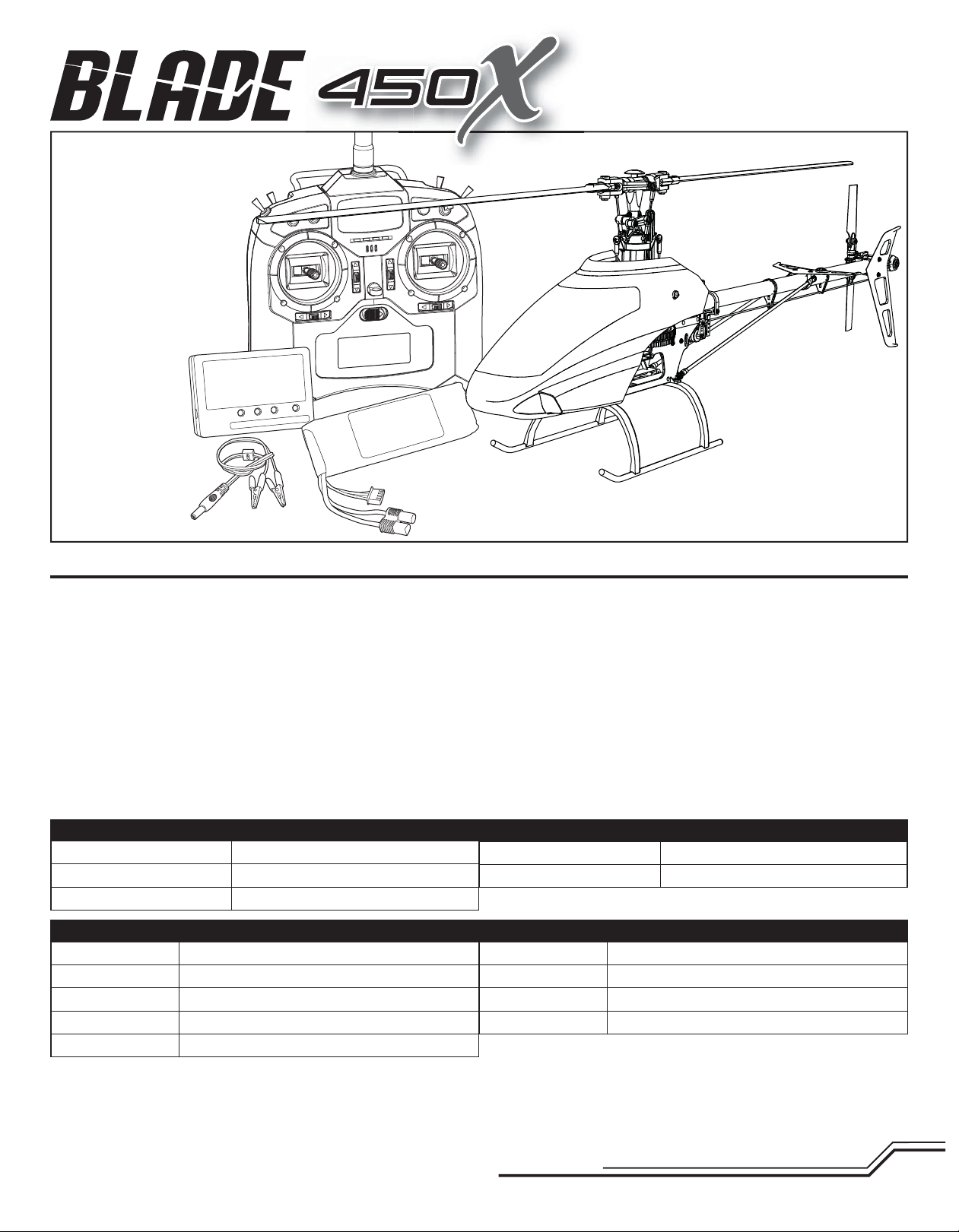
Box Contents:
®
• Blade 450 X
• 3S 11.1V 2200mAh 30C Li-Po Battery
• DC Li-Po Balancing Charger
• Spektrum DX6i Transmitter
• 4 AA Batteries
®
Table of Contents
First Flight Preparation ........................................................................................ 4
Flying Checklist .................................................................................................. 4
Charging Warnings............................................................................................... 4
Battery Charging .................................................................................................. 4
Low Voltage Cutoff (LVC) ...................................................................................... 5
Installing the Transmitter Batteries ...................................................................... 5
Transmitter Functions .......................................................................................... 5
Transmitter Mode Conversion............................................................................... 5
Transmitter Setup ................................................................................................ 6
Installing the Flight Battery .................................................................................. 6
Transmitter and Receiver Binding ......................................................................... 7
Throttle Hold ........................................................................................................ 7
Control Tests ........................................................................................................ 7
Pre-Flight Checklist ............................................................................................. 8
Flying the Blade 450 X ......................................................................................... 8
Specifi cations
Length
Height
Main Rotor Diameter
Airframe
Motor
Receiver
ESC
Battery
Blade® 450 X
440H Brushless Outrunner, 4200Kv
Spektrum™ AR7200BX with BeastX
35-Amp Brushless ESC
3S 11.1V 2200mAh 30C Li-Po
34.3 in (870mm)
8.8 in (225mm)
28.5 in (725mm)
®
Technology
Components
Gyro Gain Adjustment .......................................................................................... 9
Blade Helicopter Belt Tension ............................................................................... 9
Post-Flight Inspections and Maintenance ............................................................. 9
AR7200BX Default Blade 450 X Setup ................................................................ 10
AR7200BX Parameter Menu Tips ....................................................................... 10
AR7200BX Fine-tuning and Adjustment .............................................................. 11
Troubleshooting Guide ....................................................................................... 11
Limited Warranty ............................................................................................... 12
Warranty and Service Contact Information ......................................................... 12
FCC Information ................................................................................................. 13
IC Information .................................................................................................... 13
Compliance Information for the European Union ................................................. 13
Exploded Views .................................................................................................. 50
Parts List ........................................................................................................... 52
Optional Parts .................................................................................................... 54
Tail Rotor Diameter
Flying Weight
Charger
Transmitter
Swash Servos
Tail Servo
DC Li-Po Balancing Charger
Spektrum DX6i Transmitter
Digital Cyclic Servo 12 g Metal Gear
Digital Tail Servo 12 g Metal Gear
6.1 in (155mm)
25.3 oz (717 g)
To register your product online, visit www.bladehelis.com
3
EN
First Flight Preparation
• Remove and inspect contents
• Begin charging the fl ight battery
• Install the fl ight battery in the helicopter (once it has been fully charged)
• Program your computer transmitter
• Bind your transmitter (BNF only)
• Familiarize yourself with the controls
• Find a suitable area for fl ying
Charging Warnings
Flying Checklist
❏ Always turn the transmitter on fi rst
❏ Plug the fl ight battery into the lead from the ESC
❏ Allow the ESC to initialize and arm properly
❏ Fly the model
❏ Land the model
❏ Unplug the fl ight battery from the ESC
❏ Always turn the transmitter off last
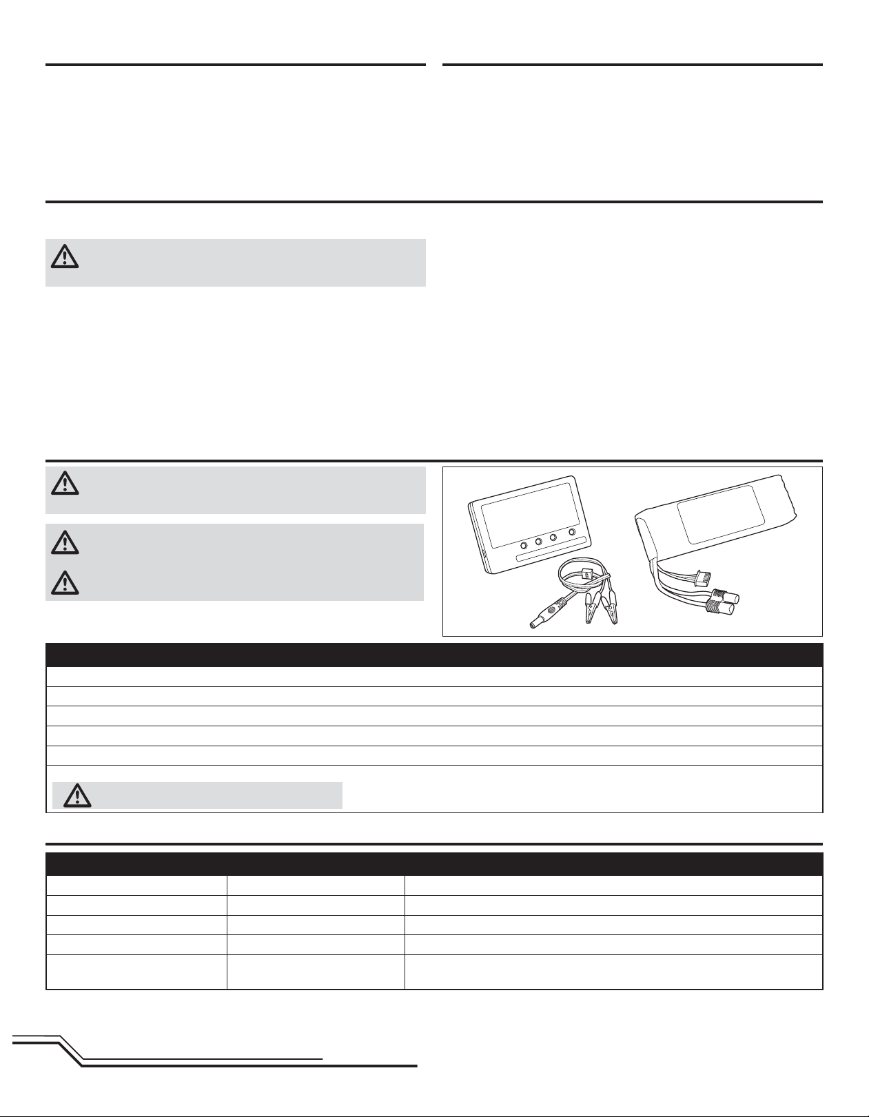
The Battery Charger (EFLC3115) included with your helicopter has been designed
to safely charge the Li-Po battery.
CAUTION: All instructions and warnings must be followed exactly.
Mishandling of Li-Po batteries can result in a fi re, personal injury and/or
property damage.
• By handling, charging or using the included Li-Po battery, you assume all risks
associated with lithium batteries.
• If at any time the battery begins to balloon or swell, discontinue use immediately. If
charging or discharging, discontinue and disconnect. Continuing to use, charge or
discharge a battery that is ballooning or swelling can result in fi re.
• Always store the battery at room temperature in a dry area for best results.
• Always transport or temporarily store the battery in a temperature range of 40–
120º F (5–49° C). Do not store battery or model in a car or direct sunlight. If stored
in a hot car, the battery can be damaged or even catch fi re.
• Always charge batteries away from fl ammable materials.
Battery Charging
CAUTION: Charge only batteries that are cool to the touch and are not
damaged. Look at the battery to make sure it is not damaged e.g.,
swollen, bent, broken or punctured.
CAUTION: Only use a charger specifi cally designed to charge a Li-Po
battery. Failure to do so could result in fi re causing injury or property
damage.
CAUTION: Never exceed the recommended charge rate.
• Always inspect the battery before charging.
• Always disconnect the battery after charging, and let the charger cool between
charges.
• Always constantly monitor the temperature of the battery pack while charging.
• ONLY USE A CHARGER SPECIFICALLY DESIGNED TO CHARGE LI-PO BATTERIES.
Failure to charge the battery with a compatible charger may cause a fi re resulting
in personal injury and/or property damage.
• Never discharge Li-Po cells to below 3V under load.
• Never cover warning labels with hook and loop strips.
• Never leave charging batteries unattended.
• Never charge batteries outside recommended levels.
• Never charge damaged batteries.
• Never attempt to dismantle or alter the charger.
• Never allow minors to charge battery packs.
• Never charge batteries in extremely hot or cold places (recommended between
40–120° F or 5–49° C) or place in direct sunlight.
The Battery Charging Process
1. Connect the charger to a 12V power source, noting proper polarity.
2. The CHARGE STATUS LED glows solid red.
3. Connect the battery balance lead to the charger. The balance connector is keyed to prevent reverse polarity.
4. The CELL STATUS LEDs glow solid green or yellow and the CHARGE STATUS LED glows solid red when the battery is charging.
5. Charging is complete when all LEDs glow solid red.
6. Always unplug the battery from the charger immediately upon completion of charging.
CAUTION: Overcharging a battery can cause a fi re.
LED Indications
Cell Status LEDs Charge Status LED Instruction
Off Red Solid Battery charger is powered. Li-Po battery is not connected
Yellow Red Solid Li-Po battery is connected. Charger is balancing the battery pack cells
Green Red Solid Li-Po battery is connected and charging
Red Red Solid Li-Po battery is connected and charging is complete
Off Blinking Red
No Li-Po battery connected: Voltage is outside the input voltage range
Li-Po battery connected: At least one battery cell voltage is below 2.6V
EN
4
Low Voltage Cuto (LVC)
The ESC will continuously lower power to the motor until complete shutdown
when the battery reaches 9V under load. This helps prevent over-discharge of the
Li-Po battery. Land immediately when the ESC activates LVC. Continuing to fl y after
LVC can damage the battery, cause a crash or both. Crash damage and batteries
damaged due to over-discharge are not covered under warranty.
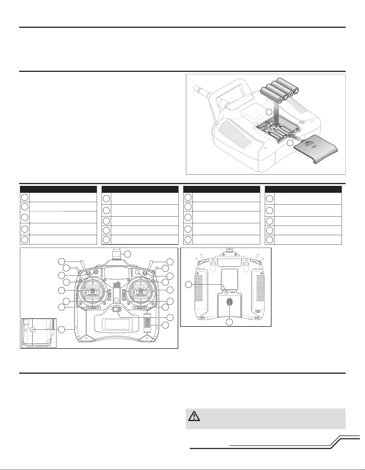
Installing the Transmitter Batteries
Replace transmitter batteries when the transmitter beeps and fl ashes a warning
screen.
Transmitter Functions
Function
A
Antenna
Throttle Cut
B
Mix/Throttle Hold (Mode 2)
C
Trainer/Bind (Mode 1)
Rudder Dual Rate (Mode 2)
D
Gear/Flight Mode (Mode 1)
Aileron Dual Rate
E
Aileron/Elevator Stick (Mode 2)
F
Aileron/Throttle Stick (Mode 1)
Elevator Trim (Mode 2)
G
Throttle Trim (Mode 1)
Aileron Trim
H
Roller
I
On/Off Switch
J
Function
Repeatedly fl ying the helicopter until LVC activates will damage the helicopter
battery.
Disconnect and remove the Li-Po battery from the aircraft after use to prevent
trickle discharge. During storage, make sure battery charge does not fall below 3V
per cell.
1
2
Function
Charge Port
K
L
Rudder Trim
Throttle Trim (Mode 2)
M
Elevator Trim (Mode 1)
Throttle/Rudder Stick (Mode 2)
N
Elevator/Rudder Stick (Mode 1)
Elevator Dual Rate
O
Gear/Flight Mode (Mode 2)
P
Rudder Dual Rate (Mode 1)
Trainer/Bind (Mode 2)
Q
Mix/Throttle Hold (Mode 1)
Flap/Gyro
R
S
Trainer Port
Battery Cover
T
Function
A
Q
P
O
R
N
M
L
K
D
C
E
B
F
G
H
J
I
Transmitter Mode Conversion
You can change transmitter modes between Mode 1 and Mode 2. This conversion
requires both a programming and a mechanical change.
Programming set up
1. Power on the transmitter.
2. Press the roller, scroll to Setup List and press the roller to access the Setup
List.
3. Select Copy/Reset in the Setup List. When the Copy/Reset menu screen opens,
select Reset.
S
T
The transmitter comes with a thin clear plastic fi lm applied to some front panels
for protection during shipping. Humidity and use may cause this fi lm to come off.
Carefully remove this fi lm as desired.
For more information on the transmitter, go to www.horizonhobby.com and click on
the support tab for the Spektrum DX6i to download the instruction manual.
4. Move the Aileron D/R switch forward and backward FOUR TIMES. A screen will
display Mode 1 and Mode 2.
5. Select the desired mode.
6. After you change the transmitter Mode in the Setup List, you will need to make
mechanical changes to the transmitter gimbals.
CAUTION: Always power off the transmitter and remove the batteries
before adjusting stick tension or friction straps. Not doing so could result
in property damage or injury.
5
EN

Mechanical Conversion
Mechanical conversion is required to change between Modes 1 and 2. The
mechanical conversion consists of the following steps:
Removing the Rear Case:
1. Power off the transmitter and remove the transmitter batteries.
2. Remove the six Phillips head screws that secure the rear transmitter case half.
3. Put the transmitter face down on a piece of foam or a towel and remove the
rear case.
CAUTION: Use care to not pull or disconnect any of the wires attached to
the back transmitter half.
Changing the Throttle Ratchet:
1. Locate the silver throttle friction straps on both gimbals.
2. To change the throttle ratchet, loosen the throttle strap so it does not touch
the throttle gimbal. Tighten the opposite throttle strap to engage the desired
throttle ratchet.
Adjusting the Elevator Centering Screw:
When changing between Modes 1 and 2, you must adjust the elevator centering
screw.
1. Hold the Elevator or Throttle stick in the full up or full down position when you
are adjusting the elevator centering screw. Holding the gimbal stick reduces
the load on the elevator centering mechanism and makes it easier to adjust
the centering screw.
2. Locate the gimbal where the elevator centering spring is engaged. Use a
Phillips screwdriver to tighten the elevator centering screw. Tightening the
screw will disengage the centering spring.
3. Using a Phillips screwdriver, loosen the opposite elevator centering screw until
the lever engages.
Transmitter Setup
Program your transmitter before attempting to bind or fl y the helicopter.
SETUP LIST ADJUST LIST
Model Type Reverse Swash Type Timer
THRO N
AILE N
HELI
Pos. Rate SW-F. Mode
0 77.0% NORM 0
1 77.0% STUNT 0
ELEV N
RUDD R
GYRO N
PITC R
Gyro
1 Servo 90 Degree
NORM 0% 30% 60% 60% 60%
STUNT 75% 75% 75% 75% 75%
HOLD 10% 10% 10% 10% 10%
Type: Down
Time: 4:00
Switch: Trainer
Throttle Curve
L234H
Switch Pos. D/R Expo
AILE
ELEV
RUDD
* Never use sub-trims or trims on AILE, ELEV or RUDD channels with the AR7200BX.
Dual Rate / Expo
NORM 30% 40% 50% 75% 100%
STUNT 0% 25% 50% 75% 100%
HOLD 0% 25% 50% 75% 100%
Travel Adjust
0 100% INH
1 85% INH
0 100% INH
1 85% INH
0 100% INH
1 85% INH
Pitch Curve
L234H
THRO 100%
AILE 100%
ELEV 100%
RUDD 100%
GYRO 100%
PITC 100%
Sub-Trim*
THRO 0
AILE 0*
ELEV 0*
RUDD 0*
GYRO 0
PITC 0
Swash Mix
INHIBIT
Installing the Flight Battery
1. Lower the throttle.
2. Power on the transmitter.
3. Center the throttle trim.
4. To allow the ESC to arm and to keep rotors from initiating at startup, turn on
throttle hold and normal fl ight mode before connecting the fl ight battery.
5. Attach hook material to the helicopter frame and loop material to the battery.
6. Install the fl ight battery on the helicopter frame. Secure the fl ight battery with a
hook and loop strap. Connect the battery cable to the ESC.
CAUTION: Always keep the power lead positioned AWAY from the
elevator servo. Failure to do so could cause the lead to get caught,
resulting in a crash causing property damage and injury.
CAUTION: Make sure the fl ight battery does not come in contact with the
motor. Failure to do so will cause the motor, ESC and battery to overheat,
resulting in a crash causing property damage and injury.
7. Do not move the helicopter until the AR7200BX initializes. The swashplate will
move up and down, indicating that the unit is ready. The AR7200BX will also
emit a solid BLUE Status LED when it is ready.
8. The helicopter motor will emit 2 tones, incdicating the ESC is armed.
CAUTION: Always disconnect the Li-Po battery from the aircraft
receiver when not fl ying to avoid over-discharging the battery. Batteries
discharged to a voltage lower than the lowest approved voltage may become
damaged, resulting in loss of performance and potential fi re when batteries are
charged.
EN
6
 Loading...