

Page 1

Instruction Manual
Page 2
NOTICE
All instructions, warranties and other collateral documents are subject to change at the sole discretion of Horizon
Hobby, LLC. For up-to-date product literature, visit horizonhobby.com and click on the support tab for this product.
Meaning of Special Language
The following terms are used throughout the product literature to indicate various levels of potential harm when
operating this product:
NOTICE: Procedures, which if not properly followed, create a possibility of physical property damage AND a little or no
possibility of injury.
CAUTION: Procedures, which if not properly followed, create the probability of physical property damage AND a possibility of serious injury.
WARNING: Procedures, which if not properly followed, create the probability of property damage, collateral damage,
and serious injury OR create a high probability of superfi cial injury.
WARNING: Read the ENTIRE instruction manual to become familiar with the features of the product before
operating. Failure to operate the product correctly can result in damage to the product, personal property and
cause serious injury.
This is a sophisticated hobby product. It must be operated with caution and common sense and requires some basic
mechanical ability. Failure to operate this Product in a safe and responsible manner could result in injury or damage
to the product or other property. This product is not intended for use by children without direct adult supervision. Do
not use with incompatible components or alter this product in any way outside of the instructions provided by Horizon
Hobby, LLC. This manual contains instructions for safety, operation and maintenance. It is essential to read and follow
all the instructions and warnings in the manual, prior to assembly, setup or use, in order to operate correctly and avoid
damage or serious injury.
Age Recommendation: Not for children under 14 years. This is not a toy.
Safety Precautions and Warnings
• Always keep a safe distance in all directions around
your model to avoid collisions or injury. This model is
controlled by a radio signal subject to interference from
many sources outside your control. Interference can
cause momentary loss of control.
• Always operate your model in open spaces away from
full-size vehicles, traffi c and people.
• Always carefully follow the directions and warnings
for this and any optional support equipment (chargers,
rechargeable battery packs, etc.).
• Always keep all chemicals, small parts and anything
electrical out of the reach of children.
• Always avoid water exposure to all equipment not
specifi cally designed and protected for this purpose.
Moisture causes damage to electronics.
• Never place any portion of the model in your mouth as it
could cause serious injury or even death.
• Never operate your model with low transmitter batteries.
• Always keep aircraft in sight and under control.
• Always move the throttle fully down at rotor strike.
• Always use fully charged batteries.
• Always keep transmitter powered on while aircraft is
powered.
• Always remove batteries before disassembly.
• Always keep moving parts clean.
• Always keep parts dry.
• Always let parts cool after use before touching.
• Always remove batteries after use.
• Never operate aircraft with damaged wiring.
• Never touch moving parts.
WARNING AGAINST COUNTERFEIT PRODUCTS: If you ever need to replace a Spektrum compo-
nent found in a Horizon Hobby product, always purchase from Horizon Hobby, LLC or a Horizon
Hobby authorized dealer to ensure authentic high-quality Spektrum product. Horizon Hobby, LLC disclaims
all support and warranty with regards, but not limited to, compatibility and performance of counterfeit
products or products claiming compatibility with DSM or Spektrum.
EN
2
Page 3
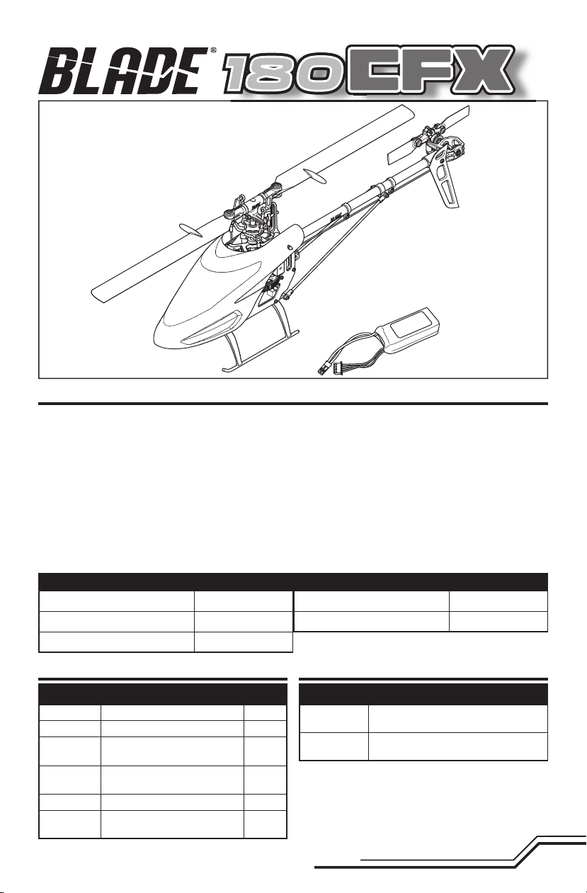
Box Contents
• Blade® 180 CFX
• 450mAh 3S 11.1V 30C Li-Po Battery
Table of Contents
First Flight Preparation ..................................................... 4
Flying Checklist ...............................................................4
Charging Warnings........................................................... 4
Battery Charging .............................................................. 4
Transmitter Setup ............................................................ 4
Installing the Flight Battery ..............................................6
Transmitter and Receiver Binding .....................................7
Throttle Hold .................................................................... 7
Control Tests .................................................................... 7
Blade 180 CFX Pre-Flight Checklist .................................. 9
Flying the Blade 180 CFX ................................................. 9
Low Voltage Cutoff (LVC) ................................................ 10
Specifi cations
Length
Height
Main Rotor Diameter
13.4 in (340mm)
5.1 in (130mm)
14.2 in (360mm)
Gyro Gain Adjustment ....................................................10
Post-Flight Inspections and Maintenance ....................... 10
Blade 180 CFX Troubleshooting Guide ........................... 11
Exploded View .............................................................. 12
Replacement Parts ......................................................... 13
Optional Parts ................................................................ 13
Limited Warranty ........................................................... 13
Warranty and Service Contact Information .....................15
FCC Information ............................................................. 15
IC Information ................................................................ 15
Compliance Information for the European Union ............. 15
Tail Rotor Diameter
Flying Weight
3.6 in (90.5mm)
6.7 oz (190 g)
Included Items Required Items
Components
Motor
ESC
Flybarless
Unit
Swash
Servos
Tail Servo
Battery
Brushless Outrunner
Castle Creations 15A installed
Spektrum™ AR6335 6-Channel
®
AS3X
Nanolite Receiver
Nanolite High-Speed installed
DS76T Sub-Micro Digital Tail installed
450mAh 3S 11.1V 30C Li-Po
Battery
installed
installed
included
Charger
Transmitter
To register your product online, visit www.bladehelis.com
Dynamite
AC Charger (DYNC2005)
Full Range DSM2
transmitter (DX6i and up)
3
Components
®
Prophet™ Sport Li-Po 35W
®
/DSMX® technology
EN
Page 4
First Flight Preparation
• Remove and inspect contents
• Begin charging the fl ight battery
• Install the fl ight battery in the helicopter
(once it has been fully charged)
• Program your computer transmitter
• Bind your transmitter
• Familiarize yourself with the controls
• Find a suitable area for fl ying
Charging Warnings
CAUTION: All instructions and warnings must be
followed exactly. Mishandling of Li-Po batteries can
result in a fi re, personal injury and/or property damage.
• NEVER LEAVE THE POWER SUPPLY, CHARGER AND BATTERY UNATTENDED DURING USE.
• NEVER CHARGE BATTERIES OVERNIGHT.
• By handling, charging or using the included Li-Po battery,
you assume all risks associated with lithium batteries.
• If at any time the battery begins to balloon or swell,
discontinue use immediately. If charging or discharging,
discontinue and disconnect. Continuing to use, charge or
discharge a battery that is ballooning or swelling can result
in fi re.
• Always store the battery at room temperature in a dry area
for best results.
• Always transport or temporarily store the battery in a
temperature range of 40–120º F (5–49° C). Do not store the
battery or model in a car or direct sunlight. If stored in a hot
car, the battery can be damaged or even catch fi re.
Battery Charging
Choose a charger designed to balance charge 3S Li-Po
batteries. We recommend the Dynamite Prophet Sport Li-Po
35W AC Charger (DYNC2005). Refer to your charger manual
for charging instructions.
Transmitter Setup
Program your transmitter before attempting to bind or
fl y the helicopter. Transmitter programming values are
shown below for the Spektrum DX6i, DX7/DX7se, DX6, DX7s,
Flying Checklist
❏ Always turn the transmitter on fi rst
❏ Plug the fl ight battery into the lead from the ESC
❏ Allow the receiver and ESC to initialize and arm
properly
❏ Fly the model
❏ Land the model
❏ Unplug the fl ight battery from the ESC
❏ Always turn the transmitter off last
• Always charge batteries away from fl ammable materials.
• Always inspect the battery before charging.
• Always disconnect the battery after charging, and let the
charger cool between charges.
• Always constantly monitor the temperature of the battery
pack while charging.
• ONLY USE A CHARGER SPECIFICALLY DESIGNED TO
CHARGE LI-PO BATTERIES. Failure to charge the battery
with a compatible charger may cause a fi re resulting in
personal injury and/or property damage.
• Never discharge Li-Po cells to below 3V under load.
• Never cover warning labels with hook and loop strips.
• Never charge batteries outside recommended levels.
• Never charge damaged batteries.
• Never attempt to dismantle or alter the charger.
• Never allow minors to charge battery packs.
• Never charge batteries in extremely hot or cold places
(recommended between 40–120° F (5–49° C)) or place in
direct sunlight.
DX8, DX9 and DX18. The fi les for models using SpektrumTM
transmitters with AirWare™ software are also available for
download online in the Spektrum Community.
DX6i
EN
SETUP LIST
Model Type
HELI
Reverse
THRO N
AILE N
ELEV N
RUDD N
GYRO N
PITC R
Swash Type
1 Servo 90
Timer
3:00
ADJUST LIST
Thro Curve
NORM 0% 25% 25% 25% 25%
STUNT 100% 100% 100% 100% 100%
HOLD 0% 0% 0% 0% 0%
Pitc Curve
NORM 30% 40% 50% 75% 100%
STUNT 0% 25% 50% 75% 100%
HOLD 0% 25% 50% 75% 100%
Travel Adj
THRO Low: 100% Hi: 100%
AILE 100%
ELEV 100%
RUDD 100%
GYRO 100%
PITC 100%
Gyro
Rate SW-F. Mode
NORM 50%
STUNT 50%
4
Page 5

DX7/DX7se
SYSTEM LIST
Model Type
HELI
Swatch Type
1 Servo 90
FUNCTION MODE
D/R & EXP
0-AILE 100% 0%
0-ELEV 100% 0%
0-RUDD 100% INH
1-AILE 85% 0%
1-ELEV 85% 0%
1-RUDD 85% INH
Thro Curve
NORM 0% 25% 25% 25% 25%
ST-1 75% 75% 75% 75% 75%
ST-2 100% 100% 100% 100% 100%
HOLD 0% 0% 0% 0% 0%
Pitc Curve
NORM 30% INH 50% INH 100%
ST-1 0% INH 50% INH 100%
ST-2 0% INH 50% INH 100%
HOLD 0% INH 50% INH 100%
Travel Adj
THRO Low: 100% Hi: 110%
AILE 100%
ELEV 100%
RUDD 100%
GEAR 100%
PIT. 100%
DX6/DX7s/DX8/DX9/DX18
SYSTEM SETUP
Model Type
HELI
Swash Type
1 Servo Normal
F-Mode Setup
Flight Mode: F Mode
Hold: Hold
Frame Rate
22ms
DSMX
FUNCTION LIST
D/R & Expo
0-AILE 100% 0%
0-ELEV 100% 0%
0-RUDD 100% 0%
1-AILE 85% 0%
1-ELEV 85% 0%
1-RUDD 85% 0%
2-AILE 85% 0%
2-ELEV 85% 0%
2-RUDD 85% 0%
SERVO SETUP
Travel
THRO Low: 100% Hi: 110%
AILE 100%
ELEV 100%
RUDD 100%
GEAR 100%
PIT. 100%
Reversing SW
THRO N RUDD N
AILE N GEAR N
ELEV N PIT. N
Gyro SENS
AUTO F.MODE
STNT 50%
HOLD 50%
Throttle Curve
NORM 0% 25% 25% 25% 25%
ST-1 75% 75% 75% 75% 75%
ST-2 (DX8, 9, 18) 100% 100% 100% 100% 100%
HOLD 0% 0% 0% 0% 0%
Pitch Curve
NOR 30% 40% 50% 75% 100%
ST-1 0% 25% 50% 75% 100%
ST-2 (DX8/18 only) 0% 25% 50% 75% 100%
HOLD 0% 25% 50% 75% 100%
Reverse
THRO N
AILE N
ELEV N
RUDD N
GEAR N
PIT. N
Timer
3:00
Timer
MODE Countdown
TIME 3:00 Tone/Vibe
START Throttle Cut
POS 25
Gyro
SW F Mode
CH Gear
NORMAL/POS 0 75%
STUNT 1/POS 1 75%
STUNT 2/POS 2 75%
HOLD 75%
5
EN
Page 6

Installing the Flight Battery
1. Lower the throttle.
2. Power on the transmitter.
3. Center the throttle trim.
4. To allow the ESC to arm and to keep rotors from initiating at startup, turn on throttle hold and normal fl ight
mode before connecting the fl ight battery. Please refer
to your transmitter manual for more information on
programming throttle hold and normal fl ight mode.
5. Attach hook material to the helicopter frame and loop
material to the battery.
6. Install the fl ight battery on the helicopter frame. Secure
the fl ight battery with a hook and loop strap. Connect
the battery cable to the ESC.
CAUTION: Always disconnect the Li-Po battery from the aircraft receiver when not fl ying to avoid over-discharging
the battery. Batteries discharged to a voltage lower than the lowest approved voltage may become damaged,
resulting in loss of performance and potential fi re when batteries are charged.
CAUTION: Always keep the power lead posi-
tioned AWAY from the elevator servo. Failure to
do so could cause the lead to get caught and will result
in crash causing property damage and injury.
CAUTION: Make sure the fl ight battery does not
come in contact with the motor. Failure to do
so will cause the motor, ESC and battery to overheat,
resulting in crash, causing property damage and injury.
7. Do not move the helicopter until the receiver initializes.
The LED on the receiver glows solid when the helicopter is initialized.
8. The helicopter motor will emit 2 tones, indicating the
ESC is armed.
EN
6
Page 7

Transmitter and Receiver Binding
Binding is the process of programming the receiver to
recognize the GUID (Globally Unique Identifi er) code of a
single specifi c transmitter. You need to ‘bind’ your chosen
Binding Procedure
1. Disconnect the fl ight battery from the helicopter.
2. Refer to the Transmitter Setup Table to correctly set up your transmitter.
3. Lower the throttle and throttle trim to the lowest position.
4. Power off the transmitter and move all switches to the 0 position.
5. Install the bind plug in the bind port extension.
6. Connect the fl ight battery to the ESC. The receiver LED fl ashes, indicating it is in bind mode.
7. Put the transmitter into bind mode while powering on the transmitter.
8. Release the bind button/switch after 2–3 seconds. The helicopter is bound when the LED on the receiver turns solid.
9. Disconnect the fl ight battery and remove the bind plug. Store the bind plug in a convenient place.
NOTICE: Remove the bind plug to prevent the system from
entering bind mode the next time the power is turned on.
If you encounter problems, obey binding instructions and
refer to transmitter troubleshooting guide for other
Spektrum™ DSM2/DSMX technology equipped aircraft
transmitter to the receiver for proper operation.
instructions. If needed, contact the appropriate Horizon
Product Support offi ce. For a list of compatible DSM
transmitters, please visit www.bindnfl y.com.
Throttle Hold
Throttle hold only turns off the motor on an electric helicopter. You must maintain pitch and direction control.
The blades will spin if throttle hold is OFF. For safety, turn
throttle hold ON any time you need to touch the helicopter
or check the direction controls.
Throttle hold is also used to turn off the motor if the
helicopter is out of control, in danger of crashing, or both.
Please refer to your transmitter manual for more
information on programming throttle hold.
Control Tests
Test the controls prior to the fi rst fl ight to ensure the servos, linkages and parts operate correctly. Turn on Throttle Hold
when doing the control tests.
Elevator
Side View
Aileron
Rear View
Side View
Rear View
7
EN
Page 8

Rudder
Collective Pitch
Motor Control Test
Place the helicopter outdoors on a clean, fl at and level
surface (concrete or asphalt) free of obstructions. Always
stay clear of moving rotor blades.
1. The motor beeps twice when the helicopter’s ESC
arms properly. Before you continue, confi rm that
TH HOLD is ON.
WARNING: The motor will spin when throttle is
increased while TH HOLD is OFF.
2. Check the swashplate directions to ensure they are
moving in the correct direction. Please refer to the
diagrams above for reference.
WARNING: Stay at least 30 feet (10 meters)
away from the helicopter when the motor is
running. Do not attempt to fl y the helicopter at this time.
Side ViewSide View
3. Ensure the throttle is lowered completely. Turn throttle
hold off at this time and confi rm the transmitter is still
set to normal fl ight mode. Slowly increase the throttle
until the blades begin to spin. The main blades spin
clockwise when viewing the helicopter from the top.
The tail rotor blades spin counterclockwise when
viewing the helicopter from the right-hand side.
NOTICE: If the main rotor blades are spinning counterclockwise, reduce the throttle to low immediately.
Turn throttle hold on. Disconnect the battery from the
helicopter and reverse any two motor wire connections
to the ESC and repeat the motor control test.
EN
8
Page 9

Blade 180 CFX Pre-Flight Checklist
❏ Check all screws to ensure that they are tight
❏ Check main and tail blades to ensure they are not
damaged
❏ Check all links to make sure they move freely, but do
not pop off easily
❏ Check that fl ight battery and transmitter battery are
fully charged
❏ Check all wires to ensure that they are not cut,
pinched, or chaffed and are properly secured
Flying the Blade 180 CFX
❏ Check all wire connections
❏ Check gears to make sure no teeth are missing
❏ Do a complete control test
❏ Check that the servos are functioning properly
❏ Check to make sure the fl ight battery is properly
secured
❏ Check to make sure the receiver is properly secured
Consult local laws and ordinances before choosing a
location to fl y your aircraft.
Select a large, open area away from people and objects.
Your fi rst fl ights should be outdoors in low-wind conditions. Always stay at least 30 feet (10 meters) away from
the helicopter when it is fl ying.
The Blade 180 CFX is intended to be fl own outdoors or
inside a large gymnasium.
Takeoff
Deliberately increase throttle and establish a hover at least
24” (0.6 meter) high, outside of ground effect.
CAUTION: Do not give any aileron, elevator
or rudder commands before takeoff or the
helicopter may crash during takeoff.
Flying
The helicopter lifts off the ground when the rotor head
reaches a suitable speed. Establish a low-level hover
outside of ground effect to verify proper operation of your
helicopter. You must not set any trim; the fl ybarless design
of the Blade 180 CFX renders trim unnecessary. Setting
trim or sub-trim can cause an unwanted drift or rotation of
the helicopter.
First fl ights should be performed in normal mode and low
cyclic and rudder dual rates until you are familiar with the
fl ying manner of the Blade 180 CFX. Discover the rates
that fi t your fl ying style.
CAUTION: Always fl y the helicopter with your
back to the sun and the wind to prevent loss of
fl ight control.
Landing
Establish a low level hover. Deliberately lower the throttle
until the helicopter lands. Do not give any aileron, elevator
or rudder commands when the helicopter is landing.
When the helicopter is in stunt mode:
• The rotor head speed is constant.
• The main rotor will increase negative pitch as the
throttle/collective stick is moved from the middle
stick position to the low stick position. Negative pitch
allows the helicopter to fl y upside down and perform
aerobatics.
Change between stunt and idle up modes in a hover with
the throttle near the hovering stick position.
The helicopter may go up or down when you change
between modes due to the difference in the throttle and
pitch curves.
If the cyclic control is too slow or too fast, adjust the transmitter dual rates, expo or throttle curve to fi t your liking.
For advanced AS3X settings please go to
Bladehelis.com and refer to the 180 CFX page.
9
EN
Page 10

Low Voltage Cuto (LVC)
Once the battery reaches 9V under load, the ESC will
continuously lower power supplied to the motor until
complete shutdown occurs. This helps prevent overdischarge of the Li-Po battery. Land immediately once the
ESC activates LVC. Continuing to fl y after LVC can damage
the battery, cause a crash or both. Crash damage and
batteries damaged due to over-discharge are not covered
under warranty.
Repeatedly fl ying the helicopter until LVC activates will
damage the helicopter battery.
Disconnect and remove the Li-Po battery from the aircraft
after use to prevent trickle discharge. During storage,
make sure the battery charge does not fall below 3V per
cell.
Gyro Gain Adjustment
If the tail wags or oscillates, lower the gain on the gyro.
On your transmitter’s gyro menu, decrease the gyro gain
values a small amount until the helicopter is stable within
a particular fl ight mode.
If the tail is drifting while hovering, increase the gain
on the gyro. On your transmitter, increase the gyro gain
values a small amount at a time until the tail starts to wag/
oscillate. Afterwards, reduce the gain until the tail stops
wagging/oscillating within a particular fl ight mode.
Post-Flight Inspections and Maintenance
Ball Links
Cleaning
Bearings Replace bearings when they become notchy (sticky in places when turning) or draggy.
Wiring
Fasteners
Rotors
Gyro
Make sure the plastic ball link holds the control ball, but is not tight (binding) on the ball.
When a link is too loose on the ball, it can separate from the ball during fl ight and cause a
crash. Replace worn ball links before they fail.
Make sure the battery is not connected before cleaning. Remove dust and debris with a
soft brush or a dry lint-free cloth.
Make sure the wiring does not contact moving parts. Replace damaged wiring and loose
connectors.
Make sure there are no loose screws, other fasteners or connectors. Do not over tighten
metal screws in plastic parts. Tighten screw so parts are mated together, then turn screw
only 1/8th of a turn more.
Make sure there is no damage to rotor blades and other parts which move at high speed.
Damage to these parts includes cracks, burrs, chips or scratches. Replace damaged parts
before fl ying.
Make sure the receiver is securely attached to the frame. Replace the double-sided tape
when necessary. The helicopter will crash if the receiver separates from the helicopter
frame.
EN
10
Page 11

Blade 180 CFX Troubleshooting Guide
Problem Possible Cause Solution
Helicopter will not bind
to the transmitter (during binding)
Helicopter will not
link to the transmitter
(after binding)
The receiver will not
initialize
Helicopter will not
respond to the throttle
but responds to other
controls
Helicopter power is
lacking
Helicopter will not
lift off
The helicopter tail
spins out of control
The helicopter wobbles in fl ight
Low fl ight battery or transmitter battery voltage
The receiver is not in bind mode
Transmitter is not in bind mode
Transmitter too close to the helicopter
during the binding process
Helicopter is bound to a different model
memory (ModelMatch™ radios only)
Flight battery/Transmitter battery
charge is too low
The helicopter was moved during
initialization
The transmitter is powered off Power on the transmitter
Controls are not centered
Throttle not at idle and/or throttle trim
is too high
The transmitter is not in normal mode
or throttle hold is on
The motor is not connected to the ESC
or the motor wires are damaged
Flight battery charge is too low Replace or recharge fl ight battery
Throttle channel is reversed
Flight battery has low voltage Fully charge the fl ight battery
Flight battery is old or damaged Replace the fl ight battery
Flight battery cells are unbalanced
Excessive current is being drawn
through the BEC
Main rotor head is not spinning in the
correct direction
Transmitter settings are not correct Check throttle and pitch curve settings
Flight battery has low voltage Fully charge the fl ight battery
Main rotor blades are installed back-
wards
Rudder control and/or sensor direction
reversed
Tail servo is damaged
Inadequate control arm throw
Headspeed is too low
Dampers are worn Replace the main rotor head dampers
Fully charge or replace the fl ight battery and/or transmitter batteries
Make sure the bind plug is connected to the receiver
bind port extension
Refer to your transmitter's instruction manual for binding
instructions
Power off the transmitter. Move the transmitter to a
larger distance from the helicopter. Disconnect and
reconnect the fl ight battery to the helicopter and follow
binding instructions
Disconnect the fl ight battery. Select the correct model
memory on the transmitter. Reconnect the fl ight battery
Replace or recharge batteries
Lay the helicopter on its side during initialization if windy
Center elevator, aileron and rudder controls. Make sure
the throttle is at idle
Lower the throttle stick and throttle trim to the lowest
settings
Make sure the transmitter is in normal mode and throttle
hold is off
Connect the motor wires to the ESC and check motor
wires for damage
Power down helicopter. Reverse the throttle channel on
the transmitter
Fully charge the fl ight battery, allowing the charger time
to balance the cells
Check all servos and the helicopter motor for damage
Make sure the main rotor head is spinning clockwise.
Refer to motor control test
Install the main rotor blades with the thicker side as the
leading edge
Make sure the rudder control and the rudder sensor are
operating in the correct direction
Check the rudder servo for damage and replace if necessary
Check the rudder control arm for adequate travel and
adjust if necessary
Increase the helicopter's head speed via your transmitter
settings and/or using a freshly charged fl ight pack
11
EN
Page 12

Exploded View
4
3
5
5
38
3
39
2
13
35
9
14
43
43
8
17
15
46
18
19
32
37
4
39
1
11
8
36
10
12
43
45
32
36
37
10
6
7
13
14
34
33
41
25
22
31
23
EN
24
20
39
22
21
39
40
23
44
26
25
26
26
28
29
28
26
20
30
28
32
12
Page 13

Replacement Parts
# Part # Description
1 BLH3401 Main Blade Grips: 180 CFX
2 BLH3402 Main Blades: 180 CFX
3 BLH3403 Feathering Spindle Set: 180 CFX
4 BLH3404 Main Rotor Head Block: 180 CFX
5 BLH3405 Rotor Head Linkage Set: 180 CFX
6 BLH3406 Swashplate: 180 CFX
7 BLH3407 Main Shaft Set: 180 CFX
8 BLH3408 Main Gear: 180 CFX
9 BLH3409 Stock Canopy: 180 CFX
10 BLH3410 Servo Control Linkage Set: 180 CFX
11 BLH3411 Main Bearing Block Set: 180 CFX
12 BLH3412 Anti-Rotation Bracket: 180 CFX
13 BLH3413 Carbon Fiber Main Frame: 180 CFX
14 BLH3414 Body Post Set: 180 CFX
15 BLH3415 Battery Tray: 180 CFX
16 BLH3416 Motor Mount: 180 CFX
17 BLH3417 Brushless Main Motor: 180 CFX
18 BLH3418 Bottom Plate: 180 CFX
19 BLH3419 Landing Gear: 180 CFX
20 BLH3420 Front Tail Boom Case: 180 CFX
21 BLH3421 Tail Pinion Gear/Shaft: 180 CFX
22 BLH3422 Bevel Gear: 180 CFX
23 BLH3423 Torque Tube Gear: 180 CFX
24 BLH3424 Tail Boom (2): 180 CFX
Optional Parts
# Part # Description
25 BLH3425 Torque Tube (2): 180 CFX
26 BLH3426 Boom Support Set: 180 CFX
27 BLH3427 Tail Pushrod (2): 180 CFX
28 BLH3428 Tail Pushrod Guide Set: 180 CFX
29 BLH3429 Tail Boom Clamp: 180 CFX
30 BLH3430 Vertical Fin: 180 CFX
31 BLH3431 Tail Case Set: 180 CFX
32 BLH3432 Tail Shaft and Hub: 180 CFX
33 BLH3433 Tail Pitch Bellcrank: 180 CFX
34 BLH3434 Tail Pitch Slider: 180 CFX
35 BLH3435 Tail Grip Set: 180 CFX
36 BLH3436 Tail Grip Bearing Set: 180 CFX
37 BLH3437 Tail Blade Set: 180 CFX
38 BLH3438
39 BLH3439
40 BLH3440
41 BLH3441
42 EFLB4503SJ30
43 SPMSH2060 Nanolite High-Speed Heli Servo
44 EFLRDS76TJ 7.6g Sub-Micro Digital Tail Servo JST
45 SPMAR6335
46 BLH3442 Castle Creations 15A Blade ESC
2.5x6x2.8mm Thrust Bearing: 180 CFX
2.5x6x1.8mm Radial Bearing: 180 CFX
5x8x2mm Radial Bearing: 180 CFX
2.5x6x2.6mm Flanged Bearing: 180
CFX
450mAh 3S 11.1V 30C
Li-Po Battery
AR6335 6-Channel AS3X Nanolite
Receiver
Part # Description
BLH3401A Aluminum Main Blade Grips: 180 CFX
BLH3402C Carbon Fiber Main Blades: 180 CFX
BLH3404A Aluminum Main Rotor Head Block: 180 CFX
BLH3406A Aluminum Swashplate: 180 CFX
BLH3409B Fiberglass Canopy: 180 CFX
BLH3431A Aluminum Tail Case Set: 180 CFX
BLH3433A Aluminum Tail Pitch Bellcrank: 180 CFX
Limited Warranty
What this Warranty Covers
Horizon Hobby, LLC, (Horizon) warrants to the original
purchaser that the product purchased (the “Product”) will be
free from defects in materials and workmanship at the date
of purchase.
What is Not Covered
This warranty is not transferable and does not cover (i)
cosmetic damage, (ii) damage due to acts of God, accident,
misuse, abuse, negligence, commercial use, or due to
improper use, installation, operation or maintenance, (iii)
modi cation of or to any part of the Product, (iv) attempted
service by anyone other than a Horizon Hobby authorized
Part # Description
DYNC2005 Prophet Sport Li-Po 35W AC Charger
DX6i DSMX 6-Channel Transmitter Only
DX6 DSMX 6-Channel Transmitter Only
DX7s DSMX 7-Channel Transmitter Only
DX8 DSMX 8-Channel Transmitter Only
DX9 DSMX 9-Channel Transmitter Only
DX18 DSMX 18-Channel Transmitter Only
service center, (v) Product not purchased from an authorized
Horizon dealer, or (vi) Product not compliant with applicable
technical regulations.
OTHER THAN THE EXPRESS WARRANTY ABOVE, HORIZON
MAKES NO OTHER WARRANTY OR REPRESENTATION, AND
HEREBY DISCLAIMS ANY AND ALL IMPLIED WARRANTIES,
INCLUDING, WITHOUT LIMITATION, THE IMPLIED
WARRANTIES OF NON-INFRINGEMENT, MERCHANTABILITY
AND FITNESS FOR A PARTICULAR PURPOSE. THE
PURCHASER ACKNOWLEDGES THAT THEY ALONE HAVE
DETERMINED THAT THE PRODUCT WILL SUITABLY MEET THE
REQUIREMENTS OF THE PURCHASER’S INTENDED USE.
13
EN
Page 14

Purchaser’s Remedy
Horizon’s sole obligation and purchaser’s sole and exclusive
remedy shall be that Horizon will, at its option, either (i)
service, or (ii) replace, any Product determined by Horizon
to be defective. Horizon reserves the right to inspect any
and all Product(s) involved in a warranty claim. Service or
replacement decisions are at the sole discretion of Horizon.
Proof of purchase is required for all warranty claims.
SERVICE OR REPLACEMENT AS PROVIDED UNDER THIS
WARRANTY IS THE PURCHASER’S SOLE AND EXCLUSIVE
REMEDY.
Limitation of Liability
HORIZON SHALL NOT BE LIABLE FOR SPECIAL, INDIRECT,
INCIDENTAL OR CONSEQUENTIAL DAMAGES, LOSS OF
PROFITS OR PRODUCTION OR COMMERCIAL LOSS IN ANY
WAY, REGARDLESS OF WHETHER SUCH CLAIM IS BASED
IN CONTRACT, WARRANTY, TORT, NEGLIGENCE, STRICT
LIABILITY OR ANY OTHER THEORY OF LIABILITY, EVEN IF
HORIZON HAS BEEN ADVISED OF THE POSSIBILITY OF SUCH
DAMAGES. Further, in no event shall the liability of Horizon
exceed the individual price of the Product on which liability
is asserted. As Horizon has no control over use, setup,
nal assembly, modi cation or misuse, no liability shall be
assumed nor accepted for any resulting damage or injury.
By the act of use, setup or assembly, the user accepts all
resulting liability. If you as the purchaser or user are not
prepared to accept the liability associated with the use of
the Product, purchaser is advised to return the Product
immediately in new and unused condition to the place of
purchase.
Law
These terms are governed by Illinois law (without regard to
con ict of law principals). This warranty gives you speci c
legal rights, and you may also have other rights which vary
from state to state. Horizon reserves the right to change or
modify this warranty at any time without notice.
WARRANTY SERVICES
Questions, Assistance, and Services
Your local hobby store and/or place of purchase cannot
provide warranty support or service. Once assembly, setup
or use of the Product has been started, you must contact
your local distributor or Horizon directly. This will enable
Horizon to better answer your questions and service you in
the event that you may need any assistance. For questions or
assistance, please visit our website at
www.horizonhobby.com, submit a Product Support Inquiry, or
call the toll free telephone number referenced in the Warranty
and Service Contact Information section to speak with a
Product Support representative.
Inspection or Services
If this Product needs to be inspected or serviced and is
compliant in the country you live and use the Product in,
please use the Horizon Online Service Request submission
process found on our website or call Horizon to obtain a
Return Merchandise Authorization (RMA) number. Pack the
Product securely using a shipping carton. Please note that
original boxes may be included, but are not designed to
withstand the rigors of shipping without additional protection.
Ship via a carrier that provides tracking and insurance for
lost or damaged parcels, as Horizon is not responsible for
merchandise until it arrives and is accepted at our facility.
An Online Service Request is available at http://www.
horizonhobby.com/content/_service-center_render-servicecenter. If you do not have internet access, please contact
Horizon Product Support to obtain a RMA number along with
instructions for submitting your product for service. When
calling Horizon, you will be asked to provide your complete
name, street address, email address and phone number
where you can be reached during business hours. When
sending product into Horizon, please include your RMA
number, a list of the included items, and a brief summary
of the problem. A copy of your original sales receipt must
be included for warranty consideration. Be sure your name,
address, and RMA number are clearly written on the outside
of the shipping carton.
NOTICE: Do not ship Li-Po batteries to Horizon. If you have
any issue with a Li-Po battery, please contact the appropriate
Horizon Product Support of ce.
Warranty Requirements
For Warranty consideration, you must include your
original sales receipt verifying the proof-of-purchase
date. Provided warranty conditions have been met, your
Product will be serviced or replaced free of charge. Service or
replacement decisions are at the sole discretion of Horizon.
Non-Warranty Service
Should your service not be covered by warranty,
service will be completed and payment will be
required without notifi cation or estimate of the
expense unless the expense exceeds 50% of the retail
purchase cost. By submitting the item for service you
are agreeing to payment of the service without noti cation.
Service estimates are available upon request. You must
include this request with your item submitted for service.
Non-warranty service estimates will be billed a minimum
of ½ hour of labor. In addition you will be billed for return
freight. Horizon accepts money orders and cashier’s checks,
as well as Visa, MasterCard, American Express, and Discover
cards. By submitting any item to Horizon for service, you are
agreeing to Horizon’s Terms and Conditions found on our
website http://www.horizonhobby.com/content/_servicecenter_render-service-center.
ATTENTION: Horizon service is limited to Product
compliant in the country of use and ownership.
If received, a non-compliant Product will not be
serviced. Further, the sender will be responsible for
arranging return shipment of the un-serviced Product,
through a carrier of the sender’s choice and at the
sender’s expense. Horizon will hold non-compliant
Product for a period of 60 days from notifi cation, after
which it will be discarded.
EN
14
Page 15

Warranty and Service Contact Information
Country of Purchase Horizon Hobby Contact Information Address
United States of America
United
Kingdom
Germany
France
China
Horizon Service Center
(Repairs and Repair Requests)
Horizon Product Support
(Product Technical Assistance)
Sales
Service/Parts/Sales:
Horizon Hobby Limited
Horizon Technischer Service service@horizonhobby.de
Sales: Horizon Hobby GmbH +49 (0) 4121 2655 100
Service/Parts/Sales:
Horizon Hobby SAS
Service/Parts/Sales:
Horizon Hobby – China
servicecenter.horizonhobby.com/
RequestForm/
www.quickbase.com/db/
bghj7ey8c?a=GenNewRecord
888-959-2304
sales@horizonhobby.com
888-959-2304
sales@horizonhobby.co.uk
+44 (0) 1279 641 097
infofrance@horizonhobby.com
+33 (0) 1 60 18 34 90
info@horizonhobby.com.cn
+86 (021) 5180 9868
4105 Fieldstone Rd
Champaign, Illinois, 61822 USA
Units 1–4 , Ployters Rd, Staple Tye
Harlow, Essex, CM18 7NS, United Kingdom
Christian-Junge-Straße 1
25337 Elmshorn, Germany
11 Rue Georges Charpak
77127 Lieusaint, France
Room 506, No. 97 Changshou Rd.
Shanghai, China 200060
FCC Information
This device complies with part 15 of the FCC rules. Operation is subject to the following two conditions: (1) This device may not
cause harmful interference, and (2) this device must accept any interference received, including interference that may cause
undesired operation.
CAUTION: Changes or modi cations not expressly approved by the party responsible for compliance could void the
user’s authority to operate the equipment.
This product contains a radio transmitter with wireless technology which has been tested and found to be compliant with the
applicable regulations governing a radio transmitter in the 2.400GHz to 2.4835GHz frequency range.
IC Information
This device complies with Industry Canada license-exempt RSS standard(s). Operation is subject to the following two conditions:
(1) this device may not cause interference, and (2) this device must accept any interference, including interference that may cause
undesired operation of the device.
Compliance Information for the European Union
Declaration of Conformity
(in accordance with ISO/IEC 17050-1)
No. HH2014092601
Product(s): 180 CFX BNF Basic
Item Number(s): BLH3450
Equipment class: 1
The object of declaration described above is in conformity with the requirements of the speci cations listed below,
following the provisions of the European R&TTE Directive 1999/5/EC and EMC Directive 2004/108/EC:
EN301 489-1 V1.9.2: 2012
EN301 489-17 V2.1.1: 2009
EN55022:2010 + AC:2011
EN55024:2010
Signed for and on behalf of:
Horizon Hobby, LLC
Champaign, IL USA
September 26, 2014
Instructions for disposal of WEEE by users in the European Union
This product must not be disposed of with other waste. Instead, it is the user’s responsibility to dispose of their
waste equipment by handing it over to a designated collections point for the recycling of waste electrical and electronic equipment. The separate collection and recycling of your waste equipment at the time of disposal will help to
conserve natural resources and ensure that it is recycled in a manner that protects human health and the environment. For more information about where you can drop off your waste equipment for recycling, please contact your
local city of ce, your household waste disposal service or where you purchased the product.
15
Executive Vice President
Mike Dunne
Product Divisions
Horizon Hobby, LLC
EN
Page 16

©2014 Horizon Hobby, LLC.
Blade, E-fl ite, Dynamite, Prophet, AS3X, DSM, DSM2, DSMX, AirWare, ModelMatch, the BNF logo
and the Horizon Hobby logo are trademarks or registered trademarks of Horizon Hobby, LLC.
The Spektrum trademark is used with permission of Bachmann Industries, Inc.
All other trademarks, service marks or logos are property of their respective owners.
Patents pending.
Created 10/14 44403.3 BLH3450
IT
60
 Loading...