

Page 1

®
Instruction Manual
Bedienungsanleitung
Manuel d’utilisation
Manuale di Istruzioni
®
Page 2
NOTICE
All instructions, warranties and other collateral documents are subject to change at the sole discretion of Horizon Hobby, Inc. For up-to-date product literature, visit
horizonhobby.com and click on the support tab for this product.
Meaning of Special Language
The following terms are used throughout the product literature to indicate various levels of potential harm when operating this product:
The purpose of safety symbols is to atttract your attention to possible dangers. The safety symbols, and their explanations, deserve your careful attention and
understanding. The safety warnings do not by themselves eliminate any danger. The instructions or warnings they give are not substitutes for proper accident
prevention measures.
NOTICE: Procedures, which if not properly followed, create a possibility of physical property damage AND a little or no possibility of injury.
CAUTION: Procedures, which if not properly followed, create the probability of physical property damage AND a possibility of serious injury.
WARNING: Procedures, which if not properly followed, create the probability of property damage, collateral damage, serious injury or death OR create a high
probability of superfi cial injury.
Safety Alert: Indicates warning or caution. Attention is required in order to avoid serious personal injury.
WARNING: Read the ENTIRE instruction manual to become familiar with the features of the product before operating. Failure to operate the product correctly
can result in damage to the product, personal property and cause serious injury.
This is a sophisticated hobby product for advanced helicopter pilots with previous experience in the operation of CCPM helicopters (Cyclic Collective Pitch Mixing
or Collective Pitch Helicopter) such as the Blade SR, Blade mCP X or Blade 300 X. It must be operated with caution and common sense and requires some basic
mechanical ability. Failure to operate this product in a safe and responsible manner could result in injury or damage to the product or other property. This product is not
intended for use by children without direct adult supervision. Do not attempt disassembly, use with incompatible components or augment product in any way without
the approval of Horizon Hobby, Inc. This manual contains instructions for safety, operation and maintenance. It is essential to read and follow all the instructions and
warnings in the manual, prior to assembly, setup or use, in order to operate correctly and avoid damage or serious injury.
Age Recommendation: For advanced fl iers ages 14 and above. This is not a toy.
General Safety Precautions and Warnings
This model is controlled by a radio signal subject to interference from many sources outside your control. Interference can cause momentary
loss of control.
• Always ensure you fully understand the controls on your transmitter and how they affect the movement of the helicopter.
• Always operate your model outdoors in large, open spaces away from full-size vehicles, traffi c and people to avoid collisions or injury
• Always carefully follow the manufacturers directions and warnings for any related equipment (i.e., chargers, rechargeable battery packs, etc.).
• Always keep the product, related chemicals, small parts and electrical components out of the reach of children.
• Always keep children out of the vicinity of this product at all times.
• Always store this product well out of the reach of children.
• Always keep hair secured above your shoulders so it cannot get caught in the blades.
• Always avoid water exposure to all equipment not specifi cally designed and protected for this purpose. Moisture causes damage to electronics.
• Never maintain and operate this product at night, in rain or in inclement weather.
• Always ensure all fasteners are secure before use.
• Always store product in a dry, temperate, secure location
• Do not touch the motor as it can become extremely hot during use.
• Do not fl y this helicopter indoors
• Always ensure failsafe is properly set before fl ying. Do not exclusively rely on the safety mechanisms built into your transmitter and receiver.
• Always ensure you understand the product and how to operate it.
• Only use Horizon-approved replacement parts and accessories for this product.
• Never place any portion of the model in your mouth as it could cause serious injury.
• Never operate your transmitter or helicopter with low transmitter batteries.
• Never connect the battery unless using or testing the product. Do not perform maintenance with the battery installed.
• Never operate this product if you are tired, ill, taking any medications that impair judgment or are under the infl uence of alcohol or drugs.
• Never spray glass cleaner or any other liquid on this product.
• Always keep hair and dangling or loose items well away from the blades when the battery is connected.
NOTICE: Modifi cation with non-Horizon-approved components may result in refusal of service by Horizon.
WARNING: This is a large model helicopter with carbon fi ber blades that spin at very high RPM. Always use extreme caution and common sense when
maintaining and operating this product. If you are unsure about ANY function or procedure described in this manual, DO NOT operate. Contact Horizon
Product Support for assistance.
WARNING: Always ensure you are operating the helicopter a safe distance, 45 feet (13 meters), away from yourself and others.
EN
2
Page 3
®
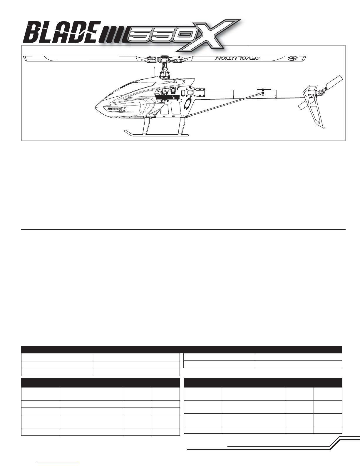
elcome to the world of Blade® Pro Series helicopter performance.
W
Over two decades of fl ying and design experience has gone into the
development of the Blade 550 X. Every part, down to the nuts and bolts,
has been chosen or designed with one goal in mind – giving you a nocompromise, 550-size 3D machine that is second to none.
Before you tear into the contents of this box, however, you must review
this manual. It’s been written and designed to make assembling the
Blade 550 X one of the most enjoyable, hassle-free building experiences
you’ll ever have. Every step is clearly illustrated and shows what parts
are needed to complete it. You’ll fi nd helpful building tips too.
Table of Contents
Tools Needed to Complete ..................................................................................4
Required Items ...................................................................................................4
Optional Items ....................................................................................................4
Assembly Guide ..................................................................................................4
Head Assembly (H) ..............................................................................................5
Frame Assembly (F) ............................................................................................7
Tail Assembly (T) ...............................................................................................10
Electronics Installation ......................................................................................13
Servo Arms and Links .......................................................................................15
Main Rotor Installation ......................................................................................15
Canopy Installation ...........................................................................................15
Programming Your Transmitter ..........................................................................16
Throttle Hold .....................................................................................................16
AR7200BX Setup ..............................................................................................17
AR7200BX Parameter Menu Tips ......................................................................17
Motor Direction Test ..........................................................................................17
If this is your fi rst helicopter building experience, there are a few things
you might want to get before you start unpacking parts. Many builders
prefer to lay out a towel or a rubber mat to prevent screws from bouncing off the worktable. It’s also a good idea to use small containers to
keep parts organized after you take them out of the bags.
Most importantly, take your time. Review every assembly step and make
sure you understand how the parts fi t before you start bolting things together. When you’re done, you’ll have a capable, smooth-fl ying helicopter
that fl ies exactly as it was designed to.
Control Test.......................................................................................................18
Low Voltage Cutoff ............................................................................................20
Flight Guidelines and Warnings .........................................................................20
Flying Your 550X ...............................................................................................20
Blade Tracking ..................................................................................................21
Adjusting the Rudder Gain.................................................................................21
Post Flight Inspection and Maintenance Checklist .............................................21
AR7200BX Fine-Tuning and Adjustment ............................................................21
Troubleshooting Guide ......................................................................................22
Limited Warranty ..............................................................................................23
Customer Service Information ...........................................................................24
Compliance Information for the European Union ................................................25
Exploded Views ......................................................................................... 98-100
Parts List / Ersatzteile / Pièces de rechange / Pezzi di ricambio ...............101-103
Optional Parts / Optionale Bauteile / Pièces optionnelles / Pezzi opzionali ...........103
Length
Height
Main Rotor Diameter
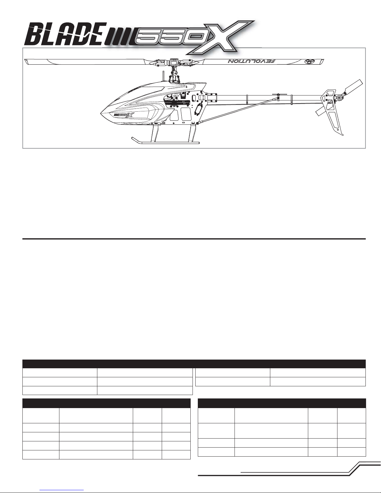
Component Kit Combo
Motor
ESC
BEC
Battery
Charger
Heli 550 Brushless Outrunner
Motor, 1360Kv
130 Amp Brushless ESC included included
10 Amp BEC included included
6S 22.2V 5000mAh 30C + Li-Po required required
DC Li-Po Balancing Charger required required
44.5 in (1130mm)
10.8 in (275mm)
49 in (1245mm)
Blade 550 X Specifi cations
included included
Tail Rotor Diameter
Flying Weight
Component Kit Combo
Transmitter
Receiver
Swash Servos
Tail Servo
To register your product online, visit www.bladehelis.com
DSM2®/DSMX® compatible
transmitter
AR7200BX 7CH DSMX
Flybarless Control System
Spektrum™ H6040 required included
Spektrum H6080G required included
7.4 –7.7 lb (3350 –3500 g)
3
9.45 in (240mm)
required required
required included
EN
Page 4
Tools Needed To Complete
• 1.5mm, 2mm, 2.5mm, and 3mm hex drivers
• Ball link pliers
• Needle nose pliers
• Phillips screwdriver
• Wire cutter
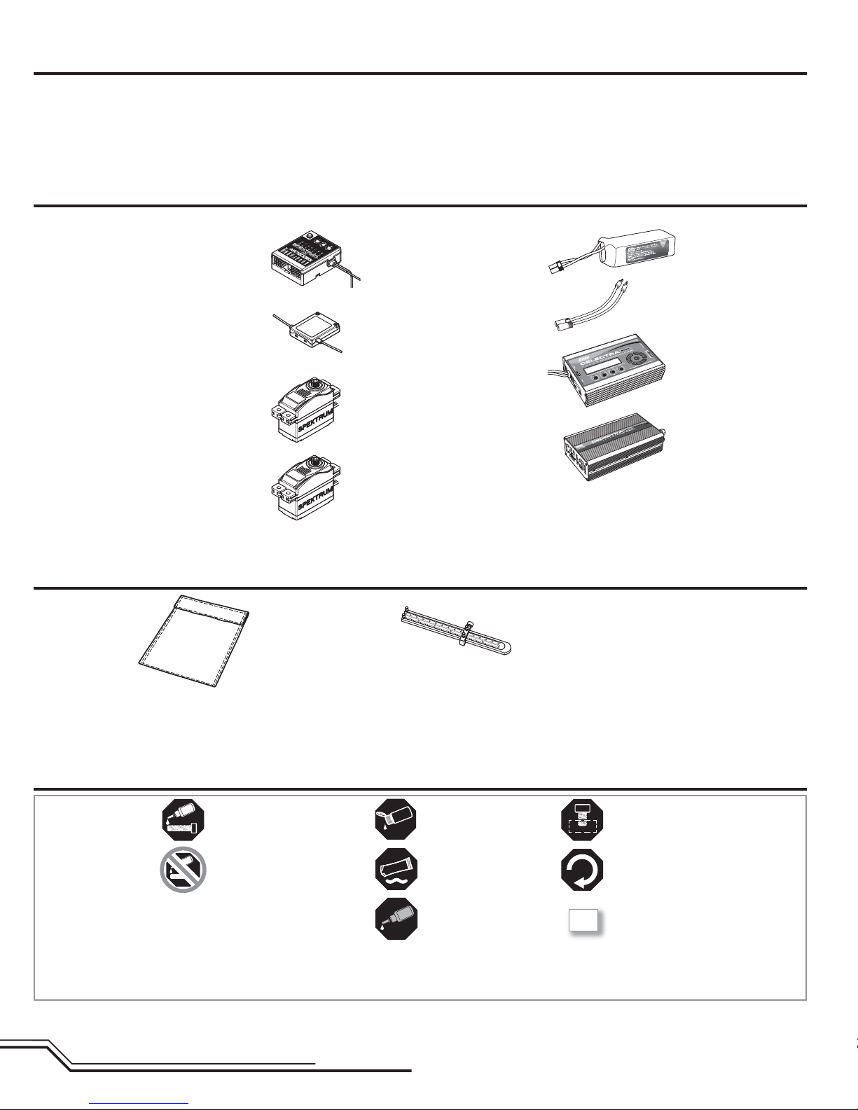
Required Items
• Pitch gauge
• Metric calipers
• Petroleum based, light viscosity lube
• Medium cyanoacrolate (CA)
• Receiver/Flybarless control unit
AR7200BX (SPMAR7200BX)
included with combo BLH5525C
• DSMX Remote Receiver (SPM9645)
included with combo BLH5525C
• 3 Servos
(3) H6040 servos (SPMSH6040)
included with combo BLH5525C
• 1 Tail servo
(1) H6080G servo (SPMSH6080G)
included with combo BLH5525C
Optional Items
• Dynamite
Protection Bag, Large
(DYN1405)
®
Li-Po Charge
• 5000mAh 6S 22.2V 30C LiPo,
10AWG with EC5™ connector
(EFLB50006S30)
®
• E-fl ite
• E-fl ite 200W charger (EFLC3020)
• Celectra™ 15VDC 250W
• DSM2
• Control Rod Set Up Tool
(RVO1004)
EC5 Device Charge
Lead with 6” Wire & Jacks,
12 AWG and EC5 connector
(EFLAEC512)
Power Supply (EFLC4010)
®
/DSMX® compatible DX6i 6 channel
transmitter or higher
Assembly Guide Legend
Apply BLUE Threadlock
Apply NO Threadlock
EN
Apply Petroleum based,
light viscosity lube
OIL
Apply Synthetic Grease
Apply MEDIUM CA
4
Loosely Tighten
Fully Tighten
Repeat Multiple Times
2X
Page 5

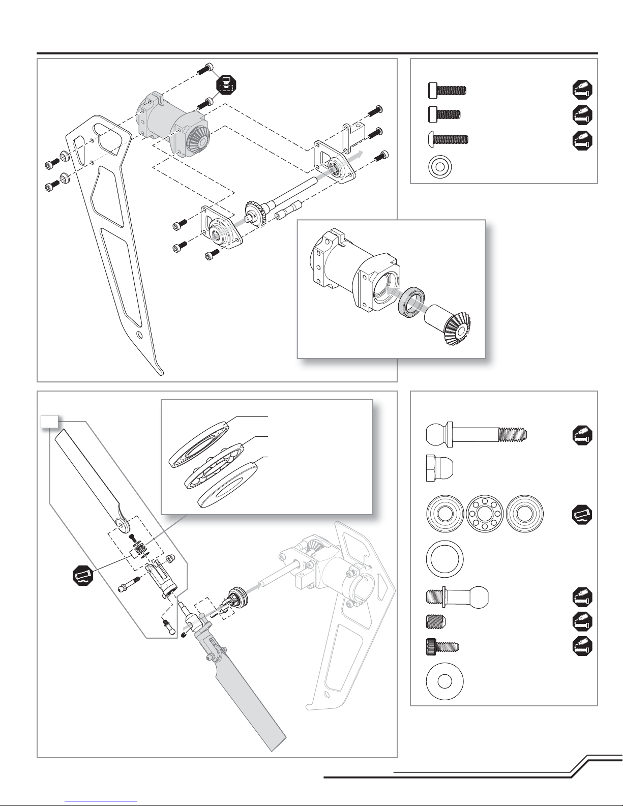
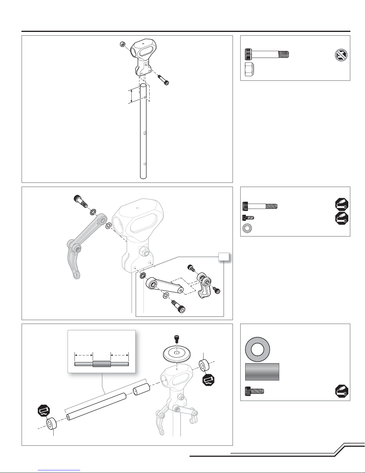
Head Assembly (H)
Step H1
Step H2
Step H1 parts (bags H1 and H2)
M4 X 22 cap head
shoulder bolt
M4 locknut
22mm
Step H2 parts (bag H1)
M3 X 18 cap head
shoulder bolt (x2)
M2 X 5 cap head bolt (x4)
Center sleeve
on the spindle
Damper
2X
Step washer (x4)
• The stepped sides of the washers should face the
radial bearings.
• Do not over-tighten. The follower arms should move
freely.
Step H3 parts (bags H1 and H2)Step H3
Damper (x2)
Spindle sleeve
M3 X 8 cap head bolt
Damper
• Clean the threads in the spindle thoroughly with
alcohol before installation.
5
EN
Page 6
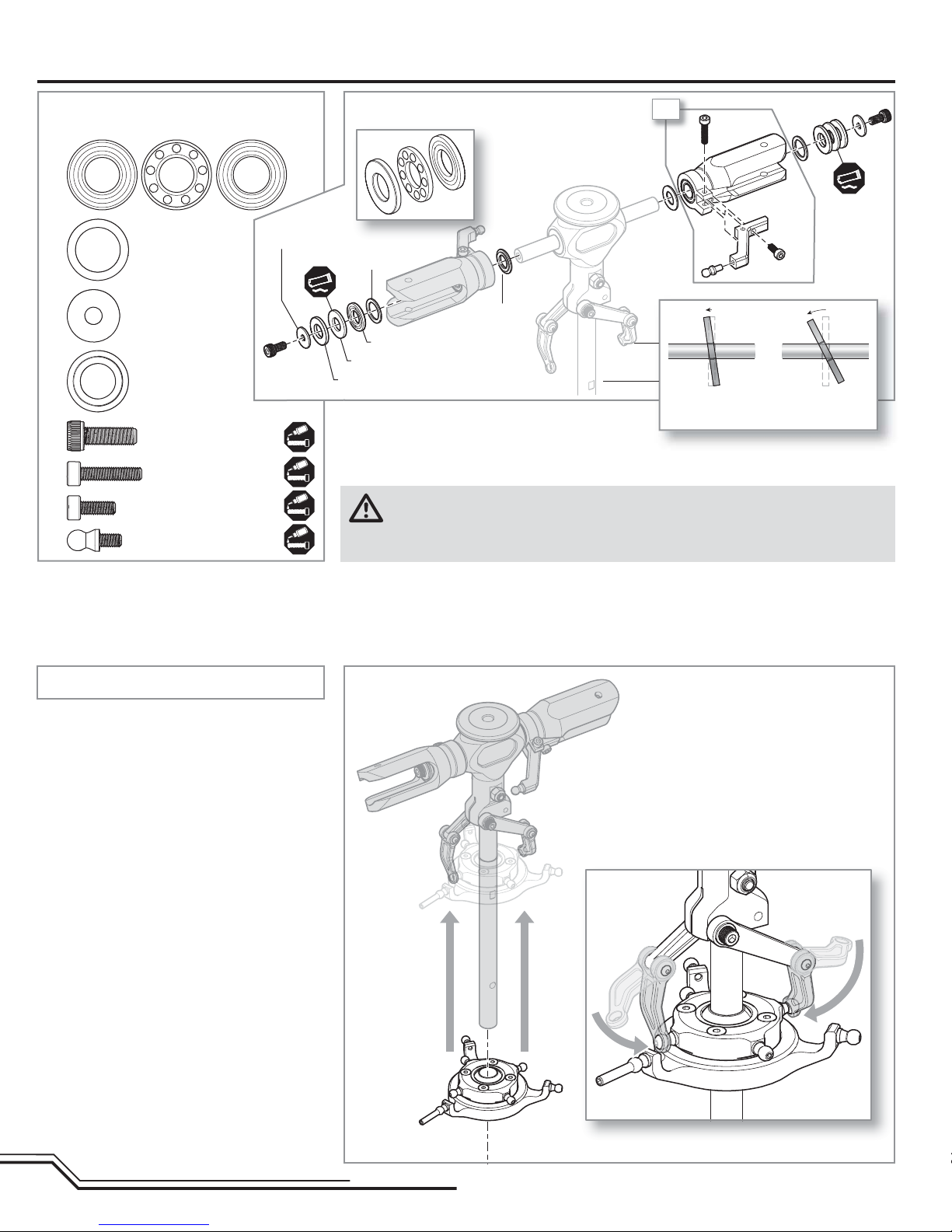
Head Assembly cont’d
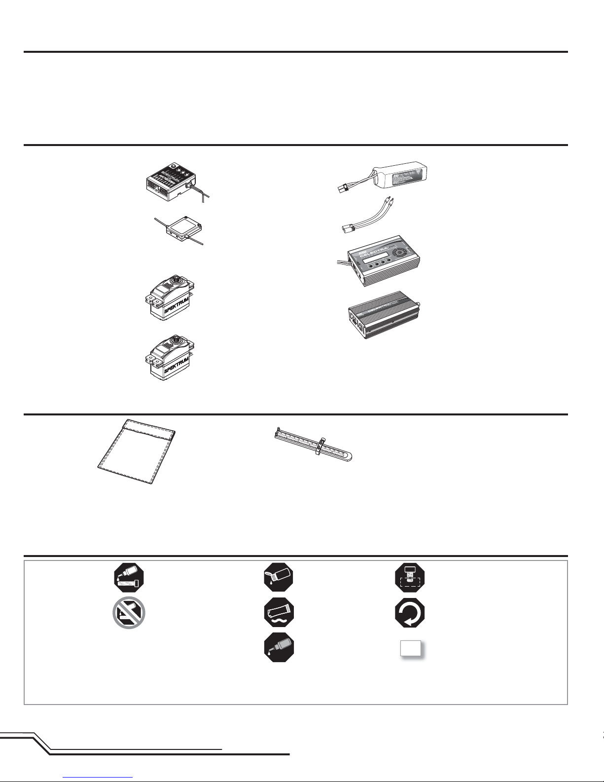
Step H4 parts (bag H3)
Thrust bearing (x2)
Thrust washer
10 X 14 X .8 (x2)
Spindle bolt washer
4 X 12 X 1 (x2)
Step washer (x2)
A
B
C
M4 X 12 bolt (x2)
M3 X 14 bolt (x2)
M3 X 8 bolt (x2)
Control ball (x2)
Spindle bolt washer
Thrust washer
A
Smaller I.D. thrust washer race
medium-strength threadlock to the bolts and allow time for the threadlock (about 4 to 6 hours) to dry
before attempting to fl y your helicopter.
Step H4
Step washer
Larger I.D. thrust washer race
Bearing cage
WARNING: Any time you loosen the spindle bolts, completely clean the bolts with denatured
alcohol making sure you have removed any residual oil. When putting bolts back on, apply
2X
B
Smaller inner
diameter (I.D.)
A
C
Larger inner
diameter (I.D.)
• Loosely install bolts B and C before tightening.
• The stepped washer faces the radial bearing in the
blade grip.
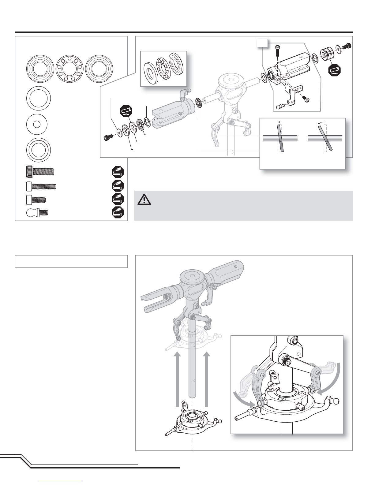
Step H5 parts (bag H4)
Step H5
EN
6
Page 7
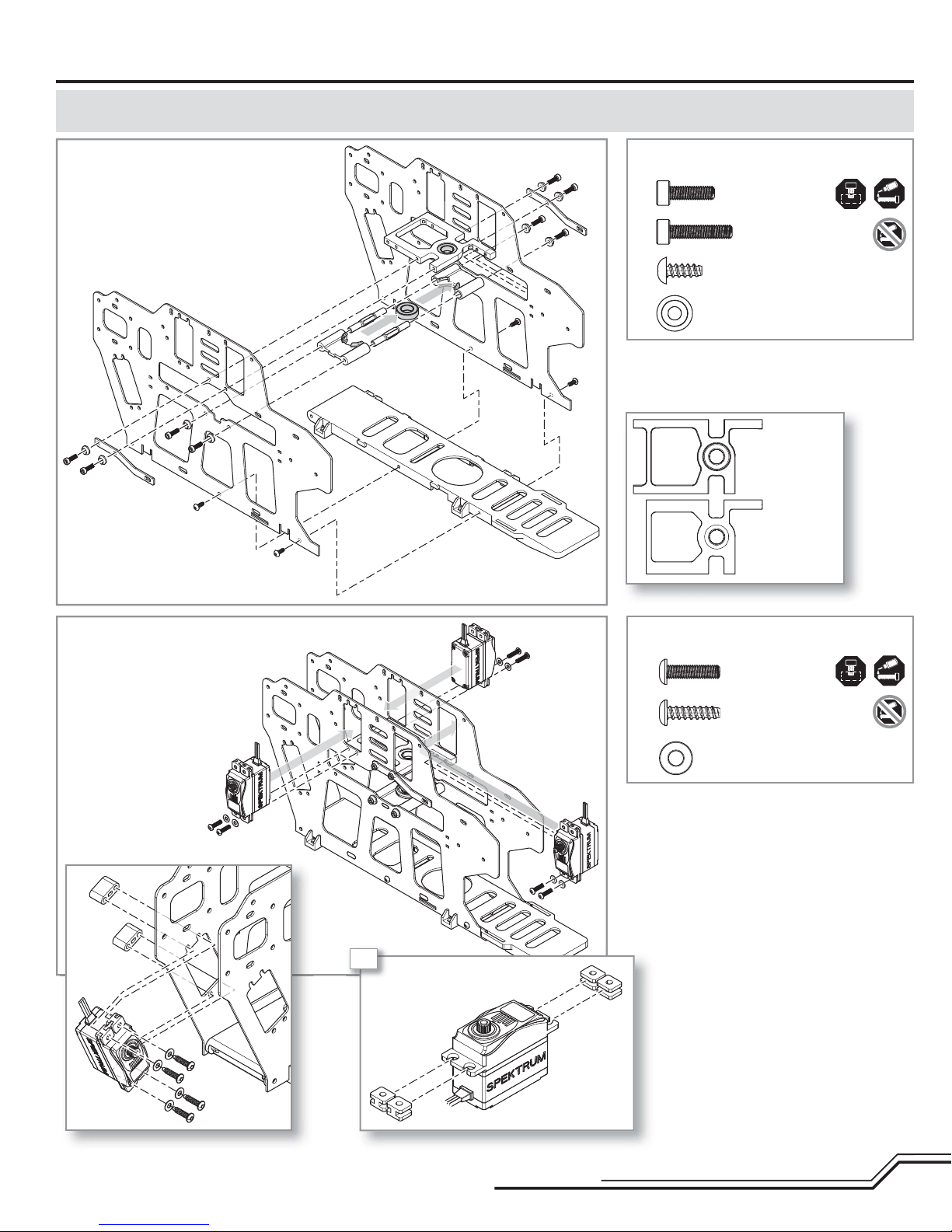
Frame Assembly (F)
ASSEMBLY NOTE: Before assembly, plan your wire routing for the servos. At any point where the servo wire is going to pass through or cross the frame plates,
use sandpaper to round the edge of the frame plate to prevent the wire from chafi ng.
Step F1
A
Step F1 parts (bags F1, F2, and F3)
A
A
B
C
C
B
C
C
B
C
• At this stage of the assembly, do not tighten
the bearing blocks or bottom plate screws.
Cap head bolt
M3 X 10 (x4)
Cap head bolt
M3 X 14 (x4)
Self tapping screw
M3 X 8 (x4)
M3 recessed washer (x8)
Top block
Middle block
Step F2
A
A
A
Step F2 parts (bag F5)
A
B
Button head screw
M3 X 12 (x6)
Self tapping screw
M3 X 12 (x4)
Servo washers (x10)
4X
B
B
7
EN
Page 8
Frame Assembly cont’d
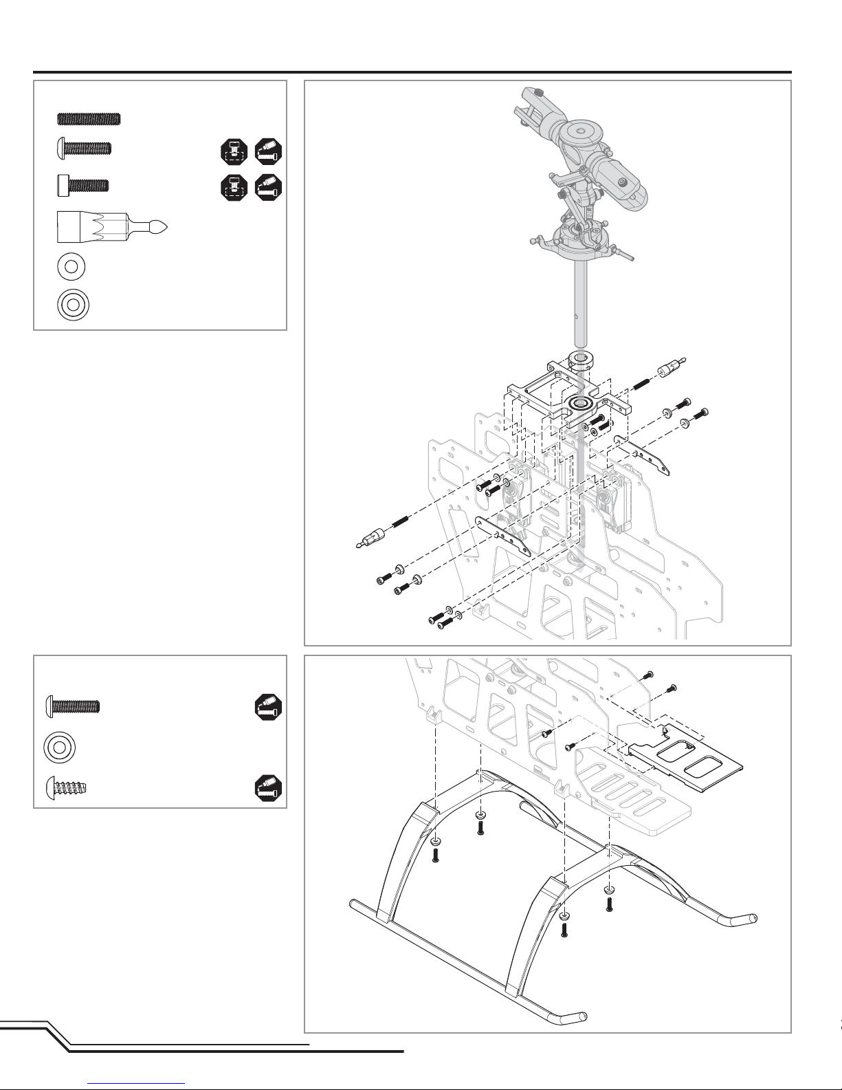
Step F3 parts (bags F3 and F5)
Setscrew
M3 X 11 (x2)
A
B
• Slide the mainshaft into position, then tighten all the
frame and servo screws.
Button head screw
M3 X 12 (x6)
Cap head bolt
M3 X 10 (x4)
Canopy
mounting post (x2)
M3 Washer (x6)
M3 Recessed
washer (x4)
Step F3
B
A
Step F4 parts (bag F3)
Button head screw
M3 X 12 (x4)
M3 Recessed washer (x6)
Self tapping screw
M3 X 8 (x4)
A
B
A
Step F4
EN
8
Page 9
Frame Assembly cont’d
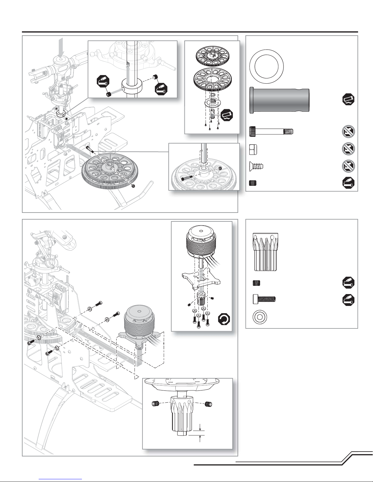
Step F5
Step F5 parts (bag M1)
Washer (x1)
One way sleeve (x1)
Shoulder cap head bolt
M4 X 22
M4 Lock nut
Counter sunk self tapping
screw M3 X 8 (x5)
Setscrew M3 X 4 (x2)
Step F6
Step F6 parts (bag F6)
6mm, 14 tooth pinion gear
Setscrew M3 X 4 (x2)
Cap head bolt M3 X 10 (x8)
M3 Recessed washer (x8)
3mm
9
EN
Page 10
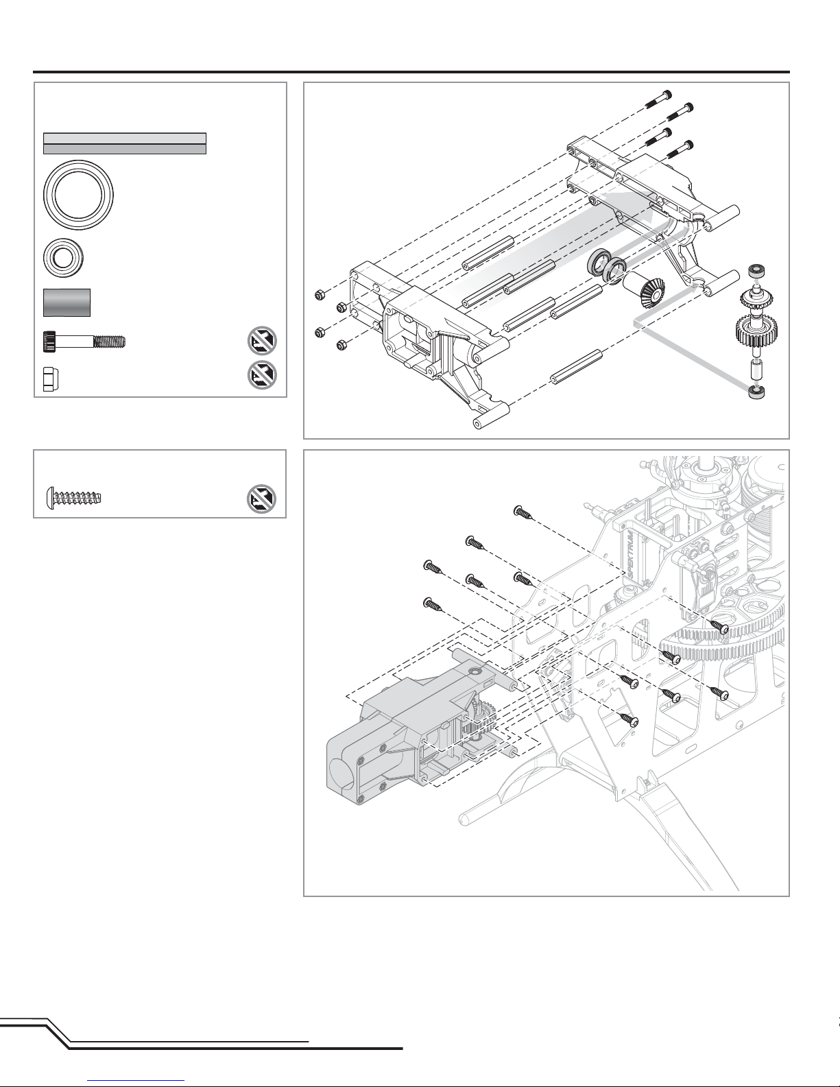
Tail Assembly (T)
Hexagonal posts (x6)
Radial bearing
12 X 18 X 4 (x2)
Radial bearing
5 X 10 X 4 (x2)
Brass spacer
Cap head shoulder
bolt M3 X 18 (x4)
M3 Lock nut (x4)
Step T1Step T1 parts (bag T1)
Step T2 parts (bag T1) Step T2
Button head self tapping
screw M3 X 16 (x12)
EN
10
Page 11
Tail Assembly cont’d
Step T3
B
Step T3 parts (bags T2 and T3)
A
C
B
B
B
A
B
C
Cap head bolt M3 X 10 (x2)
Cap head bolt M3 X 8 (x4)
Button head screw
M3 x 10 (x2 )
M3 Recessed washer (x2)
Step T4
2X
Step T4 parts (bags T4 and T5)
Small inner diameter race
Bearing cage
Large inner diameter race
B
A
A
B
Tail blade bolt (x2)
Tail blade nut (x2)
Thrust bearing (x2)
Thrust washer (x2)
Control ball (x2)
M4 x 3 Set screw
M3 X 8 Cap head
bolt (x2)
M3 Washer (x2)
11
EN
Page 12
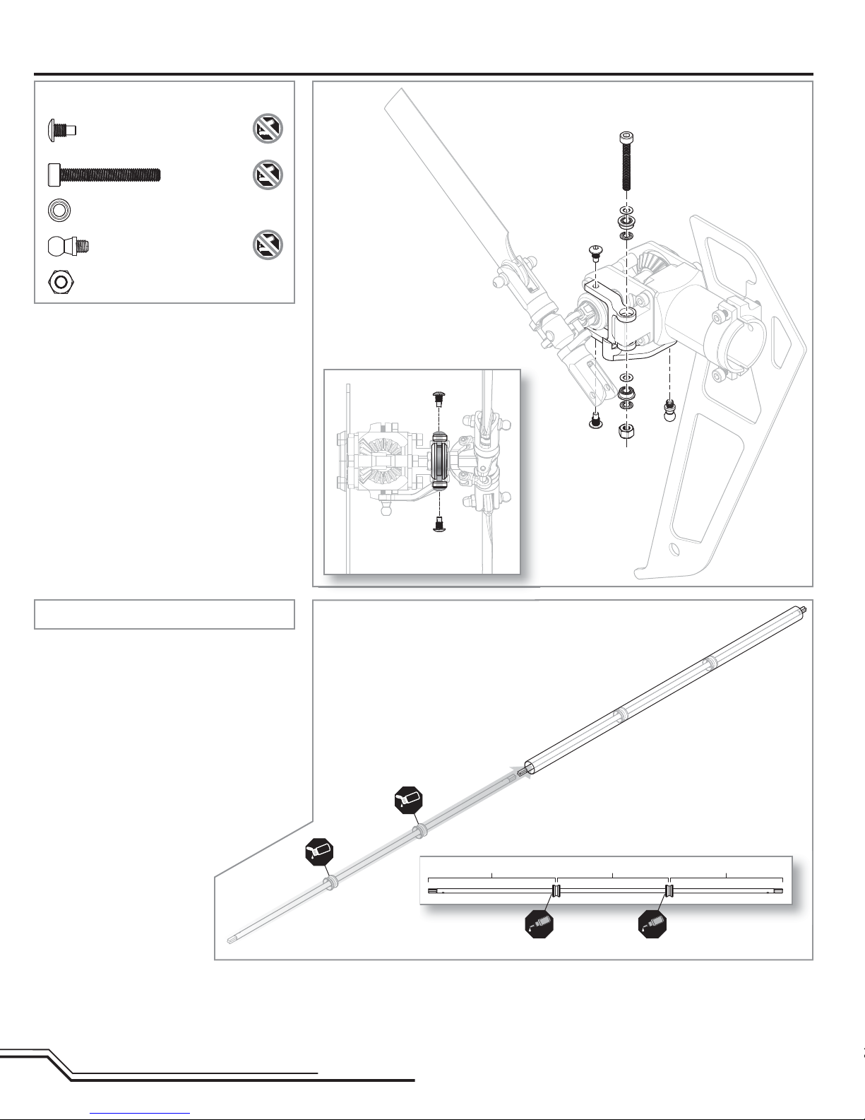
Tail Assembly cont’d
Button head screw
M3 X 5 (x2)
Cap head bolt M3 X 25
M3 Step washer (x4)
Control ball
M3 Lock nut
• The stepped side of the washer faces the radial
bearing.
Step T5Step T5 parts (bag T6)
Tail rotor blade
removed for clarity
Step T6a parts (bag T7)
• Glue the torque tube bearings in place by placing a
thin bead of CA on the torque tube at the given locations (200mm, 200mm), then slide the bearings onto
the CA. Do not allow CA to get into the bearings.
• Use oil on the outside of the torque tube bearing
holders to ease installation into the boom.
Step T6a
OIL
viewed from back
OIL
214 mm 200 mm 200 mm
EN
12
Page 13
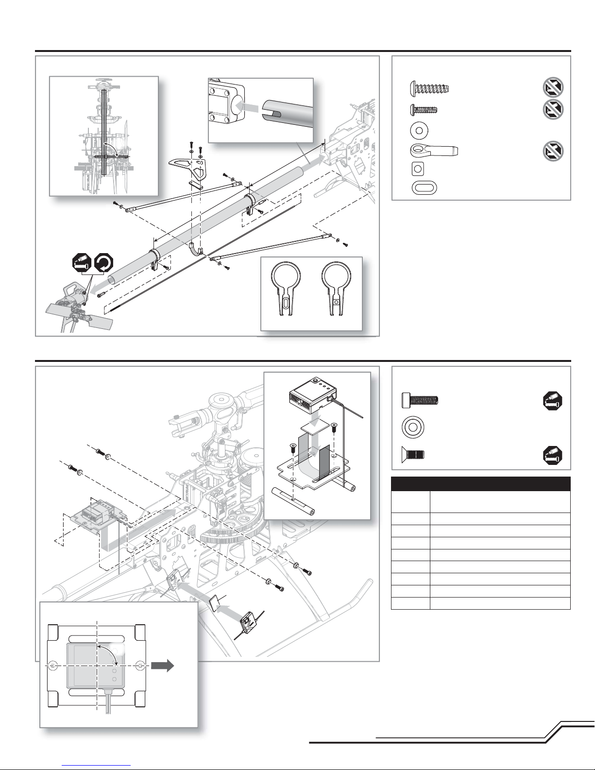
Tail Assembly cont’d
Step T6b Step T6b parts (bags T8 and T3)
viewed
from back
90°
A
B
Electronics Installation (E)
230 mm
B
viewed from left
A
A
A
B
120 mm
A
B
A
Front Rear
Self tapping screw
M3 X 12 (x4)
Self tapping screw
M2.5 X 8 (x2)
M3 Recessed washer (x6)
Ball link (x2)
Rear pushrod guide insert
Front pushrod guide insert
Flybarless Control Unit and Remote Receiver
Double-sided
foam tape
AR7200BX Alignment
90°
Step E1 parts (bag E1)
Cap head
M3 X 10 (x4)
Recessed washer (x4)
Counter sunk screw
M3 X 8 (x2)
AR7200BX servo connections
BIND/DAT Bind plug, telemetry module or data
logger (optional)
AUX2 BEC
AUX3 BEC
THRO Speed control
Rx L Remote receiver
ELEV Center swashplate servo
AILE Left swashplate servo
AUX1 Right swashplate servo
RUDD Tail servo
TIP: Connect the remote receiver before plugging in the
servo leads.
Front
viewed from top
13
EN
Page 14
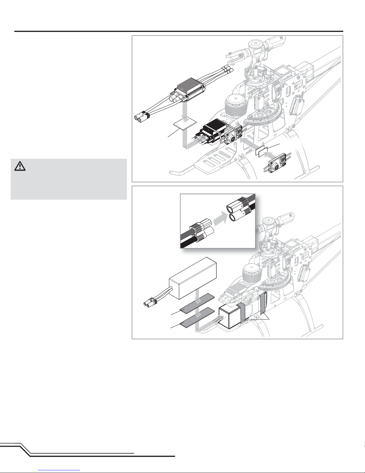
Electronics Installation cont’d
AR7200BX Arming
1. Lower the throttle.
2. Power on the transmitter.
3. Center the throttle trim.
4. Turn throttle hold ON.
5. Attach hook material to the helicopter frame and
loop material to the battery.
6. Install the fl ight battery on the helicopter frame.
Secure the fl ight battery with a hook and loop
strap.
7. Connect the battery cable to the ESC.
8. Do not move the helicopter until the AR7200BX
initializes. The swashplate will move up and down,
indicating that the unit is ready. The AR7200BX will
also emit a solid BLUE Status LED when it is ready
9. The helicopter motor will emit a series of tones,
indicating the ESC is armed.
CAUTION: Always disconnect the Li-Po battery
from the aircraft receiver when not in use to
avoid over-discharging the battery. Batteries discharged to a voltage lower than the lowest approved
voltage may become damaged, resulting in loss of performance and potential fi re when batteries are charged.
Speed control and BEC
Double-sided foam tape
Flight battery
Hook and loop
material
EN
Loop material
Hook material
Hook and loop
strap
14
Page 15
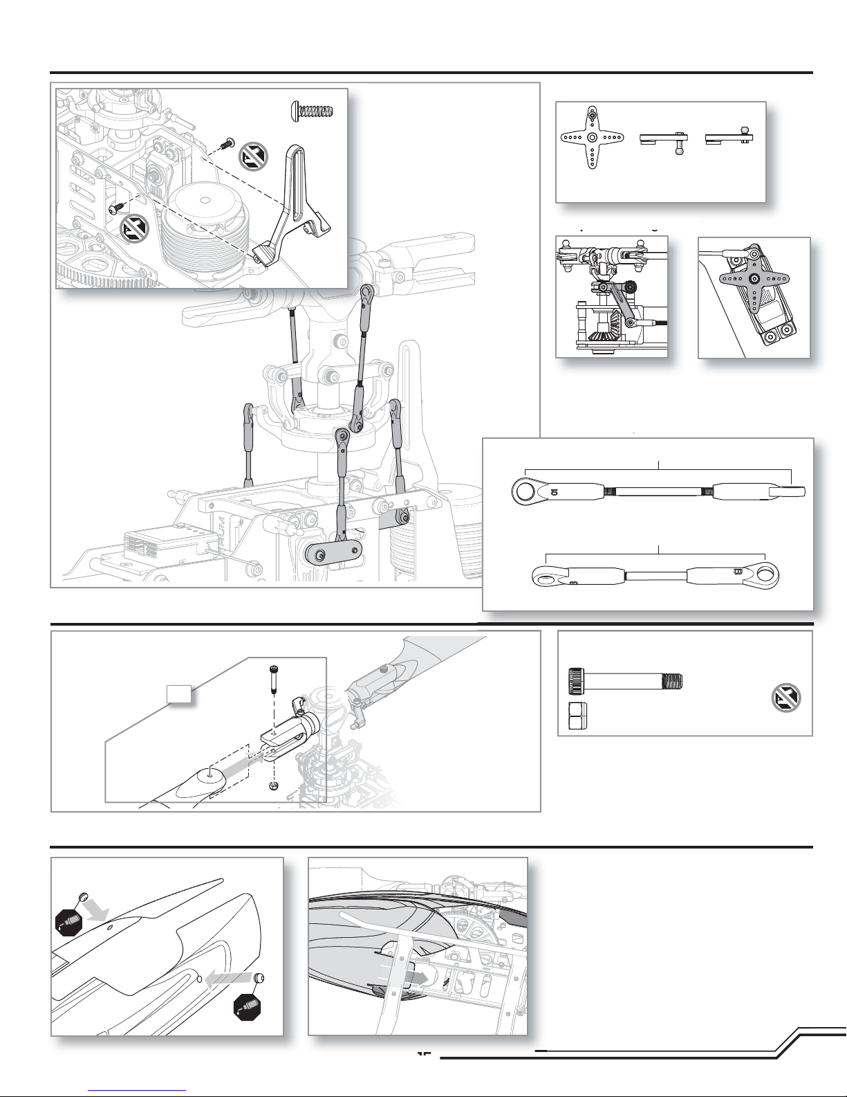
Servo Arms and Links Installation
pg
g
Self tapping screw
M3 X 8 (x2)
B
Servo ball link placement
Tail servo Rear swash
servos (x2)
Front swash
servo
Tail pushrod alignment
A
A
Tail pitch bellcrank
neutral position
(viewed from the bottom)
Tail servo arm
neutral position
(viewed from the right side)
Pushrod lengths
B
68mm
Main Rotor Installation
Main Rotor Blades
2X
Canopy Installation
Canopy Grommets
A
B
B
Swash to blade grip link, 68mm (x2)
56mm
Servo to swash link, 56mm (x3)
Main Rotor Blade parts
Main blade shoulder bolt M4 X 30 (x2)
M4 Lock nut (x2)
• The rotor blades should be tight enough to hold their
position if you hold the helicopter sideways, but loose
enough to swing freely if you move the helicopter
and stop abruptly.
15
EN
Page 16

Programming Your Transmitter
Program your transmitter before attempting to bind or fl y the helicopter. Transmitter programming values are shown below for the Spektrum DX6i, DX7/DX7se,
DX7s, DX8, and DX18. The fi les for models using SpektrumTM transmitters with AirWare™ software are also available for download online in the Spektrum Community.
DX6i
SETUP LIST
Model Type
HELI
Reverse
THRO N
AILE R
ELEV R
RUDD N
GYRO N
PITC R
Swash Type
1 Servo 90
Timer
4:00
DX7s/DX8/DX18
SYSTEM SETUP
Model Type
HELI
Swash Type
1 Servo Normal
F-Mode Setup
Flight Mode: F Mode
Hold: Hold
Frame Rate
11ms
DSMX
ADJUST LIST
D/R & Expo
0-AILE 100% 30%
0-ELEV 100% 30%
0-RUDD 100% INH
1-AILE 85% 30%
1-ELEV 85% 30%
1-RUDD 85% INH
Thro Curve
NORM 0% 40% 80% 80% 100%
STUNT 100% 100% 100% 100% 100%
HOLD 10% 10% 10% 10% 10%
Pitc Curve
NORM 30% 40% 50% 75% 100%
STUNT 0% 25% 50% 75% 100%
HOLD 0% 25% 50% 75% 100%
Travel Adj
THRO 100%
AILE 100%
ELEV 100%
RUDD 100%
GYRO 100%
PITC 100%
FUNCTION LIST
D/R & Expo
0-AILE 100% 30%
0-ELEV 100% 30%
0-RUDD 100% 0%
1-AILE 85% 30%
1-ELEV 85% 30%
1-RUDD 85% 0%
2-AILE 85% 30%
2-ELEV 85% 30%
2-RUDD 85% 0%
SERVO SETUP
Travel
THRO 100%
AILE 100%
ELEV 100%
RUDD 100%
GEAR 100%
PIT. 100%
Gyro
Rate SW-F. Mode
NORM 84%
STUNT 84%
Throttle Curve
NORM 0% 40% 60% 80% 100%
ST-1 80% 80% 80% 80% 80%
ST-2 (DX8/18 only) 100% 100% 100% 100% 100%
HOLD 0% 0% 0% 0% 0%
Pitch Curve
NOR 30% 40% 50% 75% 100%
ST-1 0% 25% 50% 75% 100%
ST-2 (DX8/18 only) 0% 25% 50% 75% 100%
HOLD 0% 25% 50% 75% 100%
Reverse
THRO N
AILE R
ELEV R
RUDD N
GEAR N
PIT. N
Timer
MODE Countdown
TIME 4:00 Tone/Vibe
START Throttle Out
POS 25
DX7/DX7se
SYSTEM LIST
Model Type
HELI
Swash Type
1 Servo 90
Gyro
SW F Mode
CH Gear
NORMAL/POS 0 68%
STUNT 1/POS 1 68%
STUNT 2/POS 2 68%
HOLD 68%
FUNCTION MODE
D/R & EXP
0-AILE 100% 30%
0-ELEV 100% 30%
0-RUDD 100% INH
1-AILE 85% 30%
1-ELEV 85% 30%
1-RUDD 85% INH
Thro Curve
NORM 0% 40% 60% 80% 100%
ST-1 80% 80% 80% 80% 80%
ST-2 100% 100% 100% 100% 100%
HOLD 0% 0% 0% 0% 0%
Pitc Curve
NORM 30% INH 50% INH 100%
ST-1 0% INH 50% INH 100%
ST-2 0% INH 50% INH 100%
HOLD 0% INH 50% INH 100%
Travel Adj
THRO 100%
AILE 100%
ELEV 100%
RUDD 100%
GEAR 100%
PIT. 100%
Reversing SW
THRO N RUDD N
AILE R GEAR N
ELEV R PIT. N
Gyro SENS
AUTO F.MODE
STNT 84%
HOLD 84%
Timer
4:00
Throttle Hold
When you move the throttle hold switch to the ON position, the helicopter motor
turns off. You will still have control of the helicopter cyclic and rudder commands.
The blades spin if throttle hold is OFF. For safety, turn throttle hold ON any time
you need to touch the helicopter or check the direction controls.
EN
You should also turn throttle hold ON to minimize damage if the helicopter is out
of control or in danger of crashing.
See your transmitter manual for more information on programming throttle hold.
16
Page 17

AR7200BX Recommended Blade 550 X Setup
Firmware version 3.X.X
SETUP MENU Menu LED solid
Status-LED: OFF Purple Red Flashing Red Solid Blue Flashing Blue Solid
A Mounting orientation
B Swashplate servo - frequency User defi ned 50 Hz 65 Hz 120 Hz 165 Hz 200 Hz*
C Tail servo - center position pulse length User defi ned 960 μs 760 μs 1520 μs*
D Tail servo - frequency User defi ned 50 Hz 165 Hz 270* Hz 333 Hz 560 Hz
E Tail servo - rotor endpoints Tail stick - move to right endpoint and wait/left endpoint and wait
F Tail - sensor direction normal reversed*
G Swashplate - servo centering
H Swashplate - mixer User defi ned mechanical 90° 120°* 140° 140° (1=1)
I Swashplate - servo directions nor|rev|rev nor|nor|rev* nor|rev|nor nor|nor|nor
J Swashplate - cyclic pitch geometry Aileron stick – adjust 6° cyclic pitch on the roll axis (blades aligned with fuselage)
K Collective pitch range
L Swashplate - cyclic limit Move aileron, elevator and pitch sticks – adjust max limits with tail stick
M Swashplate - sensor directions rev | rev rev | nor nor | rev nor | nor*
N Pirouette optimization direction normal reversed*
Reference
position
Collective stick on max and min position and use tail stick to adjust desired pitch.
Stock settings provide +/- 14 degrees of collective pitch.
ELE center pos. AIL center pos. PIT center pos.
Refer to the Spektrum AR7200BX manual for specifi c details.
upright
(vertical)
fl at (horizontal)*
PARAMETER MENU Menu LED is fl ashing quickly
Status-LED:
A Swashplate -
cyclic center adjustment
B Control behavior User defi ned normal sport* pro extreme transmitter
C Swashplate - pitching up behavior
D Tail - HeadingLock gain User defi ned very low low medium* high very high
E Stick deadband User defi ned 12* 34 5
F Tail - torque precompensation IX) User defi ned off* low - nor high - nor low - rev high - rev
G Cyclic response
H Pitch boost User defi ned off* low medium high very high
OFF Purple Red Flashing Red Solid Blue Flashing Blue Solid
Aileron and elevator stick – reset with tail stick
User defi ned very low low medium* high very high
User defi ned normal*
slightly
increased*
increased high very high
AR7200BX Parameter Menu Tips
Refer to the Spektrum AR7200BX manual to fi ne tune the Blade 550 X to your
fl ying and control style via the AR7200BX parameter menu.
If you would like to change the control behavior of the fl ybarless system to a
pre-defi ned behavior in the AR7200BX, adjust parameter B (default behavior is
transmitter).
If you would like to have the cyclic behavior to feel more linear OR more like
a fl ybarred helicopter, increase the cyclic response by adjusting parameter G
(default is ‘normal’).
Refer to the Spektrum AR7200BX manual for specifi c details on each
parameter.
Motor Direction Test
Place the helicopter outdoors on a clean, fl at and level surface (concrete or
asphalt) free of obstructions. Always stay clear of moving rotor blades.
1. Power on the transmitter. Make sure TH HOLD is ON and the fl ight mode
switch is in the normal position.
WARNING: The motor will spin when throttle is increased
and TH HOLD is OFF.
2. Lower the throttle completely.
WARNING: Stay at least 45 feet (13 meters) away from
the helicopter when the motor is running.
3. Connect the Li-Po battery to the ESC.
4. Turn TH HOLD OFF. Slowly increase the throttle until the drive train begins to
turn. The main blades spin clockwise when viewing the helicopter from the top.
The tail rotor blades spin counterclockwise when viewing the helicopter from
the right-hand side.
NOTICE: If the drive train does not turn with the motor or spins counterclockwise,
turn TH HOLD ON. Disconnect the battery from the helicopter and reverse any
two motor wire connections to the ESC and repeat the motor control test.
17
EN
Page 18
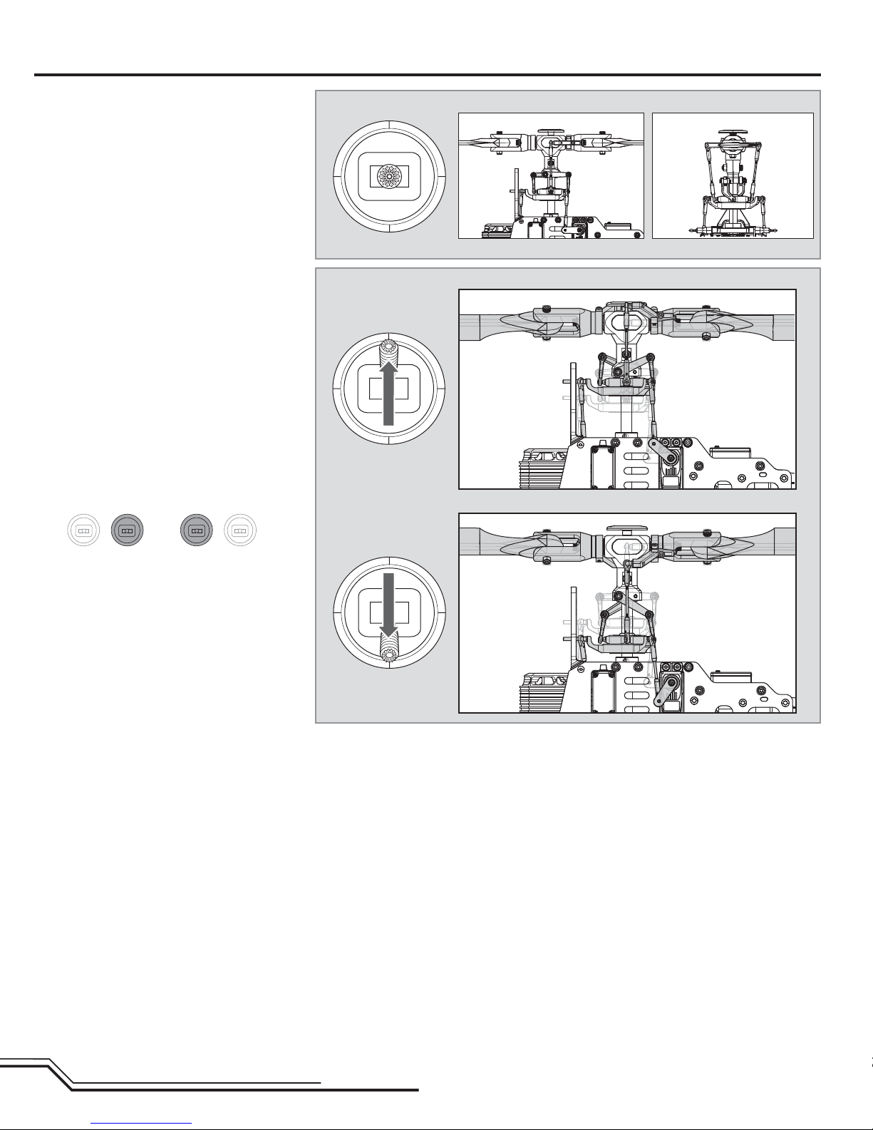
Control Tests
Swashplate set to 0° (Neutral)
Neutral (Viewed from left) Neutral (Viewed from back)
Positive pitch (Viewed from left)
Collective pitch
Mode 1
Mode 2
Negative pitch (Viewed from left)
EN
18
Page 19
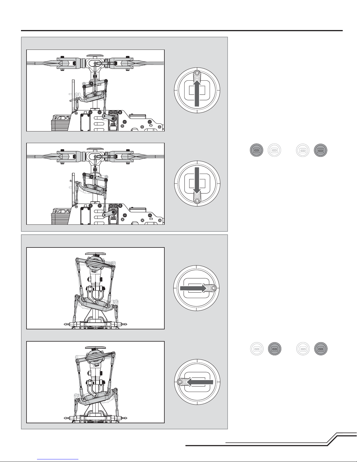
Forward elevator (Viewed from left)
Back elevator (Viewed from left)
Elevator
Mode 1
Mode 2
Right aileron (Viewed from back)
Left aileron (Viewed from back)
Aileron
Mode 1
Mode 2
19
EN
Page 20
Low Voltage Cuto (LVC)
Low voltage cutoff (LVC) protects the Li-Po battery from overdischarge in fl ight
and activates when the battery reaches 3V per cell under load.
Set your transmitter timer for 4 minutes and land when the timer expires.
Repeatedly activating LVC damages the fl ight battery and you will need to
replace the battery.
Flight Guidelines and Warnings
• Always keep aircraft in sight and under control.
• Always keep people and pets at least 45 feet (13 meters) away when the
battery is connected.
• Keep children out of the vicinity of this product at all times.
• Always turn on throttle hold at rotor strike.
• Always use fullly charged batteries.
• Always keep transmitter powered on while aircraft is powered.
• Always remove batteries before disassembly.
Flying Your 550X
Crash damage and battery damage are not covered under warranty.
Always disconnect and remove the Li-Po battery from the aircraft after each
fl ight. Charge your Li-Po battery to about half capacity before storage. During
storage, make sure battery charge does not fall below 3V per cell. A connected
battery will result in trickle discharge.
• Always keep moving parts clean.
• Always keep parts dry.
• Always let parts cool after use before touching.
• Always remove batteries after use.
• Always have a fi rst aid kit with you.
• Always have an appropriate fi re extinguisher with you.
• Never operate aircraft with damaged wiring.
• Never touch moving parts.
Consult local laws and ordinances before choosing a location
to fl y your aircraft.
Select a large, open area away from people and objects. Your fi rst fl ights should
be outdoors in low-wind conditions. Always stay at least 45 feet
(13 meters) away from the helicopter when it is fl ying.
Do not attempt to fl y the Blade 550 X indoors.
CAUTION: The Blade 550 X is intended for pilots with experience fl ying
aerobatic, collective pitch helicopters. The Blade 550 X is more responsive
than other Blade helicopters. If you are not an experienced 3D or collective pitch
helicopter pilot, do not attempt to fl y this product.
Takeoff
Gradually increase the throttle, allowing the rotors time to come up to speed.
CAUTION: Do not give any aileron, elevator or rudder commands before the
helicopter lifts off. Any control inputs prior to liftoff could cause a crash.
The helicopter will lift off the ground when the rotor head reaches a suitable
speed and you apply collective pitch. Once airborne, establish a low-level hover
to verify everything is functioning properly. DO NOT use trim to assist in holding
the Blade 550X in a desired position. The AR7200BX Flybarless Stabilization
System renders trim unnecessary by working to keep the helicopter in whatever
attitude you command with the control sticks.
Flying
This aircraft is extremely sensitive to control inputs. We recommend you fl y at
low rate settings for the fi rst few fl ights until you are familiar with its response.
For pilots new to collective pitch helicopters, familiarize yourself with your Blade
550 X in normal mode and at low rate.
CAUTION: Always fl y the helicopter with your back to the sun and wind to
prevent loss of fl ight control.
Landing
Establish a low level hover. Deliberately lower the throttle until the helicopter
lands. Make only small control corrections during this time to avoid rotor blade
strikes or other damage.
When the helicopter is in stunt mode:
• The rotor head speed is constant.
• The main rotor will increase negative pitch as the throttle/collective stick is
moved from the middle stick position to the low stick position. Negative pitch
allows the helicopter to fl y upside down and perform aerobatics.
Change between stunt and normal modes in a hover with the throttle near the
hovering stick position.
The helicopter may go up or down when you change between modes due to the
difference in the throttle and pitch curves.
NOTICE: To minimize damage, always activate throttle hold in preparation for or
during a crash.
WARNING: Only use Blade 550 X approved carbon fi ber main blades.
Do not use wooden main blades with the Blade 550 X. Using wooden
main blades may cause injury or property damage.
As you become more familiar with the helicopter’s response, adjust the rates,
expo, pitch and throttle curves to suit your fl ying style.
EN
20
Page 21
Blade Tracking
WARNING: Always maintain a safe distance of at least 15 meters
(45 feet) when checking the main rotor blade tracking.
To check the blade tracking:
1. Put the helicopter in a hover at an altitude near eye height.
Adjusting the Rudder Gyro Gain
• If the tail wags or oscillates, lower the gain on the gyro.
On your transmitter’s gyro menu, decrease the gyro gain values a small amount
at a time until the helicopter is stable within a particular fl ight mode
Post-Flight Inspection and Maintenance Checklist
√
Make sure the plastic ball link holds the control ball, but
Ball Links
Cleaning
Bearings
Wiring
Fasteners
is not tight (binding) on the ball. When a link is too loose
on the ball, it can separate from the ball during fl ight and
cause a crash. Replace worn ball links before they fail.
Make sure the battery is not connected before cleaning.
Remove dust and debris with a soft brush or a dry lint-free
cloth.
Replace bearings when they become notchy (sticky in
places when turning) or draggy.
Make sure wiring does not block moving parts. Replace
damaged wiring and loose connectors.
Make sure there are no loose screws, other fasteners or
connectors. Do not over tighten metal screws in plastic
parts. Tighten screw so parts are mated together, then turn
screw only 1/8th of a turn more.
2. Watch the movement at the blade tips. Both blades should travel in the
same plane.
3. If one blade tip appears to be higher than the other, land the helicopter,
disconnect the fl ight battery and adjust the blade linkages.
4. Repeat Steps 1 through 3 until both blades are moving in the same plane.
• If the tail is drifting while hovering, increase the gain on the gyro.
On your transmitter, increase the gyro gain values a small amount at a time until
the tail starts to wag/oscillate. Afterwards, reduce the gain until the tail stops
wagging/oscillating within a particular fl ight mode.
√
Make sure there is no damage to rotor blades and other
Rotors
Gyro
Gearing
parts which move at high speed. Damage to these parts
includes cracks, burrs, chips or scratches. Replace damaged parts before fl ying.
Make sure the AR7200BX is securely attached to the
frame. Replace the double-sided tape when necessary. The
helicopter will crash if the AR7200BX separates from the
helicopter frame.
Make sure gears are all in good condition. Watch for
chipped teeth or excessive wear. White dust around gears
is an indication of excess wear. Replace damaged gears
before fl ying.
AR7200BX Fine-tuning and Adjustment
Observed Behavior Suggested Adjustment
Cyclic response is too slow or too fast Adjust end points to fi t your fl ying style. Refer to your transmitter instruction
Control inputs feel delayed Increase Dial 2 on the AR7200BX
The helicopter seems to overshoot control input and then return Decrease Dial 2 on the AR7200BX
The helicopter tail stops too abruptly Decrease Dial 3 on the AR7200BX
The helicopter tail does not stop precisely Increase the rudder gain in your transmitter
manual for more information
Adjust the control behavior parameter in the AR7200BX to fi t your fl ying style.
Increase Dial 3 on the AR7200BX
Adjust the rudder heading lock gain parameter in the AR7200BX
21
EN
Page 22

Blade 550 X Troubleshooting Guide
Problem Possible Cause Solution
The helicopter was moved during initialization Lay the helicopter on its side during initialization if windy
AR7200BX will not initialize
LED on receiver fl ashes rapidly and
aircraft will not bind to transmitter
(during binding)
LED on receiver fl ashes rapidly and
aircraft will not respond to transmitter (after binding)
Helicopter will not respond to the
throttle but responds to other controls
Helicopter power is lacking
Helicopter will not lift off
The helicopter tail spins out of
control
The helicopter wobbles in fl ight
The transmitter is powered off Power on the transmitter
Controls are not centered
Transmitter is too near aircraft during binding process
Bind switch or button was not held while transmitter
was powered on
Aircraft or transmitter is too close to large metal object, wireless source or another transmitter
Less than a 5-second wait between fi rst powering on
transmitter and connecting fl ight battery to aircraft
Aircraft is bound to a different model memory
(ModelMatch
Flight battery/transmitter battery charge is too low Replace/recharge batteries
Transmitter may have been bound to a different model
(or with a different DSM Protocol)
Aircraft or transmitter is too close to large metal object, wireless source or another transmitter
Throttle not at idle and/or throttle trim is too high Lower the throttle stick and lower the throttle trim
The transmitter is not in normal mode or throttle hold
is on
The motor is not connected to the ESC or the motor
wires are damaged
Flight battery charge is too low Replace or recharge fl ight battery
Throttle channel is reversed Reverse the throttle channel on the transmitter
Flight battery has low voltage Fully charge the fl ight battery
Flight battery is old or damaged Replace the fl ight battery
Flight battery cells are unbalanced
Excessive current is being drawn through the BEC Check all servos and the helicopter motor for damage
Main rotor head is not spinning in the correct direc-
tion
Transmitter settings are not correct Check throttle and pitch curve settings and pitch control direction
Flight battery has low voltage Fully charge the fl ight battery
Main rotor blades are installed backwards
Rudder control and/or sensor direction reversed
Tail servo is damaged Check the rudder servo for damage and replace if necessary
Tail drive gears are damaged Replace damaged gears.
Inadequate control arm throw
Torque tube is not fully engaged in tail gears.
Cyclic gain is too high Decrease Dial 1 on the AR7200BX
Headspeed is too low
Dampers are worn Replace the main rotor head dampers
TM
radios only)
Center elevator, aileron and rudder controls. Make sure the throttle
is at idle
Power off transmitter, move transmitter a larger distance from aircraft, disconnect and reconnect fl ight battery to aircraft and follow
binding instructions
Power off transmitter and repeat bind process
Move aircraft and transmitter to another location and attempt binding
again
Leaving transmitter on, disconnect and reconnect fl ight battery to
aircraft
Select correct model memory on transmitter and disconnect and reconnect fl ight battery to aircraft
Select the right transmitter or bind to the new one
Move aircraft and transmitter to another location and attempt con-
necting again
Make sure the transmitter is in normal mode and throttle hold is off
Connect the motor wires to the ESC and check motor wires for damage
Fully charge the fl ight battery, allowing the charger time to balance
the cells
Make sure the main rotor head is spinning clockwise. Refer to the
motor control test
Install the main rotor blades with the thicker side as the leading
edge
Make sure the rudder control and the rudder sensor are operating in
the correct direction
Check the rudder control arm for adequate travel and adjust if necessary
Ensure the tail boom and tail gear box are fully seated. Confi rm tail
pushrod length and tail settings on AR7200BX are correct after making any changes.
Increase the helicopter's head speed via your transmitter settings
and/or using a freshly charged fl ight pack
EN
22
Page 23

Limited Warranty
What this Warranty Covers
Horizon Hobby, Inc. (“Horizon”) warrants to the original purchaser that the product
purchased (the “Product”) will be free from defects in materials and workmanship at
the date of purchase.
What is Not Covered
This warranty is not transferable and does not cover (i) cosmetic damage, (ii)
damage due to acts of God, accident, misuse, abuse, negligence, commercial use, or
due to improper use, installation, operation or maintenance, (iii) modifi cation of or to
any part of the Product, (iv) attempted service by anyone other than a Horizon Hobby
authorized service center, (v) Product not purchased from an authorized Horizon
dealer, or (vi) Product not compliant with applicable technical regulations.
OTHER THAN THE EXPRESS WARRANTY ABOVE, HORIZON MAKES NO OTHER
WARRANTY OR REPRESENTATION, AND HEREBY DISCLAIMS ANY AND ALL IMPLIED
WARRANTIES, INCLUDING, WITHOUT LIMITATION, THE IMPLIED WARRANTIES
OF NON-INFRINGEMENT, MERCHANTABILITY AND FITNESS FOR A PARTICULAR
PURPOSE. THE PURCHASER ACKNOWLEDGES THAT THEY ALONE HAVE
DETERMINED THAT THE PRODUCT WILL SUITABLY MEET THE REQUIREMENTS OF
THE PURCHASER’S INTENDED USE.
Purchaser’s Remedy
Horizon’s sole obligation and purchaser’s sole and exclusive remedy shall be that
Horizon will, at its option, either (i) service, or (ii) replace, any Product determined by
Horizon to be defective. Horizon reserves the right to inspect any and all Product(s)
involved in a warranty claim. Service or replacement decisions are at the sole
discretion of Horizon. Proof of purchase is required for all warranty claims. SERVICE
OR REPLACEMENT AS PROVIDED UNDER THIS WARRANTY IS THE PURCHASER’S
SOLE AND EXCLUSIVE REMEDY.
Limitation of Liability
HORIZON SHALL NOT BE LIABLE FOR SPECIAL, INDIRECT, INCIDENTAL OR
CONSEQUENTIAL DAMAGES, LOSS OF PROFITS OR PRODUCTION OR COMMERCIAL
LOSS IN ANY WAY, REGARDLESS OF WHETHER SUCH CLAIM IS BASED IN
CONTRACT, WARRANTY, TORT, NEGLIGENCE, STRICT LIABILITY OR ANY OTHER
THEORY OF LIABILITY, EVEN IF HORIZON HAS BEEN ADVISED OF THE POSSIBILITY
OF SUCH DAMAGES. Further, in no event shall the liability of Horizon exceed the
individual price of the Product on which liability is asserted. As Horizon has no
control over use, setup, fi nal assembly, modifi cation or misuse, no liability shall be
assumed nor accepted for any resulting damage or injury. By the act of use, setup or
assembly, the user accepts all resulting liability. If you as the purchaser or user are
not prepared to accept the liability associated with the use of the Product, purchaser
is advised to return the Product immediately in new and unused condition to the
place of purchase.
Law
These terms are governed by Illinois law (without regard to confl ict of law principals).
This warranty gives you specifi c legal rights, and you may also have other rights
which vary from state to state. Horizon reserves the right to change or modify this
warranty at any time without notice.
WARRANTY SERVICES
Questions, Assistance, and Services
Your local hobby store and/or place of purchase cannot provide warranty support
or service. Once assembly, setup or use of the Product has been started, you
must contact your local distributor or Horizon directly. This will enable Horizon
to better answer your questions and service you in the event that you may need
any assistance. For questions or assistance, please visit our website at www.
horizonhobby.com, submit a Product Support Inquiry, or call 877.504.0233 toll free
to speak to a Product Support representative.
Inspection or Services
If this Product needs to be inspected or serviced and is compliant in the country
you live and use the Product in, please use the Horizon Online Service Request
submission process found on our website or call Horizon to obtain a Return
Merchandise Authorization (RMA) number. Pack the Product securely using a
shipping carton. Please note that original boxes may be included, but are not
designed to withstand the rigors of shipping without additional protection. Ship via a
carrier that provides tracking and insurance for lost or damaged parcels, as Horizon
is not responsible for merchandise until it arrives and is accepted at our facility.
An Online Service Request is available at http://www.horizonhobby.com/content/_
service-center_render-service-center. If you do not have internet access, please
contact Horizon Product Support to obtain a RMA number along with instructions
for submitting your product for service. When calling Horizon, you will be asked to
provide your complete name, street address, email address and phone number
where you can be reached during business hours. When sending product into
Horizon, please include your RMA number, a list of the included items, and a brief
summary of the problem. A copy of your original sales receipt must be included for
warranty consideration. Be sure your name, address, and RMA number are clearly
written on the outside of the shipping carton.
NOTICE: Do not ship LiPo batteries to Horizon. If you have any issue with a
LiPo battery, please contact the appropriate Horizon Product Support offi ce.
Warranty Requirements
For Warranty consideration, you must include your original sales receipt
verifying the proof-of-purchase date. Provided warranty conditions have been
met, your Product will be serviced or replaced free of charge. Service or replacement
decisions are at the sole discretion of Horizon.
Non-Warranty Service
Should your service not be covered by warranty, service will be completed
and payment will be required without notifi cation or estimate of the
expense unless the expense exceeds 50% of the retail purchase cost. By
submitting the item for service you are agreeing to payment of the service without
notifi cation. Service estimates are available upon request. You must include this
request with your item submitted for service. Non-warranty service estimates will be
billed a minimum of ½ hour of labor. In addition you will be billed for return freight.
Horizon accepts money orders and cashier’s checks, as well as Visa, MasterCard,
American Express, and Discover cards. By submitting any item to Horizon for service,
you are agreeing to Horizon’s Terms and Conditions found on our website http://
www.horizonhobby.com/content/_service-center_render-service-center.
ATTENTION: Horizon service is limited to Product compliant in the country
of use and ownership. If received, a non-compliant Product will not be
serviced. Further, the sender will be responsible for arranging return
shipment of the un-serviced Product, through a carrier of the sender’s
choice and at the sender’s expense. Horizon will hold non-compliant
Product for a period of 60 days from notifi cation, after which it will be
discarded.
23
EN
Page 24

Warranty and Service Contact Information
Country of Purchase Horizon Hobby Address Phone Number/Email Address
Horizon Service Center
(Electronics and engines)
United States of America
Horizon Product Support (All other products)
United Kingdom Horizon Hobby Limited
Germany Horizon Technischer Service
France Horizon Hobby SAS
China Horizon Hobby – China
4105 Fieldstone Rd
Champaign, Illinois
61822 USA
4105 Fieldstone Rd
Champaign, Illinois
61822 USA
Units 1-4 Ployters Rd
Staple Tye
Harlow, Essex
CM18 7NS
United Kingdom
Christian-Junge-Straße 1
25337 Elmshorn
Germany
11 Rue Georges Charpak
77127 Lieusaint, France
Room 506, No. 97 Changshou Rd.
Shanghai, China 200060
877-504-0233
Online Repair Request:
visit www.horizonhobby.com/service
877-504-0233
productsupport@horizonhobby.com
+44 (0) 1279 641 097
sales@horizonhobby.co.uk
+49 (0) 4121 2655 100
service@horizonhobby.de
+33 (0) 1 60 18 34 90
infofrance@horizonhobby.com
+86 (021) 5180 9868
info@horizonhobby.com.cn
Customer Service Information
Country of Purchase Horizon Hobby Address Phone Number/Email Address
United States of America Sales
United Kingdom Horizon Hobby Limited
Germany Horizon Hobby GmbH
France Horizon Hobby SAS
China Horizon Hobby – China
4105 Fieldstone Rd
Champaign, Illinois
61822 USA
Units 1-4 Ployters Rd
Staple Tye
Harlow, Essex
CM18 7NS
United Kingdom
Christian-Junge-Straße 1
25337 Elmshorn
Germany
11 Rue Georges Charpak
77127 Lieusaint, France
Room 506, No. 97 Changshou Rd.
Shanghai, China 200060
(800) 338-4639
sales@horizonhobby.com
+44 (0) 1279 641 097
sales@horizonhobby.co.uk
+49 (0) 4121 2655 100
service@horizonhobby.de
+33 (0) 1 60 18 34 90
infofrance@horizonhobby.com
+86 (021) 5180 9868
info@horizonhobby.com.cn
EN
24
Page 25
Compliance Information for the European Union
Declaration of Conformity
(in accordance with ISO/IEC 17050-1)
No. HH2012101407
Product(s): BLH 550 X Pro Kit
Item Number(s): BLH5525
The object of declaration described above is in conformity with the requirements of the specifi cations
listed below, following the provisions of the European EMC Directive 2004/108/EC:
EN55022:2010 + AC:2011
EN55024:2010
Signed for and on behalf of:
Horizon Hobby, Inc.
Champaign, IL USA
Oct 14, 2012
Executive Vice President and Chief Operating Offi cer
International Operations and Risk Management
Steven A. Hall
Horizon Hobby, Inc.
Declaration of Conformity
(in accordance with ISO/IEC 17050-1)
No. HH2012122101
Product(s): Blade 550X Pro Combo
Item Number(s): BLH5525C
The object of declaration described above is in conformity with the requirements of the specifi cations
listed below, following the provisions of the European R&TTE directive 1999/5/EC and EMC Directive
2004/108/EC:
EN301 489-1 V1.7.1: 2006
EN301 489-17 V1.3.2: 2008
EN55022:2010 + AC:2011
EN55024:2010
Signed for and on behalf of:
Horizon Hobby, Inc.
Champaign, IL USA
Dec 21, 2012
Executive Vice President and Chief Operating Offi cer
International Operations and Risk Management
Steven A. Hall
Horizon Hobby, Inc.
Instructions for disposal of WEEE by users in the European Union
This product must not be disposed of with other waste. Instead, it is the user’s responsibility to dispose of their waste equipment by handing it over
to a designated collections point for the recycling of waste electrical and electronic equipment. The separate collection and recycling of your waste
equipment at the time of disposal will help to conserve natural resources and ensure that it is recycled in a manner that protects human health and the
environment. For more information about where you can drop off your waste equipment for recycling, please contact your local city offi ce, your household waste disposal service or where you purchased the product.
25
EN
Page 26
HINWEIS
Allen Anweisungen, Garantien und anderen zugehörigen Dokumenten sind Änderungen nach Ermessen von Horizon Hobby, Inc. vorbehalten. Aktuelle Produktliteratur fi nden Sie auf horizonhobby.com im Support-Abschnitt für das Produkt.
Spezielle Bedeutungen
Die folgende Begriffe werden in der gesamte Produktliteratur verwendet, um die Gefährdungsstufen im Umgang mit dem Produkt zu defi nieren:
Der Zweck der Sicherheitssymbole ist es Ihre Aufmerksamkeit auf mögliche Gefahren zu lenken. Die Symbole und ihre Erklärungen erfordern ihre sorgfältige Aufmerksamkeit und Verstehen. Die Symbole eliminieren nicht die Gefahr. Die Anweisungen und Warnungen ersetzen nicht angemessene und korrekte Unfallverhütungsmaßnahmen.
HINWEIS: Verfahren können bei nicht ordnungsgemäßer Durchführung womöglich Schäden an physischem Eigentum UND geringfügige oder keine Verletzungen verursachen.
ACHTUNG: Verfahren können bei nicht ordnungsgemäßer Durchführung womöglich Schäden an physischem Eigentum UND schwere Verletzungen verursachen.
WARNUNG: Verfahren können bei nicht ordnungsgemäßer Durchführung möglicherweise Schäden an Eigentum, Kollateralschäden UND schwere Verletzungen bis zum
Tot ODER höchstwahrscheinlich oberfl ächliche Verletzungen verursachen.
Sicherheitsalarm: Zeigt eine Warnung oder Vorsichtmaßregel an. Hier ist Aufmerksamkeit erforderlich um ernste Körperverletzungen zu vermeiden.
WARNUNG: Lesen Sie die GESAMTE Bedienungsanleitung, um sich vor Inbetriebnahme mit den Funktionen des Produkts vertraut zu machen. Eine nicht ordnungs-
gemäße Bedienung des Produkts kann das Produkts und persönliches Eigentum schädigen und schwere Verletzungen verursachen.
Dieses ist ein anspruchvolles Hobby Produkt für den fortgeschrittenen Hubschrauberpiloten mit Erfahrung von Pitchgesteuerten (CCPM) Hubschraubern ((Cyclic Collective
Pitch Mixing oder Collective Pitch Helicopter) wie zum Beispiel dem Blade SR oder dem Blade mCP X. Es muss mit Vorsicht und Umsicht bedient werden und erfordert
einige mechanische Grundfertigkeiten. Dies ist ein hoch entwickeltes Produkt für den Hobbygebrauch. Es muss mit Vorsicht und Umsicht bedient werden und erfordert
einige mechanische Grundfertigkeiten. Wird das Produkt nicht sicher und umsichtig verwendet, so könnten Verletzungen oder Schäden am Produkt oder anderem Eigentum
entstehen. Dieses Produkt ist nicht für den Gebrauch durch Kinder ohne direkte Aufsicht eines Erwachsenen vorgesehen. Versuchen Sie nicht, das Produkt ohne Zustimmung von Horizon Hobby, Inc. zu zerlegen, mit nicht-kompatiblen Komponenten zu verwenden oder beliebig zu verbessern. Dieses Handbuch enthält Sicherheitshinweise
sowie Anleitungen zu Betrieb und Wartung. Es ist unerlässlich, dass Sie alle Anleitungen und Warnungen in diesem Handbuch vor dem Zusammenbau, der Einrichtung oder
der Inbetriebnahme lesen und diese befolgen, um eine korrekte Bedienung zu gewährleisten und Schäden bzw. schwere Verletzungen zu vermeiden.
Alters Empfehlung: Nicht für Anfängerpiloten unter 14 Jahren. Das ist kein Spielzeug.
Zusätzliche Sicherheitsmaßnahmen und Warnungen
Dieses Modell wird über ein Funksignal gesteuert. Funksignale können von außerhalb gestört werden, ohne dass Sie darauf Einfl uss nehmen können. Dies kann zu einem
vorübergehenden Verlust der Steuerungskontrolle führen.
• Stellen Sie immer sicher, dass Sie vollständig die Kontrollen des Senders und Ihren Einfl uß auf die Bewegung des Hubschrauber verstanden haben.
• Betreiben Sie Ihr Modell stets auf offenen Geländen, weit ab von Automobilen, Verkehr und Menschen.
• Befolgen Sie die Anweisungen und Warnungen für dieses Produkt und jedwedes optionales Zubehörteil (Ladegeräte, wiederaufl adbare Akkus etc.) stets sorgfältig.
• Halten Sie sämtliche Chemikalien, Kleinteile und elektrische Komponente stets außer Reichweite von Kindern.
• Halten Sie dieses Produkt immer aus der Reichweite von Kindern.
• Halten Sie dieses Produkt stets ausser Reichweite von Kindern. Lagern Sie dieses Produkt immer ausserhalb der Reichweite von Kindern.
• Halten Sie stets ihr Haar über den Schultern gesichert, dass es sich nicht in den Blättern verfangen kann.
• Feuchtigkeit beschädigt die Elektronik. Vermeiden Sie den Wasserkontakt aller Komponenten, die dafür nicht speziell ausgelegt und entsprechend geschützt sind.
• Betreiben und warten Sie dieses Produkt immer bei Tageslicht.
• Stellen Sie vor dem Betrieb immer sicher dass alle Befestigungen gesichert sind.
• Lagern Sie dieses Produkt immer an einem sicheren trockenen Ort.
• Berühren Sie nicht den Motor, da er während des Betriebes extrem heiß werden kann.
• Fliegen Sie den Hubschrauber nicht Indoor (in Räumen, Gebäuden oder Hallen).
• Vertrauen Sie nicht ausschließlich auf die Sicherheitsmechanismen die im Sender und Empfänger eingebaut sind. Versichern Sie sich immer, dass Sie das Produkt und wie
es zu betreiben ist verstehen.
• Versichern Sie sich immer, dass Sie das Produkt und wie es zu betreiben ist verstehen.
• Verwenden Sie für dieses Produkt nur von Horizon zugelassene Teile und Zubehör.
• Nehmen Sie niemals ein Element des Modells in Ihren Mund, da dies zu schweren Verletzungen oder sogar zum Tod führen könnte.
• Betreiben Sie Ihr Modell niemals mit Senderbatterien.
• Schließen Sie kein Akku an wenn Sie das Produkt nicht testen oder in Betrieb nehmen.
• Betreiben Sie dieses Produkt nicht wenn Sie müde sind, sich unwohl fühlen, Medikamente nehmen die ihre Reaktionsfähigkeit beeinfl ussen, oder unter dem Einfl uß von
Drogen oder Alkohol stehen.
• Sprühen Sie niemals Glasreiniger oder andere Flüssigkeiten auf dieses Produkt.
• Bei der Wartung oder dem Betrieb des Produkt dürfen Sie keine hängende oder lose Gegenstände an ihrer Person haben.
HINWEIS:
Bei der Verwendung von Komponenten, die von Horizon nicht zugelassen sind, kann eine mögliche Serviceleistung abgelehnt werden.
WARNUNG: Das ist großer Hubschrauber mit Rotorblättern die mit hoher Drehzahl drehen. Seien Sie extrem aufmerksam und benutzen ihren gesunden
Menschenverstand wenn Sie dieses Produkt warten oder nutzen. Sollte Ihnen eine beliebige Funktion oder Vorgang der in dieser Anleitung beschrieben
wird nicht klar sein betreiben Sie das Produkt NICHT. Kontaktieren Sie den technischen Service von Horizon zur Unterstützung.
WARNUNG: Halten Sie mit dem Hubschrauber mindestens 13 Meter Abstand zu sich selbst und anderen.
DE
26
Page 27
®
illkommen in der Welt der Blade Pro Serie Helikopter Performance.
Über 20 Jahre Erfahrung in Flug und Konstruktion sind in die Ent-
W
wicklung des Blade 550X gefl ossen. Jedes Teil bis zur kleinsten Mutter
wurde nur mit einem Ziel entwickelt oder ausgewählt, um Ihnen damit
einen unvergleichlichen 550 3D Hubschrauber anbieten zu können.
Bevor Sie sich sich auf den Boxinhalt stürzen ist es allerdings notwendig,
dass Sie bitte diese Bedienungsanleitung lesen. Die wurde geschrieben
damit Ihnen die Montage des Hubschraubers Freude macht und zu
einem der besten Bauprojekte wird, die Sie jemals durchgeführt haben.
Jeder Schritt ist klar abgebildet und zeigt Ihnen welche Teile zur Montage
benötigt werden. Sie fi nden in der Anleitung auch hilfreiche Bautipps.
Inhaltsverzeichnis
Benötigtes Werkzeug .......................................................................................28
Erforderliche Teile ............................................................................................ 28
Optionales Zubehör ..........................................................................................28
Erklärung der Montagesymbole .......................................................................28
Rotorkopfmontage (H) ...................................................................................... 29
Chassismontage (F) .........................................................................................31
Heckmontage (T) .............................................................................................34
Einbau der Elektronik ....................................................................................... 37
Servoarm und Anlenkungen ............................................................................. 39
Montage Hauptrotorkopf ..................................................................................39
Montage der Kabinenhaube .............................................................................39
Programmieren des Senders ............................................................................40
Throttle Hold (Gas aus) .................................................................................... 40
AR7200 Standard Blade 550 X Setup ............................................................... 41
Tipps zum AR7200BX-Parametermenü ............................................................41
Test der Motorsteuerung .................................................................................. 42
Sollte dieses ihr erstes Hubschrauberprojekt sein, gibt es noch ein paar
Dinge die Sie benötigen bevor Sie mit dem Auspacken beginnen. Viele
Modellbauer nutzen ein Handtuch oder eine Gummimatte als Unterlage
auf dem Arbeitstisch, damit keine Schrauben herunterfallen. Kleine Kästchen sind für Organisation und Aufbewahrung der Teile nützlich wenn
Sie aus der Packung genommen wurden.
Eines der wichtigsten Dinge ist es aber sich Zeit zu nehmen und sicher
zu stellen, dass Sie verstehen wie die Teile montiert werden. Haben Sie
das gemeistert fl iegt ihr Hubschrauber genauso präzise wie er entwickelt
wurde.
Test der Kontrollen ......................................................................................42-43
Niederspannungsabschaltung (LVC) ................................................................. 44
Warnungen und Richtlinien zum Fliegen...........................................................44
Fliegen Ihres 550X ........................................................................................... 44
Blattspurlauf .................................................................................................... 45
Einstellen der Heckverstärkung (Gain) .............................................................. 45
Kontrollen nach dem Flug und Wartung - Checkliste ........................................45
AR7200BX Feinabstimmung und Anpassung ....................................................45
Blade 550 X Leitfaden zur Fehlerbehebung ...................................................... 46
Garantieeinschränkungen ................................................................................ 47
Garantie und Service Kontaktinformationen......................................................47
Kundendienstinformationen ............................................................................. 47
Konformitätserklärung für die EU .....................................................................48
Explosionzeichnung ..................................................................................98-100
Parts List / Ersatzteile / Pieces de rechange / Pezzi di ricambio ...............101-103
Optional Parts / Optionale Bauteile / Pieces optionnelles / Pezzi opzionali ..........103
Länge
Höhe
Hauptrotordurchmesser
Komponenten Kit Combo
Motor
Regler/ESC
BEC
Akku
Ladegerät
Heli 550 Brushless Outrunner Motor, 1360Kv
130 Amp Brushless ESC Inklusive Inklusive
10 Amp BEC Inklusive Inklusive
6S 22.2V 5000mAh
30C + Li-Po
DC Li-Po Balancing Charger Erforderlich Erforderlich
Blade 550 Spezifi kationen
1130mm
275mm
1245mm
Inklusive Inklusive
Erforderlich Erforderlich
Heckrotordurchmesser
Fluggewicht
Komponenten Kit Combo
Sender
Empfänger
Taumelscheibenservos
Heckservo
Sie können Ihr Produkt online unter www.bladehelis.com registrieren.
DSM2 / DSMX kompatibler
Sender
AR7200BX 7CH DSMX
Flybarless Kontrolleinheit
Spektrum H6040 Erforderlich Inklusive
Spektrum H6080G Erforderlich Inklusive
240mm
3350–3500 g
Erforderlich Erforderlich
Erforderlich Inklusive
27
DE
Page 28
Benötigtes Werkzeug
• Inbusschlüssel: 1.5mm, 2mm, 2.5mm und 3mm
• Kugelkopfzange
• Spitzzange
• Phillips Schraubendreher
• Seitenschneider
Erforderliche Teile
• Pitchlehre
• Schiebelelehre
• Petroleumbasierendes leichtes Öl
• Sekundenkleber mittel
• Empfänger/Flybarless Kontrolleinheit
AR7200BX Empfänger/Flybarless Kontrolleinheit
(SPMAR7200BX)
In dem Set ist BLH5525C enthalten
• DSMX Satellitenempfänger (SPM9645)
In dem Set ist BLH5525C enthalten
• 3 Servos
(3) H6040 Servos (SPMSH6040)
In dem Set ist BLH5525C enthalten
• 1 Heckrotor-servo
(1) H6080G Heckrotor-servo (SPMSH6080G)
In dem Set ist BLH5525C enthalten
Optionales Zubehör
• Dynamite
Protection Bag, Gross
(DYN1405)
®
Li-Po Charge
• Gestängeeinstellwerkzeug
(RVO1004)
• 5000mAh 6S 22.2V 30C LiPo,
10AWG mit EC5 Anschluss
(EFLB50006S30)
• E-fl iteR EC5 Ladestecker
(EFLAEC512)
• E-fl ite 200W Ladegerät
(EFLC3020)
• Celectra 15VDC 250W
Netzteil (EFLC4010)
• DSM2/DSMX
Sender oder größer
®
kompatibler DX6i 6 Kanal
Erklärung der Montagesymbole
Schraubensicherungslack
blau verwenden
KEINEN Schraubensicherungslack
verwenden
DE
Petroleumbasierendes
leichtes Öl verwenden
OIL
Synthetisches Fett
verwenden
Mittelfl üssigen Sekundenkleber verwenden
28
leicht anziehen
fest anziehen
wie angezeigt wiederholen
2X
Page 29
Rotorkopfmontage (H)
Schritt H1
Schritt H2
Schritt H1 Teile (Beutel H1, H2)
M4 x 22 Bolzen mit
Inbuskopf
M4 Stopmutter
22mm
Schritt H2 Teile (Beutel H1)
M3 x 18 Inbusschraube
M2 x 5
Halbrundschraube (4)
Bundscheibe
Zentrieren Sie die Lagerbu-
chse auf der Blattlagerwelle
Dämpfer
2X
• Die Bundseite der Bundscheibe soll in die Radiallager
zeigen.
• Überdrehen Sie die Befestigung nicht, die Taumelscheibenmitnehmer sollten sich frei bewegen können.
Schritt H3 Teile (Beutel H1, H2)Schritt H3
Dämpfer (x2)
Lagerbuchse Blattlagerwelle
M3 x 8 Inbusschraube
• Reinigen Sie die Gewinde der Blattlagerwelle sorgfältig
mit Alkohol bevor Sie sie einbauen.
Dämpfer
29
DE
Page 30
Rotorkopfmontage (H) Fortsetzung
Schritt H4 Teile (Beutel H3)
Drucklager (x2)
Unterlegscheibe
Drucklager 10 X 14
X .8 (x2)
Unterlegscheibe
Blattlagerwelle 4 X
12 X 1 (x2)
Bundscheibe (x2)
A
B
C
M4 X 12 Bolzen (x2)
M3 X 14 Bolzen (x2)
M3 X 8 Bolzen (x2)
Kugelkopf (x2)
Schritt H4
Unterlegscheibe Blattlagerwelle
Drucklager
Unterlegscheibe mit größerem Innendurchmesser
A
Lagerkäfi g
Unterlegscheibe mit kleinerem Innendurchmesser
WARNUNG: Reinigen Sie immer die Blattlagerwellenschrauben nach dem lösen mit denaturi-
ertem Alkohol um sicher zu stellen, dass sich kein Öl mehr an den Schrauben befi ndet. Geben
Sie bei dem Einschrauben mittelfesten Schraubensicherungslack auf die Schrauben und lassen diesen
trocknen (ca. 4 bis 6 Stunden) bevor Sie den Hubschrauber fl iegen.
Bundscheibe
2X
B
kleiner
Innendurchmesser
A
C
großer
Innendurchmesser
• Montieren Sie die Bolzen B und C lose bevor Sie sie
festziehen.
• Die Bundseite der Bundscheibe zeigt in den Blatthalter
Schritt H5 Teile (Beutel H4)
Schritt H5
DE
30
Page 31

Chassismontage (F)
MONTAGEHINWEIS: Planen Sie vor der Montage die Kabelführung der Servos. Schleifen Sie an jeder Kante an der ein Servokabel durchgeführt wird die Kante
so, dass das Kabel nicht durch scheuern beschädigt werden kann.
Schritt F1
A
Schritt F1 Teile (Beutel F1, F2, F3)
A
A
B
C
C
B
C
C
B
C
• Ziehen Sie zu diesem Zeitpunkt nicht die Lagerblöcke
oder unteren Chassisplatten-schrauben fest.
Inbusschraube
M3 x 10 (x4)
Inbusschraube
M3 x 14 (x4)
Selbstschneidene Schraube
M3 x 8 (x4)
Unterlegscheibe m. kleinem
Loch M3 (x8)
Lagerblock oben
Lagerblock mitte
Schritt F2
A
A
A
Schritt F2 Teile (Beutel F5)
A
B
Halbrundschraube
M3 x 12 (x6)
Selbstschneidene Schraube
M3 x 12 (x4)
Servo Unterlegscheiben (x10)
4X
B
B
31
DE
Page 32

Chassismontage (F) Fortsetzung
Schritt F3 Teile (Beutel F3, F5)
Madenschraube
M3 x 11 (x2)
A
B
• Schieben Sie die Hauptrotorwelle in Position und
ziehen dann die Chassis- und Servoschrauben an.
Halbrundschraube
M3 x 12 (x6)
Inbusschraube
M3 x 10 (x4)
Kabinenhaubenhalter
(x2)
M3 Unterlegscheibe (x6)
Unterlegscheibe m.
kleinem Loch M3 (x4)
Schritt F3
B
A
Schritt F4 Teile (Beutel F3)
Halbrundschraube
M3 x 12 (x4)
Unterlegscheibe m.
kleinem Loch M3 (x4)
Selbstschneidene
Schraube M3 x 8 (x4)
A
B
A
Schritt F4
DE
32
Page 33

Chassismontage (F) Fortsetzung
Schritt F5
Schritt F5 Teile (Beutel M1)
Unterlegscheibe (x1)
Freilauf (x1)
Inbusbolzen M4 X 22
M4 Stopmutter
Senkkopfschraube
selbstschneidend M3 x8 (x5)
Madenschraube M3 x 4 (2)
Schritt F6
Schritt F6 Teile (Beutel F6)
Ritzel 6mm, 14 Zähne
Madenschraube M3 x 4 (2)
Inbusschraube M3 x 10 (x8)
Unterlegscheibe m. kleinem
Loch M3 (x8)
33
3mm
DE
Page 34

Heckmontage (T)
Sechskantstifte (x6)
Radiallager 12 X 18 X 4
(x2)
Radiallager
5 x10 x 4 (x2)
Blechdistanzstück
Inbusbolzen
M3 x18 (x4)
M3 Stopmutter (x4)
Schritt T1Schritt T1 (Beutel T1)
Schritt T2 (Beutel T1) Schritt T2
Selbstschneidene
Schraube M3 x 16 (x12)
DE
34
Page 35

Heckmontage Fortsetzung
Schritt T3
B
Schritt T3 Teile (Beutel T2, T3)
A
C
B
B
B
A
B
C
IInbusschraube
M3 x 10 (x2)
Inbusschraube
M3 x 8 (x4)
Halbrundschraube
M3 x 10 (x2)
Unterlegscheibe m.
kleinem Loch M3 (x4)
Schritt T4
2X
Schritt T4 Teile (Beutel T4, T5)
Kleiner Innendurchmesser
Lagerkäfi g
Grosser Innendurchmesser
B
A
A
B
Heckrotorblattbolzen (x2)
Mutter Heckrotorblattbolzen
(x2)
Drucklager (x2)
Unterlegscheibe für
Drucklager (x2)
Kugelkopfbolzen (x2)
Madenschraube
M3 x 4 (2)
M3 x 8 Inbusschraube
(x2)
M3 Unterlegscheibe (x2)
35
DE
Page 36

Heckmontage Fortsetzung
Halbrundschraube
M3 x 5 (x2)
Inbusschraube M3 x 25
M3 Bundscheibe (x2)
Kugelkopf
M3 Stopmutter
• Die Bundseite der Bundscheibe zeigt in das Lager.
Schritt T5Schritt T5 Teile (Beutel T6)
Heckrotorblatt für
bessere Erkennbarkeit
nicht dargestellt
Schritt T6a Teile (Beutel T7)
• Kleben Sie die Lager der Heckwelle mit etwas
Sekundenkleber in die Positionen im Führungsrohr
(200mm, 200mm) und schieben dann die Heckwelle
ein. Bitte achten Sie darauf nicht die Welle im Lager
zu verkleben.
• Verwenden Sie etwas Öl um das Führungsrohr
einfacher im Heckausleger zu montieren.
Schritt T6a
OIL
Ansicht von hinten
OIL
214 mm 200 mm 200 mm
DE
36
Page 37

Heckmontage Fortsetzung
Schritt T6b Schritt T6b Teile (Beutel T8, T3)
Ansicht
von hinten
90°
A
B
Einbau der Elektronik (E)
230 mm
B
Ansicht von links
A
A
A
B
120 mm
A
B
A
Front Heck
Selbstschneidene Schraube
M3 x 12 (x6)
Selbstschneidene
Schraube M2.5 x 8 (x2)
Unterlegscheibe m. kleinem
Loch M3 (x4)
Kugelkopfanschluss
(x 2)
Gestängeführung Heck
Gestängeführung Front
Flybarless Kontroll-Einheit und
Satellitenempfänger
Ausrichtung AR7200BX
90°
Doppelseitiges
Schaumklebeband
Schritt E1 Teile (Beutel E1)
Inbusschraube
M3 x 10 (x4)
Unterlegscheibe m.
kleinem Loch (x4)
Senkkopfschraube
M3 x 8 (x2)
AR7200BX Servoanschlüsse
BIND/DAT Bindestecker, Telemetriemodul oder
Datenlogger (optional)
AUX2 BEC
AUX3 BEC
THRO Regler
Rx L Satellitenempfänger
ELEV Taumelscheibenservo Mitte
AILE Taumelscheibenservo links
AUX1 Taumelscheibenservo rechts
RUDD Heckservo
HINWEIS: Schließen Sie den Satellitenempfänger an
bevor Sie die Servokabel einstecken.
Vorne
Ansicht von oben
37
DE
Page 38

Einbau der Elektronik Fortsetzung
Armieren des AR7200BX
1. Stellen Sie das Gas auf Leerlauf / Motor aus.
2. Schalten Sie den Sender ein.
3. Zentrieren Sie die Gastrimmung.
4. Schalten Sie Throttle Hold auf ON (EIN).
5. Kleben Sie das Klettband auf den Akkuträger des
Hubschrauber und die andere Seite auf den Akku.
6. Setzen Sie den Flugakku auf den Akkuträger auf
dem Helikopterrahmen. Sichern Sie den Flugakku
mit den Klettschlaufen.
7. Schließen Sie das Akkukabel an den Regler an.
8. Bewegen Sie den Hubschrauber nicht bis der
AR7200BX sich initialisiert hat. Hat sich die Einheit
initalisiert bewegt sich die Taumelscheibe rauf und
runter und es leuchtet die blaue Status LED.
9. Der Hubschrauber erzeugt eine Tonserie und zeigt
damit an dass der Regler armiert ist.
ACHTUNG: Trennen Sie immer den LiPo Akku
vom Regler wenn Sie das Modell nicht nutzen
um eine Tiefentladung des Akkus zu vermeiden. Akkus
die unter die vom Hersteller zugelassene Mindestspannung entladen werden, können dabei beschädigt
werden, was in Leistungsverlust und potentieller
Brandgefahr resultieren kann wenn die Akkus geladen
werden.
Regler und BEC
Doppelseitiges
Schaumklebeband
Flugakku
Klettpads
DE
weiche Klettseite
Klett-Hakenseite
Klettschlaufe
38
Page 39

Servoarm und Anlenkungen
g
g
g
gg
Selbstschneidene
Schraube M3 x 8 (x2)
B
Montage der Kugelköpfe
Heckrotorservo Taumelscheibe
hinten (2x)
Taumelscheibe
vorne
Ausrichtung Heckrotorgestänge
A
A
Heck-Pitchschieber in
neutraler Position
(betrachtet von Unterseite)
Heckservoarm in
neutraler Position
(betrachtet von
der rechten Seite)
Gestängelänge
B
68mm
Montage Hauptrotorkopf
Hauptrotorblätter
2X
Montage der Kabinenhaube
Gummiringe Kabinenhaube
A
B
B
Taumelscheiben zu Blatthalteranschluß 68mm (x2)
56mm
Servo zu Taumelscheibenanschluß (x3)
Teile Hauptrotorkopf
Blatthalterbolzen M4 x 30 (2)
M4 Stopmutter
• Die Rotorblattbolzen sollten stramm genug angezogen sein, dass die Rotorblatter ihre Position halten
wenn der Hubschrauber zur Seite gekipppt wird, aber
locker genug, dass Sie frei schwingen können wenn
der Hubschrauber abrupt stoppt.
39
DE
Page 40

Programmieren des Senders
Sie müssen Ihren Sender zuerst programmieren, bevor Sie den Hubschrauber binden oder fl iegen können. Die Werte, die Sie zum Programmieren Ihres Senders
für Spektrum DX6i, DX7/DX7se, DX7s und DX8 und DX18 benötigen, sind unten angeführt. Die Spektrum-Modelldateien für AirWare Sender stehen auch online in der
Spektrum Community zum Download zur Verfügung.
DX6i
SETUP LIST
Modelltyp
HELI
Umkehr
THRO N
AILE R
ELEV R
RUDD N
GYRO N
PITC R
Taumelscheibe
1 Servo 90
Timer
4:00
DX7s/DX8/DX18
Systemeinstellung
Modelltyp
HELI
Taumelscheibe
1 Servo Normal
F-Mode Setup
Flight Mode: F Mode
Hold: Hold
Pulsrate
11ms
DSMX
EINSTELLUNGEN
D/R & Expo
0-AILE 100% 30%
0-ELEV 100% 30%
0-RUDD 100% INH
1-AILE 85% 30%
1-ELEV 85% 30%
1-RUDD 85% INH
Gaskurve
NORM 0% 40% 80% 80% 100%
STUNT 100% 100% 100% 100% 100%
HOLD 10% 10% 10% 10% 10%
Pitchkurve
NORM 30% 40% 50% 75% 100%
STUNT 0% 25% 50% 75% 100%
HOLD 0% 25% 50% 75% 100%
Travel Adj
THRO 100%
AILE 100%
ELEV 100%
RUDD 100%
GYRO 100%
PITC 100%
Funktionsliste
D/R & Expo
0-Rol 100% 30%
0-Nick 100% 30%
0-Hck 100% 0%
1-Rol 85% 30%
1-Nick 85% 30%
1-Hck 85% 0%
2-Rol 85% 30%
2-Nick 85% 30%
2-Hck 85% 0%
SERVO SETUP
Weg
THRO 100%
AILE 100%
ELEV 100%
RUDD 100%
GEAR 100%
PIT. 100%
Gyro
Rate Schalter Flugzustand
NORM 84%
STUNT 84%
Gaskurve
NORM 0% 40% 60% 80% 100%
ST-1 80% 80% 80% 80% 80%
ST-2 (DX8/18 only) 100% 100% 100% 100% 100%
HOLD 0% 0% 0% 0% 0%
Pitchkurve
NOR 30% 40% 50% 75% 100%
ST-1 0% 25% 50% 75% 100%
ST-2 (DX8/18 only) 0% 25% 50% 75% 100%
HOLD 0% 25% 50% 75% 100%
Umkehr
THRO N
AILE R
ELEV R
RUDD N
GEAR N
PIT. N
Timer
MODE Countdown
TIME 4:00 Tone/Vibe
START Throttle Out
POS 25
DX7/DX7se
Systemliste
Modelltyp
HELI
Taumelscheibe
1 Servo 90
Kreisel
SW Schalter Flugzustand
CH Fahrwerkkanal
NORMAL/POS 0 68%
STUNT 1/POS 1 68%
STUNT 2/POS 2 68%
HOLD 68%
EINSTELLUNGEN
D/R & EXP
0-AILE 100% 30%
0-ELEV 100% 30%
0-RUDD 100% INH
1-AILE 85% 30%
1-ELEV 85% 30%
1-RUDD 85% INH
Gaskurve
NORM 0% 40% 60% 80% 100%
ST-1 80% 80% 80% 80% 80%
ST-2 100% 100% 100% 100% 100%
HOLD 0% 0% 0% 0% 0%
Pitchkurve
NORM 30% INH 50% INH 100%
ST-1 0% INH 50% INH 100%
ST-2 0% INH 50% INH 100%
HOLD 0% INH 50% INH 100%
Travel Adj
THRO 100%
AILE 100%
ELEV 100%
RUDD 100%
GEAR 100%
PIT. 100%
Umkehr
THRO N RUDD N
AILE R GEAR N
ELEV R PIT. N
Kreiselempfindlichkeit
AUTO Schalter Flugzustand
STNT 84%
HOLD 84%
Timer
4:00
Throttle Hold
Schalten Sie den Throttle Hold Schalter auf die ON (EIN) Position schaltet der Motor ab. Sie haben dann noch volle Kontrolle über die zyklischen Funktionen und
Seitenrudersteuerung.
Ist der Schalter OFF (AUS) drehen sich die Rotorblätter. Schalten Sie Throttle
Hold aus Sicherheitsgründen stets ein (ON) , wenn Sie den Hubschrauber berühren oder die Richtungssteuerungen überprüfen möchten.
DE
Schalten Sie zur Gefahrenminimierung den Throttle Hold Schalter auf ON (EIN)
wenn der Hubschrauber ausser Kontrolle ist oder die Gefahr eines Absturzes
besteht.
Bitte sehen Sie in der Bedienungsanleitung ihres Senders für mehr
Informationen über das Programmieren des Throttlle Hold Schalters nach.
40
Page 41

AR7200 Standard Blade 550 X Setup
Firmware-version 3.X.X
Setup Menü Menü LED leuchtet
Status-LED: Aus Violett blinkt Rot leuchtet Rot blinkt Blau leuchtet Blau
A Einbaulage
B Taumelscheibenservo - Ansteuerfrequenz Benutzerde fi niert 50 Hz 65 Hz 120 Hz 165 Hz 200 Hz*
C Heckservo - Mittenimpuls Benutzerde fi niert 960 μs 760 μs 1520 μs*
D Heckservo - Frequenz Benutzerde fi niert 50 Hz 165 Hz 270* Hz 333 Hz 560 Hz
E Heckservo - Endanschläge
F Heck - Sensorrichtung Normal Reversiert*
G Taumelscheibe - Servomittenposition
H Taumelscheibe - Mischer Benutzerde fi niert mechanisch 90° 120°* 140° 140° (1=1)
I Taumelscheibe - Servolaufrichtungen nor|rev|rev nor|nor|rev* nor|rev|nor nor|nor|nor
J Taumelscheibe - Regelweganpassung
K Kollektive Pitcheinstellung
L Taumelscheibe - zyklische Begrenzung
M Taumelscheibe - Sensorrichtung rev | rev rev | nor nor | rev nor | nor*
N Pirouetten Optimierungsrichtung Normal Reversiert*
Hecksteuerknüppel-Bewegen Sie den Hecksteuerknüppel zum rechten Endpunkt und warten Sie/zum linken Endpunkt
und warten Sie
Referenzpo sition
Querrudersteuerknüppel - Stellen Sie einen zyklischen Pitch von 6° auf der Längsachse ein
(Rotorblätter mit Rumpf ausgerichtet)
Setzen Sie den Kollektivsteuerknüppel in die maximale und minimale Position und stellen Sie den Pitch wie gewünscht
ein. Die Standardeinstellung sieht einen kollektiven Pitch von +/- 14 Grad vor.
Bewegen Sie die Querruder-, Höhenruder- und Pitchsteuerknüppel und stellen Sie die maximalen Grenzwerte mit dem
Seitenrudersteuerknüppel ein
ELE-(NICK)Mittelposition
Bitte lesen Sie in der Spektrum AR7200BX Bedienungsanleitung für mehr Details.
hochkant
(vertikal)
AIL-(ROLL)Mittelposition
fl ach
(horizontal)*
PIT-(PITCH)Mittelposition
PARAMETERMENÜ Menü-LED blinkt schnell
Status-LED:
A Taumelscheibe -
zyklische Servomittenposition
B
Steuerverhalten Benutzerde fi niert Normal Sportlich* Profi Extrem Sender
C
Taumelscheibe - Aufbäumkompensation Benutzerde fi niert Sehr niedrig Niedrig Mittel* Hoch Sehr hoch
D
Heck - Heading Lock Anteil Benutzerde fi niert Sehr niedrig Niedrig Mittel* Hoch Sehr hoch
E
Steuerknüppel Totband Benutzerde fi niert 12* 34 5
F
Heck - Dehmomentvorkompensation IX Benutzerde fi niert Aus* Niedrig-Normal Hoch- Normal Niedrig-reversiert Hoch-reversiert
G
Zyklisches Ansprechverhalten Benutzerde fi niert Normal* etwas erhöht* Erhöht Hoch Sehr hoch
H
Pitchverstärkung (Pitch Boost) Benutzerde fi niert Aus* Niedrig Mittel Hoch Sehr hoch
Aus Violett blinkt Rot leuchtet Rot blinkt Blau leuchtet Blau
Querruder- und Höhenrudersteuerknüppel - Setzen Sie sie mit dem Hecksteuerknüppel zurück
Tipps zum AR7200BX-Parametermenü
Schlagen Sie im Handbuch des Spektrum AR7200BX nach, wie Sie den Blade
550 X im Parametermenü des AR7200BX auf Ihren Flug- und Steuerstil feinabstimmen können.
Wenn Sie das Steuerverhalten des Flybarless-Systems auf ein vordefi niertes Verhalten am AR7200BX ändern möchten, passen Sie Parameter B an
(Standardverhalten:Sender).
Wenn Sie das zyklische Verhalten so ändern möchten, dass es linearer ist ODER
einem Helikopter mit Flybar ähnelt, erhöhen Sie das zyklische Ansprechverhalten
über Anpassung von Parameter G (Standardeinstellung: “leicht erhöht”).
Details zu den jeweiligen Parametern fi nden Sie im Handbuch des Spektrum
AR7200BX.
41
DE
Page 42

Test der Motorsteuerung
Platzieren Sie den Helikopter im Freien auf einer sauberen, fl achen und ebenen
Fläche (Beton oder Asphalt) ohne Hindernisse. Halten Sie stets Abstand zu den
sich bewegenden Rotorblättern.
1. Schalten Sie den Sender ein. Vergewissern Sie sich dass TH Hold ON (EIN)
geschaltet ist und der der Flight Mode Schalter auf Normal steht.
WARNUNG: Der Motor dreht sich wenn das Gas bei ausgeschaltetem
Throttle Hold erhöht wird.
2. Stellen Sie Gas /Pitch ganz nach unten.
WARNUNG: Halten Sie bei laufendem Motor mindestens 13 Meter Abstand zum Hubschrauber.
Test der Kontrollen
Taumelscheibe steht auf 0° (Neutral)
3. Schließen Sie den LiPo Akku am Hubschrauber an.
4. Schalten Sie Throttle Hold AUS (OFF) Erhöhen Sie langsam das Gas bis die
Rotorblätter anfangen zu drehen. Die Hauptrotorblätter drehen im Uhrzeigersinn wenn Sie von oben auf den Hubschrauber gucken, die Heckrotorblätter drehen gegen den Uhrzeigersinn wenn Sie den Hubschrauber von der
rechten Seite ansehen.
HINWEIS: Wenn sich die Hauptrotorblätter nicht oder gegen den Uhrzeigersinn
drehen, aktivieren Sie die TH HOLD ON. Entfernen Sie den Akku aus dem Helikopter und wechseln Sie die Anschlüsse zweier Motorkabel zum Regler( ESC).
Wiederholen Sie dann den Test der Motorsteuerung.
Neutral (Blick von der linken Seite) Neutral (Blick von hinten)
Pitch
Mode 1
Mode 2
Positiver Pitch (Blick von links)
Negativer Pitch (Blick von links)
DE
42
Page 43

Nicken nach vorne (von links betrachtet)
Nicken nach hinten (von links betrachtet)
Nicken (Höhenruder)
Mode 1
Mode 2
Rollen nach rechts (von hinten betrachtet)
Rollen nach links (von hinten betrachtet)
Rollen (Querruder)
Mode 1
Mode 2
43
DE
Page 44

Niederspannungsabschaltung (LVC)
Die Niederspannungsabschaltung (LVC) schützt den LiPo Akku vor Tiefentladung
im Flug und wird aktiviert wenn der Akku 3V unter Last erreicht.
Stellen Sie den Timer/Stopuhr auf 4 Minuten und landen wenn die Zeit um ist.
Wiederholtes Fliegen in den LVC beschädigt den Flugakku und er muß ersetzt
werden
Warnungen und Richtlinien zum Fliegen
• Halten Sie das Fluggerät stets unter Blickkontakt und Kontrolle.
• Halten Sie bei angeschlossenem Flugakku stets zumindest 13 Meter Abstand zu
Personen und Haustieren.
• Halten Sie Kinder immer aus der Reichweite des Produktes fern.
• Aktivieren Sie bei Kontrollverlust oder Rotorausfall stets die Autorotation.
• Fliegen Sie nur mit vollständig aufgeladenen Akkus.
• Halten Sie den Sender stets eingeschaltet, wenn das Fluggerät eingeschaltet ist.
• Entfernen Sie stets den Akku, bevor Sie das Fluggerät auseinandernehmen.
Fliegen Ihres 550X
Absturz- und Akkuschäden werden nicht von Garantie gedeckt.
Trennen Sie immer den Akku und nehmen ihn aus dem Hubschrauber wenn sie
nicht fl iegen. Laden Sie den Akku auf halbe Kapazität auf bevor Sie ihn lagern.
Stellen Sie sicher, dass während der Lagerung die Spannung nicht unter 3 Volt
per Zelle fällt. Ein angeschlossener Akku wird sich tiefentladen.
• Halten Sie bewegliche Teile stets sauber.
• Halten Sie die Teile stets trocken.
• Lassen Sie die Teile stets auskühlen, bevor Sie sie berühren.
• Entfernen Sie nach dem Flug stets den Akku.
• Führen Sie stets einen Verbandskasten/Erste Hilfe Set mit.
• Führen Sie stets einen Feuerlöscher mit.
• Betreiben Sie das Fluggerät niemals bei beschädigter Verkabelung
• Berühren Sie niemals sich bewegende Teile.
Halten Sie sich bei der Wahl des Flugortes für Ihr Fluggerät an lokale
Gesetze und Verordnungen.
Wählen Sie eine große, offene Fläche, fernab von Personen und Objekten.
Ihren ersten Flug sollten Sie im Freien bei schwachem Wind starten. Halten Sie
zumindest 13 Meter Abstand zum fl iegenden Helikopter.
Versuchen Sie nicht den Blade 550 X Indoor (in geschlossenen Räumen oder
Hallen) zu fl iegen.
ACHTUNG: Der Blade 550 X ist für Piloten konzipiert, die im Umgang mit
Kunstfl ughelikoptern mit kollektiver Pitchverstellung erfahren sind. Das
Ansprechverhalten des Blade 550 X ist sensibler als bei anderen Blade Helikoptern. Wenn Sie im Umgang mit 3D-Helikoptern oder Helikoptern mit kollektiver
Pitchverstellung keine Erfahrung haben, versuchen Sie nicht, dieses Produkt zu
fl iegen.
Starten
Erhöhen Sie schrittweise das Gas und geben dem Hauptrotor Zeit auf Drehzahl
zu kommen.
ACHTUNG: Betätigen Sie weder das Querruder (Roll), das Höhenruder( Nick)
noch das Seitenruder, bevor Sie abheben. Andernfalls kann der Helikopter
während des Abhebens abstürzen.
Hat der Rotorkopf eine ausreichende Drehzahl erreicht und Sie geben Positv
Pitch wird der abheben. Überprüfen Sie dann im niedrigen Schwebefl ug ob
alle Funktionen einwandfrei arbeiten. Verwenden Sie KEINE Trimmung um den
Blade 550X Hubschrauber auf der Position zu halten. Das AR7200BX rendert die
Trimmposition dann unnötigerweise um den Hubschrauber auf Position zu halten.
Fliegen
Der Hubschrauber reagiert extrem sensibel auf Steuereingaben. Wir empfehlen
dass Sie sich zuerst mit den kleinen (Low) Raten mit dem Hubschrauber vertraut
machen. Für Piloten die vorher noch keinen Pitch-gesteuerten Hubschrauber
gefl ogen haben empfehlen wir den Normal Mode und kleine (Low) Rate Einstellungen zum fl iegen.
ACHTUNG: Fliegen Sie immer mit dem Rücken zum Wind und Sonne um
Kontrollverlust zu vermeiden.
Landung
Gehen Sie in einen niedrigen Schwebefl ug und verringern gezielt das Gas bis
der Hubschrauber landet. Führen Sie zu diesem Zeitpunkt nur kleine Steuerkorrekturen durch um Rotorblattberührungen oder andere Beschädigungen zu
vermeiden.
Befi ndet sich der Helikopter im Stuntmode:
• Ist die Rotorkopfgeschwindigkeit konstant.
• Erhöht der Hauptrotor den negativen Pitch, wenn der Gassteuerknüppel/
Kolle ktivsteuerknüppel aus der mittigen Position in die untere bewegt wird.
Durch einen negativen Pitch kann der Helikopter auf dem Kopf fl iegen und
Kunstfl ug ausführen.
Wechseln Sie im Schwebefl ug zwischen Stunt- und Leerlaufmodi bei einem
Gassteuerknüppel nahe der Position des Schwebefl ugsteuerknüppels. Wenn
Sie zwischen den Modes wechseln, kann der Helikopter aufgrund der unterschiedlichen Gas- und Pitchkurven steigen oder sinken.
HINWEIS: Um Schäden zu minimieren aktivieren Sie immer Throttle Hold (Motor
aus) während oder wenn ein Crash bevorsteht.
WARNUNG: Verwenden Sie für nur den Blade 500 X zugelassene Carbon
(Kohlefaser) Rotorblätter. Verwenden Sie keine hölzernen Blätter, da diese
zu Sach- und Personenschäden führen könnten.
Passen Sie die Dual Rates, die Expo- oder die Gaskurve des Senders nach Wun-
sch an wenn Sie sich mit dem Hubschrauber vertraut gemacht haben.
DE
44
Page 45

Blattspurlauf
WARNUNG: Halten Sie bei dem Überprüfen des Blattspurlaufes immer
einen Sicherheitsabstand von mindestens 15 Metern.
So prüfen Sie den Blattspurlauf:
1. Bringen Sie den Hubschrauber in einen stabilen Schwebefl ug auf Augenhöhe.
Einstellung des Gyro-Gain (Gyro-Empfi ndlichkeit)
• Wenn das Heck schwänzelt oder schwingt, verringern Sie den Gain des Gyro.
Reduzieren Sie die Werte für dien Gyro-Gain im Gyro-Menü Ihres Senders in
kleinen Schritten, bis der Helikopter in einem bestimmten Flugmodus stabil
ist.
Kontrollen nach dem Flug und Wartung - Checkliste
√
Stellen Sie sicher, dass die Kunststoff-Kugelkopfpfanne den Steuerungskugelkopf trägt, aber nicht
Kugelkopfpfannen
Reinigung
Lager
Verkabelung
Befestigungselemente
zu streng am Kugelkopf aufl iegt. Liegt eine Pfanne
zu locker am Kugelkopf auf, kann sie sich während
des Flugs lösen und einen Absturz verursachen.
Ersetzen Sie abgetragene Kugelkopfpfannen, bevor
sie versagen.
Vergewissern Sie sich vor der Reinigung, dass der
Akku nicht angeschlossen ist. Entfernen Sie Staub
und Schmutzrückstände mit einer weichen Bürste
oder einem trockenen fusselfreien Tuch.
Ersetzen Sie Lager, wenn sie abgekerbt (beim Drehen
an Stellen stecken bleiben) oder abgeschert werden.
Stellen Sie sicher dass Kabel von allen Kanten und
bewegenden Teilen frei ist. Ersetzen Sie beschädigte
Teile und lose Verbinder.
Stellen Sie sicher, dass keine Schrauben, andere
Befestigungselemente oder Stecker lose sind. Ziehen
Sie Metallschrauben in Kunststoffteilen nicht zu
stark an. Ziehen Sie Schrauben so an, dass die Teile
zusammengefügt sind, und drehen Sie die Schrauben
danach um eine 1/8-Umdrehung.
2. Achten Sie auf den Lauf der beiden Blattspitzen. Beide Blätter sollten in der
gleichen Spur laufen.
3. Sollte eine Blattspitze höher als die andere laufen landen Sie den Hubschrauber, trennen den Flugakku und justieren die Anlenkgestänge der
Blatthalter.
4. Wiederholen Sie die Schritte 1 bis 3 bis beide Blätter in der gleichen Spur
laufen.
• Wenn das Heck im Schwebefl ug driftet, erhöhen Sie den Gain des Gyro.
Erhöhen Sie die Werte für den Gyro-Gain auf Ihrem Sender in kleinen Schritten, bis das Heck schwänzelt bzw. schwingt. Senken Sie danach den Gain,
bis das Heck in einem bestimmten Flugmodus nicht mehr schwänzelt bzw.
schwingt.
√
Stellen Sie sicher, dass Rotorblätter oder andere
Rotoren
Gyro (Kreisel)
Getriebe
Teile, die sich bei hoher Geschwindigkeit bewegen,
unbeschädigt sind, d. h. beispielsweise keine Risse,
Grater, Schnitzer oder Kratzer aufweisen. Ersetzen Sie
beschädigte Teile vor dem Flug.
Vergewissern Sie sich, dass der AR7200BX am
Rahmen fest angebracht ist. Ersetzen Sie das doppelseitige Klebeband bei Bedarf. Der Helikopter stürzt
ab, wenn sich der AR7200BX vom Helikopterrahmen
löst.
Stellen Sie sicher, dass sich die Zahnräder und
Getriebe im guten Zustand befi nden. Bitte achten Sie
auf fehlende Zähne oder Abnutzung. Weisser Staub
um die Zähne ist ein Indikator für hohe Abnutzung.
Ersetzen Sie beschädigte Zahnräder bevor Sie fl iegen.
AR7200BX Feinabstimmung und Anpassung
Beobachtetes Verhalten Vorgeschlagene Anpassung
Zyklisches Ansprechverhalten ist zu langsam oder zu schnell
Steuereingaben scheinen verzögert wiedergegeben zu werden Erhöhen Sie den Wert des Poti 2 am AR7200BX
Der Helikopter scheint die Steuereingabe zu übersteuern
und dan ach zurückzugehen
Das Helikopterheck stoppt zu abrupt Verringen Sie den Wert des Poti 3 am AR7200BX
Das Helikopterheck stoppt nicht präzise
Passen Sie die Endpunkte an Ihren Flugstil an. Weitere Informationen fi nden Sie im Handbuch
Ihres Senders.
Passen Sie die Parameter für das Steuerungsverhalten am AR7200BX Ihrem Flugstil entsprechend an.
Verringen Sie den Wert des Poti 2 am AR7200BX
Erhöhen Sie den Gain für das Seitenruder bei Ihrem Sender.
Erhöhen Sie den Wert des Poti 3 am AR7200BX
Passen Sie den Headinglock-Gain-Parameter des Seitenruders am AR7200BX an
45
DE
Page 46

Blade 550 X - Leitfaden zur Fehlerbehebung
Problem Mögliche Ursache Lösung
Der Helikopter wurde während der Initialisierung
bewegt.
AR7200BX initialisiert sich nicht.
LED auf dem Empfänger blinkt
schnell, Luftfahrzeug will sich während des Bindevorganges nicht an
an den Sender binden.
LED blinkt schnell, Luftfahrzeug
reagiert nicht auf Sender (nach dem
Binden).
Der Helikopter reagiert nicht auf
Gaseingaben, aber auf andere
Steuerbefehle.
Dem Helikopter fehlt es an Leistung.
Der Helikopter hebt nicht ab.
Das Helikopterheck dreht sich
steuerlos.
Der Helikopter pendelt während des
Fluges.
Der Sender ist ausgeschaltet. Schalten Sie den Sender ein.
Die Steuerungen sind nicht in Mittelstellung.
Sender ist während des Bindevorganges zu nah am
Luftfahrzeug.
Bindeschalter oder Knopf wurde während des Einschaltens nicht gedrückt.
Luftfahrzeug oder Sender ist zu nah an großen metallischen Objekten, Funkquelle oder anderem Sender.
Sie haben weniger als 5 Minuten zwischen dem ersten
Einschalten des Senders und dem Anschluss des Flugakkus gewartet.
Luftfahrzeug ist an einen anderen Modellspeicher gebunden (nur ModelMatch Sender).
Flugakku / Senderakku ist nicht ausreichend geladen. Ersetzen / laden Sie die Akkus.
Sender war an einem anderen Modell gebunden (oder
mit anderem DSM Protokoll).
Luftfahrzeug oder Sender ist zu nah an großem Metall-
objekt, Funkquelle oder anderem Sender.
Das Gas befi ndet sich nicht im Leerlauf und/oder die
Gastrimmung ist zu hoch.
Der Sender läuft nicht im Normalmodus und die Autorotation ist aktiviert.
Der Motor ist nicht mit der ESC verbunden oder die
Verkabelung des Motors ist beschädigt.
Ladestatus des Flugakkus zu gering. Ersetzen oder laden Sie den Flugakku.
Der Gaskanal ist reversiert. Reversieren Sie den Gaskanal am Sender.
Die Spannung des Flugakkus ist gering. Laden Sie den Flugakku vollständig auf.
Der Flugakku ist alt oder beschädigt. Ersetzen Sie den Flugakku.
Die Flugakkuzellen sind nicht ausgeglichen.
Übermäßiger Stromfl uss über den BEC.
Der Hauptrotorkopf dreht sich nicht in die korrekte
Richtung.
Die Sendereinstellungen sind nicht korrekt.
Die Spannung des Flugakkus ist gering. Laden Sie den Flugakku vollständig auf.
Die Hauptrotorblätter sind hinten installiert.
Seitenrudersteuer und/oder Sensorrichtung reversiert.
Heckservo ist beschädigt.
Heckgetriebe ist beschädigt. Ersetzen Sie beschädigte Zahnräder.
Nicht adäquate Übersetzung des Steuerarms.
Heckwelle ist nicht vollständig am Zahnrad angeschlossen.
Die zyklische Gain ist zu hoch. Senken Sie Dial 1 am AR2700BX.
Die Kopfdrehzahl ist zu niedrig.
Die Dämpfer sind abgenutzt. Ersetzen Sie die Dämpfer des Hauptrotorkopfs.
Legen Sie den Helikopter bei windigen Wetterverhältnissen während
der Initialisierung auf dessen Seite.
Zentrieren Sie die Höhenruder-, Querruder- und Seitenrudersteuerungen. Stellen Sie sicher, dass das Gas im Leerlauf ist.
Schalten Sie den Sender aus und bringen in weiter weg vom Luftfahrzeug, trennen und verbinden den Flugakku erneut und folgen
den Bindeanweisungen.
Schalten Sie den Sender aus und wiederholen den Bindevorgang.
Bringen Sie das Luftfahrzeug und Sender an einen anderen Ort und
versuchen erneut zu binden.
Lassen Sie den Sender eingeschaltet, trennen und schließen den
Fugakku erneut an.
Wählen Sie den richtigen Modellspeicher auf dem Sender, trennen
und verbinden den Flugakku am Luftfahrzeug.
Wählen Sie den richtigen Sender oder binden den neuen.
Bringen Sie die Luftfahrzeug und Sender an einen anderen Ort und
versuchen dort eine Verbindung.
Senken Sie den Gassteuerknüppel und die Gastrimmung.
Vergewissern Sie sich, dass der Sender im normalen Modus läuft
und die Autorotation deaktiviert ist.
Schließen Sie die Verkabelung des Motors an die ESC an und überprüfen Sie die Verkabelung auf etwaige Schäden.
Laden Sie den Flugakku vollständig auf und lassen Sie dem Ladegerät dabei Zeit, um die Zellen auszugleichen.
Überprüfen Sie alle Servos und den Helikoptermotor auf etwaige
Schäden.
Vergewissern Sie sich, dass sich der Hauptrotorkopf im Uhrzeigersinn dreht. Schlagen Sie im Abschnitt "Test der Motorsteuerung"
nach.
Überprüfen Sie die Einstellungen der Gas- und Pitchkurve sowie die
Pitchsteuerrichtung.
Installieren Sie die Hauptrotorblätter so, dass die dickere Seite
als Vorderkante dient.
Stellen Sie sicher, dass die Seitenrudersteuerung und der Seitenrudersensor in richtiger Richtung arbeiten.
Überprüfen Sie die Seitenruderservo auf etwaige Schäden und ersetzen Sie sie bei Bedarf.
Überprüfen Sie die adäquate Wegeinstellung des Seitenruder-Steuerarms und passen Sie diese bei Bedarf an.
Stellen Sie sicher, dass der Heckausleger vollständig im Getriebe
sitzt. Vergewissern Sie sich, dass die Gestängelänge und Heckeinstellungen auf dem AR7200BX korrekt sind nachdem Sie Änderungen vorgenommen haben.
Erhöhen Sie die Kopfdrehzahl in den Einstellungen Ihres Senders
und/oder setzen Sie ein neu aufgeladenes Flugakkupack ein.
DE
46
Page 47

Garantie und Service Informationen
Warnung
Ein ferngesteuertes Modell ist kein Spielzeug. Es kann, wenn es falsch eingesetzt
wird, zu erheblichen Verletzungen bei Lebewesen und Beschädigungen an
Sachgütern führen. Betreiben Sie Ihr RC-Modell nur auf freien Plätzen und beachten
Sie alle Hinweise der Bedienungsanleitung des Modells wie auch der Fernsteuerung.
Garantiezeitraum
Exklusive Garantie ¬ Horizon Hobby Inc (Horizon) garantiert, dass das gekaufte
Produkt frei von Material- und Montagefehlern ist. Der Garantiezeitraum
entspricht den gesetzlichen Bestimmung des Landes, in dem das Produkt
erworben wurde. In Deutschland beträgt der Garantiezeitraum 6 Monate und der
Gewährleistungszeitraum 18 Monate nach dem Garantiezeitraum.
Einschränkungen der Garantie
(a) Die Garantie wird nur dem Erstkäufer (Käufer) gewährt und kann nicht übertragen
werden. Der Anspruch des Käufers besteht in der Reparatur oder dem Tausch im
Rahmen dieser Garantie. Die Garantie erstreckt sich ausschließlich auf Produkte,
die bei einem autorisierten Horizon Händler erworben wurden. Verkäufe an
dritte werden von dieser Garantie nicht gedeckt. Garantieansprüche werden nur
angenommen, wenn ein gültiger Kaufnachweis erbracht wird. Horizon behält sich
das Recht vor, diese Garantiebestimmungen ohne Ankündigung zu ändern oder
modifi zieren und widerruft dann bestehende Garantiebestimmungen.
(b) Horizon übernimmt keine Garantie für die Verkaufbarkeit des Produktes, die
Fähigkeiten und die Fitness des Verbrauchers für einen bestimmten Einsatzzweck
des Produktes. Der Käufer allein ist dafür verantwortlich, zu prüfen, ob das
Produkt seinen Fähigkeiten und dem vorgesehenen Einsatzzweck entspricht.
(c) Ansprüche des Käufers ¬ Es liegt ausschließlich im Ermessen von Horizon,
ob das Produkt, bei dem ein Garantiefall festgestellt wurde, repariert oder
ausgetauscht wird. Dies sind die exklusiven Ansprüche des Käufers, wenn ein
Defekt festgestellt wird.
Horizon behält sich vor, alle eingesetzten Komponenten zu prüfen, die in den
Garantiefall einbezogen werden können. Die Entscheidung zur Reparatur oder zum
Austausch liegt nur bei Horizon. Die Garantie schließt kosmetische Defekte oder
Defekte, hervorgerufen durch höhere Gewalt, falsche Behandlung des Produktes,
falscher Einsatz des Produktes, kommerziellen Einsatz oder Modifi kationen
irgendwelcher Art aus. Die Garantie schließt Schäden, die durch falschen Einbau,
falsche Handhabung, Unfälle, Betrieb, Service oder Reparaturversuche, die nicht von
Horizon ausgeführt wurden aus. Rücksendungen durch den Käufer direkt an Horizon
oder eine seiner Landesvertretung bedürfen der Schriftform.
Schadensbeschränkung
Horizon ist nicht für direkte oder indirekte Folgeschäden, Einkommensausfälle oder
kommerzielle Verluste, die in irgendeinem Zusammenhang mit dem Produkt stehen
verantwortlich, unabhängig ab ein Anspruch im Zusammenhang mit einem Vertrag,
der Garantie oder der Gewährleistung erhoben werden. Horizon wird darüber hinaus
keine Ansprüche aus einem Garantiefall akzeptieren, die über den individuellen
Wert des Produktes hinaus gehen. Horizon hat keinen Einfl uss auf den Einbau, die
Verwendung oder die Wartung des Produktes oder etwaiger Produktkombinationen,
die vom Käufer gewählt werden. Horizon übernimmt keine Garantie und akzeptiert
keine Ansprüche für in der folge auftretende Verletzungen oder Beschädigungen.
Mit der Verwendung und dem Einbau des Produktes akzeptiert der Käufer alle
aufgeführten Garantiebestimmungen ohne Einschränkungen und Vorbehalte. Wenn
Sie als Käufer nicht bereit sind, diese Bestimmungen im Zusammenhang mit der
Benutzung des Produktes zu akzeptieren, werden Sie gebeten, dass Produkt in
unbenutztem Zustand in der Originalverpackung vollständig bei dem Verkäufer
zurückzugeben.
Sicherheitshinweise
Dieses ist ein hochwertiges Hobby Produkt und kein Spielzeug. Es muss mit Vorsicht
und Umsicht eingesetzt werden und erfordert einige mechanische wie auch mentale
Fähigkeiten. Ein Versagen, das Produkt sicher und umsichtig zu betreiben kann zu
Verletzungen von Lebewesen und Sachbeschädigungen erheblichen Ausmaßes
führen. Dieses Produkt ist nicht für den Gebrauch durch Kinder ohne die Aufsicht
eines Erziehungsberechtigten vorgesehen. Die Anleitung enthält Sicherheitshinweise
und Vorschriften sowie Hinweise für die Wartung und den Betrieb des Produktes.
Es ist unabdingbar, diese Hinweise vor der ersten Inbetriebnahme zu lesen und zu
verstehen. Nur so kann der falsche Umgang verhindert und Unfälle mit Verletzungen
und Beschädigungen vermieden werden.
Fragen, Hilfe und Reparaturen Ihr lokaler Fachhändler und die Verkaufstelle können
eine Garantiebeurteilung ohne Rücksprache mit Horizon nicht durchführen. Dies
gilt auch für Garantiereparaturen. Deshalb kontaktieren Sie in einem solchen Fall
den Händler, der sich mit Horizon kurz schließen wird, um eine sachgerechte
Entscheidung zu fällen, die Ihnen schnellst möglich hilft.
Wartung und Reparatur
Muss Ihr Produkt gewartet oder repariert werden, wenden Sie sich entweder an
Ihren Fachhändler oder direkt an Horizon.
Rücksendungen / Reparaturen werden nur mit einer von Horizon vergebenen
RMA Nummer bearbeitet. Diese Nummer erhalten Sie oder ihr Fachhändler vom
technischen Service.
Mehr Informationen dazu erhalten Sie im Serviceportal unter www. Horizonhobby.de
oder telefonisch bei dem technischen Service von Horizon.
Packen Sie das Produkt sorgfältig ein. Beachten Sie, dass der Originalkarton in der
Regel nicht ausreicht, um beim Versand nicht beschädigt zu werden. Verwenden Sie
einen Paketdienstleister mit einer Tracking Funktion und Versicherung, da Horizon
bis zur Annahme keine Verantwortung für den Versand des Produktes übernimmt.
Bitte legen Sie dem Produkt einen Kaufbeleg bei, sowie eine ausführliche
Fehlerbeschreibung und eine Liste aller eingesendeten Einzelkomponenten.
Weiterhin benötigen wir die vollständige Adresse, eine Telefonnummer für
Rückfragen, sowie eine Email Adresse.
Garantie und Reparaturen
Garantieanfragen werden nur bearbeitet, wenn ein Originalkaufbeleg von einem
autorisierten Fachhändler beiliegt, aus dem der Käufer und das Kaufdatum
hervorgeht. Sollte sich ein Garantiefall bestätigen wird das Produkt repariert oder
ersetzt. Diese Entscheidung obliegt einzig Horizon Hobby.
Kostenpfl ichtige Reparaturen
Liegt eine kostenpfl ichtige Reparatur vor, erstellen wir einen Kostenvoranschlag, den
wir Ihrem Händler übermitteln. Die Reparatur wird erst vorgenommen, wenn wir die
Freigabe des Händlers erhalten. Der Preis für die Reparatur ist bei Ihrem Händler
zu entrichten. Bei kostenpfl ichtigen Reparaturen werden mindestens 30 Minuten
Werkstattzeit und die Rückversandkosten in Rechnung gestellt. Sollten wir nach 90
Tagen keine Einverständniserklärung zur Reparatur vorliegen haben, behalten wir
uns vor, das Produkt zu vernichten oder anderweitig zu verwerten.
ACHTUNG: Kostenpfl ichtige Reparaturen nehmen wir nur für Elektronik und Motoren
vor. Mechanische Reparaturen, besonders bei Hubschraubern und RC-Cars sind
extrem aufwendig und müssen deshalb vom Käufer selbst vorgenommen werden.
Europäische Union:
Elektronik und Motoren müssen regelmäßig geprüft und gewartet werden. Für
Servicezwecke sollten die Produkt an die folgende Adresse gesendet werden:
Horizon Technischer Service
Christian-Junge-Straße 1
25337 Elmshorn, Germany
Bitte rufen Sie +49 (0) 4121 2655 100 an oder schreiben Sie uns ein Email
an service@horizonhobby.de um jede mögliche Frage zum Produkt oder der
Garantieabwicklung zu stellen.
47
DE
Page 48

Garantie- und Service-Kontaktinformationen
Land des Kaufs Horizon Hobby Adresse Telefonnummer/E-Mail-Adresse
Deutschland Horizon Technischer Service
Christian-Junge-Straße 1
25337 Elmshorn, Deutschland
+49 (0) 4121 2655 100
service@horizonhobby.de
Kundendienstinformationen
Land des Kaufs Horizon Hobby Adresse Telefonnummer/E-Mail-Adresse
Deutschland Horizon Hobby GmbH
Christian-Junge-Straße 1
25337 Elmshorn, Deutschland
+49 4121 46199 100
service@horizonhobby.de
Rechtliche Informationen für die Europäische Union
Konformitätserklärung laut Allgemeine Anforderungen (ISO/IEC 17050-1:2004, korrigierte Fassung 2007-06-15);
Deutsche und Englische Fassung EN ISO/IEC 17050-1:2010
Declaration of conformity (in accordance with ISO/IEC 17050-1)
No. HH2012101407
Horizon Hobby GmbH
Christian-Junge-Straße 1
25337 Elmshorn, Deutschland
erklärt das Produkt: BLH 550 X Pro Kit (BLH5525)
declares the product: BLH 550 X Pro Kit (BLH5525)
den grundleegenden Andforderungen des §3 und den übrigen einschlägigen Bestimmungen des EMV 2004/108/EC.
complies with the essential requirements of §3 and other relevant provisions of the EMC Directive 2004/108/EC.
Angewendete harmonisierte Normen:
Harmonized standards applied:
EN55022:2010 + AC:2011
EN55024:2010
Elmshorn,
14. Okt. 2012
DE
Steven A. Hall
Geschäftsführer
Managing Director
Horizon Hobby GmbH; Christian-Junge-Straße 1, 25337 Elmshorn
HR Pi: HRB 1909; UStIDNr.:DE812678792; Str.Nr.: 1829812324
Geschäftsführer: Birgit Schamuhn, Steven A. Hall Tel.: +49 (0) 4121 2655 100 Fax: +49 (0) 4121 2655 111 eMail: info@horizonhobby.de; Internet: www.horizonhobby.de Es gelten unsere
allgemeinen Geschäftsbedingungen, die in unseren Geschäftsräumen eingesehen werden können. Ware bleibt bis zur vollständigen Bezahlung Eigentum der Horizon Hobby GmbH
Birgit Schamuhn
Geschäftsführerin
Managing Director
48
Page 49

Rechtliche Informationen für die Europäische Union
Konformitätserklärung laut Allgemeine Anforderungen (ISO/IEC 17050-1:2004, korrigierte Fassung 2007-06-15);
Deutsche und Englische Fassung EN ISO/IEC 17050-1:2010
Declaration of conformity (in accordance with ISO/IEC 17050-1)
No. HH2012122101
Horizon Hobby GmbH
Christian-Junge-Straße 1
25337 Elmshorn, Deutschland
erklärt das Produkt: Blade 550X Pro Combo (BLH5525C)
declares the product: Blade 550X Pro Combo (BLH5525C)
den grundleegenden Andforderungen des §3 und den übrigen einschlägigen Bestimmungen des FTEG (Artikel 3 der R&TTE) und EMV 2004/108/EC.
complies with the essential requirements of §3 and other relevant provisions of the FTEG (Article 3 of the R&TTE directive) and EMC Directive 2004/108/EC.
Angewendete harmonisierte Normen:
Harmonized standards applied:
EN301 489-1 V1.7.1: 2006
EN301 489-17 V1.3.2: 2008
EN55022:2010 + AC:2011
EN55024:2010
Elmshorn,
21. Dez. 2012
Horizon Hobby GmbH; Christian-Junge-Straße 1, 25337 Elmshorn
HR Pi: HRB 1909; UStIDNr.:DE812678792; Str.Nr.: 1829812324
Geschäftsführer: Birgit Schamuhn, Steven A. Hall Tel.: +49 (0) 4121 2655 100 Fax: +49 (0) 4121 2655 111 eMail: info@horizonhobby.de; Internet: www.horizonhobby.de Es gelten unsere
allgemeinen Geschäftsbedingungen, die in unseren Geschäftsräumen eingesehen werden können. Ware bleibt bis zur vollständigen Bezahlung Eigentum der Horizon Hobby GmbH
Steven A. Hall
Geschäftsführer
Managing Director
Birgit Schamuhn
Geschäftsführerin
Managing Director
Anweisungen zur Entsorgung von Elektro- und Elektronik-Altgeräten für Benutzer in der Europäischen Union
Dieses Produkt darf nicht zusammen mit anderem Abfall entsorgt werden. Stattdessen ist der Benutzer dafür verantwortlich, unbrauchbare Geräte
durch Abgabe bei einer speziellen Sammelstelle für das Recycling von unbrauchbaren elektrischen und elektronischen Geräten zu entsorgen. Die
separate Sammlung und das Recycling von unbrauchbaren Geräten zum Zeitpunkt der Entsorgung hilft, natürliche Ressourcen zu bewahren und
sicherzustellen, dass Geräte auf eine Weise wiederverwertet werden, bei der die menschliche Gesundheit und die Umwelt geschützt werden. Weitere
Informationen dazu, wo Sie unbrauchbare Geräte zum Recycling abgeben können, erhalten Sie bei lokalen Ämtern, bei der Müllabfuhr für Haushaltsmüll
sowie dort, wo Siedas Produkt gekauft haben.
49
DE
Page 50

REMARQUE
All instructions, warranties and other collateral documents are subject to change at the sole discretion of Horizon Hobby, Inc. For up-to-date product literature, visit
horizonhobby.com and click on the support tab for this product.
Signifi cation de certains termes spécifi ques
Les termes suivants servent, dans toute la documentation des produits, àdésigner différents niveaux de blessures potentielles lors de l’utilisation de ce produit:
Le but de symboles de sécurité est d’attirer votre attention sur des dangers possibles. Les symboles de sécurité, et leurs explications, méritent votre pleine attention
et que vous les compreniez. Les avertissements de sécurité n’éliminent pas, par eux-mêmes, tous les risques. Les instructions ou les avertissements qu’ils donnent
ne remplacent pas des mesures effi caces de prévention d’accident.
REMARQUE : Procédures qui, si elles ne sont pas suivies correctement, peuvent possiblement entraîner des dégâts matériels ET créent un risque faible à nul de
blessures.
ATTENTION : Procédures qui, si elles ne sont pas suivies correctement, peuvent entraîner des dégâts matériels ET possiblement des blessures graves.
AVERTISSEMENT : Procédures qui, si elles ne sont pas suivies correctement, peuvent entraîner des dégâts matériels, dommages collatéraux et des blessures graves
voire un décès OU créer un risque élevé de blessure superfi cielle.
Alerte à la sécurité : Signale un avertissement ou une mise en garde. Il faut faire attention pour éviter des blessures de personnes graves.
AVERTISSEMENT : Lisez la TOTALITE du manuel d’utilisation afi n de vous familiariser avec les caractéristiques du produit avant de le faire fonctionner. Une
utilisation incorrecte du produit peut avoir comme résultat un endommagement du produit lui-même, celui de propriétés personnelles voire entraîner des
blessures graves.
Ceci est un produit de loisirs perfectionné destiné aux pilotes d’hélicoptères ayant déjà l’expérience d’hélicoptères CCPM (Cyclic Collective Pitch Mixing ou
Collective Pitch Helicopter) tels que le Blade SR ou le Blade mCP X. Il doit être manipulé avec prudence et bon sens et requiert quelques aptitudes de base à la
mécanique. Ceci est un produit de loisirs perfectionné. L’incapacité àmanipuler ce produit de manière sûre et responsable peut provoquer des blessures ou des
dommages au produit ou àd’autres biens. Ce produit n’est pas destiné àêtre utilisé par des enfants sans la supervision directe d’un adulte. Ne pas essayer de
démonter le produit, de l’utiliser avec des composants incompatibles ou d’en améliorer les performances sans l’approbation de Horizon Hobby, Inc. Ce manuel
comporte des instructions de sécurité, de mise en œuvre et d’entretien. Il est capital de lire et de respecter toutes les instructions et avertissements du manuel
avant l’assemblage, le réglage ou l’utilisation afi n de le manipuler correctement et d’éviter les dommages ou les blessures graves.
Age recommandé: Pour les pilotes expérimentés de plus de 14 ans. Ceci n’est pas un jouet.
Précautions et avertissements supplémentaires liés à la sécurité
Ce modèle est contrôlé par un signal radio, qui peut être soumis àdes interférences provenant de nombreuses sources hors de votre contrôle. Une interférence peut
provoquer une perte momentanée de contrôle
• Toujours s’assurer que vous comprenez parfaitement les commandes de votre émetteur et comment elles affectent le mouvement de l’hélicoptère.
• Faites toujours fonctionner votre modèle dans une grande zone bien dégagée, à l’écart de voitures, du trafi c ou de personnes.
• Respectez toujours scrupuleusement les instructions et les mises en garde concernant ce produit et tous les équipements optionnels/complémentaires
(chargeurs, packs de batteries rechargeables, etc.) que vous utilisez.
• Tenez tous les produits chimiques, les petites pièces et les composants électroniques, hors de portée des enfants.
• Toujours tenir les enfant à l’écart de ce produit
• Toujours entreposer ce produit hors de portée des enfants.
• Toujours garder les cheveux bien serrés au-dessus des épaules, afi n d’éviter qu’ils ne se prennent dans les pales.
• Évitez toujours d’exposer àl’eau tout équipement non spécifi quement conçu et protégé àcet effet. L’humidité endommage les composants électroniques.
• N’entretenir et utiliser ce produit que de jour.
• Toujours s’assurer, avant utilisation, que toutes les pièces de fi xation sont bien en place.
• Toujours entreposer le produit à un endroit sec et sûr.
• Ne pas toucher le moteur car il peut devenir très chaud en pendant l’utilisation.
• Ne pas effectuer de vol en intérieur.
• Ne pas compter exclusivement sur les mécanismes de sécurité intégrés à votre émetteur et récepteur.
• Toujours vous assurer de comprendre le produit et de savoir le faire fonctionner.
• N’utiliser pour ce produit que des pièces de rechange et accessoires homologués par Horizon.
• Ne léchez ni ne mettez jamais en bouche quelque partie de votre modèle que ce soit -Un risque de blessures graves voire de danger de mort serait encouru.
• Ne faites jamais fonctionner votre modèle lorsque les batteries de l’émetteur sont faibles.
• Ne connecter la batterie que pour les tests ou l‘usage du produit.
• Ne jamais faire fonctionner ce produit si vous êtes fatigué, ne vous sentez pas bien, prenez des médicaments qui altèrent votre capacité de jugement ou sous
l’infl uence de l’alcool ou de drogues.
• Ne jamais asperger ce produit avec quelque produit pour laver les vitres ou autre liquide que ce soit.
• Ne jamais porter ou laisser pendre, sur votre personne, quoi que ce soit de lâche lors de l’entretien ou de l’exploitation de ce produit.
REMARQUE : Une modifi cation effectuée avec des composants non approuvés par Horizon Hobby peut entraîner l’annulation de la garantie par Horizon Hobby.
AVERTISSEMENT : Il s’agit d’un modèle d’hélicoptère de grande taille dont les pales ont une vitesse de rotation très élevée. Toujours observer une extrême
prudence et utiliser son bon sens lors l’entretien et de l’exploitation de ce produit. En cas d’incertitude concernant QUELQUE fonction ou procédure que ce
soit décrite dans ce manuel, NE PAS faire fonctionner. Prendre contact avec l’assistance produit Horizon pour être aidé.
AVERTISSEMENT: Assurez-vous toujours de conserver une distance de sécurité 13 mètres entre l’hélicoptère et vous, et tout autre personne.
FR
50
Page 51

®
ienvenue dans le monde des hélicoptères Blade pour pilotes confi r-
B
més. Plus de deux décennies d’expérience dans le vol et la conception aboutirent au développement du Blade 550X. Chaque pièce, même
les vis et les écrous a été sélectionnée ou conçue dans un seul but,
celui de ne faire aucun compromis et de vous offrir un hélicoptère 3D de
classe 550 sans égal.
Avant d’explorer le contenu de cette boîte, nous vous recommandons de
lire ce manuel. Il a été rédigé pour vous simplifi er l’assemblage du Blade
550X et en faire la meilleure expérience jamais vécue. Chaque étape est
clairement détaillée et les pièces nécessaires pour la compléter sont listées. Vous y trouverez également des astuces pour effectuer le montage.
Table des matières
Outils requis pour effectuer l’assemblage ........................................................52
Composants requis .......................................................................................... 52
Eléments optionnels.........................................................................................52
Légendes du guide d’assemblage .................................................................... 52
Assemblage de la tête (H) ................................................................................53
Assemblage du châssis (F) ............................................................................... 55
Assemblage de l’anticouple (T) ........................................................................58
Installation de l’électronique ............................................................................61
Installation des bras de servos et des biellettes ............................................... 63
Installation des pales principales .....................................................................63
Installation de la bulle ...................................................................................... 63
Programmation de l’émetteur ..........................................................................64
Verrouillage de la manette des gaz ..................................................................64
Réglage du Blade 550 X par défaut équipé de l’AR7200BX ..............................65
Conseils sur le menu Paramétrage de l’AR7200BX ........................................... 65
Contrôle de la rotation du moteur .....................................................................66
Caractéristiques techniques du Blade 550 X
Longueur
Hauteur
Diamètre du rotor principal
1130mm
275mm
1245mm
S’il s’agit de votre premier assemblage d’un modèle d’hélicoptère, il y
a quelques choses à savoir avant de déballer les pièces. Beaucoup de
modélistes utilisent sur leur plan de travail une serviette ou un tapis en
caoutchouc pour éviter que les vis ne rebondissent sur le plan de travail.
Il est également conseillé d’utiliser de petits récipients pour organiser
vos petites pièces une fois qu’elles sont sorties des sachets.
Le plus important, c’est de prendre son temps. Relisez chaque étape
pour comprendre l’emplacement de chaque pièces avant de commencer
à les visser. Une fois que l’assemblage est terminé, vous aurez un hélicoptère qui volera exactement ce pour quoi il a été conçu.
Test des commandes ..................................................................................66-67
Coupure par tension faible ...............................................................................68
Directives de vol et avertissements .................................................................. 68
Pilotage de votre Blade 550X ...........................................................................68
Le tracking des pales .......................................................................................69
Réglage de gain du gyroscope de la gouverne de direction ..............................69
Inspection et entretien après le vol................................................................... 69
Ajustement et réglage fi n de l’AR7200BX .........................................................69
Guide de dépannage du Blade 550 X ...............................................................70
Garantie limitée ...............................................................................................71
Informations de Service Client .........................................................................71
Informations de conformité pour l’Union européenne .......................................72
Vue éclatée ...............................................................................................98-100
Parts List / Ersatzteile / Pieces de rechange / Pezzi di ricambio ...............101-103
Optional Parts / Optionale Bauteile / Pieces optionnelles / Pezzi opzionali ..........103
Diamètre du rotor d’anticouple
Masse
240mm
3350–3500 g
Composant Kit Combo
Moteur
Contrôleur
BEC
Batterie
Chargeur
Moteur brushless Hélico 550 à
cage tournante, 1360Kv
130 Amp Brushless ESC Inclus Inclus
10 Amp BEC Inclus Inclus
Batterie Li-Po 22.2V 6S 5000mA 30C Requise Requise
Equilibreur DC Li-Po Requis Requis
Inclus Inclus
Composant Kit Combo
Emetteur
Récepteur
Servos de cyclique
Servo d’anticouple
Pour enregistrer votre produit en ligne, rendez-vous sur
le site www.bladehelis.com
Compatible DSM2/DSMX Requis Requis
Module de contrôle Flybarless
AR7200BX 7 voies DSMX
Spektrum H6040 Requis Inclus
Spektrum H6080G Requis Inclus
51
Requis Inclus
FR
Page 52

Outils requis pour e ectuer l’assemblage
• Clés hexagonales, 1.5mm, 2mm, 2.5mm et 3mm
• Pince à chape
• Pince à bec fi ns
• Tournevis cruciforme
• Pince coupante
• Cale d’incidence
• Pied à coulisse
• Graisse fi ne à base de pétrole
• Colle CA médium
Composants requis
• RX/Flybarless
AR7200BX RX/Flybarless (SPMAR7200BX)
Inclus dans le combo BLH5525C
• Récepteur satellite DSMX (SPM9645)
Inclus dans le combo BLH5525C
• 3 Servos
3 Servos H6040 (SPMSH6040)
Inclus dans le combo BLH5525C
• 1 Servo d’anticouple
1 Servo d’anticouple (SPMSH6080G)
Inclus dans le combo BLH5525C
Eléments optionnels
• Sac de charge Li-Po
Dynamite, grand
modèle (DYN1405)
• Batterie Li-Po 22.2V 6S
5000mA 30C, avec prise EC5.
(EFLB50006S30)
• Cordon de charge E-fl ite
jack/EC5 (EFLAEC512)
• Chargeur E-fl ite 200W
(EFLC3020)
• Alimentation Celectra 15VDC
250W (EFLC4010)
• Emetteur compatible DSM2/DSMX DX6i 6
voies ou supérieur
• Outil de mesure des
biellettes (RVO1004)
Légendes du guide d’assemblage
Appliquez du frein fi lets bleu
N’appliquez pas de frein fi let
FR
Appliquez de la graisse
fi ne à base de pétrole
OIL
Appliquez de la
graisse synthétique
Appliquez de la
colle CA médium
52
Serrage léger
Totalement serré
Etape à répéter plusieurs fois
2X
Page 53

Assemblage de la tête (H)
Etape H1
Etape H2
Pièces de l’étape H1 (Sachet H1, H2)
Vis BTR M4x22 à
fi letage court
Ecrou auto freiné M4
22mm
Pièces de l’étape H2 (Sachet H1)
Vis BTR M3x18
Vis à tête bombée
M2x5 (x4)
Rondelle épaulée (x4)
Centrez l’entretoise sur
l’axe de pied de pales
Amortisseur
2X
• La partie épaulée des rondelles doit être placée face
aux roulements
• Ne serrez pas de façon exagérée. Les bras doivent
pouvoir pivoter librement.
Pièces de l’étape H3 (Sachet H1, H2)Etape H3
Amortisseurs (x2)
Entretoise
Vis BTR M3x8
• Nettoyez délicatement les taraudages de l’axe de
pied de pales à l’aide d’alcool.
Amortisseur
53
FR
Page 54

Suite de l’assemblage de la tête
Pièces de l’étape H4 (Sachet H3)
Butée à billes (x2)
Rondelle d’appui
10x14x0.8 (x2)
Rondelle large
4x12x1 (x2)
Rondelle épaulée
(x2)
A
B
C
Vis BTR M4x12 (x2)
Vis BTR M3x14 (x2)
Vis BTR M3x8 (x2)
Rotule (x2)
Rondelle large
Etape H4
Rondelle d’appui
Rondelle épaulée
Grand diamètre intérieur
A
Cage à billes
Petit diamètre intérieur
AVERTISSEMENT: A chaque fois que vous desserrez l’axe de pieds de pales, nettoyez totale-
ment les fi letages à l’aide d’alcool dénaturé et en contrôlant d’avoir bien retiré tous les résidus
de lubrifi ant. Quand vous replacez l’axe de pieds de pales, veuillez appliquer du frein fi let moyen sur les
fi letages et laissez-le sécher (de 4 à 6heures) avant de faire voler votre hélicoptère.
2X
Petit diamètre
intérieur
B
C
Grand diamètre
intérieur
A
• Installez toutes les vis sans les bloquer, puis effectuez le serrage.
• La partie épaulée des rondelles doit être placée face
aux roulements
Pièces de l’étape H5 (Sachet H4)
Etape 5
FR
54
Page 55

Assemblage du châssis (F)
REMARQUE RELATIVE A L’ASSEMBLAGE: Avant d’effectuer l’assemblage, repérez les endroits où les câbles des servos vont croiser les fl ancs du châssis, afi n
d’arrondir les arrêtes à l’aide de papier abrasif pour éviter l’endommagement des gaines des câbles.
Etape F1
A
Pièces de l’étape F1 (Sachet F1, F2, F3)
A
A
B
C
C
B
C
C
B
C
• Ne serrez pas les vis de fi xation des paliers
et de la platine inférieure durant cette étape.
Vis BTR
M3x10 (x4)
Vis BTR
M3x14 (x4)
Vis auto-taraudeuse
M3x8 (x4)
Rondelle cuvette M3 (x8)
Support de
roulement
supérieur
Support de
roulement
médian
Etape F2
A
A
A
Pièces de l’étape F2 (Sachet F5)
A
B
Vis BTR à tête
bombée M3x12 (x6)
Vis auto-taraudeuse
M3x12 (x4)
Rondelles de servo (x10)
4X
B
B
55
FR
Page 56

Suite de l’assemblage du châssis
Pièces de l’étape F3 (Sachet F3, F5)
Vis sans tête
M3x11 (x2)
A
B
• Glissez l’axe principal en position, puis serrez toutes
les vis du châssis et les vis des servos.
Vis BTR à tête
bombée M3x12 (x6)
Vis BTR M3x10 (x4)
Support de bulle
(x2)
Rondelle M3 (x6)
Rondelle épaulée M3 (x4)
Etape F3
B
A
Step F3 parts (bag F3)
Vis BTR à tête
bombée M3x12 (x4)
Rondelle épaulée M3 (x6)
Vis auto-taraudeuse
M3x8 (x4)
A
B
A
Etape F4
FR
56
Page 57

Suite de l’assemblage du châssis
Etape F5
Pièces de l’étape F5 (Sachet M1)
Rondelle (x1)
Axe de roue libre (x1)
Vis BTR M4x22 à fi letage
court
Ecrou auto freiné M4
Vis auto-taraudeuse à tête
fraisée M3x8 (x5)
Vis sans tête M3x4 (x2)
Etape F6
Pièces de l’étape F6 (Sachet F6)
Pignon 14 dents, axe 6mm
Vis sans tête M3x4 (x2)
Vis BTR M3x10 (x8)
Rondelle cuvette M3 (x8)
57
3mm
FR
Page 58

Assemblage de l’anticouple (T)
Entretoises hexagonales (x6)
Roulement
12x18x4 (x2)
Roulement
5x10x4 (x2)
Entretoise en laiton
Vis BTR M3x18
à fi letage court (x4)
Ecrou auto-freiné
M3 (x4)
Etape T1Pièces de l’étape T1 (Sachet T1)
Pièces de l’étape T2 (Sachet T1) Etape T2
Vis auto-taraudeuse
M3x16 (x12)
FR
58
Page 59

Suite de l’assemblage de l’anticouple
Etape T3
A
Pièces de l’étape T3 (Sachet T2, T3)
C
A
B
B
B
A
B
C
Vis BTR M3x10 (x4)
Vis BTR M3x8 (x4)
Vis BTR à tête bombée M3x12 (x2)
Rondelle cuvette M3 (x2)
Etape T4
2X
Pièces de l’étape T4 (Sachet T4, T5)
Bague au petit
diamètre intérieur
Cage à billes
Bague au grand
diamètre intérieur
B
A
A
B
Vis de pale d’anticouple (x2)
Ecrou de pale
d’anticouple (x2)
Butée à billes (x2)
Rondelle d’appui (x2)
Rotule de commande
(x2)
Vis sans tête
M3x4 (x2)
Vis BTR M3x8 (x2)
Rondelle M3 (x2)
59
FR
Page 60

Suite de l’assemblage de l’anticouple
Vis à tête bombée
M3x5 (x2)
Vis BTR M3x25
Rondelle épaulée M3 (x2)
Rotule de commande
Ecrou auto-freiné M3
• La partie épaulée des rondelles doit être placée face
aux roulements
Etape T5Pièces de l’étape T5 (Sachet T1)
Pour plus de clarté
la pale d’anticouple
à été enlevée.
Pièces de l’étape T6a (Sachet T7)
• Collez les roulements sur le torque tube à l’aide
de colle CA, en les plaçant à 200mm comme sur
l’illustration, effectuez le collage avec attention afi n
d’empêcher que la colle pénètre dans les roulements.
• Utilisez de l’huile sur les bagues extérieures des
roulements pour faciliter l’insertion du torque tube
dans la poutre.
Etape T6a
OIL
Vue arrière
OIL
214 mm 200 mm 200 mm
FR
60
Page 61

Suite de l’assemblage de l’anticouple
Etape T6b Pièces de l’étape T6b (Sachet T8, T3)
Vue arrière
90°
A
B
A
230 mm
B
Installation de l’électronique (E)
Vue de la gauche
120 mm
A
A
B
Avant Arrière
A
B
C
D
A
Vis auto-taraudeuse
M3x12 (x4)
Vis auto-taraudeuse
M2.5x8 (x2)
Rondelle cuvette M3 (x6)
Chappe (x2)
Insert de guide
de commande Arrière
Insert de guide
de commande Avant
Module de commande fl ybarless et
récepteur satellite
Alignement de l’AR7200BX
90°
Mousse adhésive
double face
Pièces de l’étape E1 (Sachet E1)
Vis BTR
M3x10 (x4)
Rondelle cuvette (x4)
Vis à tête fraisée
M3x8 (x2)
Branchement des servos sur l’AR7200BX
BIND/DAT Prise d’affectation, module de télémétrie
ou data log (optionnel)
AUX2 BEC
AUX3 BEC
THRO Contrôleur
Rx L Récepteur satellite
ELEV Servo central de cyclique
AILE Servo gauche de cyclique
AUX1 Servo droit de cyclique
RUDD Servo d’anticouple
REMARQUE : Connectez le récepteur satellite avant de
connecter les servos.
Avant
Vue du dessus
61
FR
Page 62

Suite de l’installation de l’électronique
AR7200BX Arming
1. Abaissez la manette des gaz.
2. Allumez l’émetteur.
3. Centrez le trim des gaz.
4. Activez le verrouillage des gaz.
5. Fixez le matériel auto-agrippant à la structure de
l’hélicoptère et la bande velcro à la batterie.
6. Installez la batterie de vol dans la structure de
l’hélicoptère. Fixez la batterie de vol à l’aide d’une
bande auto-agrippante.
7. Branchez le câble de vol au contrôleur électronique de vitesse.
8. Attendez que l’AR7200BX soit initialisé pour déplacer l’hélicoptère. Le plateau cyclique se déplace
vers le haut et le bas, indiquant que le module est
prêt. L’AR7200BX émet également une DEL d’état
bleue fi xe lorsqu’il est prêt.
9. Le moteur de l’hélicoptère émet une série de sons,
indiquant que l’ESC est armé.
ATTENTION: débranchez toujours la batterie
Li-Po de l’ESC lorsque vous arrêtez le vol.
Autrement, la batterie Li-Po peut subir une décharge
excessive pendant le stockage, ce qui entraîne son
endommagement. La coupure par tension faible
ne protège pas la batterie Li-Po pendant le stockage. Si vous laissez la tension de la batterie Li-Po
chuter au-dessous de 3V par cellule, vous risquerez
d’endommager la batterie. La batterie ne pourra plus
être rechargée et vous devrez alors la remplacer. La
garantie ne s’applique pas aux batteries endommagées
suite à une décharge excessive.
Contrôleur et BEC
Mousse adhésive
double face
Batterie
Mousse adhésive
double face
FR
Bande autoagrippante
Sangle autoagrippante de
fi xation de batterie
62
Page 63

Installation des bras de servos et des biellettes
p
g
g
g
Vis auto-taraudeuse
M3 X 8 (x2)
B
Positionnement des rotules
sur les bras de servos
Servo
d’anticouple
Servos
de cyclique
arrière (x2)
Servo
de cyclique
avant
Alignement de la tringlerie d’anticouple
A
A
Renvoi d’anticouple
au neutre
(Vue du dessous)
Bras du servo
d’anticouple au neutre.
(Vue de droite)
Longueur des biellettes
B
68mm
Installation des pales principales
Pales principales
2X
Installation de la bulle
Fixations de bulle en caoutchouc
A
B
B
Liaison plateau/pieds de pales, 68mm (x2)
56mm
Liaison servos/plateau, 56mm (x3)
Fixations des pales principales
Vis BTR M4x30 à fi letage court (x2)
Ecrou auto-freiné M4 (x2)
• Les pales doivent être suffi samment serrées pour
maintenir leur position quand l’hélicoptère est incliné
sur le côté, mais suffi samment libres pour pouvoir
pivoter si vous déplacez brusquement l’hélicoptère.
63
FR
Page 64

Programmation de l’émetteur
Programmez votre émetteur avant d’affecter ou de tenter de faire voler votre hélicoptère. Les valeurs de programmation affi chées ci-dessous concernent
les émetteurs Spektrum DX6i, DX7/DX7se, DX7s, DX8 et DX18. Les fi chiers Spektrum du modèle pour le logiciel AirWare sont disponibles en téléchargement sur la
Spektrum Community.
DX6i
Liste des
paramètres
Type de modèle
HELI
Direction
THRO N
AILE R
ELEV R
RUDD N
GYRO N
PITC R
Type de plateau
1 Servo 90
Minuterie
4:00
ADJUST LIST
D/R & Expo
0-AILE 100% 30%
0-ELEV 100% 30%
0-RUDD 100% INH
1-AILE 85% 30%
1-ELEV 85% 30%
1-RUDD 85% INH
Courbe de gaz
NORM 0% 40% 80% 80% 100%
STUNT 100% 100% 100% 100% 100%
HOLD 10% 10% 10% 10% 10%
Courbe de pas
NORM 30% 40% 50% 75% 100%
STUNT 0% 25% 50% 75% 100%
HOLD 0% 25% 50% 75% 100%
Course
THRO 100%
AILE 100%
ELEV 100%
RUDD 100%
GYRO 100%
PITC 100%
DX7s/DX8/DX18
Paramètres système
Type de modèle
HELI
Type de plateau
1 Servo Normal
Réglage des modes de vol
Flight Mode: F Mode
Hold: Hold
Fréquence de
rafraîchissement
11ms
DSMX
Gyro
INTER Mode de vol
NORM 84%
STUNT 84%
Liste des fonctions
D/R & Expo
0-AILE 100% 30%
0-ELEV 100% 30%
0-RUDD 100% 0%
1-AILE 85% 30%
1-ELEV 85% 30%
1-RUDD 85% 0%
2-AILE 85% 30%
2-ELEV 85% 30%
2-RUDD 85% 0%
Réglage des servos
Course
THRO 100%
AILE 100%
ELEV 100%
RUDD 100%
GEAR 100%
PIT. 100%
Direction
THRO N
AILE R
ELEV R
RUDD N
GEAR N
PIT. N
DX7/DX7se
Liste des
paramètres
Type de modèle
HELI
Type de plateau
1 Servo 90
Courbe de gaz
NORM 0% 40% 60% 80% 100%
ST-1 80% 80% 80% 80% 80%
ST-2 (DX8/18 only) 100% 100% 100% 100% 100%
HOLD 0% 0% 0% 0% 0%
Courbe de pas
NOR 30% 40% 50% 75% 100%
ST-1 0% 25% 50% 75% 100%
ST-2 (DX8/18 only) 0% 25% 50% 75% 100%
HOLD 0% 25% 50% 75% 100%
Minuterie
MODE Countdown
TIME 4:00 Tone/Vibe
START Throttle Out
POS 25
Gyro
INTER Mode de vol
VOIE Gear
NORMAL/POS 0 68%
STUNT 1/POS 1 68%
STUNT 2/POS 2 68%
COUPURE 68%
FUNCTION MODE
D/R & EXP
0-AILE 100% 30%
0-ELEV 100% 30%
0-RUDD 100% INH
1-AILE 85% 30%
1-ELEV 85% 30%
1-RUDD 85% INH
Courbe de gaz
NORM 0% 40% 60% 80% 100%
ST-1 80% 80% 80% 80% 80%
ST-2 100% 100% 100% 100% 100%
HOLD 0% 0% 0% 0% 0%
Courbe de pas
NORM 30% INH 50% INH 100%
ST-1 0% INH 50% INH 100%
ST-2 0% INH 50% INH 100%
HOLD 0% INH 50% INH 100%
Course
THRO 100%
AILE 100%
ELEV 100%
RUDD 100%
GEAR 100%
PIT. 100%
Direction
THRO N RUDD N
AILE R GEAR N
ELEV R PIT. N
Gyro SENS
AUTO MODE DE VOL
STNT 84%
COUPURE 84%
Minuterie
4:00
Verrouillage de la manette des gaz
Lorsque vous mettez l’interrupteur de verrouillage des gaz sur la position active,
le moteur de l’hélicoptère se coupe. Vous conservez le contrôle des commandes
de cyclique et de la gouverne de direction de l’hélicoptère.
Les pales tournent si le verrouillage de la manette des gaz est désactivé
(«OFF»). Par mesure de sécurité, activez le verrouillage de la manette des gaz
(«ON») à tout moment lorsque vous avez besoin de toucher l’hélicoptère ou de
vérifi er les commandes de direction.
FR
Vous devez également activer le verrouillage des gaz afi n de minimiser les
dégâts si l’hélicoptère est hors de contrôle ou risque de s’écraser.
Pour en savoir plus sur la programmation du verrouillage de la manette des gaz,
consultez le manuel de l’émetteur.
64
Page 65

Réglage du Blade 550 X par défaut équipé de l’AR7200BX
Version du logiciel 3.X.X
MENU DE RÉGLAGE La DEL de menu est fi xe
DEL d’état: OFF Purple Red Flashing Red Solid Blue Flashing Blue Solid
A Orientation de montage debout (vertical) plat (horizontal)*
B Servo du plateau cyclique - fréquence
Servo de queue - durée d’impulsion position
C
centrale
D Servo de queue - fréquence
Servo de queue - point de fi n de course de
E
rotor
F Queue - direction du capteur normale inversée*
G Plateau cyclique - centrage de servo
H Plateau cyclique - mixeur
I Plateau cyclique - directions de servo nor.|inv.|inv. nor.|nor.|inv.* nor.|inv.|nor. nor.|nor.|nor.
J Plateau cyclique - géométrie à pas cyclique Manette aileron – réglez le pas cyclique (6°) sur axe de roulis (pales alignées au fuselage)
K Jeu de pas collectif
L Plateau cyclique - limite cyclique
M Plateau cyclique - directions de capteur inv. | inv. inv. | nor. nor. | inv. nor. | nor.*
N Direction d’optimisation pirouette normale inversée*
Défi nie par
l’utilisateur
Défi nie par
l’utilisateur
Défi nie par
l’utilisateur
Manette de queue – tirez vers le point de fin de course droit et patientez, puis vers le point de fin de
course gauche et patientez
Position de
référence
Défi nie par
l’utilisateur
Manette de collectif sur la position max. et min. et utilisation manette de queue pour le réglage du pas
souhaité. Les paramètres de mémorisation donnent +/- 14degrés de pas collectif.
Tirez sur les manettes de l’aileron, de la gouverne de profondeur et de tangage – réglez les limites max.
à l’aide de la manette de queue
50Hz 65Hz 120Hz 165Hz 200Hz*
960μs 760μs 1520μs*
50Hz 165Hz 270Hz* 333Hz 560Hz
Pos. centrale
ELE
mécanique 90° 120°* 140° 140° (1=1)
Référez-vous au manuel du Spektrum AR7200BX pour des détails spécifi ques.
Pos. centrale
AIL
Pos. centrale PIT
MENU DE PARAMÉTRAGE La DEL de menu clignote rapidement
DEL d’état: ÉTEINTE Violette
Plateau cyclique -
A
réglage centre cyclique
B Comportement de commande
C Plateau cyclique - comportement de tangage
D Queue - gain verrouillage de cap
E Zone morte manette
F Queue - précompensation couple IX
G Réponse cyclique
H Hausse tangage
Manette de la gouverne de profondeur et de l’aileron – réinitialisation à l’aide de la manette de queue
Défi nie par
l’utilisateur
Défi nie par
l’utilisateur
Défi nie par
l’utilisateur
Défi nie par
l’utilisateur
Défi nie par
l’utilisateur
Défi nie par
l’utilisateur
Défi nie par
l’utilisateur
normal sport pro. extrême émetteur*
très faible faible moyenne* élevée très élevée
très faible faible moyenne* élevée très élevée
12* 34 5
désactivée* faible – nor. élevée – nor. faible – inv. élevée – inv.
normale
désactivée* faible moyenne élevée très élevée
Conseils sur le menu Paramétrage de l’AR7200BX
Consultez le manuel du Spektrum AR7200BX pour le réglage fi n du Blade
500 X selon votre style de vol et de commande via le menu de paramètres de
l’AR7200BX.
Si vous souhaitez modifi er le comportement de commande du système sans
barre en un comportement prédéfi ni dans l’AR7200BX, réglez le paramètre B (le
comportement par défaut correspond à l’émetteur).
Rouge
clignotante
légèrement
accrue*
Si vous souhaitez avoir un comportement plus linéaire du cyclique OU plus
comme un hélicoptère avec barre, augmenter la réponse du cyclique en réglant
le paramètre G (la valeur par défaut est «légèrement accrue»).
Consultez le manuel du Spektrum AR7200BX pour obtenir plus de détails sur
chaque paramètre.
Rouge fi xe
accrue élevée très élevée
Bleue
clignotante
Bleue fi xe
65
FR
Page 66

Contrôle de la rotation du moteur
Placez l’hélicoptère à l’extérieur sur une surface propre, plane et de niveau
(béton ou bitume) à l’écart d’obstacles. Toujours rester à l’écart des pales.
1. Mettez l’émetteur sous tension. Vérifi ez que la coupure moteur est activée
(TH HOLD) et que l’interrupteur de mode de vol est dans la position normale.
ATTENTION: Le moteur tournera quand la coupure moteur sera désactivée et que les gaz seront augmentés.
2. Baissez totalement les gaz
ATTENTION: Restez toujours à une distance minimale de 13m de votre
hélicoptère quand le moteur est en fonctionnement.
Test des commandes
Plateau cyclique à 0° (neutre)
3. Connectez la batterie Li-Po au contrôleur.
4. Désactivez la coupure moteur (TH HOLD OFF). Augmentez progressivement
les gaz jusqu’au début de la mise en rotation des pales. Les pales doivent
tourner dans le sens horaire quand vous regardez l’hélicoptère du dessus. Les
pales du rotor d’anticouple doivent tourner dans le sens anti-horaire quand
vous regardez l’hélicoptère de la droite.
REMARQUE: Si la transmission n’est pas entraînée ou que le rotor tourne en
sens inverse, activez la coupure moteur (TH HOLD ON). Déconnectez la batterie
de l’hélicoptère et inversez le branchement de deux des trois câbles du moteur
le reliant au contrôleur et recommencez le test.
Neutre (vue de gauche) Neutre (vue arrière)
Pas collectif
Mode 1
Mode 2
Pas collectif positif (vue de gauche)
Pas collectif négatif (vue de gauche)
FR
66
Page 67

Manche de profondeur vers le haut (vue de gauche)
Manche de profondeur vers le bas (vue de gauche)
Profondeur
Mode 1
Mode 2
Manche d’ailerons vers la droite (vue arrière)
Manche d’ailerons vers la gauche (vue arrière)
Ailerons
Mode 1
Mode 2
67
FR
Page 68

Coupure par tension faible
La coupure par tension faible (LVC) protège la batterie Li-Po contre les surcharge en vol et se déclenche lorsque la batterie atteint 3V par cellule en charge.
Réglez la minuterie de votre émetteur à 4minutes et faites atterrir l’hélicoptère
lorsque la minuterie expire.
L’activation répétée de la coupure par tension faible endommage la batterie de
vol et vous oblige à la remplacer à terme.
Directives de vol et avertissements
• Gardez toujours l’avion en vue et sous contrôle.
• Tenez toujours les personnes et les animaux éloignés à au moins 13mètres
lorsque la batterie est branchée.
• Éloignez les enfants du rayon d’utilisation de ce produit en permanence.
• Activez toujours le verrouillage des gaz en cas d’arrêt du rotor.
• Utilisez toujours des batteries complètement chargées.
• N’éteignez jamais l’émetteur lorsque l’avion est sous tension.
• Retirez toujours les batteries avant le démontage.
Pilotage de votre Blade 550X
La garantie ne couvre ni les dommages de collisions ni les dommages de la
batterie.
Toujours déconnecter et retirer la batterie Li-Po de l’hélicoptère après utilisation pour éviter toute décharge lente de la batterie. Chargez votre batterie Li-Po
à environ la moitié de sa capacité avant de l’entreposer. Au cours du stockage,
assurez-vous que la charge de la batterie ne descend pas sous les 3 V par élément. Une batterie restée connectée se déchargera.
• Nettoyez systématiquement les pièces mobiles.
• Séchez systématiquement les pièces de l’appareil.
• Laissez toujours les pièces refroidir avant de les toucher.
• Retirez systématiquement les batteries après utilisation.
• Ayez toujours une trousse de premiers soins à portée de la main.
• Ayez toujours un extincteur à portée de la main.
• N’utilisez jamais l’avion lorsque les câbles sont endommagés.
• Ne touchez jamais les pièces mobiles.
Prenez toujours connaissance des lois et directives locales avant de faire
voler votre hélicoptère.
Choisissez une zone bien dégagée, à l’écart de personnes et exempte
d’obstacles. Vos premiers vols devront s’effectuer en extérieur et par vent calme.
Restez toujours à au moins 13 mètres (45 feet) de l’hélicoptère durant le vol.
Ne jamais tenter de faire voler l’hélicoptère Blade 550X à l’intérieur.
ATTENTION: Le Blade 550 X est destiné aux pilotes expérimentés en
voltige et au pilotage des hélicoptères à pas collectifs. Le Blade 550 X est
bien plus réactif que les autres hélicoptères Blade. Si vous ne possédez aucune
expérience en pilotage d’hélicoptère à pas collectif ou en vol 3D, ne tentez pas
de faire voler ce produit.
Décolage
Augmentez progressivement les gaz en laissant les rotors prendre leur vitesse.
ATTENTION: ne déplacez pas les commandes de l’aileron, de la profon-
deur ou de la direction avant le décollage, sinon l’hélicoptère risque de
s’écraser au sol.
L’hélicoptère quitte le sol lorsque la tête du rotor atteint la vitesse appropriée.
Placez l’hélicoptère en vol stationnaire bas pour vérifi er son bon fonctionnement.
Vous ne devez utiliser aucun trim pour maintenir le Blade 550 X dans une
position désirée. Le système de stabilisation fl ybarless de l’AR7200BX rend
l’utilisation des trims inutile en stabilisant l’hélicoptère dans toutes les positions
commandées par les manches.
Vol
Ce modèle est très sensible aux ordres transmis par les manches. Nous vous
recommandons d’effectuer les premiers vols, en mode de vol normal et en petits
débattements pour vous familiariser avec la réactivité du modèle.
Pour les pilotes qui débutent en hélicoptère à pas collectif, apprenez à le maîtriser en petits débattements et en mode de vol normal.
ATTENTION: faites toujours voler l’hélicoptère dos au soleil et au vent afi n
d’éviter de perdre le contrôle du vol.
Atterrissage
Placez l’hélicoptère en vol stationnaire bas. Abaissez posément la manette des
gaz jusqu’à ce que l’hélicoptère atterrisse. N’effectuez que de légères corrections aux commandes pendant cette phase afi n d’éviter d’endommager les
pales.
Lorsque l’hélicoptère est en mode acrobatique:
• La vitesse du rotor est constante.
• Le rotor principal augmente le pas négatif lorsque la manette des gaz/collectif est déplacée de la position du milieu à la position basse. Le pas négatif
permet à l’hélicoptère de voler sur le dos et d’effectuer des fi gures de voltige.
Basculez entre les modes acrobatique et ralenti lors d’un vol stationnaire en
positionnant la manette des gaz à proximité de la manette de vol stationnaire.
L’hélicoptère monte ou descend lorsque vous basculez entre ces modes en
raison de la différence des courbes de la manette des gaz et du tangage.
REMARQUE: Il faut toujours activer la coupure moteur (TH HOLD) si le crash est
imminent ou en train de se produire, afi n de limiter les dégâts.
AVERTISSEMENT: utilisez uniquement des pales principales en fi bre
carbone conçues pour le Blade 550 X. N’utilisez pas des pales principales
en bois avec le Blade 550 X. Cela pourrait causer des dégâts matériels ou des
blessures.
Au fur et à mesure que vous maîtriserez l’hélicoptère, vous pourrez modifi er les
débattements, les expos, les courbes de pas et de gaz afi n de l’adapter à votre
style de pilotage.
FR
68
Page 69

Le tracking des pales
ATTENTION : Toujours maintenir une distance de sécurité d’au moins
15m quand vous contrôlez le tracking des pales principales.
Pour contrôler le tracking des pales :
1. Placez l’hélicoptère en vol stationnaire à une altitude proche de la hauteur
des yeux.
2. Regardez le mouvement des points des pales. Les deux pointes des pales
doivent se déplacer sur le même plan.
3. Si la pointe d’une pale passe au-dessus de l’autre, faites atterrir
l’hélicoptère, débranchez la batterie et réglez les tringleries des pales.
4. Répétez les étapes de 1 à 3 jusqu’à ce que les pales se déplacent sur le
même plan.
Réglage de gain du gyroscope de la gouverne de direction
• Si la queue remue ou oscille, abaissez le gain du gyroscope.
Dans le menu du gyroscope de l’émetteur, diminuez les valeurs de gain
du gyroscope par une petite valeur à la fois jusqu’à ce que l’hélicoptère
devienne stable avec un mode de vol particulier.
• Si la queue dérive lors du vol stationnaire, augmentez le gain du gyroscope.
Sur l’émetteur, augmentez les valeurs de gain du gyroscope par une petite
valeur à la fois jusqu’à ce que la queue commence à remuer/osciller. Une
fois terminé, réduisez le gain jusqu’à ce que la queue ne remue ni n’oscille
plus pour un mode de vol particulier.
Inspection et entretien après le vol
√
Articulations
à rotules
Nettoyage
Roulements
Câblage
Assurez-vous que l’articulation à rotule en plastique
maintient bien la rotule de commande, sans être cependant trop serrée (affectation) à la boule. Si l’articulation
est trop lâche par rapport à la rotule, elle peut se
détacher de la rotule en cours de vol et causer un écrasement. Remplacez les articulations à rotule usées avant
qu’elles ne lâchent et occasionnent une panne.
Assurez-vous que la batterie n’est pas branchée avant
de procéder au nettoyage. Enlevez la poussière et les
débris à l’aide d’une brosse souple ou d’un chiffon sec
non pelucheux.
Remplacez les roulements lorsqu’ils commencent à gripper (bloquant à certains endroits lors d’une rotation) ou à
présenter une certaine résistance.
Vérifi ez que les câbles ne bloquent pas les pièces
mobiles. Remplacez tout câble endommagé et tout connecteur devenu lâche.
√
Fixations
Rotors
Gyroscope
Pignonerie
Vérifi ez que les vis et autres fi xations ne bougent pas et
que les connecteurs sont bien branchés. Ne serrez pas
trop les vis métalliques dans les pièces en plastique.
Serrez la vis de sorte que les pièces soient parfaitement
jointes, puis tournez la vis d’un 1/8ème de tour supplémentaire.
Vérifi ez que les pales de rotor et les autres pièces
mobiles à vitesse élevée ne sont pas endommagées. Les
dommages éventuels de ces pièces comprennent les fi ssures, les bavures, les copeaux ou les rayures. Remplacez
les pièces endommagées avant d’effectuer un vol.
Assurez-vous que l’AR7200BX est fi xé solidement à la
structure. Remplacez l’adhésif double-face si nécessaire. L’hélicoptère s’écraserait au sol si l’AR7200BX se
détachait de sa structure.
Contrôlez que tous les pignons sont en bon état. Vérifi ez
l’état des dents et si l’usure des pignons n’est pas excessive. De la poussière blanche autour des pignons est
une indication d’usure excessive. Remplacez les pignons
endommagés avant d’effectuer un vol.
Ajustement et réglage fi n de l’AR7200BX
Comportement observé Réglage recommandé
Réglez les points de fi n de course de manière à les adapter à votre style de vol. Pour de plus
La réponse au cyclique est trop lente ou trop rapide
Les entrées de commande semblent être en retard Augmentez Dial 2 (potentiomètre 2) sur l’AR7200BX
L’hélicoptère semble manquer l’entrée de commande, puis se
retourne
L’hélicoptère s’arrête trop brusquement à l’anticouple Réduisez Dial 3 (potentiomètre 3) sur l’AR7200BX
L’hélicoptère ne s’arrête pas précisément à l’anticouple
amples informations, consultez le manuel d’utilisation de l’émetteur.
Réglez le paramètre de comportement de commande de l’AR7200BX de manière à l’adapter a
votre style de vol.
Réduisez Dial 2 (potentiomètre 2) sur l’AR7200BX
Augmentez le gain à l’anticouple sur l’émetteur
Augmentez Dial 3 (potentiomètre 3) sur l’AR7200BX
Réglez le paramètre de gain de verrouillage de cap de la gouverne de direction dans
l’AR7200BX
69
FR
Page 70

Guide de dépannage du Blade 550 X
Problème Cause possible Solution
L’hélicoptère a bougé pendant l’initialisation
AR7200BX ne veut pas s’initialiser
La DEL du récepteur clignote rapidement et l’appareil ne répond pas aux
commandes.
(Durant l’affectation)
La DEL du récepteur clignote rapidement et l’appareil ne répond pas aux
commandes. (après l’affectation)
L’hélicoptère ne répond pas à la manette des gaz, mais répond aux autres
commandes
L’hélicoptère manque de puissance
L’hélicoptère ne veut pas décoller
La queue de l’hélicoptère tourne
hors de contrôle
L’hélicoptère est instable en vol
L’émetteur est éteint Allumez l’émetteur
Les commandes ne sont pas centrées
L’émetteur est trop près de l’appareil durant
l’affectation.
L’interrupteur ou le bouton d’affectation n’a pas été
maintenu durant la mise sous tension de l’émetteur.
Le modèle ou l’émetteur est placé trop près d’un grand
objet métallique, d’un réseau sans fi l ou d’un autre
émetteur.
Moins de 5 secondes se sont écoulées entre l’allumage
de l’émetteur et la connexion de la batterie de vol sur
le modèle.
Le modèle est affecté à une mémoire de modèle différente (radios ModelMatch uniquement).
Charge des batteries de l’émetteur ou du modèle est
trop faible.
L’émetteur a peut être été affecté à un autre modèle (ou
avec un protocole DSM différent).
Le modèle ou l’émetteur est placé trop près d’un grand
objet métallique, d’un réseau sans fi l ou d’un autre
émetteur.
La manette des gaz n’est pas en position ralentie et/ou
le trim des gaz est trop élevé
L’émetteur n’est pas en mode normal ou le verrouillage
des gaz est activé
Le moteur n’est pas branché à l’ESC ou le câblage du
moteur est endommagé
La charge de la batterie de vol est trop faible Remplacez ou rechargez la batterie de vol
La voie des gaz est inversée. Inversez la voie des gaz située sur l’émetteur
Le niveau de charge de la batterie est trop faible Rechargez complètement la batterie de vol
La batterie de vol est usée ou endommagée Remplacez la batterie de vol
Les cellules de la batterie de vol ne sont pas équilibrées
Une intensité de courant trop importante est consom-
mée par le BEC
La tête de rotor principal ne tourne pas dans la bonne
direction
Les réglages de l’émetteur sont erronés
Le niveau de charge de la batterie est trop faible Rechargez complètement la batterie de vol
Les pales de rotor principal sont installées à l’envers
Commande de la gouverne de direction et/ou direction
du capteur inversée
Le servo de queue est endommagé
Les pignons de transmission d’anticouple sont endommagés
Armement inadéquat de la commande des gaz
Le torque tube n’est pas correctement engagé dans
les pignons d’anticouple.
Le gain cyclique est trop élevé Réduisez Dial 1 (réglage 1) sur l’AR7200BX
La vitesse du rotor est trop lente
Les amortisseurs sont usés Remplacez les amortisseurs de la tête de rotor principal
S’il y a beaucoup de vent, couchez l’hélicoptère sur le côté pendant
l’initialisation
Centrez les commandes de la gouverne de profondeur, de l’aileron et
la gouverne de direction. Assurez-vous que la manette des gaz est en
position ralentie
Mettez l’émetteur hors tension. Eloignez-le de l’appareil. Débranchez
puis rebranchez la batterie. Suivez les instructions d’affectation.
Mettez l’émetteur hors tension et recommencez le processus
d’affectation.
Déplacez le modèle et l’émetteur à un autre lieu et recommencez
l’affectation.
Laissez l’émetteur sous tension, débranchez puis rebranchez la batterie
du modèle.
Sélectionnez la mémoire modèle correcte sur l’émetteur et débranchez
puis rebranchez la batterie du modèle.
Remplacez ou chargez les batteries.
Sélectionnez le bon émetteur ou affectez le nouvel émetteur.
Déplacez le modèle et l’émetteur à un autre lieu et recommencez
l’affectation.
Abaissez la manette des gaz ainsi que le trim des gaz
Assurez-vous que l’émetteur est en mode normal ou que le verrouillage
des gaz est désactivé
Branchez les câbles du moteur à l’ESC et vérifi ez que les câbles du moteur ne sont pas endommagés
Chargez complètement la batterie de vol, en permettant un temps
d’équilibrage des cellules via le chargeur
Vérifi ez tous les servos et le moteur de l’hélicoptère pour tout éventuel
dommage
Vérifi ez que la tête de rotor principal tourne dans le sens des aiguilles
d’une montre. Référez-vous au test des commandes du moteur
Vérifi ez les réglages de la manette des gaz et de la courbe de tangage
et la direction de commande de tangage
Installez les pales de rotor principal avec le côté le plus épais comme
bordd’attaque
Assurez-vous que la commande et le capteur de la gouverne de direction fonctionnent dans la bonne direction
Vérifi ez le servo de la gouverne de direction pour d’éventuels dommages et remplacez si nécessaire
Remplacez les pignons endommagés
Vérifi ez l’armement de la commande de gouverne de direction pour
une course adéquate et réglez si nécessaire
Contrôlez que la poutre et le boîtier d’anticouple sont correctement
emboîtés. Contrôlez que la longueur de la commande et que les
réglages de l’AR7200BX relatifs à l’anticouple sont corrects avant
d’effectuer des changements.
Augmentez la vitesse du rotor de l’hélicoptère via les paramètres de
l’émetteur et/ou à l’aide d’un ensemble de vol récemment chargé
FR
70
Page 71

Garantie limitée
Durée de la garantie
Garantie exclusive - Horizon Hobby, Inc. (Horizon) garantit que le Produit acheté
(le « Produit ») sera exempt de défauts matériels et de fabrication à sa date
d’achat par l’Acheteur. La durée de garantie correspond aux dispositions légales
du pays dans lequel le produit a été acquis. La durée de garantie est de 6 mois
et la durée d’obligation de garantie de 18 mois à l’expiration de la période de
garantie.
Limitations de la garantie
(a) La garantie est donnée à l’acheteur initial (« Acheteur») et n’est pas
transférable. Le recours de l’acheteur consiste en la réparation ou en
l‘échange dans le cadre de cette garantie. La garantie s’applique uniquement
aux produits achetés chez un revendeur Horizon agréé. Les ventes faites à des
tiers ne sont pas couvertes par cette garantie. Les revendications en garantie
seront acceptées sur fourniture d’une preuve d’achat valide uniquement.
Horizon se réserve le droit de modifi er les dispositions de la présente garantie
sans avis préalable et révoque alors les dispositions de garantie existantes.
(b) Horizon n’endosse aucune garantie quant à la vendabilité du produit ou aux
capacités et à la forme physique de l’utilisateur pour une utilisation donnée du
produit. Il est de la seule responsabilité de l’acheteur de vérifi er si le produit
correspond à ses capacités et à l’utilisation prévue.
(c) Recours de l’acheteur – Il est de la seule discrétion d‘Horizon de déterminer
si un produit présentant un cas de garantie sera réparé ou échangé. Ce sont là
les recours exclusifs de l’acheteur lorsqu’un défaut est constaté.
Horizon se réserve la possibilité de vérifi er tous les éléments utilisés et
susceptibles d’être intégrés dans le cas de garantie. La décision de réparer
ou de remplacer le produit est du seul ressort d’Horizon. La garantie exclut les
défauts esthétiques ou les défauts provoqués par des cas de force majeure, une
manipulation incorrecte du produit, une utilisation incorrecte ou commerciale de
ce dernier ou encore des modifi cations de quelque nature qu’elles soient.
La garantie ne couvre pas les dégâts résultant d’un montage ou d’une
manipulation erronés, d’accidents ou encore du fonctionnement ainsi que des
tentatives d’entretien ou de réparation non effectuées par Horizon. Les retours
effectués par le fait de l’acheteur directement à Horizon ou à l’une de ses
représentations nationales requièrent une confi rmation écrite.
Limitation des dégâts
Horizon ne saurait être tenu pour responsable de dommages conséquents directs
ou indirects, de pertes de revenus ou de pertes commerciales, liés de quelque
manière que ce soit au produit et ce, indépendamment du fait qu’un recours
puisse être formulé en relation avec un contrat, la garantie ou l’obligation de
garantie. Par ailleurs, Horizon n’acceptera pas de recours issus d’un cas de
garantie lorsque ces recours dépassent la valeur unitaire du produit. Horizon
n’exerce aucune infl uence sur le montage, l’utilisation ou la maintenance du
produit ou sur d’éventuelles combinaisons de produits choisies par l’acheteur.
Horizon ne prend en compte aucune garantie et n‘accepte aucun recours pour
les blessures ou les dommages pouvant en résulter. En utilisant et en montant
le produit, l’acheteur accepte sans restriction ni réserve toutes les dispositions
relatives à la garantie fi gurant dans le présent document.
Si vous n’êtes pas prêt, en tant qu’acheteur, à accepter ces dispositions en
relation avec l’utilisation du produit, nous vous demandons de restituer au
vendeur le produit complet, non utilisé et dans son emballage d’origine.
Indications relatives à la sécurité
Ceci est un produit de loisirs perfectionné et non un jouet. Il doit être utilisé avec
précaution et bon sens et nécessite quelques aptitudes mécaniques ainsi que
mentales. L’incapacité à utiliser le produit de manière sûre et raisonnable peut
provoquer des blessures et des dégâts matériels conséquents. Ce produit n’est
pas destiné à être utilisé par des enfants sans la surveillance par un tuteur. La
notice d’utilisation contient des indications relatives à la sécurité ainsi que des
indications concernant la maintenance et le fonctionnement du produit. Il est
absolument indispensable de lire et de comprendre ces indications avant la
première mise en service. C’est uniquement ainsi qu’il sera possible d’éviter une
manipulation erronée et des accidents entraînant des blessures et des dégâts.
Questions, assistance et réparations
Votre revendeur spécialisé local et le point de vente ne peuvent effectuer une
estimation d’éligibilité à l’application de la garantie sans avoir consulté Horizon.
Cela vaut également pour les réparations sous garantie. Vous voudrez bien, dans
un tel cas, contacter le revendeur qui conviendra avec Horizon d’une décision
appropriée, destinée à vous aider le plus rapidement possible.
Maintenance et réparation
Si votre produit doit faire l’objet d’une maintenance ou d‘une réparation,
adressez-vous soit à votre revendeur spécialisé, soit directement à Horizon.
Emballez le produit soigneusement. Veuillez noter que le carton d‘emballage
d’origine ne suffi t pas, en règle générale, à protéger le produit des dégâts
pouvant survenir pendant le transport. Faites appel à un service de messagerie
proposant une fonction de suivi et une assurance, puisque Horizon ne prend
aucune responsabilité pour l’expédition du produit jusqu’à sa réception acceptée.
Veuillez joindre une preuve d’achat, une description détaillée des défauts
ainsi qu’une liste de tous les éléments distincts envoyés. Nous avons de plus
besoin d’une adresse complète, d’un numéro de téléphone (pour demander des
renseignements) et d’une adresse de courriel.
Garantie et réparations
Les demandes en garantie seront uniquement traitées en présence d’une preuve
d’achat originale émanant d’un revendeur spécialisé agréé, sur laquelle fi gurent
le nom de l’acheteur ainsi que la date d’achat. Si le cas de garantie est confi rmé,
le produit sera réparé Cette décision relève uniquement de Horizon Hobby.
Réparations payantes
En cas de réparation payante, nous établissons un devis que nous transmettons
à votre revendeur. La réparation sera seulement effectuée après que nous ayons
reçu la confi rmation du revendeur. Le prix de la réparation devra être acquitté
au revendeur. Pour les réparations payantes, nous facturons au minimum 30
minutes de travail en atelier ainsi que les frais de réexpédition. En l’absence
d’un accord pour la réparation dans un délai de 90 jours, nous nous réservons la
possibilité de détruire le produit ou de l’utiliser autrement.
Attention : nous n’effectuons de réparations payantes que pour les
composants électroniques et les moteurs. Les réparations touchant
à la mécanique, en particulier celles des hélicoptères et des voitures
radiocommandées, sont extrêmement coûteuses et doivent par conséquent
être effectuées par l’acheteur lui-même.
Informations de contact pour garantie et réparation
Pays d'achat Horizon Hobby Adresse Numéro de téléphone/Courriel
France Horizon Hobby SAS
Informations de Service Client
Pays d'achat Horizon Hobby Adresse Numéro de téléphone/Courriel
France Horizon Hobby SAS
11 Rue Georges Charpak
77127 Lieusaint, France
11 Rue Georges Charpak
77127 Lieusaint, France
71
+33 (0) 1 60 18 34 90
infofrance@horizonhobby.com
+33 (0) 1 60 18 34 90
infofrance@horizonhobby.com
FR
Page 72

Informations de conformité pour l’Union européenne
Déclaration de conformité
(conformément à la norme ISO/IEC 17050-1)
No. HH2012101407
Produit(s): BLH 550 X Pro Kit
Numéro d’article(s): BLH5525
L’objet de la déclaration décrit ci-dessus est en conformité avec les exigences des spécifi cations énumérées ci-après, suivant les conditions de la directive
EMC2004/108/CE :
EN55022:2010 + AC:2011
EN55024:2010
Signé en nom et pour le compte de:
Horizon Hobby, Inc.
Champaign, IL États-Unis
14oct.2012
Vice-Président, Directeur Général
Gestion Internationale des Activités et des Risques
Steven A. Hall
Horizon Hobby, Inc.
Déclaration de conformité
(conformément à la norme ISO/IEC 17050-1)
No. HH2012122101
Produit(s): Blade 550X Pro Combo
Numéro d’article(s): BLH5525C
L’objet de la déclaration décrit ci-dessus est en conformité avec les exigences des spécifi cations énumérées ci-après, suivant les conditions de la directive
ETRT 1999/5/CE et la directive CEM 2004/108/EC:
EN301 489-1 V1.7.1: 2006
EN301 489-17 V1.3.2: 2008
EN55022:2010 + AC:2011
EN55024:2010
Signé en nom et pour le compte de:
Horizon Hobby, Inc.
Champaign, IL États-Unis
21déc.2012
Vice-Président, Directeur Général
Gestion Internationale des Activités et des Risques
Steven A. Hall
Horizon Hobby, Inc.
Instructions relatives à l’élimination des D3E pour les utilisateurs résidant dans l’Union européenne
Ce produit ne doit pas être éliminé avec d’autres déchets. Il relève de la responsabilité de l’utilisateur d’éliminer les équipements mis au rebut en
les remettant à un point de collecte désigné en vue du recyclage des déchets d’équipements électriques et électroniques. La collecte et le recyclage
séparés de vos équipements au moment de leur élimination aideront à préserver les ressources naturelles et à garantir que les déchets seront recyclés
de manière à protéger la santé humaine et l’environnement. Pour plus d’informations quant aux lieux de dépôt de vos équipements mis au rebut en vue
du recyclage, veuillez contacter votre mairie, votre service de traitement des ordures ménagères ou le magasin dans lequel vous avez acheté le produit.
FR
72
Page 73

73
FR
Page 74

AVVISO
Istruzioni, garanzie etutti gli altri documenti accessori sono soggetti amodifi che atotale discrezione di Horizon Hobby Inc. Per avere documentazione aggiornata
sul prodotto, visitare il sito Web www.horizonhobby.com efare clic sulla scheda di supporto per questo prodotto.
Signifi cato dei termini particolari
Iseguenti termini vengono utilizzati in tutta la documentazione relativa al prodotto per indicare il livello di eventuali danni collegati all’utilizzo di questo prodotto:
Lo scopo dei simboli di sicurezza è quello di attirare l’attenzione sui possibili pericoli. I simboli di sicurezza e le loro spiegazioni servono per attirare l’attenzione e
per comprenderne il signifi cato. Gli avvertimenti di sicurezza di per se non eliminano nessun pericolo. Le istruzioni o gli avvertimenti forniti non sostituiscono dei
corretti provvedimenti di prevenzione degli incidenti.
AVVISO: Procedure che, in caso di mancata osservanza, possono creare danni materiali enessuna oscarsa possibilità di lesioni.
ATTENZIONE: Se non si seguono correttamente le procedure, sono possibili danni fi sici aoggetti E gravi lesioni apersone.
AVVERTENZA: Procedure, che in caso di mancata osservanza, possono provocare danni materiali, danni collaterali e lesioni gravi o morte O portare con forte
probabilità a lesioni superfi ciali.
Allarme di sicurezza: Indica avvertimento o cautela. E’ necessaria attenzione per evitare serie lesioni personali.
AVVERTENZA: Leggere TUTTO il manuale di istruzioni eacquisire confi denza con le caratteristiche del prodotto, prima di utilizzarlo. Se il prodotto non
èutilizzato in modo corretto potrebbero verifi carsi danni al prodotto, alle persone oalle cose, causando gravi lesioni.
Questo è un prodotto di hobbistica sofi sticato per piloti avanzati di elicotteri con esperienza pregressa nell’azionamento di elicotteri CCPM (Cyclic Collective Pitch
Mixing or Collective Pitch Helicopter) come il Blade SR o il Blade mCP X. Esso deve essere azionato con cautela e buon senso e necessita di conoscenze meccaniche
di base. Questo èun prodotto sofi sticato per hobby. Esso deve essere manipolato con cautela, con giudizio erichiede qualche conoscenza di base di meccanica. Se il
prodotto non èutilizzato in maniera sicura eresponsabile potrebbero verifi carsi lesioni odanni al prodotto stesso oad altre proprietà. Questo prodotto non èconcepito
per essere usato dai bambini senza la diretta supervisione di un adulto. Non tentare in nessun caso di smontare il prodotto, di utilizzarlo con componenti non compatibili odi potenziarlo senza previa approvazione di Horizon Hobby, Inc. Questo manuale contiene istruzioni relative asicurezza, utilizzo emanutenzione del prodotto. È
fondamentale leggere eseguire tutte le istruzioni ele avvertenze nel manuale prima di montare, mettere apunto ousare il prodotto, al fi ne di usarlo correttamente edi
evitare danni olesioni gravi.
Limite minimo di età consigliato: per piloti esperti, di età superiore ai 14 anni. Il prodotto non è un giocattolo.
Ulteriori precauzioni per la sicurezza e avvertenze
Questo modello funziona con comandi radio soggetti all’interferenza di altri dispositivi non controllabili dall’utilizzatore. Si possono verifi care interferenze eperdite
momentanee di controllo.
• Assicurarsi sempre di comprendere pienamente i controlli sul trasmettitore e di capire come essi infl uenzano il movimento dell’elicottero.
• Utilizzare sempre il modello in spazi liberi da auto, traffi co e persone.
• Seguire scrupolosamente iconsigli ele avvertenze sia per il modello che per tutti gli accessori (caricabatterie, pacchi batteria ricaricabili, ecc.).
• Tenere le sostanze chimiche, ipiccoli oggetti ogli apparati sotto tensione elettrica fuori dalla portata dei bambini.
• Tenere i bambini distante dal modello in qualsiasi momento.
• Conservare sempre questo prodotto al di fuori della portata dei bambini.
• Tenere sempre i capelli raccolti per evitare che si impiglino fra le lame.
• Evitate il contatto con l’acqua di tutti idispositivi che non sono stati specifi catamente progettati per funzionare in acqua. L’umidità danneggia icomponenti elettronici.
• Mantenere sempre e azionare questo prodotto alla luce del sole.
• Assicurarsi sempre che tutti i fi ssaggi siano chiusi prima dell’uso.
• Conservare sempre il prodotto in un posto sicuro e asciutto.
• Non toccare il motore, in quanto potrebbe diventare estremamente caldo.
• Non usare l’elicottero al chiuso/interno.
• Non fare affi damento solo ai meccanismi di sicurezza integrati nel trasmettitore e nel ricevitore.
• Assicurarsi sempre di capire il prodotto e il modo in cui farlo funzionare.
• Usare solo elementi di ricambio e accessori approvati da Horizon.
• Non mettere in bocca componenti del modello dato che potrebbe essere pericoloso eperfi no mortale.
• Non far volare il modello se le batterie del trasmettitore sono poco cariche.
• Non connettere le batterie se non si usa il prodotto. Non effettuare mai la manutenzione con la batteria inserita nell’elicottero.
• Non azionare mai il prodotto se si è stanchi, se non si sta bene, se si assumono farmaci che possono compromettere i rifl essi o se si è sotto l’infl uenza
di droghe o alcool.
• Non spruzzare mai detergenti per vetro o altri liquidi sul prodotto.
• Non indossare mai abiti molto larghi o elementi penzolanti durante la manutenzione e il funzionamento del prodotto.
AVVISO: La modifi ca con componenti non approvati da Horizon, può causare un rifi uto di assistenza da parte di Horizon.
AVVERTENZA: Questo è un grande modello di elicottero con pale che ruotano ad alta velocità. Essere sempre molto prudenti e avere buon senso durante
l’uso e la manutenzione del prodotto. Se non siete sicuri di una QUALSIASI funzione o procedura descritta in NON bisogna azionare l’elicottero. Contattare
l’assistenza Horizon sul prodotto per avere assistenza.
AVVERTENZA: Mantenere sempre un perimetro di sicurezza di almeno 13 m intorno all’elicottero quando il motore è in funzione. Tenersi e gli
spettatori al di fi ori di questo perimetro.
IT
74
Page 75

®
envenuti nel mondo degli elicotteri Blade di Serie Pro. Ci sono voluti
oltre due decenni di esperienza nel volo e nella progettazione per
B
sviluppare il Blade 550 X. Ogni parte, a cominciare dai dadi e dalle viti,
è stata scelta con un solo scopo in mente, darvi una macchina di classe
550 3D che non sia seconda a nessuno.
Però, prima di toccare il contenuto della scatola, dovete leggere attentamente questo manuale. È stato scritto e studiato per rendere il
montaggio di questo Blade 550 X l’esperienza più divertente e senza
problemi che mai abbiate avuto. Ogni passo è chiaramente illustrato e
mostra quali parti sono necessarie per completarlo. Troverete utili anche i
consigli per la costruzione.
Indice
Attrezzi necessari .............................................................................................76
Articoli necessari ..............................................................................................76
Articoli opzionali ...............................................................................................76
Guida all’assemblaggio .....................................................................................76
Montaggio della testa (H) ..................................................................................77
Montaggio del telaio (F) ....................................................................................79
Montaggio della coda (T) ...................................................................................82
Installazione dell’elettronica ..............................................................................85
Installazione squadrette servi e barrette di comando .........................................87
Installazione rotore principale ...........................................................................87
Installazione della capottina ..............................................................................87
Programmazione del trasmettitore ....................................................................88
Throttle hold (sgancio del motore) .....................................................................88
Settaggio AR7200BX con pale standard ............................................................89
Consigli per menu dei parametri AR7200BX ......................................................89
Test di controllo del motore ...............................................................................90
Specifi che del Blade 550 X
Lunghezza
Altezza
Diametro del rotore principale
1130mm
275mm
1245mm
Se questa è la vostra prima costruzione di un elicottero, ci sono alcune
cose che dovete sapere prima di iniziare a sballare le varie parti. Molti
modellisti preferiscono predisporre un panno o un tappetino in gomma
per evitare che le viti rimbalzino fuori dal tavolo di lavoro. Sarebbe anche
una buona idea usare dei piccoli contenitori per tenere le varie parti ben
divise ed ordinate quando si tolgono dal loro imballaggio.
Una cosa molto importante è quella di non avere fretta. È bene rivedere
attentamente le varie fasi del montaggio per essere certi di aver ben
capito dove vanno sistemate le varie parti prima di iniziare il montaggio
vero e proprio. Quando avrete fi nito, sarete in possesso di un elicottero
che vola perfettamente nel modo per cui è stato progettato.
Verifi che dei comandi ................................................................................. 90-91
Spegnimento per bassa tensione (LVC) ..............................................................92
Indicazioni per il volo e avvertenze ....................................................................92
Come far volare il vostro 550X ..........................................................................92
Allineamento delle pale (tracking) .....................................................................93
Regolazione della sensibilità del gyro ................................................................93
Ispezione dopo il volo e manutenzione ..............................................................93
AR7200BX Messa a punto e regolazioni ............................................................93
Guida alla soluzione dei problemi ......................................................................94
Limiti di garanzia ..............................................................................................95
Informazioni per il servizio ai clienti ..................................................................95
Conformità per l’Unione Europea .......................................................................96
Viste esplose ............................................................................................98-100
Parts List / Ersatzteile / Pièces de rechange / Pezzi di ricambio ...............101-103
Optional Parts / Optionale Bauteile / Pièces optionnelles / Pezzi opzionali ...........103
Diametro del rotore di coda
Peso di volo
240mm
3350–3500 g
Componente Kit Combo
Motore
ESC
BEC
Batteria
Caricatore
Motore Outrunner per
elicottero 550 da 1360 Kv
Regolatore di Giri
da 130 Amp Brushless
BEC da 10 Amp incluso incluso
6S 22.2V 5000mAh 30C + Li-Po necessario necessario
DC Li-Po con bilanciamento necessario necessario
incluso incluso
incluso incluso
Componente Kit Combo
Trasmettitore
Ricevente
Servo di
beccheggio
Servo Coda
Per registrare il prodotto on line, visitare il sito www.bladehelis.com
Trasmettitore compatibile
DSM2/DSMX
Ricevente Flybarless
AR7200BX 7 Canali DSMX
Spektrum H6040 necessario incluso
Spektrum H6080G necessario incluso
75
necessario necessario
necessario incluso
IT
Page 76

Attrezzi necessari
• Chiave a Brugola da 1.5mm, 2mm, 2.5mm, and
3mm
• Pinza per attacchi a sfera
• Pinza con becchi stretti
• Cacciavite a croce
Articoli necessari
• Tronchesino
• Misura passo
• Calibro metrico
• Olio con bassa viscosità a base di petrolio
• Cianoacrilato medio (CA)
• Ricevitore/Unità di controllo fl ybarless
AR7200BX (SPMAR7200BX)
incluso nel combo BLH5525C
• Ricevitore remoto DSMX (SPM9645)
incluso nel combo BLH5525C
• 3 servi
(3) H6040 servi (SPMSH6040)
incluso nel combo BLH5525C
• (1) Servo coda
(1) H6080G servo coda (SPMSH6080G)
incluso nel combo BLH5525C
Articoli opzionali
• Dynamite Sacchetto
grande per protezione
carica LiPo (DYN1405)
• 5000mAh 6S 22.2V 30C LiPo,
10AWG con connettore EC5
(EFLB50006S30)
• E-fl ite EC5 Cavo di carica con
jack, lungo 15cm, 12 AWG e
connettore EC5 (EFLAEC512)
• E-fl ite 200W caricatore
(EFLC3020)
• Celectra 15VDC 250W
Alimentatore (EFLC4010)
• Trasmettitore compatibile DSM2/DSMX DX6i, 6
canali o superiore
• Attrezzo di regolazione
per le barrette di comando
(RVO1004)
Legenda per la guida al montaggio
Applicare frenafi letti Blu
Non applicare frenafi letti
IT
Applicare olio con bassa
viscosità a base di petrolio
OIL
Applicare grasso
sintetico chiaro
Applicare CA medio
76
Avvitare senza stringere
Stringere a fondo
Ripetere varie volte
2X
Page 77

Montaggio della testa (H)
Fase H1
Fase H2
Parti fase H1 (busta H1, H2)
M4 X 22 Bullone
con testa a brugola
M4 dado autobloccante
22mm
Parti fase H2 (busta H1)
M3 X 18 Bullone con testa
a brugola (x2)
M2 X 5 testa bombata (x4)
Centrare il manicotto
sull’alberino
Smorzatore
2X
Rondella con battuta (x4)
• Il lato con battuta della rondella deve essere rivolto
verso il cuscinetto radiale
• Non stringere troppo. I braccetti si devono muovere
liberamente.
Parti fase H3 (busta H1, H2)Fase H3
Smorzatore (x2)
Manicotto alberino
M3 X 8 testa a brugola
Smorzatore
77
• Prima dell’installazione pulire a fondo i fi letti
dell’alberino con alcool.
IT
Page 78

Montaggio della testa, continua
Parti fase H4 (busta H3)
Cuscinetto reggispinta (x2)
Rondella reggispinta
10 X 14 X .8 (x2)
Rondella vite alberino
4 X 12 X 1 (x2)
Rondella con
battuta (x2)
A
B
C
M4 X 12 bullone (x2)
M3 X 14 bullone (x2)
M3 X 8 bullone (x2)
Sfera per controllo (x2)
Fase H4
Rondella vite alberino
Rondella reggispinta
A
Gabbia cuscinetto
Diametro interno piccolo
tamente tutti i residui di olio. Quando si rimette a posto il bullone, bisogna mettere del frenafi letti medio
dandogli il tempo di asciugarsi (circa 4-6 ore) prima di mandare in volo l’elicottero.
2X
B
C
Rondella con
battuta
Diametro interno grande
Diametro interno
piccolo
ATTENZIONE: Tutte le volte che si allentano i bulloni dell’alberino che trattiene le due pale, bisogna pulire completamente la fi lettatura con alcol denaturato, accertandosi di togliere comple-
Diametro interno
grande
A
• Montare i due bulloni senza stringere subito.
• La parte con battuta della rondella è rivolta verso il
cuscinetto radiale nel portapale.
Parti fase H5 (busta H4)
Fase H5
IT
78
Page 79

Montaggio del telaio (F)
NOTE PER IL MONTAGGIO: prima di procedere nel montaggio, pianifi care il percorso dei cavi dei servi. Passare con carta vetrata tutti i punti dove i fi li passano
attraverso o in vicinanza del telaio per arrotondare gli spigoli delle fi ancate ed evitare di logorare i fi li.
Fase F1
A
Parti fase F1 (busta F1, F2, F3)
A
A
B
C
C
B
C
C
B
C
• A questo punto del montaggio, non stringere
le viti di bloccaggio dei cuscinetti o delle delle
piastre inferiori.
Bullone con testa
a brugola
M3 X 10 (x4)
Bullone con testa
a brugola
M3 X 14 (x4)
Vite autofi lettante
M3 X 8 (x4)
M3 rondella incassata (x8)
Blocco cuscinetto
superiore
Blocco cuscinetto
centrale
Fase F2
A
A
A
Parti fase F2 (busta F5)
A
B
Vite a testa bombata
M3 X 12 (x6)
Vite autofi lettante
M3 X 12 (x4)
Rondelle servi (x10)
4X
B
B
79
IT
Page 80

Montaggio del telaio, continua
Parti fase F3 (busta F3, F5)
Grano
M3 X 11 (x2)
A
B
• Posizionare l’albero principale, poi stringere tutte le
viti del telaio e dei servi.
Vite a testa
bombata M3 X 12
(x6)
Vite a testa
bombata M3 X 10
(x4)
Supporti montaggio
capottina (x2)
M3 Rondella (x6)
M3 Rondella incassata (x4)
Fase F3
B
A
Parti fase F4 (busta F3)
Vite a testa bombata
M3 X 12 (x4)
M3 Rondella incassata (x6)
Vite autofi lettante
M3 X 8 (x4)
A
B
A
Fase F4
IT
80
Page 81

Montaggio del telaio, continua
Fase F5
Parti fase F5 (busta M1)
Rondella (x1)
Manicotto unidirezionale (x1)
Bullone testa a brugola
M4 X 22
M4 Dado autobloccante
Vite autofi lettante testa
svasata M3 X 8 (x5)
Grano M3 X 4 (x2)
Fase F6
Parti fase F6 (busta F6)
6mm, pignone 14 denti
Grano M3 X 4 (x2)
Bullone testa a brugola
M3 X 10 (x8)
M3 Rondella incassata (x8)
81
3mm
IT
Page 82

Montaggio coda (T)
Supporti esagonali (x6)
Cuscinetto radiale
12 X 18 X 4 (x2)
Cuscinetto radiale
5 X 10 X 4 (x2)
Distanziale ottone
Bullone testa a brugola
M3 X 18 (x4)
M3 Dado
autobloccante (x4)
Fase T1Parti fase T1 (busta T1)
Parti fase T2 (busta T1) Fase T2
Vite autofi lettante testa
bombata M3 X 16 (x12)
IT
82
Page 83

Montaggio coda, continua
Fase T3
B
Parti fase T3 (busta T2, T3)
A
C
B
B
A
B
C
Bullone testa a brugola
M3 X 10 (x2)
Bullone testa a brugola
M3 X 8 (x4)
Vite a testa bombata
M3 X 10 (x2)
M3 Rondella incassata (x2)
Fase T4
2X
Parti fase T4 (busta T4, T5)
Diametro interno piccolo
Gabbia cuscinetto
Diametro interno grande
B
A
A
B
Bullone pala di coda (x2)
Dado pala di coda (x2)
Cuscinetto reggispinta (x2)
Rondella reggispinta (x2)
Attacco a sfera (x2)
M4 x 3 Grano
M3 X 8 Bullone testa
a brugola (x2)
M3 Rondella (x2)
83
IT
Page 84

Montaggio coda, continua
Vite a testa bombata
M3 X 5 (x2)
Bullone testa a brugola M3 X 25
M3 Rondella con battuta (x4)
Sfera per controllo
M3 Dado autobloccante
• La parte con battuta della rondella è rivolta verso il
cuscinetto radiale.
Fase T5Parti fase T5 (busta T6)
La pala del rotore
di coda è stata tolta
per chiarezza
Parti fase T6a (busta T7)
• Incollare al loro posto i cuscinetti della barra di
torsione mettendo un leggero strato di colla CA sulla
barra nelle posizioni indicate (200mm, 200mm) poi
inserire i cuscinetti facendo attenzione che non entri
colla al loro interno.
• Usare un po’ di olio all’esterno dei cuscinetti per
facilitare l’inserimento nel tubo di coda.
Fase T6a
OIL
visto da dietro
OIL
214 mm 200 mm 200 mm
IT
84
Page 85

Montaggio coda, continua
Fase T6b Parti fase T6 (busta T8, T3)
visto da
dietro
90°
A
B
A
230 mm
B
Installazione dell’elettronica (E)
visto da sinistra
120 mm
A
A
B
Anteriore Posteriore
A
B
C
A
Vite autofi lettante
M3 X 12 (x4)
Vite autofi lettante
M2.5 X 8 (x2)
M3 Rondella incassata (x6)
Ball link (x2)
Posteriore inserire (inserto)
guide astine comandi
Anteriore inserire (inserto)
guide astine comandi
Unità di controllo fl ybarless e ricevitore remoto
Nastro spugna
biadesivo
AR7200BX Allineamento
90°
Parti fase E1 (busta E1)
Testa a brugola
M3 X 10 (x4)
Rondella incassata (x4)
Vite a testa svasata
M3 X 8 (x2)
AR7200BX collegamenti ai servi
BIND/DAT Bind plug, modulo telemetria o registra-
tore dati (opzionali)
AUX2 BEC
AUX3 BEC
THRO Regolatore di velocità
Rx L Ricevitore remoto
ELEV Servo al centro del piatto
AILE Servo a sinistra del piatto
AUX1 Servo a sinistra del piatto
RUDD Servo per la coda
NOTA: connettere il ricevitore remoto prima di collegare
i servi.
Parte
anteriore
visto dall’alto
85
IT
Page 86

Installazione dell’elettronica, continua
Armare l’ AR7200BX
1. Abbassare il throttle.
2. Accendere il trasmettitore.
3. Centrare il trim del throttle.
4. Accendere l’interruttore di disinnesco del throttle.
5. Collegare le due parti del velcro al telaio
dell’elicottero e alla batteria.
6. Installare la batteria di volo sul telaio dell’elicottero
Fissare la batteria di volo con la striscia in velcro.
7. Collegare il cavo della batteria all’ESC.
8. Non muovere l’elicottero fi no all’inizializzazione
dell’AR7200BX. Lapiastra di beccheggio si
muoverà su e giù, indicando che l’unità èpronta.
Sull’AR7200BX si accenderà inoltre un LED di stato
BLU fi sso quando èpronto.
9. Il motore dell’elicottero emetterà una serie di toni,
indicando che l’ESCèarmato.
ATTENZIONE: scollegare sempre la batteria Li-
Po dal ricevitore del velivolo quando non si usa
per evitare di scaricare eccessivamente la batteria.
Le batterie scaricate a una tensione inferiore a quella
minima consentita dal fabricante possono danneggiarsi
dando luogo a prestazioni inferiori ed esponendo a
pericolo d’incendio quando vengono caricate.
Regolatore di velocità e BEC
Nastro spugna biadesivo
Batteria di volo
Nastro a
strappo
IT
Nastro a strappo
Nastro a strappo
fascetta a strappo
per batteria
86
Page 87

Installazione squadrette servi e barrette di comando
p
g
Vite autofi lettante
testa bombata
M3 X 8 (x2)
B
Posizionamento attacchi a sfera sui servi
Servo coda
Servi nella
parte posteriore
del piatto (x2)
Servo nella
parte anteriore
del piatto
Allineamento dei comandi per la coda
A
A
Posizione neutra per la
squadretta del passo di
coda (vista dal basso)
Posizione neutra per
la squadretta del servo
di coda (vista dal lato destro)
Lunghezza barrette di comando
B
68mm
Installazione rotore principale
Pale rotore principale
2X
Installazione della capottina
Gommini per capottina
A
B
B
Dal piatto all’attacco per la pala, 68mm (x2)
56mm
Dal servo al piatto, 56mm (x3)
Parti per le pale del rotore principale
Bullone con battuta per pala principale
M4 X 30 (x2)
M4 Dado autobloccante (x2)
• Le pale del rotore principale devono essere abbastanza strette da mantenersi in posizione quando
si appoggia l’elicottero su di un fi anco, ma abbastanza lente da poter ruotare liberamente quando
si muove l’elicottero e lo si ferma di colpo.
87
IT
Page 88

Programmazione del trasmettitore
Prima di connettere (bind) o far volare l’elicottero, bisogna programmare il trasmettitore. I valori di programmazione per Spektrum DX6i, DX7/DX7se, DX7s, DX8,
and DX18 vengono mostrati qui sotto. I fi les con i dati per i trasmettitori Spektrum con software AirWare sono scaricabili online sul sito della Comunità Spektrum.
DX6i
ELENCO
DI SETUP
Model Type
HELI
Inversione
THRO N
AILE R
ELEV R
RUDD N
GYRO N
PITC R
Tipo di
piatto ciclico
1 Servo 90
Timer
4:00
DX7s/DX8/DX18
ELENCO DI SETUP
Tipo di modello
HELI
Tipo di piatto ciclico
1 Servo Normal
Fasi di Volo
Fasi Volo: F. Volo
Hold: Hold
Frame Rate
11ms
DSMX
ELENCO REGOLAZIONI
D/R & Expo
0-AILE 100% 30%
0-ELEV 100% 30%
0-RUDD 100% INH
1-AILE 85% 30%
1-ELEV 85% 30%
1-RUDD 85% INH
Curva del throttle
NORM 0% 40% 80% 80% 100%
STUNT 100% 100% 100% 100% 100%
HOLD 10% 10% 10% 10% 10%
Pitc Curve
NORM 30% 40% 50% 75% 100%
STUNT 0% 25% 50% 75% 100%
HOLD 0% 25% 50% 75% 100%
Regolazione della
corsa dei servo
THRO 100%
AILE 100%
ELEV 100%
RUDD 100%
GYRO 100%
PITC 100%
ELENCO REGOLAZIONI
D/R & Expo
0-AILE 100% 30%
0-ELEV 100% 30%
0-RUDD 100% 0%
1-AILE 85% 30%
1-ELEV 85% 30%
1-RUDD 85% 0%
2-AILE 85% 30%
2-ELEV 85% 30%
2-RUDD 85% 0%
SERVO
Regolazione della
corsa dei servo
THRO 100%
AILE 100%
ELEV 100%
RUDD 100%
GEAR 100%
PIT. 100%
Giroscopio
Interruttore corsa fase di volo
NORM 84%
ACRO 84%
Curva del throttle
NORM 0% 40% 60% 80% 100%
ST-1 80% 80% 80% 80% 80%
ST-2 (DX8/18 only) 100% 100% 100% 100% 100%
HOLD 0% 0% 0% 0% 0%
Pitch Curve
NOR 30% 40% 50% 75% 100%
ST-1 0% 25% 50% 75% 100%
ST-2 (DX8/18 only) 0% 25% 50% 75% 100%
HOLD 0% 25% 50% 75% 100%
Inversione
THRO N
AILE R
ELEV R
RUDD N
GEAR N
PIT. N
Timer
MODE Countdown
TIME 4:00 Tone/Vibe
START Throttle Out
POS 25
DX7/DX7se
ELENCO
DI SETUP
Tipo di modello
HELI
Tipo di
piatto ciclico
1 Servo 90
Giroscopio
Interruttore corsa Fase di volo
Canale Carrello
NORMAL/POS 0 68%
Acro 1/POS 1 68%
Acro 2/POS 2 68%
Mantiene 68%
ELENCO REGOLAZIONI
D/R & EXP
0-AILE 100% 30%
0-ELEV 100% 30%
0-RUDD 100% INH
1-AILE 85% 30%
1-ELEV 85% 30%
1-RUDD 85% INH
Curva del throttle
NORM 0% 40% 60% 80% 100%
ST-1 80% 80% 80% 80% 80%
ST-2 100% 100% 100% 100% 100%
HOLD 0% 0% 0% 0% 0%
Curva del pitch
NORM 30% INH 50% INH 100%
ST-1 0% INH 50% INH 100%
ST-2 0% INH 50% INH 100%
HOLD 0% INH 50% INH 100%
Regolazione della
corsa dei servo
THRO 100%
AILE 100%
ELEV 100%
RUDD 100%
GEAR 100%
PIT. 100%
Inversione
THRO N RUDD N
AILE R GEAR N
ELEV R PIT. N
Sensibilità giroscopio
AUTO fase di volo
STNT 84%
mantiene 84%
Timer
4:00
Disinnesco Acceleratore
Quando l’interruttore di disinnesco dell’acceleratore viene portato sulla posizione
ON, il motore dell’elicottero si spegne. Si continua comunque ad avere il controllo dei comandi del ciclico e del timone dell’elicottero.
Le pale ruoteranno se l’interruttore di disinnesco dell’acceleratore è spento.
Per motivi di sicurezza, accendere l’interruttore di disinnesco dell’acceleratore
tutte le volte che è necessario toccare l’elicottero o controllarne i comandi di
direzione.
IT
Si dovrebbe inoltre portare l’interruttore di disinnesco dell’acceleratore su ON
per minimizzare i danni nel caso in cui l’elicottero perda il controllo o rischi di
cadere.
Per ulteriori informazioni sulla programmazione dell’interruttore di disinnesco
dell’acceleratore, consultare il manuale del trasmettitore.
88
Page 89

Confi gurazione predefi nita di Blade 500 X per l’AR7200BX
Firmware versione 3.X.X
MENU CONFIGURAZIONE LED menu fi sso
LED di stato:
A Orientamento montaggio
B Servo piastra di beccheggio - frequenza
Servo coda - lunghezza impulso posizione
C
centrale
D Servo coda- frequenza
E Servo coda - estremità rotore
F Coda - direzione sensore
G Piastra di beccheggio - centraggio servo
H Piastra di beccheggio - mixer
I Piastra di beccheggio - direzioni servo
Piastra di beccheggio - geometria passo del
J
ciclico
K Intervallo passo collettivo
L Piastra di beccheggio - limite delciclico Spostare le barre del passo, elevatore e alettone – regolare i limiti max con la barra della coda
M Piastra di beccheggio - direzioni delsensore
N Direzione ottimizzazione piroette
SPENTO Viola
Defi n.
dall‘utente
Defi n.
dall‘utente
Defi n.
dall‘utente
Barra coda – sposta a estremità destra e attende/estremità sinistra e attende
Posizione di
riferimento
Defi n.
dall‘utente
nor|inv|inv nor|nor|inv* nor|inv|nor nor|nor|nor
Barra alettone – regolare di 6° il passo del ciclico sull‘asse di beccheggio (pale allineate alla fusoliera)
Barra del collettivo su posizione max e min e utilizzare la barra della coda per regolare il passo
desiderato.
Le impostazioni standard forniscono +/- 14 gradi di passo collettivo.
inv | inv inv | nor nor | inv nor | nor*
Si prega di fare riferimento al manuale della Spektrum AR7200BX per informazioni dettagliate.
Rosso
lampeggiante
50 Hz 65 Hz 120 Hz 165 Hz 200 Hz*
960 μs 760 μs 1520 μs*
50 Hz 165 Hz 270* Hz 333 Hz 560 Hz
ELE pos. centr. pos. centr. ALET pos. centr. PIT
meccan. 90° 120°* 140° 140° (1=1)
Rosso fi sso
posizione eretta
(verticale)
normale invertita*
normale invertita*
Blu
lampeggiante
Blu fi sso
piatto
(orizzontale)*
MENU PARAMETRI Il LED del menu lampeggia rapidamente
LED di stato: SPENTO Viola
Piastra di beccheggio -
A
regolazione centro ciclico
B Comportamento comando
Piastra di beccheggio - comportamento
C
passo verso l‘alto
D Coda - Guadagno blocco coda
E Banda morta barra
F Coda - precompensazione coppia IX
G Risposta del ciclico
H Aumento passo
Barra alettone ed elevatore – reimpostare con barra coda
Defi n.
dall‘utente
Defi n.
dall‘utente
Defi n.
dall‘utente
Defi n.
dall‘utente
Defi n.
dall‘utente
Defi n.
dall‘utente
Defi n.
dall‘utente
normale sportivo pro estremo trasmettitore*
molto basso basso medio* alto molto alto
molto basso basso medio* alto molto alto
12* 34 5
spenta* bassa - nor alta - nor bassa - inv alta - inv
normale
spento* basso medio alto molto alto
Suggerimenti per il menu parametri dell’AR7200BX
Fare riferimento al manuale Spektrum AR7200BX per la messa a punto del Blade
550 X in base al proprio stile di volo e di controllo attraverso il menu parametri
dell’AR7200BX.
Se si desidera modifi care il comportamento di controllo del sistema fl ybar in un
comportamento predefi nito nell’AR7200BX, regolare il parametro B (il comportamento predefi nito è il trasmettitore).
Rosso
lampeggiante
leggermente
incrementata*
Se si desidera che il comportamento del ciclico sia più lineare OPPURE più simile
a quello di un elicottero dotato di fl ybar, incrementare la risposta del ciclico regolando il parametro G (il valore predefi nito è ‘leggermente incrementato’).
Per dettagli specifi ci su ciascun parametro fare riferimento al manuale Spektrum
AR7200BX.
Rosso fi sso
incrementata alto molto alto
Blu
lampeggiante
Blu fi sso
89
IT
Page 90

Test di controllo del motore
Posizionare l’elicottero all’aperto su una superfi cie pulita, piana e a livello (cemento o
asfalto) priva di ostacoli. Restare sempre lontani dalle pale del rotore in movimento.
1 Accendere il trasmettitore. Accertarsi che l’interruttore di disinnesco del
throttle sia sulla posizione ON e che l’interruttore della modalità di volo si
trovi sulla posizione normale.
AVVERTENZA: il motore gira quando il throttle viene incrementato e
l’interruttore di disinnesco del throttle è sulla posizione OFF.
2. Abbassare completamente il throttle.
AVVERTENZA: tenersi a una distanza di almeno 13 metri dall’elicottero
quando il motore è in funzione. Non tentare ancora di far volare
l’elicottero.
Controlli
Piatto impostato a 0° (neutro)
3. Collegare la batteria Li-Po all’Esc.
4. Spegnere l’interruttore di disinnesco del throttle. Incrementare lentamente il
throttle fi nché le pale iniziano a ruotare. Le pale principali ruotano in senso
orario quando si guarda l’elicottero dall’alto. Le pale del rotore di coda
ruotano in senso antiorario quando si guarda l’elicottero da destra.
AVVISO: se le pale del rotore principale ruotano in senso antiorario, accertarsi di essere nella modalità normale e ridurre il throttle in modo da abbassarlo immediatamente. Portare l’interruttore di disinnesco del throttle su ON.
Scollegare la batteria dall’elicottero, invertire la posizione di due dei cavi motore
nell’ESC e ripetere il test di controllo del motore.
Neutro (visto da sinistra) Neutro (visto da dietro)
Passo collettivo
Mode 1
Mode 2
Passo positivo (visto da sinistra)
Passo negativo (visto da sinistra)
IT
90
Page 91

Elevatore in avanti (visto da sinistra)
Elevatore indietro (visto da sinistra)
Elevatore
Mode 1
Mode 2
Alettone a destra (visto da dietro)
Alettone a sinistra (visto da dietro)
Alettone
Mode 1
Mode 2
91
IT
Page 92

Taglio di bassa tensione (LVC)
Il taglio di bassa tensione (LVC) protegge la batteria Li-Po dal rischio di scaricarsi
eccessivamente in volo e si attiva quando la batteria raggiunge 3Vper cella in
condizioni di carico.
Impostare il timer del trasmettitore su 4 minuti e procedere all’atterraggio alla
scadenza del timer.
Un’attivazione ripetuta dell’LVC danneggia la batteria di volo e renderà necessaria la sua sostituzione.
Avvertenze e linee guida per il volo
• Tenere sempre l’aeromodello a vista e sotto controllo.
• Tenere sempre persone e animali a una distanza di almeno 13 metri quando
la batteria è collegata.
• Non lasciare mai che i bambini si avvicinino al prodotto.
• Accendere sempre l’interruttore di disinnesco del throttle in caso di urto del
rotore.
• Utilizzare sempre batterie completamente cariche.
• Tenere sempre acceso il trasmettitore mentre l’aeromodello è alimentato.
• Rimuovere sempre le batterie prima dello smontaggio.
Come far volare il vostro 550X
La garanzia non copre i danni derivanti da cadute o i danni alla batteria.
Scollegare e togliere sempre la batteria LiPo dall’aereo dopo ogni volo. Prima
di metterla via caricarla fi no a metà della sua capacità, controllando periodicamente che la sua tensione non scenda sotto i 3V per cella. Se la batteria resta
collegata risulta perennemente in scarica.
• Tenere sempre pulite le parti mobili.
• Tenere sempre asciutte le parti.
• Lasciare sempre raffreddare le parti dopo l’uso prima di toccarle.
• Rimuovere sempre le batterie dopo l’uso.
• Portare sempre con sé un kit di pronto soccorso.
• Portare sempre con sé un mezzo estintore adeguato.
• Non far volare mai l’aeromodello con il cablaggio danneggiato.
• Non toccare mai le parti mobili.
Prima di scegliere un posto per volare, consultare le leggi e le ordinanze
locali.
Scegliere un’area ampia e libera da ostacoli lontana dalla gente e dalle costruzioni di qualsiasi genere. Il primo volo deve avvenire all’aperto e con pochissimo
vento. Stare sempre ad almeno 15 metri dal modello quando va in volo.
Non cercare di far volare il Blade 550X all’interno.
ATTENZIONE: il Blade 550X è destinato a piloti con una certa esperienza
nel volo acrobatico con elicotteri muniti di passo collettivo. Il Blade 550X
è molto più pronto ai comandi degli altri elicotteri Blade. Se non si è esperti nel
volo 3D o con elicotteri a passo collettivo, si raccomanda di non tentare di far
volare questo elicottero.
Decollo
Aumentare gradualmente il motore, dando tempo al rotore di prendere velocità.
ATTENZIONE: non dare comandi di alettone, elevatore o timone prima
che l’elicottero si sia staccato da terra, altrimenti si potrebbe causare un
incidente.
L’elicottero si stacca da terra quando il rotore ha preso una certa velocità e si
dà passo collettivo. Una volta in aria stabilizzare l’elicottero in volo stazionario
a bassa quota per verifi care il buon funzionamento di ogni cosa. NON USARE i
trim per tenere il Blade 550X in una certa posizione. Il sistema di stabilizzazione
fl ybarless AR7200BX rende inutili i trim per tenere l’elicottero in qualsiasi assetto
lo si ponga con gli stick.
Volo
Questo modello è estremamente sensibile ai comandi. Noi raccomandiamo di
volare con le riduzioni di corsa inserite durante i primi voli fi nché non è acquisita
una certa pratica. Si raccomandano i piloti nuovi al passo collettivo di familiarizzare con il Blade 550X utilizzando la fase di volo Normal e i riduttori di corsa
inseriti.
ATTENZIONE: far volare l’elicottero rivolgendo le spalle al sole e al vento
per evitare di perderne il controllo.
Atterraggio
Portare l’elicottero in volo stazionario a bassa quota. Abbassare lo stick del
motore fi nché l’elicottero atterra. In questi momenti bisogna essere molto dolci
sui comandi per evitare di toccare terra con il rotore.
Quando l’elicottero è in modalità acrobatica:
• La velocità della testa rotore è costante.
• Il rotore principale aumenta il suo passo negativo quando si porta lo stick
motore verso il basso. Questo passo negativo permette all’elicottero di stare
in volo rovescio e di eseguire fi gure acrobatiche.
Cambiare tra il volo normale e quello acrobatico quando lo stick motore è vicino
alla posizione di hovering (volo stazionario).
L’elicottero potrebbe salire o scendere quando si passa da una modalità all’altra
a causa della differenza delle curve motore/passo. NOTA: per ridurre il danno
bisogna sempre attivare il TH HOLD quando si prevede di avere un impatto con
il terreno.
ATTENZIONE: per il rotore principale usare solo pale in carbonio
approvate; non usare pale in legno perché si potrebbero causare
danni e lesioni.
Man mano che si familiarizza con le risposte del Blade 550X, si possono regolare
le corse totali o esponenziali insieme alle curve del passo e del motore per soddisfare il proprio stile di volo.
IT
92
Page 93

Puntamento del Blade
ATTENZIONE : Mantenere sempre una distanza minima di sicurezza di 13
metri quando controllate il puntamento piano delle pale col rotore.
Per controllare il puntamento delle pale:
1. Volare l’elicottero piu’ o meno all’altezza degli occhi.
2. Osservare i movimenti delle punte delle pale che dovrebbero restare sullo
stesso piano.
Regolazione del guadagno del giroscopio del timone
• Se la coda si agita o oscilla, abbassare il guadagno sul giroscopio.
Nel menu giroscopio del trasmettitore incrementare i valori di guadagno del
giroscopio gradualmente fi no a che l’elicottero non è stabile in una particolare modalità di volo
Ispezioni e manutenzione post-volo
√
Accertarsi che il ball link in plastica tenga ferma la sfera di
Ball link
Pulizia
Cuscinetti
Cablaggio
Elementi di
fi ssaggio
controllo, ma che non sia troppo aderente alla sfera. Se un
link è invece troppo allentato, può staccarsi da quest’ultima
durante il volo e provocare la caduta dell’elicottero. Sostituire i ball link usurati prima che si deteriorino.
Accertarsi che la batteria non sia collegata prima di procedere alla pulizia. Rimuovere polvere e detriti con una spazzola
morbida o un panno asciutto privo di pelucchi.
Sostituire i cuscinetti quando si riempiono di tacche (diventando appiccicosi quando girano) o si smussano.
Verifi care che il cablaggio non blocchi le parti mobili. Sostituire eventuali cablaggi danneggiati o connettori allentati.
Verifi care che non siano presenti connettori, viti o altri elementi di fi ssaggio allentati. Non serrare eccessivamente le
viti metalliche nelle parti in plastica. Serrare le viti in modo
da far combaciare le parti, quindi ruotare la vite di un altro
1/8 di giro soltanto.
3. Se una pala tende ad essere piu’ alta dell’altra, atterrare l’elicottero, disconnetere la batteria e calibrare il perno di collegamento della pala.
4. Ripetere passo 1 fi no al passo 3 fi no a quando tutte e due le pale si muovono sullo stesso piano.
• Se la coda sbanda durante il volo, incrementare il guadagno sul giroscopio.
Sul trasmettitore incrementare i valori di guadagno del giroscopio
gradualmente fi no a che la coda non inizia ad agitarsi o a oscillare.
Dopodiché ridurre il guadagno fi no a che la coda non smette di agitarsi/oscillare in una particolare modalità di volo.
√
Accertarsi che non vi siano danni alle pale del rotore e
Rotori
Giroscopio
Ingranaggi
ad altre parti che si muovono ad alta velocità. I danni a
tali parti includono incrinature, sbavature scheggiature o
graffi . Sostituire le parti danneggiate prima di far volare
l’elicottero.
Accertarsi che l’AR7200BX sia saldamente fi ssato al telaio.
Se necessario sostituire il nastro biadesivo. L’elicottero cadrà
in caso di distacco dell’AR7200BX dal telaio.
Accertarsi che gli ingranaggi siano tutti in buone condizioni.
Controllare per eventuali denti rovinati. Una polvere bianca
intorno gli ingranaggi è il segno di una eccessiva usura.
Sostituire gli ingranaggi danneggiati prima di andare in
volo.
Regolazione e messa a punto dell’ AR7200BX
Comportamento osservato Regolazione suggerita
Regolare i fi ne corsa secondo le proprie preferenze. Per maggiori informazioni consultare il
La risposta del ciclico è troppo lenta o troppo rapida
I comandi sembrano ritardati Aumentare il Dial 2 sull’AR7200BX
L’elicottero sembra andare oltre il comando e poi ritornare Diminuire il Dial 2 sull’AR7200BX
La coda dell’elicottero si blocca troppo bruscamente Diminuire il Dial 3 sull’AR7200BX
La coda dell’elicottero non si ferma con precisione
manuale del trasmettitore.
Regolare i parametri del comportamento sull’AR7200BX secondo le proprie preferenze.
Aumentare la sensibilità del timone sul trasmettitore
Aumentare il Dial 3 sull’AR7200BX
Regolare il parametro di sensibilità del blocco della direzione (heading hold) sull’AR7200BX
93
IT
Page 94

Guida alla soluzione dei problemi del Blade 550X
Problema Causa possibile Soluzione
L’elicottero si è spostato durante l’inizializzazione
L’AR7200BX non si inizializza
Il LED sul ricevitore lampeggia velocemente e l’aereo non si connette al
trasmettitore (durante il “binding”)
Il LED sul ricevitore lampeggia velocemente e l’aereo non risponde al
trasmettitore (dopo il “binding”)
L’elicottero risponde a tutti i
comandi tranne al throttle
Mancanza di potenza dell’elicottero
L’elicottero non si solleva
La coda dell’elicottero ruota fuori
controllo
L’elicottero effettua rotazioni fuori
piano durante il volo
Il trasmettitore è spento Accendere il trasmettitore
I comandi non sono centrati
Il trasmettitore è troppo vicino all’aereo durante la
procedura di connessione (binding)
L’interruttore o il pulsante di “bind” non è stato premuto durante l’accensione del trasmettitore
L’aereo o il trasmettitore sono troppo vicini a grossi
oggetti metallici, sorgenti WiFi o altri trasmettitori
Non si è aspettato per almeno 5 secondi tra
l’accensione del trasmettitore e quella del ricevitore
L’aereo è connesso con un’altra memoria del trasmettitore (solo radio con Modelmatch )
Le batterie di trasmettitore e/o ricevitore sono quasi
scariche
Il trasmettitore è stato connesso con un modello diverso (o con un protocollo DSM differente)
L’aereo o il trasmettitore sono troppo vicini a grossi
oggetti metallici, sorgenti WiFi o altri trasmettitori
Il throttle non è al minimo e/o il trim del throttle è
troppo alto.
Il trasmettitore non è in modalità normale o
l’interruttore di disinnesco del throttle è acceso
Il motore non è collegato all’ESC oppure i suoi cavi
sono danneggiati
Batteria di volo quasi scarica Ricaricare o sostituire la batteria di volo
Canale del throttle invertito Invertire il canale del throttle sul trasmettitore
Tensione della batteria di volo bassa Ricaricare completamente la batteria di volo
Batteria di volo vecchia o danneggiata Sostituire la batteria di volo
Le celle della batteria di volo non sono bilanciate
Eccessivo assorbimento di corrente attraverso il BEC
La testa del rotore principale non ruota nella direzione
corretta
Le impostazioni del trasmettitore non sono corrette
Tensione della batteria di volo bassa Ricaricare completamente la batteria di volo
Le pale del rotore principale sono installate invertite
Comando del timone e/o direzione del sensore invertita
Servo coda danneggiato
Gli ingranaggi della coda sono danneggiati Sostituire gli ingranaggi danneggiati
Corsa dei bracci di controllo inadeguata
La barra di torsione non è ben fi ssata agli ingranaggi
di coda
Il guadagno del ciclico è troppo elevato Diminuire la manopola 1 sull’AR7200BX
Velocità di testa troppo bassa
Gli smorzatori sono usurati Sostituire gli smorzatori della testa del rotore principale
Appoggiare l’elicottero sul fi anco durante l’inizializzazione in caso di
vento
Centrare i comandi dell’elevatore, dell’alettone e del timone. Accertarsi che il throttle sia al minimo
Spegnere il trasmettitore e allontanarlo dall’aereo prima di rifare la
procedura di connessione (binding)
Spegnere il trasmettitore e rifare la procedura di connessione (binding)
Spostare aereo e trasmettitore in un’altra posizione e rifare la procedura di connessione (binding)
Lasciando il trasmettitore acceso, scollegare e ricollegare la batteria
di bordo
Scegliere la memoria corretta sul trasmettitore e rifare la connessione
Sostituire o ricaricare le batterie scariche
Scegliere il trasmettitore giusto o fare la connessione (binding) con
un’altro
Spostare aereo e trasmettitore in un’altra posizione e rifare la procedura di connessione (binding)
Abbassare la barra e il trim del throttle
Accertarsi che il trasmettitore sia in modalità normale e che
l’interruttore di disinnesco del throttle sia spento
Collegare i cavi del motore all’ESC e verifi care che non siano
danneggiati
Caricare completamente la batteria di volo, lasciando al caricabatterie
il tempo di bilanciare le celle
Verifi care l’eventuale presenza di danni su tutti i servo e sul motore
dell’elicottero
Accertarsi che la testa del rotore principale ruoti in senso orario. Fare
riferimento al test di controllo del motore
Controllare le impostazioni della curva del passo e del throttle e la
direzione del controllo del passo
Installare le pale del rotore principale con il lato più spesso come
bordo dientrata
Accertarsi che il comando e il sensore del timone funzionino nella
direzione corretta
Controllare l’eventuale presenza di danni sul servo del timone e sostituire se necessario
Controllare che la corsa dei bracci di controllo del timone sia corretta
e regolare se necessario
Verifi care che il tubo di coda sia ben inserito nella scatola ingranaggi
di coda. Verifi care che la lunghezza dei comandi e le impostazioni di
coda sull’AR7200 siano corrette dopo ogni cambiamento
Incrementare la velocità di testa dell’elicottero attraverso le impostazioni del trasmettitore e/o utilizzando una batteria di volo
completamente carica
IT
94
Page 95

Limiti di garanzia
Periodo di garanzia
Garanzia esclusiva - Horizon Hobby, Inc., (Horizon) garantisce che i prodotti
acquistati (il “Prodotto”) sono privi di difetti relativi ai materiali e di eventuali
errori di montaggio. Il periodo di garanzia è conforme alle disposizioni legali del
paese nel quale il prodotto è stato acquistato. Tale periodo di garanzia ammonta
a 6 mesi e si estende ad altri 18 mesi dopo tale termine.
Limiti della garanzia
(a) La garanzia è limitata all’acquirente originale (Acquirente) e non è cedibile a
terzi. L’acquirente ha il diritto a far riparare o a far sostituire la merce durante
il periodo di questa garanzia. La garanzia copre solo quei prodotti acquistati
presso un rivenditore autorizzato Horizon. Altre transazioni di terze parti non
sono coperte da questa garanzia. La prova di acquisto è necessaria per far
valere il diritto di garanzia. Inoltre, Horizon si riserva il diritto di cambiare o
modifi care i termini di questa garanzia senza alcun preavviso e di escludere
tutte le altre garanzie già esistenti.
(b) Horizon non si assume alcuna garanzia per la disponibilità del prodotto, per
l’adeguatezza o l’idoneità del prodotto a particolari previsti dall’utente. è sola
responsabilità dell’acquirente il fatto di verifi care se il prodotto è adatto agli
scopi da lui previsti.
(c) Richiesta dell’acquirente – spetta soltanto a Horizon, a propria discrezione
riparare o sostituire qualsiasi prodotto considerato difettoso e che rientra nei
termini di garanzia. queste sono le uniche rivalse a cui l’acquirente si può
appellare, se un prodotto è difettoso.
Horizon si riserva il diritto di controllare qualsiasi componente utilizzato che viene coinvolto nella rivalsa di garanzia. Le decisioni relative alla sostituzione o alla
riparazione avvengono solo in base alla discrezione di Horizon. Questa garanzia
non copre dei danni superfi ciali o danni per cause di forza maggiore, uso errato
del prodotto, negligenza, uso ai fi ni commerciali, o una qualsiasi modifi ca a
qualsiasi parte del prodotto.
Questa garanzia non copre danni dovuti ad una installazione errata, ad un
funzionamento errato, ad una manutenzione o un tentativo di riparazione non
idonei a cura di soggetti diversi da Horizon. La restituzione del prodotto a cura
dell’acquirente, o da un suo rappresentante, deve essere approvata per iscritto
dalla Horizon.
Limiti di danno
Horizon non si riterrà responsabile per danni speciali, diretti, indiretti o consequenziali; perdita di profi tto o di produzione; perdita commerciale connessa al
prodotto, indipendentemente dal fatto che la richiesta si basa su un contratto
o sulla garanzia. Inoltre la responsabilità di Horizon non supera mai in nessun
caso il prezzo di acquisto del prodotto per il quale si chiede la responsabilità.
Horizon non ha alcun controllo sul montaggio, sull’utilizzo o sulla manutenzione
del prodotto o di combinazioni di vari prodotti. Quindi Horizon non accetta nessuna responsabilità per danni o lesioni derivanti da tali circostanze. Con l’utilizzo
e il montaggio del prodotto l’utente acconsente a tutte le condizioni, limitazioni e
riserve di garanzia citate in questa sede.
Qualora l’utente non fosse pronto ad assumersi tale responsabilità associata
all’uso del prodotto, si suggerisce di di restituire il prodotto intatto, mai usato e
immediatamente presso il venditore.
Indicazioni di sicurezza
Questo è un prodotto sofi sticato di hobbistica e non è un giocattolo. Esso deve
essere manipolato con cautela, con giudizio e richiede delle conoscenze basilari
di meccanica e delle facoltà mentali di base. Se il prodotto non verrà manipolato
in maniera sicura e responsabile potrebbero risultare delle lesioni, dei gravi danni
a persone, al prodotto o all’ambiente circostante. Questo prodotto non è concepito per essere usato dai bambini senza una diretta supervisione di un adulto.
Il manuale del prodotto contiene le istruzioni di sicurezza, di funzionamento e
di manutenzione del prodotto stesso. È fondamentale leggere e seguire tutte le
istruzioni e le avvertenze nel manuale prima di mettere in funzione il prodotto.
Solo così si eviterà un utilizzo errato e di preverranno incidenti, lesioni o danni.
Domande, assistenza e riparazioni
Il vostro negozio locale e/o luogo di acquisto non possono fornire garanzie di assistenza o riparazione senza previo colloquio con Horizon. questo vale anche per
le riparazioni in garanzia. Quindi in tale casi bisogna interpellare un rivenditore,
che si metterà in contatto subito con Horizon per prendere una decisione che vi
possa aiutare nel più breve tempo possibile.
Manutenzione e riparazione
Se il prodotto deve essere ispezionato o riparato, si prega di rivolgersi ad un
rivenditore specializzato o direttamente ad Horizon. il prodotto deve essere
Imballato con cura. Bisogna far notare che i box originali solitamente non sono
adatti per effettuare una spedizione senza subire alcun danno. Bisogna effettuare
una spedizione via corriere che fornisce una tracciabilità e un’assicurazione, in
quanto Horizon non si assume alcuna responsabilità in relazione alla spedizione
del prodotto. Inserire il prodotto in una busta assieme ad una descrizione dettagliata degli errori e ad una lista di tutti i singoli componenti spediti. Inoltre abbiasmo bisogno di un indirizzo completo, di un numnero di telefono per chiedere
ulteriori domande e di un indirizzo e-mail.
Garanzia a riparazione
Le richieste in garanzia verranno elaborate solo se è presente una prova
d’acquisto in originale proveniente da un rivenditore specializzato autorizzato,
nella quale è ben visibile la data di acquisto. Se la garanzia viene confermata,
allora il prodotto verrà riparato o sostituito. Questa decisione spetta esclusivamente a Horizon Hobby.
Riparazioni a pagamento
Se bisogna effettuare una riparazione a pagamento, effettueremo un preventivo
che verrà inoltrato al vostro rivenditore. La riparazione verrà effettuata dopo
l’autorizzazione da parte del vostro rivenditore. La somma per la riparazione
dovrà essere pagata al vostro rivenditore. Le riparazioni a pagamento avranno
un costo minimo di 30 minuti di lavoro e in fattura includeranno le spese di restituzione. Qualsiasi riparazione non pagata e non richiesta entro 90 giorni verrà
considerata abbandonata e verrà gestita di conseguenza.
Attenzione: Le riparazioni a pagamento sono disponibili solo
sull’elettronica e sui motori. Le riparazioni a livello meccanico, soprattutto
per gli elicotteri e le vetture RC sono molto costose e devono essere effettuate autonomamente dall’acquirente.
Contatti per garanzia e assistenza
Stato in cui il prodotto
è stato acquistato
Germany Horizon Hobby GmbH
Horizon Hobby Indirizzo Telefono/Indirizzo e-mail
Informazioni per il servizio al cliente
Stato in cui il prodotto
è stato acquistato
Germany Horizon Technischer Service
Horizon Hobby Indirizzo Telefono/Indirizzo e-mail
Christian-Junge-Straße 1
25337 Elmshorn
Germany
Christian-Junge-Straße 1
25337 Elmshorn
Germany
95
+49 (0) 4121 2655 100
service@horizonhobby.de
+49 (0) 4121 2655 100
service@horizonhobby.de
IT
Page 96

Conformità per l’Unione Europea
Dichiarazione di conformità
(in conformità con ISO/IEC 17050-1)
No. HH2012101407
Prodotto(i): BLH 550 X Pro Kit
Numero(i) articolo: BLH5525
Gli oggetti presentati nella dichiarazione sopra citata sono conformi ai requisiti delle specifi che elencate qui di seguito, seguendo le disposizioni della
CEM direttiva 2004/108/EC:
EN55022:2010 + AC:2011
EN55024:2010
Firmato per conto di:
Horizon Hobby, Inc.
Champaign, IL USA
14 oct. 2012
Executive Vice President and Chief Operating Offi cer
International Operations and Risk Management
Dichiarazione di conformità
(in conformità con ISO/IEC 17050-1)
No. HH2012122101
Prodotto(i): Blade 550X Pro Combo
Numero(i) articolo: BLH5525C
Gli oggetti presentati nella dichiarazione sopra citata sono conformi ai requisiti delle specifi che elencate qui di seguito, seguendo le disposizioni della direttiva europea
R&TTE 1999/5/EC e CEM 2004/108/EC:
EN301 489-1 V1.7.1: 2006
EN301 489-17 V1.3.2: 2008
EN55022:2010 + AC:2011
EN55024:2010
Executive Vice President and Chief Operating Offi cer
Firmato per conto di:
Horizon Hobby, Inc.
Champaign, IL USA
21 dic. 2012
International Operations and Risk Management
Steven A. Hall
Horizon Hobby, Inc.
Steven A. Hall
Horizon Hobby, Inc.
Istruzioni del RAEE per lo smaltimento da parte di utenti dell’Unione Europea
Questo prodotto non deve essere smaltito assieme ai rifi uti domestici. Al contrario, l’utente è responsabile dello smaltimento di tali rifi uti che devono
essere portati in un centro di raccolta designato per il riciclaggio di rifi uti elettrici e apparecchiature elettroniche. La raccolta differenziata e il riciclaggio di tali rifi uti provenienti da apparecchiature nel momento dello smaltimento aiuteranno a preservare le risorse naturali e garantiranno un riciclaggio
adatto a proteggere il benessere dell’uomo e dell’ambiente. Per maggiori informazioni sui centri di raccolta, contattare il proprio uffi cio locale, il servizio
di smaltimento rifi uti o il negozio presso il quale è stato acquistato il prodotto.
IT
96
Page 97

97
IT
Page 98

Exploded View (Head Assembly)/(Rotorkopf)/(Assemblage de la tête)/(Gruppo della testa)
H7
H2
H2
H7
H4
H8
H6
H10
H12
H6
B3
H8
H6
H9
B1
H1
H3
B2
H2
B1
B9
H2
H5
H4
H11
H13
98
Page 99

Exploded View (Frame Assembly)/(Chassis)/(Assemblage du châssis)/(Gruppo telaio)
F19
B10
F18
F21
F10
B5
F6
E4
E3
F14
E7
F7
F10
B4
F8
B4
F15
E2
F16
F12
F17
F11
F9
F6
E6
E1
F14
F2
F1
F3
F4
F10
E6
F14
F6
F10
F13
E5
F20
F19
F5
99
Page 100

Exploded View (Tail Assembly)/(Heck)/(Assemblage de l’anticouple)/(Gruppo coda)
T16
B3
B3
T17
T10
B5
B10
T1
B5
T9
T15
T14
T13
B8
B7
T12
T14
T11
B7
B6
B6
T15
Exploded View (Tailboom Assembly)/(Heckausleger)/(Assemblage de la poutre)/(Gruppo tubo coda)
T6
T7
T5
T4
T5
T3
T9
T8
T6
T8
T2
T7
T2
T6
100
 Loading...