

Page 1

Instruction Manual
Bedienungsanleitung
Manuel d’utilisation
Manuale di Istruzioni
Page 2

NOTICE
All instructions, warranties and other collateral documents are subject to change at the sole discretion of Horizon Hobby, LLC. For up-to-date product literature, visit
horizonhobby.com or towerhobbies.com and click on the support or resources tab for this product.
Meaning of Special Language
The following terms are used throughout the product literature to indicate various levels of potential harm when operating this product:
WARNING: Procedures, which if not properly followed, create the probability of property damage, collateral damage, and serious injury OR create a high probability of superficial injury.
CAUTION: Procedures, which if not properly followed, create the probability of physical property damage AND a possibility of serious injury.
NOTICE: Procedures, which if not properly followed, create a possibility of physical property damage AND a little or no possibility of injury.
WARNING: Read the ENTIRE instruction manual to become familiar with the features of the product before operating. Failure to operate the product correctly
can result in damage to the product, personal property and cause serious injury.
This is a sophisticated hobby product. It must be operated with caution and common sense and requires some basic mechanical ability. Failure to operate this Product
in a safe and responsible manner could result in injury or damage to the product or other property. This product is not intended for use by children without direct
adult supervision. Do not use with incompatible components or alter this product in any way outside of the instructions provided by Horizon Hobby, LLC. This manual
contains instructions for safety, operation and maintenance. It is essential to read and follow all the instructions and warnings in the manual, prior to assembly, setup
or use, in order to operate correctly and avoid damage or serious injury.
Age Recommendation: Not for children under 14 years. This is not a toy.
Safety Precautions and Warnings
• Always keep a safe distance in all directions around your model to avoid collisions or injury. This model is controlled by a radio signal subject to interference
from many sources outside your control. Interference can cause momentary loss
of control.
• Always operate your model in open spaces away from full-size vehicles, traffic
and people.
• Always carefully follow the directions and warnings for this and any optional
support equipment (chargers, rechargeable battery packs, etc.).
• Always keep all chemicals, small parts and anything electrical out of the reach
of children.
• Always avoid water exposure to all equipment not specifically designed and
protected for this purpose. Moisture causes damage to electronics.
• Always engage throttle hold before approaching the aircraft.
• Never place any portion of the model in your mouth as it could cause serious
injury or even death.
WARNING AGAINST COUNTERFEIT PRODUCTS: If you ever need to replace a Spektrum component found in a Horizon Hobby product, always purchase from
Horizon Hobby, LLC or a Horizon Hobby authorized dealer to ensure authentic high-quality Spektrum product. Horizon Hobby, LLC disclaims all support and
warranty with regards, but not limited to, compatibility and performance of counterfeit products or products claiming compatibility with DSM or Spektrum technology.
• Never operate your model with low transmitter batteries.
• Always keep aircraft in sight and under control.
• Always move the throttle fully down at rotor strike.
• Always use fully charged batteries.
• Always keep transmitter powered on while aircraft is powered.
• Always remove batteries before disassembly.
• Always keep moving parts clean.
• Always keep parts dry.
• Always let parts cool after use before touching.
• Always remove batteries after use.
• Never operate aircraft with damaged wiring.
• Never touch moving parts.
EN
2
Page 3
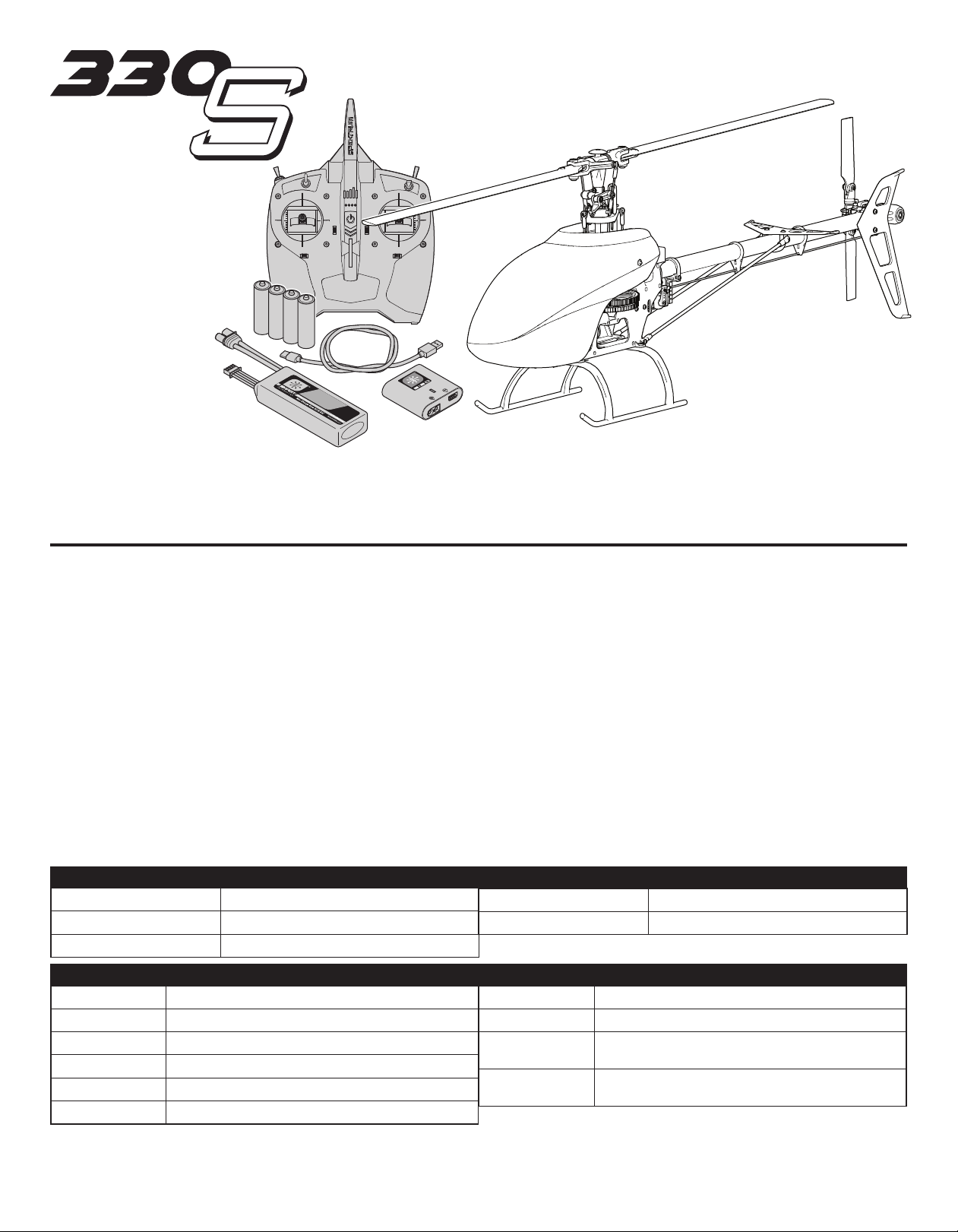
Box Contents
• Blade 330 S
• 3S 11.1V 2200mAh 30C IC3 Smart Li-Po Battery (RTF Only) (SPMX22003S30)
• DC Li-Po Balancing Smart Charger (RTF Only) (SPMXC1020)
• Spektrum DXS Transmitter (RTF Only) (SPMR1010)
• 4 AA Batteries (RTF Only)
Table of Contents
First Flight Preparation ....................................................................................... 4
Flying Checklist .................................................................................................. 4
Charging Warnings ............................................................................................. 4
Battery Charging ............................................................................................... 4
Installing the DXS Transmitter Batteries (RTF) ..................................................... 5
DXS Transmitter Control (RTF) ............................................................................ 5
Transmitter Setup Table (BNF) ............................................................................ 6
LED Indicator on Flight Controller ....................................................................... 6
SMART Throttle (BNF Only) ................................................................................. 6
Installing the Flight Battery ................................................................................. 7
Transmitter and Receiver Binding ....................................................................... 7
SAFE Technology ................................................................................................8
Flight Mode and Rate Selection .......................................................................... 8
Panic Recovery .................................................................................................. 8
Throttle Hold ...................................................................................................... 8
Control Tests ...................................................................................................... 9
Low Voltage Cutoff (LVC) .................................................................................. 10
Electronic Speed Controller Governor Operation .............................................. 10
Specifications
Length
Height
Main Rotor Diameter
27.7 in (655mm)
8.8 in (223mm)
28.5 in (721mm)
Understanding the Primary Flight Controls........................................................ 10
Pre-Flight Checklist ......................................................................................... 11
Flying the Blade 330 S Helicopter ..................................................................... 11
Gyro Gain Adjustment ....................................................................................... 11
Tail Belt Tension .............................................................................................. 11
Post-Flight Inspections and Maintenance ......................................................... 12
Advanced Tuning (Forward Programming) ........................................................ 12
Advanced Tuning (Non-Forward Programming) ................................................. 13
Troubleshooting Guide ...................................................................................... 14
Limited Warranty .............................................................................................. 15
Warranty and Service Contact Information ........................................................ 16
FCC Information ............................................................................................... 16
IC Information .................................................................................................. 16
Compliance Information for the European Union ............................................... 16
Exploded View ............................................................................................ 62–63
Parts List....................................................................................................64–65
Optional Parts ............................................................................................ 66–67
Tail Rotor Diameter
Flying Weight
6 in (152mm)
30.4 oz (773 g)
Components
Airframe
Motor
Receiver
Flight Controller
ESC
Battery
If you own this product, you may be required to register with the FAA. For up-to-date information on how to register with the FAA, please visit
https://registermyuas.faa.gov/. For additional assistance on regulations and guidance on UAS usage, visit knowbeforeyoufly.org/.
Blade® 330 S
440X Brushless Outrunner, 4200Kv (EFLH1360HA)
Serial Telemetry Receiver (SPM4651T)
Helicopter Flybarless Flight Control (SPMFC6250HX)
Smart 30-Amp (SPMXAE1030)
3S 11.1V 2200mAh Smart 30C Li-Po IC3® (SPMX22003S30)
Charger
Transmitter
Swash Servos
Tail Servo
S120 USB-C Smart Charger (RTF Only) (SPMXC1020)
Spektrum DXS Transmitter (RTF Only) (SPMR1010)
Spektrum H3055 Mid-Torq Ultra-Speed Micro Heli Cyclic
Servo
Spektrum H3065 Mid-Torq Ultra-Speed Micro Heli Tail
Servo
3
EN
Page 4
First Flight Preparation
Flying Checklist
• Remove and inspect contents
• Begin charging the flight battery
• Install the flight battery in the helicopter (once it has been fully charged)
• Program your computer transmitter
• Bind your transmitter (BNF only)
• Familiarize yourself with the controls
• Find a suitable area for flying
Charging Warnings
The Battery Charger (SPMXC1020) included with your helicopter has been designed
to safely charge the Li-Po battery.
NOTICE: All instructions and warnings must be followed exactly. Mishandling
of Li-Po batteries can result in a fire, personal injury and/or property damage.
• NEVER LEAVE CHARGING BATTERIES UNATTENDED.
• NEVER CHARGE BATTERIES OVERNIGHT.
• By handling, charging or using the included Li-Po battery, you assume all risks
associated with lithium batteries.
• If at any time the battery begins to balloon or swell, discontinue use immediately. If
charging or discharging, discontinue and disconnect. Continuing to use, charge or
discharge a battery that is ballooning or swelling can result in fire.
• Always store the battery at room temperature in a dry area for best results.
• Always transport or temporarily store the battery in a temperature range of 40–
120º F (5–49° C). Do not store battery or model in a car or direct sunlight. If stored
in a hot car, the battery can be damaged or even catch fire.
• Always charge batteries away from flammable materials.
Battery Charging
The recommended battery for the Blade® 330 S, included with the RTF version, is
an 11.1V, 3200mAh 3S 30C Smart Technology LiPo battery with an IC3® connector (SPMX32003S30). If using a different battery, the battery should be of similar
capacity, dimensions and weight to fit in the fuselage. The aircraft electronic speed
control is equipped with an IC3 device connector. Ensure the battery chosen is
compatible. Always ensure the model balances at the recommended center of
gravity (CG) with the chosen battery. Follow your chosen battery and battery charger instructions to charge the flight battery.
RTF Smart Technology Battery and S120 Charger, Specications
and Operation
The Spektrum S120 SMART Technology battery charger included with the RTF version of the aircraft is compatible only with Spektrum SMART 2-3 cell LiPo batteries
or 6-7 cell NiMH batteries. It is not compaptible with any other battery chemistries
or non-SMART batteries.
A USB power supply is required for use. A USB-C QC type power supply is recommended for the fastest charge times.
S120 Specications
Input USB Type C, power supply not included
Input Voltage 5V-12V
Charge Power 18W max (dependant on power supply)
Compatible USB Power Adaptor
Battery Connector IC3® and balance connector
Battery Types LiPo, NiMH (Spektrum SMART Batteries only)
Cell Count 2-3 cell LiPo, 6-7 cell NiMH
Max Output Voltage 13.05V
Max Output Current Up to 2A
USB-C port LED Indicator
5V/1A, 5V/2A, USB Quick Charge (QC)
2.0/3.0
Balance Port
IC3 Charge Port
❏ Always turn the transmitter on first
❏ Plug the flight battery into the lead from the ESC
❏ Allow the ESC to initialize and arm properly
❏ Fly the model
❏ Land the model
❏ Unplug the flight battery from the ESC
❏ Always turn the transmitter off last
• Always inspect the battery before charging.
• Always disconnect the battery after charging, and let the charger cool between
charges.
• Always constantly monitor the temperature of the battery pack while charging.
• ONLY USE A CHARGER SPECIFICALLY DESIGNED TO CHARGE LI-PO BATTERIES.
Failure to charge the battery with a compatible charger may cause a fire resulting
in personal injury and/or property damage.
• Never discharge Li-Po cells to below 3V under load.
• Never cover warning labels with hook and loop strips.
• Never leave charging batteries unattended.
• Never charge batteries outside recommended levels.
• Never charge damaged batteries.
• Never attempt to dismantle or alter the charger.
• Never allow minors to charge battery packs.
• Never charge batteries in extremely hot or cold places (recommended between
40–120° F or 5–49° C) or place in direct sunlight.
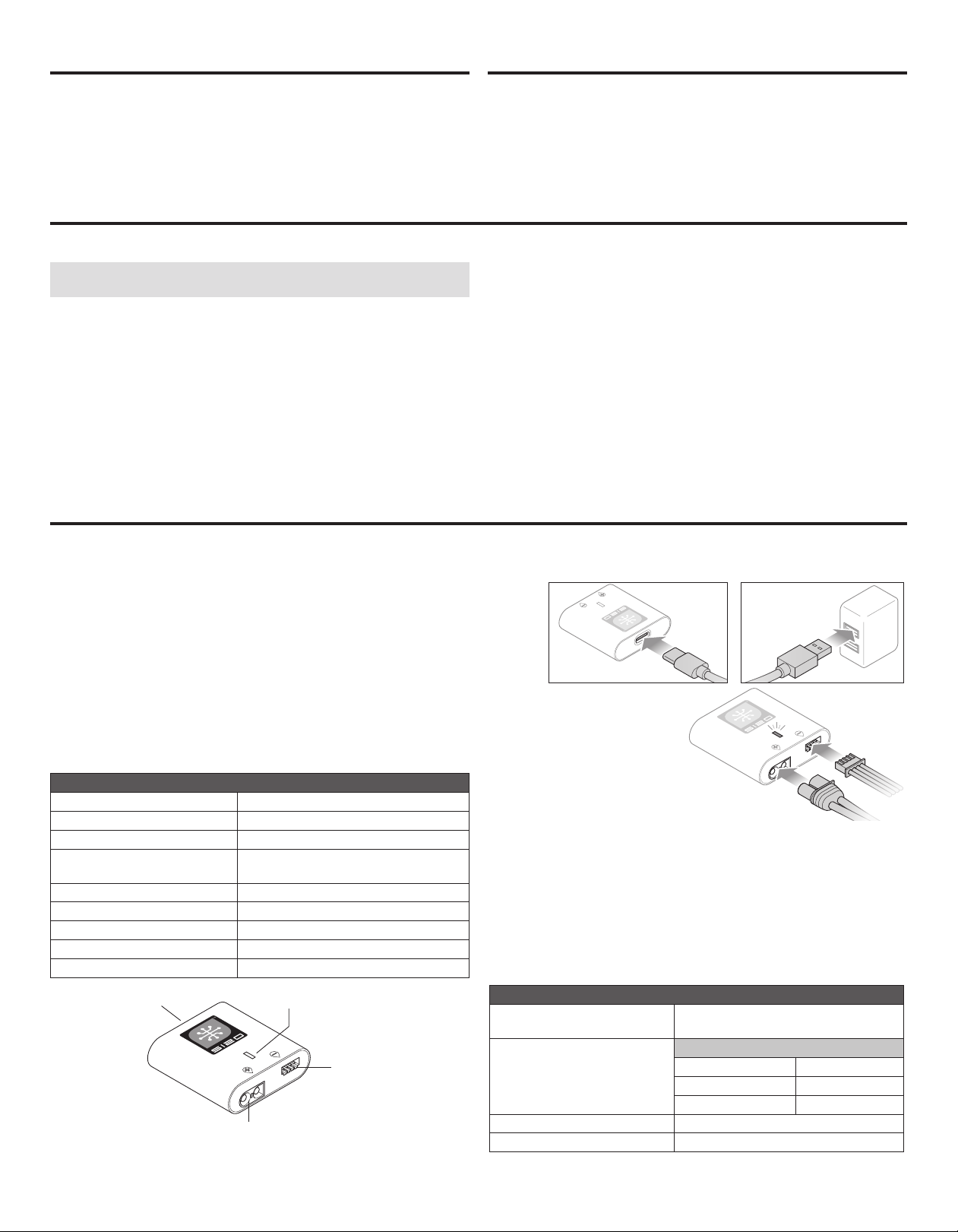
To charge the included flight battery:
1. Using the supplied Type-C USB cable, connect the S120 charger to a USB
power supply (not included).
2. Insert the Spektrum SMART
Battery IC3 connector (A) into the
charger IC3 port, and insert the
battery balance lead (B) into the
charger balance port. Both the
IC3 and balance connectors must
be connected for the charging
process to begin. The battery may
be disconnected from the charger
at any time to stop the charging
process.
IMPORTANT: SMART NiMH batteries do not have a balance connector.
3. Disconnect the IC3 and balance connectors when the charge and balance
cycles are complete, as indicated by the LED.
4. The LED indicator will glow solid red to indicate a charging error. Follow the
operation steps to ensure proper connection is used to charge the battery.
Refer to the LED indicator table for charger status.
IMPORTANT: Connecting a non-SMART battery will cause a charge error and the
S120 will not recognize or charge the battery.
LED Indicator
Power On
LiPo: Purple LED
NiMH: Yellow LED
Charge Complete Green LED (Solid)
Error Red LED (Solid)
USB 5V: White LED
USB Quick Charge 2.0/3.0: Blue LED
Less Than 25% Single Flash
25% – 75% Double Flash
76% – 99% Triple Flash
A
Battery Capacity
B
EN
4
Page 5
Installing the DXS Transmitter Batteries (RTF)
The LED indicator flashes and the transmitter beeps progressively faster as the
battery voltage drops.
Replace the transmitter batteries when the transmitter begins to beep.
CAUTION: NEVER remove the transmitter batteries while the model is
powered on. Loss of model control, damage or injury may occur.
CAUTION: If using rechargeable batteries, charge only rechargeable
batteries. Charging non-rechargeable batteries may cause the batteries
to burst, resulting in injury to persons and/or damage to property.
CAUTION: Risk of explosion if battery is replaced with an incorrect type.
Dispose of used batteries according to national regulations.
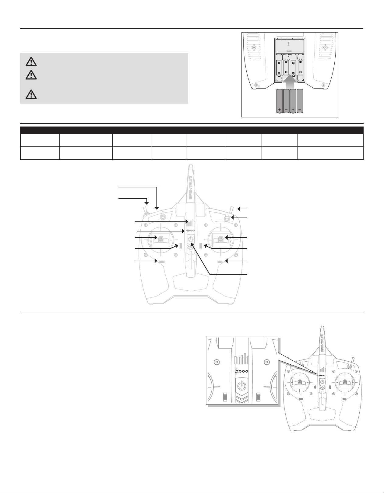
DXS Transmitter Control (RTF)
A B C D E F G
Mode 1
Mode 2
Aileron (Left/Right)
Throttle (Up/Down)
Aileron (Left/Right)
Elevator (Up/Down)
Bind/Panic Switch
Fli ght Mode Switch
0 = Stability Mode (NORM)
1 = Intermediate Mode (FM1)
2 = Agility Mode (FM2)
Flight Battery level Indicator
Throttle Trim Aileron Trim ON/OFF Switch Rudder Trim Elevator Trim
Elevator Trim Aileron Trim ON/OFF Switch Rudder Trim Throttle Trim
LED Indicator
G
Rudder (Left/Right)
Elevator (Up/Down)
Rudder (Left/Right)
Throttle (Up/Down)
Throttle Hold
Du al Rate Switch
A
F
E
Battery Voltage Level
The included DXS transmitter includes a new flight battery voltage level indicator
feature.
LED SMART Battery voltage indication is based on current voltage and will change
with throttle/power usage. When throttle is increased, voltage drops, causing the
bars to indicate lower power (e.g., fewer LEDs solid or flashing.) When the throttle
is lowered to idle/off, the bars recover (e.g., more LEDs solid or flashing). LED bars
will rise and lower depending on throttle/power usage.
The SMART Battery low voltage alarm sounds when the ESCs are close to reaching
low voltage cutoff. The alarm will sound for 25 seconds. If the throttle is lowered to
allow voltage recovery, the alarm will stop early. Land the aircraft when the alarm
sounds.
After landing, reset the SMART Battery low voltage warning by either (1) powering
cycling the DXS transmitter, or (2) disconnecting the battery from the aircraft for
more than 15 seconds or until the LED voltage indication bars go out.
Connect a fully charged battery to the aircraft, which will ensure the SMART Battery low voltage warning resets prior to the next flight.
B
C
D
5
EN
Page 6

Transmitter Setup Table (BNF)
DX6e, DX6, DX7, DX8, DX9, DX18, DXs0, iX12, iX20, NX6, NX8, NX10
SYSTEM SETUP
Model Type HELI
Swash Type Normal
F-Mode Setup
Switch 1 Switch B
Switch 2 Inhibit
Hold Switch Switch H
0 1
Channel Assign
Channel Input Cong
1 Throttle
2 Aileron
3 Elevator
4 Rudder
5 Gear F-Mode
6 Collective
7 AUX 2
Frame Rate
11ms
DSMX
Panic Mode Operation
Bind / I Button
Pressed = Panic Mode On
Released = Panic Mode Off
FUNCTION LIST
Servo Setup
Chan Travel Reverse
THR 100/100 Normal
AIL 100/100 Normal
ELE 100/100 Normal
RUD 100/100 Normal
GER 100/100 Normal
D/R & Expo Throttle Curve
Chan Sw (F) Pos D/R Expo Sw (B) Pos Pt 1 Pt 2 Pt 3 Pt 4 Pt 5
0 100/100 +25 N 0 65 65 65 65
AILE
ELEV
RUDD
Gyro
Timer
Mode Count Down
Time 5:00v
Start Throttle Out
Over 25%
One Time Inhibit
1 100/100 +25 1 80 80 80 80 80
2 75/75 +25 2 100 100 100 100 100
0 100/100 +25 Pitch Curve
1 100/100 +25 Sw (B) Pos Pt 1 Pt 2 Pt 3 Pt 4 Pt 5
2 75/75 +25 N 30 40 50 75 100
0 100/100 +25 1 0 25 50 75 100
1 100/100 +25 2 0 25 50 75 100
2 75/75 +25 HOLD 25 37 50 75 100
Inhibit
Chan Travel Reverse
PIT 100/100 Normal
AX2 100/100 Normal
AX3 100/100 Normal
AX4 100/100 Normal
Mixing
Normal
Channels -I- > Ger
P-Mix 1
Rate 0/–125
Offset 100
Switch Switch I
Position 0 1
LED Indicator on Flight Controller
LED Indicator on FC Indicator Description
Slow Green Flash Ready to Fly
Slow Red Flash
Slow Blue Flash
Yellow Flash (during calibration) Calibration proceeding normally
Red Flash
(during calibration) Calibration Error, FC not level or is being moved during calibration
SMART Throttle (BNF Only)
The new line of Spektrum ESCs feature a telemetry function called SMART Throttle.
SMART Throttle technology combines the throttle signal with telemetry data from
the ESC on one normal three wire servo connector.
SMART Throttle ESCs can send current, voltage, ESC temp, and mAh consumed.
They can also pass along battery data from compatible Spektrum SMART batteries. SMART Throttle telemetry data shows up on your transmitter like any other
telemetry sensor.
For SMART Throttle to function you must have a SMART Throttle ESC paired with
a SMART Throttle telemetry receiver, and a Spektrum DSMX transmitter with
telemetry. Only certain Spektrum products include SMART technology compatibility, check your receiver and ESC manual for more information. An update for your
transmitter may be required for SMART features.
(See www.spektrumrc.com to register and update your transmitter.)
To activate SMART Telemetry:
1. Keep the vehicle powered on after binding the transmitter to the receiver.
2. Scroll to the Telemetry screen.
3. Scroll to Settings.
4. Select Auto Config.
Failsafe Active
Forward Programming Mode
To activate Speed infomation using SMART Telemetry:
5. After doing the initial SMART telemetry configuration,
keep the vehicle powered on.
6. Scroll to the Telemetry screen.
7. Scroll to SMART ESC and double select.
8. Scroll down to NEXT.
9. Enter the values for the magnetic pole count of the motor and the gear ratio
(motor and gear ratio information can be found in the manual for your vehicle).
When the radio is on and connected to a receiver sending SMART Data, the SMART
Logo will appear under the battery logo on the home page and a signal bar will
appear in the top left corner of the screen. Scrolling down, past the servo monitor,
the SMART screens will appear. Select either ESC, battery, or both for display to
suit your preference.
EN
6
Page 7
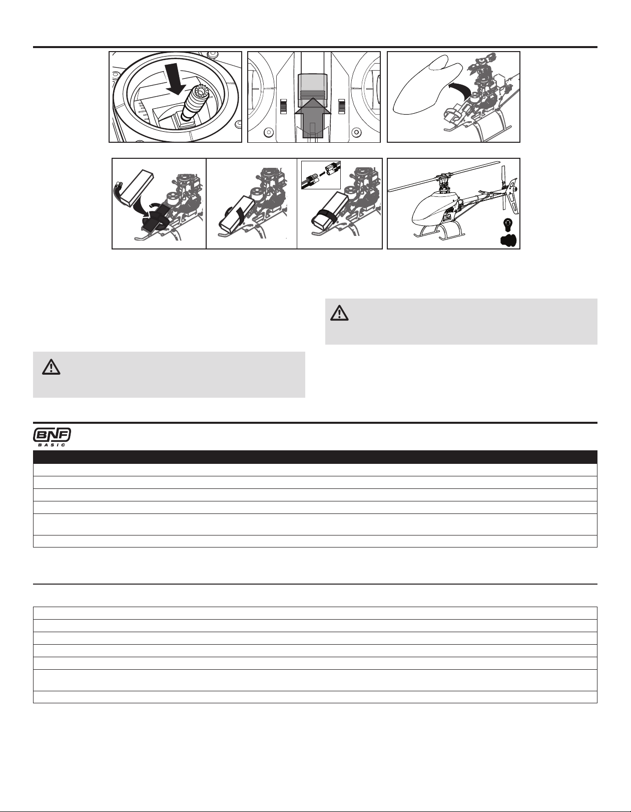
Installing the Flight Battery
1. Lower the throttle.
2. Power on the transmitter.
3. Center all trims.
4. To allow the ESC to arm and to keep rotors from initiating at startup, turn on
throttle hold and normal flight mode before connecting the flight battery.
5. Attach hook material to the helicopter frame and loop material to the battery.
6. Install the flight battery on the helicopter frame. Secure the flight battery with a
hook and loop strap. Connect the battery cable to the ESC.
CAUTION: Make sure the flight battery, wire and connector does not
come into contact with the motor. Failure to do so will cause the motor,
ESC and battery to overheat, resulting in a crash causing property damage
and injury.
7. The swashplate will center, indicating that the unit is ready. The flight controller
status LED will display a slow green flash once initialization has been
completed.
8. The helicopter motor will emit a series of tones, indicating the ESC is armed.
CAUTION: Always disconnect the Li-Po battery from the ESC power lead
when not flying to avoid over-discharging the battery. Batteries
discharged below the lowest approved voltage may become damaged,
resulting in loss of performance and potential fire when batteries are charged.
Transmitter and Receiver Binding
Binding is the process of programming the receiver to recognize the GUID (Globally Unique Identifier) code of a single specific transmitter. You need to ‘bind’
®
your chosen Spektrum™ DSM2®/DSMX® technology equipped aircraft transmitter to the receiver for proper operation.
Binding Procedure
1. Program your transmitter using the Transmitter Setup found in this manual.
2. Connect the flight battery to the ESC.
3. Press the bind button on the remote receiver to initiate binding. The orange LED on the receiver will begin flashing rapidly to indicate bind mode.
4. Move the throttle stick to the low throttle position in normal mode.
5. Follow the procedures of your specific transmitter to enter bind mode. The system will connect within a few seconds. Once connected, the orange LED on the
receiver will come on solid orange.
6. Disconnect the flight battery.
If you encounter problems, obey binding instructions and refer to transmitter troubleshooting guide for other instructions.
If needed, contact the appropriate Horizon Product Support office.
RTF
1. Lower the throttle stick to the lowest position. Set all trims to the center position.
2. Power off the transmitter.
3. Connect the flight battery to the ESC, and press the bind button on the remote receiver.
4. Press and hold the Bind Switch while powering on the transmitter.
5. The transmitter will beep and the LED will blink. Release the Bind Switch.
6. The helicopter is bound when the LED on the receiver control unit is solid and the transmitter emits 3 rapid, high-pitch tones.
7. Disconnect the flight battery and power the transmitter off.
If you encounter problems, obey binding instructions and refer to the troubleshooting guide for other instructions.
If needed, contact the appropriate Horizon Product Support office.
Your RTF transmitter comes prebound to the model. If you need to re-bind, follow the directions below.
If the transmitter emits 2 low-pitch tones, the binding procedure was not successful and should be attempted again.
7
EN
Page 8

Technology
Revolutionary SAFE® (Sensor Assisted Flight Envelope) technology uses an innovative combination of multi-axis sensors and software that allows model aircraft
to know its position relative to the horizon. This spatial awareness is utilized to
create a controlled flight envelope the aircraft can use to maintain a safe region
of bank and pitch angles so you can fly more safely. Far beyond stability, this level
of protection offers multiple modes so the pilot can choose to develop his or her
skills with a greater degree of security and flight control that always feels crisp
and responsive.
Flight Mode and Rate Selection
SAFE technology delivers:
• Flight envelope protection you can enable at the flip of a switch.
• Multiple modes let you adapt SAFE technology to your skill level instantly.
Best of all, sophisticated SAFE technology doesn’t require any work to enjoy. Every
aircraft with SAFE installed is ready to use and optimized to offer the best possible
flight experience.
FlySAFERC.com
In Stability Mode the bank angle is limited. When the cyclic stick is released the
model will return to level.
In Intermediate Mode the bank angle is not limited. When the cyclic stick is
released the model will not return to level. This mode is great for learning forward
flight and basic aerobatics such as stall turns and loops.
Panic Recovery
If you get into distress while flying in any mode, activate the panic function and
move the control sticks to their neutral position. SAFE technology will immediately
return the aircraft to an upright level attitude, if the aircraft is at a sufficient height
with no obstacles in its path. Return the collective stick to 50% and deactivate the
Panic Recovery Function to return to the current flight mode.
Throttle Hold
Throttle hold only turns off the motor on an electric helicopter. You maintain pitch
and direction control.
The blades will spin if throttle hold is OFF. For safety, turn throttle hold ON any time
you need to touch the helicopter or check the direction controls.
In Agility Mode the bank angle is not limited. When the cyclic stick is released the
model will not return to level. This mode is great for 3D aerobatics such as stationary flips and tic tocs.
Change rates in any mode by moving the two-position dual rate switch.
• Low rate reduces the control rates, providing an easier to fly model.
Beginners should use low rate for initial flights.
• High rate provides full control and should be used by intermediate
and experience pilots.
NOTICE: Before deactivating Panic Recovery , make sure the collective stick has
been returned to the 50% position. Once the Panic Recovery has been deactivated, full negative collective becomes available, which could cause the 330 S
Smart to descend rapidly.
• This mode is intended to provide the pilot with the confidence to continue to
improve their flight skills.
• Move the collective stick to 50% and return all other transmitter controls to
neutral for the quickest recovery.
• Once the model has reached a level upright attitude, the negative collective is
reduced to prevent the user from pushing the model into the ground.
Throttle hold is also used to turn off the motor if the helicopter is out of control, in
danger of crashing, or both.
EN
8
Page 9

Control Tests
CAUTION: You must complete the Tail Rotor and Cyclic tests prior to every flight. Failure to complete the tests and ensuring the sensor corrects in the proper
direction can cause the helicopter to crash, resulting in property damage and injury.
Tail Rotor
1. Power on the transmitter.
2. Turn TH HOLD ON and put transmitter in normal mode.
3. Connect the flight battery to the ESC.
4. Once initialization is complete the LED on the FC6250HX will begin flashing
green.
Cyclic
It is normal for the swashplate to slowly move back to its original position
after a stick input and for the servos to not move at the same speed as your
control sticks.
5. Move the rudder stick to the right. The pitch
slider on the tail shaft should move toward
the tail case. If the pitch slider moves in the
opposite direction, ensure the rudder channel reverse setting within the transmitter is
set to normal.
6. Release the rudder control. Manually turn
the helicopter nose to the left. The flight
controller should compensate by moving
the tail slider towards the tail case.
• Tilt the helicopter forward. The swashplate must tilt backward.
• Tilt the helicopter backward. The swashplate must tilt forward.
• Roll the helicopter left. The swashplate must roll right.
• Roll the helicopter right. The swashplate must roll left.
Cyclic and Collective Control Test
Ensure the throttle hold is ON when performing the direction control tests.
Test the controls prior to each flight to ensure the servos, linkages and parts
Elevator
Left Side View Left Side View
Aileron
operate correctly. If the controls do not react as shown in the illustrations below,
confirm the transmitter is programmed correctly before continuing on to the Motor
Test.
Rear ViewRear View
Collective Pitch
Climb
Rear ViewRear View
Descend
9
EN
Page 10

Motor Test
Place the helicopter outdoors on a clean, flat and level surface (concrete or
asphalt) free of obstructions. Always stay clear of moving rotor blades.
1. The motor will emit a series of tones when the helicopter’s ESC arms properly.
Before continuing, confirm TH HOLD is ON.
WARNING: The motor will spin when throttle is increased while TH
HOLD is OFF.
2. Check the swashplate directions to ensure they are moving in the correct
direction. Please refer to the diagrams above for reference.
Low Voltage Cutoff (LVC)
WARNING: Stay at least 30 feet (10 meters) away from the helicopter
when the motor is running. Do not attempt to fly the helicopter at this
time.
3. Ensure the throttle is lowered completely. Confirm the transmitter is still set
to normal flight mode. Turn throttle hold off at this time. Slowly increase the
throttle until the blades begin to spin. The main blades spin clockwise when
viewing the helicopter from the top. The tail rotor blades spin counterclockwise
when viewing the helicopter from the right-hand side.
The ESC will continuously lower power to the motor until complete shutdown when
the battery reaches 12V under load. This helps prevent over-discharge of the Li-Po
battery. Land immediately when the ESC activates LVC. Continuing to fly after LVC
can damage the battery, cause a crash or both. Crash damage and batteries damaged due to over-discharge are not covered under warranty.
Repeatedly flying the helicopter until LVC activates will damage the helicopter battery.
Disconnect and remove the Li-Po battery from the aircraft after use to prevent trickle
discharge. During storage, make sure the battery charge does not fall below 3V per
cell.
Electronic Speed Controller Governor Operation
The Blade 330 S Electronic Speed Controller (ESC) utilizes a head speed governor
to maintain a constant head speed during flight. The governor will work to maintain
a constant head speed throughout maneuvers and the discharge cycle of the flight
battery.
The throttle position determines the requested head speed, and although throttle
curves are still used, they will be a constant value; all positions of the curve are
set to the same value. The lowest position of the normal flight mode throttle curve
must be set to 0 to ensure the motor can be disabled.
The default throttle curve settings listed in the transmitter setup tables should be
acceptable to most pilots and we recommend starting with these values. If you feel
an adjustment is necessary after a few flights, adjust the throttle percentage for
the desired flight mode. We recommend making small changes of 5% to find your
preferred head speed.
Remember the throttle position on the transmitter is simply requesting a specific
head speed and this is not related to the actual motor power percentage.
Understanding the Primary Flight Controls
If you are not familiar with the controls of your 330 S, take a few minutes to familiarize yourself with them before attempting your first flight.
Collective
Left Side View
Top ViewTop View
Throttle up
Rudder
Left Side View
Descend
Climb
Throttle down
EN
Rudder left
Elevator
Elevator forward
Aileron
Aileron left
Nose Yaws Left
Left Side View
Forward
Rear View
Left
10
Rudder right
Elevator back
Aileron right
Nose Yaws Right
Left Side View
Backward
RearView
Right
Page 11

Pre-Flight Checklist
❏ Check all screws and ensure that they are tight
❏ Check belt tension and ensure that it is not too tight or too loose
❏ Check main and tail blades to ensure they are not damaged
❏ Check all links and make sure they move freely but do not pop off easily
❏ Check that flight battery and transmitter battery are fully charged
❏ Check all wires to ensure that they are not cut, pinched, or chaffed
and are properly secured
❏ Check all wire connections
Flying the Blade 330 S Helicopter
Consult local laws and ordinances before choosing a location
to y your aircraft.
Select a large, open area away from people and objects. Your first flights should
be outdoors in low-wind conditions. Always stay at least 30 feet (10 meters) away
from the helicopter when it is flying.
The Blade 330 S is intended to be flown outdoors by experienced pilots.
Takeoff
Deliberately increase throttle and establish a hover at least 24” (0.6 meter) high,
outside of ground effect.
CAUTION: Making large inputs to the roll or pitch controls while the
helicopter is on the ground may result in a crash.
Flying
The helicopter lifts off the ground when the rotor head reaches a suitable speed.
Establish a low-level hover to verify proper operation of your helicopter.
First flights should be performed in normal mode and low cyclic and rudder dual
rates until you are familiar with the flying manner of the helicopter.
❏ Check gears and make sure no teeth are missing
❏ Do a complete control test
❏ Verify the receiver sensor is correcting in the proper directions
❏ Check that servos are functioning properly
❏ Check to make sure the flight battery is properly secured
❏ Check to make sure receiver is properly secured
CAUTION: Always fly the helicopter with your back to the sun and the
wind to prevent loss of flight control.
Landing
Establish a low level hover. Deliberately lower the throttle until the
helicopter lands.
When the helicopter is in stunt mode:
• The rotor head speed is constant.
• The main rotor will increase negative pitch as the throttle/collective stick is
moved from the middle stick position to the low stick position. Negative pitch
allows the helicopter to fly upside down and perform aerobatics.
Change between stunt and idle up modes in a hover with the throttle near the
hovering stick position.
WARNING: Do not use wooden main blades with the Blade 330 S or
injury and/or property damage could occur. Only use Blade 330 S
replacement carbon fiber main blades.
Gyro Gain Adjustment
If the tail wags or oscillates, lower the gain on the gyro.
• On your transmitter’s gyro menu, decrease the gyro gain values a small amount
at a time until the helicopter is stable within a particular flight mode.
If the tail is drifting while hovering, increase the gain on the gyro.
• On your transmitter, increase the gyro gain values a small amount at a time until
the tail starts to wag/oscillate. Afterwards, reduce the gain until the tail stops
wagging/oscillating within a particular flight mode.
Tail Belt Tension
Belt tension that is too tight results in loss of power and causes the belt to wear more quickly. Tension that is too loose can cause belt damage and loss of tail rotor
control in flight.
To check for proper belt tension:
1. View the tail rotor drive belt through the opening at the back of the main frame.
2. Use a hex wrench or standard screwdriver to compress the belt through the
opening.
3. Apply light pressure on the belt, compressing the belt toward the left side of
the tail boom.
4. The belt tension is correct if the compressed side of the belt reaches approximately halfway to the opposite side of the belt.
• If the compressed side of the belt reaches farther than halfway to the other side
of the belt, the tension is too loose.
• If the compressed side of the belt does not reach halfway to the other side of
the belt, the tension is too tight.
To adjust belt tension:
1. Loosen the two horizontal stabilizer screws.
2. Loosen the 4 screws at the back of the main frame.
3. Slide the boom forward or aft to adjust the belt tension.
4. When the belt tension is properly adjusted, tighten the 4 screws at the back
of the frame.
5. Tighten the horizontal stabilizer screws.
11
EN
Page 12

Post-Flight Inspections and Maintenance
Ball Links
Cleaning Make sure the battery is not connected before cleaning. Remove dust and debris with a soft brush or a dry lint free cloth.
Bearings Replace bearings when they become damaged.
Wiring Make sure wiring does not block moving parts. Replace damaged wiring and loose connectors.
Fasteners
Rotors
Flight Controller
Make sure the plastic ball link holds the control ball, but is not tight (binding) on the ball. When a link is too loose on the ball, it can separate
from the ball during flight and cause a crash. Replace worn ball links before they fail.
Make sure there are no loose screws, other fasteners or connectors. Do not over tighten metal screws in plastic parts. Tighten screw so
parts are mated together, then turn screw only 1/8th of a turn more.
Make sure there is no damage to rotor blades and other parts which move at high speed. Damage to these parts includes cracks, burrs,
chips or scratches. Replace damaged parts before flying.
Make sure the receiver is securely attached to the frame. Replace the double-sided tape when necessary. The helicopter will crash if the
receiver separates from the helicopter frame.
Advanced Tuning (Forward Programming)
Applies to forward programming capable Spektrum Transmitters including DX6G2, DX7G2, DX8G2, DX9, iX12, DX18, DX20
The Blade 330 S default settings are appropriate for most users. We recommend
flying with the default parameters before making any adjustments.
The Blade 330 S BNF flight controller may be programmed from any compatible
Spektrum transmitter (visit SpektrumRC.com for more information).
The flight controller shipped with BNF models has a range of adjustable
parameters suitable for the Blade 330 S Helicopter and is not intended for use in
other aircraft.
Entering the Advanced Parameters Menu
With the helicopter bound to the transmitter and powered on, enter the Function List and select Forward Programming. The list of adjustable parameters and the range of
values available for tuning have been tailored for this helicopter. Make small changes to one parameter at a time and test fly the changes before changing the parameter
further or changing a different parameter.
It is important to use the included servos with the BNF flight controller because
the adjustable parameters available for the SPMFC6250HX are designed around
the recommended servos. It is possible there may not be enough range for the
helicopter to be tuned when using alternative servos.
Calibration Procedure
If the helicopter is experiencing drift issues, perform the following calibration. The calibration procedure may also be needed following crash repairs.
1. Ensure the surface used for calibration is level.
2. Power on the transmitter and activate throttle hold.
3. Connect the flight batter to the ESC and allowing the model to initialize.
4. Turn Throttle Hold ON.
5. Using a bubble level as shown below, level the helicopter by placing a shim under
the landing skid.
Bubble level
Shim
6. Enter the Function List on your transmitter.
7. Select Forward Programming.
8. Select System Setup.
9. Select Calibration.
10. Select Apply and the calibration will begin. The LED will flash yellow indicating
the calibration is proceeding normally. If the LED changes to red this indicates
the model is not near level or the model was moved, in this case the calibration
starts over.
11. After the calibration is successfully completed, the receiver LED will will
change to a slow green flash which indicates the calibration has completed.
12. Proceed to the pre-flight check list procedure before flying your model.
Factory Reset
If the process of tuning the Blade 330 S helicopter results in undesirable flight performance, you can reset the settings back to factory defaults by selecting the Factory
Reset option in Forward Programming.
1. Enter the Function List
2. Select Forward Programming
3. Select System Setup
4. Select Factory Reset
5. Select Apply
6. Perform the Setup->Swashplate->Sub Trim function and ensure the servos are
properly trimmed.
7. Proceed with the pre-flight check list procedure before flying the model.
EN
12
Page 13

Advanced Tuning (Non-Forward Programming)
Applies to Spektrum transmitters not capable of forward programing
including DX6i, DX6e, DX7s DX8, and DX8e
Your Blade 330 S was setup at the factory and test flown. The servo adjustment
steps are usually only necessary in special circumstances, such as after a crash or
if a servo or linkage is replaced.
For pilots flying with a transmitter not capable of forward programming use the
following procedures to make servo adjustments and perform the calibration
procedure.
The advanced tuning options must be entered within 30 seconds after initialization
completes. In addition the combination of dual rates and travel adjustments must
result in a throw greater than 65% in order to enter the tuning modes.
Entering Servo Adjustment Mode
1. Lower the throttle stick to the lowest position.
2. Power ON the transmitter and activate throttle hold.
3. Install the flight battery on the helicopter frame,
securing it with the hook and loop strap.
4. Connect the battery connector to the ESC.
5. After initialization is complete (indicated by a slow green flash), hold the left
stick to the bottom left corner and the right stick to the bottom right corner as
shown.
6. Servo Adjustment Mode is indicated by the swashplate servos jumping and then
slowly moving back to center.
7. Release the sticks and proceed to the next step.
Adjusting the Servo Neutral Position
With the model in Servo Adjustment Mode, the control stick and gyro inputs are
disabled and the servos are held in the neutral position. Check the position of the
servo arms to verify they are perpendicular to the servos.
• If the arms are perpendicular to the servos, no adjustment is necessary.
Exit Servo Adjustment Mode.
• If one or more servo arm is not perpendicular to the servos, continue the servo
adjustment process.
While watching the swashplate servos, apply fore or aft cyclic and release. One
of the servos will jump, indicating the selected servo. Apply fore or aft cyclic and
release until the servo that needs to be adjusted is selected.
Once the servo you wish to adjust is selected, move the cyclic stick left or right to
adjust the servo neutral position in the desired direction.
To reset the current servo to the default neutral position, hold the rudder stick full
right for two seconds.
The range of adjustment is limited. If you are unable to adjust the servo arm to be
perpendicular to the servo, you must reset the servo to the default neutral position,
remove the servo arm and place it back onto the servo as close to perpendicular
as possible. You may then adjust the servo neutral position using left or right cyclic
stick.
Swashplate Leveling
Before saving your adjustments and exiting servo adjustment mode, verify the
swashplate is level and both main rotor blades are at 0 degrees pitch.
If they are not, make linkage adjustments as necessary.
Saving the Servo Adjustments
1. Lower the throttle stick to the lowest position and release the sticks.
2. Move the tail rotor stick to the left and hold for four seconds to exit Servo
Adjustment Mode. The servos will jump indicating a return to normal operation.
3. Release the tail rotor stick.
4. Perform the pre-flight checklist procedure before flying your model.
Control Input in Servo
Adjustment Mode
Fore/Aft Cyclic Select Previous or Next Servo
Right/Left Cyclic Increase or Decrease Sub Trim Adjustment
Right Tailrotor
Left Tailrotor and Low Throttle
Action in Servo Adjustment Mode
Hold For Two Seconds;
Neutral Position is Reset on Selected Servo
Hold for Four Seconds;
Exit Servo Adjustment Mode
Calibration Procedure
If the helicopter is experiencing drift issues after completing the trim flight procedure, perform the following calibration. The calibration procedure may also be
needed following crash repairs.
To perform the calibration procedure:
1. Ensure the surface used for calibration is level.
2. Power on the transmitter and helicopter, allowing them to initialize.
3. Turn Throttle Hold ON.
4. Ensure the main motor is disconnected.
5. Using a bubble level as shown below, level the helicopter by placing a shim under
the tail fin.
Bubble level
Shim
6. Hold the left stick to the bottom right corner, and the right stick to the upper left
corner.
7. The LED on the Flight Controller will flash yellow while caibrating
Do not move the helicopter until the calibration
is completed. If the LED displays a red LED an error has occurred. Begin the
calibration procedure again, starting with step 1.
LED Indicator on FC Indicator Description
Slow Green Flash Ready to Fly
Slow Red Flash
Slow Blue Flash
Yellow Flash (during calibration) Calibration proceeding normally
Red Flash
8. After the calibration is successfully completed, the receiver LED will blink
green.
(during calibration)
Calibration Error, FC not level or is being
Failsafe Active
Forward Programming Mode
moved during calibration
13
EN
Page 14

Troubleshooting Guide
Problem Possible Cause Solution
Helicopter will not bind
to the transmitter
(during binding)
Helicopter will not link to the transmitter
(after binding)
SPM4649T will not initialize
Helicopter will not respond to the throttle
but responds to other controls
Helicopter power is lacking
Helicopter will not lift off
Low flight battery or transmitter battery voltage Fully charge or replace the flight battery and/or transmitter batteries
receiver is not in bind mode Make sure the bind plug is connected to the receiver BND/DAT port
Transmitter is not in bind mode
Transmitter too close to the helicopter during binding process
Helicopter is bound to a different model memory
(ModelMatch™ radios only)
Flight battery/Transmitter battery charge is too low Replace or recharge batteries
The helicopter was moved during initialization Lay the helicopter on its side during initialization if windy
The transmitter is powered off Power on the transmitter
Controls are not centered Center elevator, aileron and rudder controls. Make sure the throttle is at idle
Throttle not at idle and/or throttle trim is too high Lower the throttle stick and lower the throttle trim
The transmitter is not in normal mode or throttle hold
is on
The motor is not connected to the ESC or the mo-
tor wires are damaged
Flight battery charge is too low Replace or recharge flight battery
Throttle channel is reversed Reverse the throttle channel on the transmitter
Flight battery has low voltage Fully charge the flight battery
Flight battery is old or damaged Replace the flight battery
Flight battery cells are unbalanced Fully charge the flight battery, allowing the charger time to balance the cells
Excessive current is being drawn through the BEC Check all servos and the helicopter motor for damage
Tail drive belt tension is not correct See "Checking Tail Drive Belt Tension" in this manual
Main rotor head is not spinning in the correct direction
Transmitter settings are not correct Check throttle and pitch curve settings and pitch control direction
Flight battery has low voltage Fully charge the flight battery
Power on the transmitter while holding the Trainer/Bind switch. Hold the Trainer/
Bind switch until binding is complete
Power off the transmitter. Move the transmitter further away from the helicopter.
Disconnect and reconnect the flight battery to the helicopter and follow binding instructions
Disconnect the flight battery. Select the correct model memory on the transmitter
Reconnect the flight battery
Make sure the transmitter is in normal mode and throttle hold is off
Connect the motor wires to the ESC and check motor wires for damage
Make sure the main rotor head is spinning clockwise. Refer to the motor control
test
The helicopter tail spins out of control
The helicopter wobbles in flight
Main rotor blades are installed backwards Install the main rotor blades with the thicker side as the leading edge
Rudder control and/or sensor direction reversed
Tail servo is damaged Check the rudder servo for damage and replace if necessary
Inadequate control arm throw Check the rudder control arm for adequate travel and adjust if necessary
Tail belt is too loose Make sure the tail drive belt tension is adjusted correctly
Cyclic gain is too high Please review the Advanced Settings - Gain Adjustments section
Headspeed is too low
Dampers are worn Replace the main rotor head dampers
Make sure the rudder control and the rudder sensor are operating in the correct
direction
Increase the helicopter's head speed via your transmitter settings and/or using a
freshly charged flight pack
EN
14
Page 15

Limited Warranty
What this Warranty Covers—Horizon Hobby, LLC, (Horizon) warrants to the original
purchaser that the product purchased (the “Product”) will be free from defects in
materials and workmanship at the date of purchase.
What is Not Covered—This warranty is not transferable and does not cover (i) cosmetic damage, (ii) damage due to acts of God, accident, misuse, abuse, negligence,
commercial use, or due to improper use, installation, operation or maintenance, (iii)
modification of or to any part of the Product, (iv) attempted service by anyone other
than a Horizon Hobby authorized service center, (v) Product not purchased from an
authorized Horizon dealer, (vi) Product not compliant with applicable technical regulations, or (vii) use that violates any applicable laws, rules, or regulations.
OTHER THAN THE EXPRESS WARRANTY ABOVE, HORIZON MAKES NO OTHER
WARRANTY OR REPRESENTATION, AND HEREBY DISCLAIMS ANY AND ALL IMPLIED
WARRANTIES, INCLUDING, WITHOUT LIMITATION, THE IMPLIED WARRANTIES OF
NON-INFRINGEMENT, MERCHANTABILITY AND FITNESS FOR A PARTICULAR PURPOSE.
THE PURCHASER ACKNOWLEDGES THAT THEY ALONE HAVE DETERMINED THAT
THE PRODUCT WILL SUITABLY MEET THE REQUIREMENTS OF THE PURCHASER’S
INTENDED USE.
Purchaser’s Remedy—Horizon’s sole obligation and purchaser’s sole and exclusive
remedy shall be that Horizon will, at its option, either (i) service, or (ii) replace, any
Product determined by Horizon to be defective. Horizon reserves the right to inspect
any and all Product(s) involved in a warranty claim. Service or replacement decisions
are at the sole discretion of Horizon. Proof of purchase is required for all warranty
claims. SERVICE OR REPLACEMENT AS PROVIDED UNDER THIS WARRANTY IS THE
PURCHASER’S SOLE AND EXCLUSIVE REMEDY.
Limitation of Liability—HORIZON SHALL NOT BE LIABLE FOR SPECIAL, INDIRECT,
INCIDENTAL OR CONSEQUENTIAL DAMAGES, LOSS OF PROFITS OR PRODUCTION OR
COMMERCIAL LOSS IN ANY WAY, REGARDLESS OF WHETHER SUCH CLAIM IS BASED
IN CONTRACT, WARRANTY, TORT, NEGLIGENCE, STRICT LIABILITY OR ANY OTHER
THEORY OF LIABILITY, EVEN IF HORIZON HAS BEEN ADVISED OF THE POSSIBILITY OF SUCH DAMAGES. Further, in no event shall the liability of Horizon exceed the
individual price of the Product on which liability is asserted. As Horizon has no control
over use, setup, final assembly, modification or misuse, no liability shall be assumed
nor accepted for any resulting damage or injury. By the act of use, setup or assembly,
the user accepts all resulting liability. If you as the purchaser or user are not prepared
to accept the liability associated with the use of the Product, purchaser is advised to
return the Product immediately in new and unused condition to the place of purchase.
Law—These terms are governed by Illinois law (without regard to conflict of law
principals). This warranty gives you specific legal rights, and you may also have other
rights which vary from state to state. Horizon reserves the right to change or modify
this warranty at any time without notice.
WARRANTY SERVICES
Questions, Assistance, and Services—Your local hobby store and/or place of
purchase cannot provide warranty support or service. Once assembly, setup or use
of the Product has been started, you must contact your local distributor or Horizon
directly. This will enable Horizon to better answer your questions and service you in
the event that you may need any assistance. For questions or assistance, please visit
our website at www.horizonhobby.com, submit a Product Support Inquiry, or call the
toll free telephone number referenced in the Warranty and Service Contact Information
section to speak with a Product Support representative.
Inspection or Services—If this Product needs to be inspected or serviced and is
compliant in the country you live and use the Product in, please use the Horizon Online
Service Request submission process found on our website or call Horizon to obtain a
Return Merchandise Authorization (RMA) number. Pack the Product securely using a
shipping carton. Please note that original boxes may be included, but are not designed
to withstand the rigors of shipping without additional protection. Ship via a carrier that
provides tracking and insurance for lost or damaged parcels, as Horizon is not responsible for merchandise until it arrives and is accepted at our facility. An Online Service
Request is available at http://www.horizonhobby.com/content/service-center_renderservice-center. If you do not have internet access, please contact Horizon Product Support to obtain a RMA number along with instructions for submitting your product for
service. When calling Horizon, you will be asked to provide your complete name, street
address, email address and phone number where you can be reached during business
hours. When sending product into Horizon, please include your RMA number, a list of
the included items, and a brief summary of the problem. A copy of your original sales
receipt must be included for warranty consideration. Be sure your name, address, and
RMA number are clearly written on the outside of the shipping carton.
NOTICE: Do not ship LiPo batteries to Horizon. If you have any issue with a
LiPo battery, please contact the appropriate Horizon Product Support office.
Warranty Requirements—For Warranty consideration, you must include your
original sales receipt verifying the proof-of-purchase date. Provided warranty
conditions have been met, your Product will be serviced or replaced free of charge.
Service or replacement decisions are at the sole discretion of Horizon.
Non-Warranty Service—Should your service not be covered by warranty, service
will be completed and payment will be required without notification or estimate of the
expense unless the expense exceeds 50% of the retail purchase cost. By submitting
the item for service you are agreeing to payment of the service without notification.
Service estimates are available upon request. You must include this request with your
item submitted for service. Non-warranty service estimates will be billed a minimum
of ½ hour of labor. In addition you will be billed for return freight. Horizon accepts
money orders and cashier’s checks, as well as Visa, MasterCard, American Express,
and Discover cards. By submitting any item to Horizon for service, you are agreeing to
Horizon’s Terms and Conditions found on our website http://www.horizonhobby.com/
content/service-center_render-service-center.
ATTENTION: Horizon service is limited to Product compliant in the country
of use and ownership. If received, a non-compliant Product will not be
serviced. Further, the sender will be responsible for arranging return
shipment of the un-serviced Product, through a carrier of the sender’s
choice and at the sender’s expense. Horizon will hold non-compliant
Product for a period of 60 days from notication, after which it will be
discarded.
10/15
15
EN
Page 16

Warranty and Service Contact Information
Country of
Purchase
Horizon Service Center (Repairs and Repair Requests) servicecenter.horizonhobby.com/RequestForm/
United States
of America
European Union
*For the most up-to-date customer service contact information, please visit: www.horizonhobby.com/content/service-center-render-service-center
Horizon Product Support (Product Technical Assistance)
Horizon Hobby Contact Information Address
productsupport@horizonhobby.com
877-504-0233
Sales
Horizon Technischer Service service@horizonhobby.de
Sales: Horizon Hobby GmbH +49 (0) 4121 2655 100
websales@horizonhobby.com
800-338-4639
FCC and Canada Compliance Information
Contains FCC ID: BRWKATY1T
FCC ID: BRWQSTLMRX2
This equipment complies with FCC and IC radiation exposure limits set forth for
an uncontrolled environment. This equipment should be installed and operated
with minimum distance 20cm between the radiator and/or antenna and your body
(excluding fingers, hands, wrists, ankles and feet). This transmitter must not be colocated or operating in conjunction with any other antenna or transmitter.
Supplier’s Declaration of Conformity
This device complies with part 15 of the FCC Rules. Operation is subject to the following two conditions: (1) This device may not cause harmful interference, and (2)
this device must accept any interference received, including interference that may
cause undesired operation.
CAUTION: Changes or modifications not expressly approved by the party
responsible for compliance could void the user’s authority to operate the
equipment.
NOTE: This equipment has been tested and found to comply with the limits for
a Class B digital device, pursuant to part 15 of the FCC Rules. These limits are
designed to provide reasonable protection against harmful interference in a
residential installation. This equipment generates, uses and can radiate radio
frequency energy and, if not installed and used in accordance with the instructions,
may cause harmful interference to radio communications. However, there is no
guarantee that interference will not occur in a particular installation. If this equipment does cause harmful interference to radio or television reception, which can
be determined by turning the equipment off and on, the user is encouraged to try
to correct the interference by one or more of the following measures:
• Reorient or relocate the receiving antenna.
• Increase the separation between the equipment and receiver.
• Connect the equipment into an outlet on a circuit different from that to which
the receiver is connected.
• Consult the dealer or an experienced radio/TV technician for help.
Horizon Hobby, LLC
2904 Research Rd., Champaign, IL 61822
Email: compliance@horizonhobby.com
Web: HorizonHobby.com
IC Information
CAN ICES-3 (B)/NMB-3(B)
Contains IC: 6157A-KATY1T
IC: 6157A-QSTMRX2
This device contains license-exempt transmitter(s)/receivers(s) that comply with
Innovation, Science, and Economic Development Canada’s license-exempt RSS(s).
Operation is subject to the following 2 conditions:
1. This device may not cause interference.
2. This device must accept any interference, including interference that may cause
undesired operation of the device.
2904 Reasearch Rd
Champaign, Illinois, 61822 USA
Hanskampring 9
D 22885 Barsbüttel, Germany
Compliance Information for the European Union
EU Compliance Statement:
Blade 330 S RTF (BLH59000) Hereby, Horizon Hobby, LLC de-
clares that the device is in compliance with the following: EU Radio
Equipment Directive 2014/53/EU; RoHS 2 Directive 2011/65/EU; EU
EMC Directive 2014/30/EU; RoHS 3 Directive - Amending 2011/65/EU Annex II
2015/863.
Blade 330 S BNF Basic (BLH59550) Hereby, Horizon Hobby, LLC declares that the
device is in compliance with the following: EU Radio Equipment Directive 2014/53/
EU; RoHS 2 Directive 2011/65/EU; RoHS 3 Directive - Amending 2011/65/EU Annex
II 2015/863.
The full text of the EU declaration of conformity is available at the following internet address: https://www.horizonhobby.com/content/support-render-compliance.
NOTE: This product contains batteries that are covered under the 2006/66/EC
European Directive, which cannot be disposed of with normal household waste.
Please follow local regulations.
Wireless Frequency Range and Wireless Output Power:
Transmitter:
2402.0–2478.0MHz
17.7dBm
Receiver:
2402.0–2478.0MHz
18.87dBm
Australia/New Zealand
EU Manufacturer of Record:
Horizon Hobby, LLC
2904 Research Road
Champaign, IL 61822 USA
EU Importer of Record:
Horizon Hobby, GmbH
Hanskampring 9
22885 Barsbüttel Germany
WEEE NOTICE:
This appliance is labeled in accordance with European Directive
2012/19/EU concerning waste of electrical and electronic equipment
(WEEE). This label indicates that this product should not be disposed of
with household waste. It should be deposited at an appropriate facility
to enable recovery and recycling.
EN
16
Page 17

Exploded View / Explosionszeichnung / Vue Éclatée / Vista Esplosa
25
12
8
25
11
12
10
20
26
60
9
25
22
11
20
13
14
21
52
12
13
28
16
20
9
22
11
15
54
32
14
27
11
26
20
25
10
52
59
20
57
58
23
18
58
58
58
55
58
56
55
5718
58
18
23
57
59
18
52
53
52
51
51
60
46
49
48
50
47
6
IT
45
62
Page 18

32
15
64
29
36
24
44
24
65
5
32
15
32
64
63
43
1
33
42
41
32
34
35
15
32
40
19
40
36
2
66
63
5
32
15
34
32
63
5
33
70
37
67
33
39
17
63
IT
Page 19

Parts List / Ersatzteile / Pièces de Rechange / Pezzi di Ricambio
# Part # English Deutsch Français Italiano
1 BLH1901 Helical Main Gear B450/300X/CFX
2 BLH1902 Helical Pinion 10T B450/300X/CFX
3 SPMSP1040 Gears, Metal Cyclic 12 g Servo
4 SPMSP1041 Gears, Metal Tail 12 g Servo
5 SPMSH3050 Cyclic Servo 12 g Metal Gear
6 SPMSH3060 Tail Servo 12 g Metal Gear Spektrum Heckrotorservo dig. 12g MG
7 SPMSP2052 Servo Case 12 g Metal Gear Spektrum Servogehäuse Set 12g MG Servo digital 12g - Boitier de servo Scatola per servo 12g
8 BLH4301 Flybarless Linkage Set: B450 X Flybarless-Anlenkgestänge-Set: B450 X Set de tringleries Flybarless : B450 X Set giunti senza flybar: B450 X
9 BLH4303
10 BLH4315
11 BLH4317
12 BLH4321 Flybarless Spindle Set (2): B450 X Flybarless-Spindel-Set (2): B450 X Set d’axes Flybarless (2) : B450 X Set perno senza flybar (2): B450 X
13 BLH4322
14 BLH4331 Flybarless Follower Arms: B450 X Flybarless-Tastarme: B450 X Bras suiveurs Flybarless : B450 X Bracci inseguitore senza flybar: B450 X
15 BLH4338 Linkage Rod/Pushrod Set: B450 X
16 BLH4347 Flybarless Main Shaft (2): B450 X Flybarless-Hauptwelle (2): B450 X Axe principal Flybarless (2) : B450 X Albero principale senza flybar(2): B450 X
17 BLH4006 BLADE Fiberglass canopy: 330S BLADE Glasfaser-Kabinendach: 330S Verrière en fibre de verre BLADE : 330S Tettuccio di vetroresina per BLADE: 330S
18 EFLH1115
19 BLH1603
20 BLH1605
21 BLH1607
22 BLH1608
23 BLH1612
24 BLH1613 3x7x3 Bearing (2): B450 3D/X 3 x 7 x 3 Lager (2): B450 3D/X Roulement 3x7x3 (2) : B450 3D/X 3x7x3 cuscinetto (2): B450 3D/X
25 BLH1616
26 BLH1620
27 BLH1632
28 BLH1633
29 BLH1634
30 BLH1635
31 BLH1636
32 BLH1637
33 BLH4005 Main Frame Set: 330X Hauptrahmen-Set: 330X Châssis : 330X Set telaio principale: 330X
34 BLH1640
35 BLH1641
36 BLH1642
Main Rotor Blade Grip FBL Control
Balls (2): B450 X
CF FBL Main Blade Set 325mm
with washers: B450 X
Flybarless Main Rotor Grip Set:
B450 X
Aluminum Flybarless Head Block
Set: B450 X
Bearing 3x6x2.5mm (2): B450
3D/X, B400
One-Way Bearing Hub with OneWay Bearing: B450 3D/X
4x8x3 bearing Main Grip and Tail
shaft (4): B450 3D/X
1.5x4x2 Bearings Washout Links
(4): B450 3D/X
Dampeners 80 Deg (4): B450
3D/X
Tail Grip Thrust Bearings: B450
3D/X
Main Rotor Blade Mounting Screw
and Nut Set (2): B450 3D/X
Main Grip Thrust Bearing (2): B450
3D/X, B400
Washout Control Arm Link Set:
B450 3D/X
Aluminum and Composite Swashplate: B450 3D/X, B400
Anti-Rotation Bracket Guide: B450
3D/X, B400
Control/ Linkage Ball, Long (4):
B450 3D/X, B400
Control- Linkage Ball, Short (10):
B450 3D/X, B400
Ball Link Set (20): B450 3D/X,
B400
Elevator Control Lever Set: B450
3D/X, B400
5 x 8 x 2.5 Bearing Elevator Control lever (2): B450 3D/X, B400
5 x 10 x 4 Bearings Main Shaft (2):
B450 3D/X, B400
Blade 450/300x/300CFX: Hauptzahnrad schrägverz.
Blade 450/300x/300CFX: Ritzel 10 Z
schrägverz.
Spektrum Ersatzgetriebe Taumelscheibenservo dig. 12g MG
Spektrum Ersatzgetriebe Heckrotorservo dig. 9g MG
Spektrum Taumelscheibenservo dig.
12g MG
FBL Hauptrotorblatthalterung-Steuerungskugelköpfe (2) B450 X
CF FBL Hauptblatt-Set 325 mm, mit
Unterlagsscheibe B450 X
Flybarless-Hauptrotor-Halterungs-Set:
B450 X
Aluminium-Flybarless-RotorkopfblockSet: B450 X
Anlenkgestänge-/Schubstangen-Set:
B450 X
Lager 3 x 6 x 2,5 mm (2): B450 3D/X,
B400
Lagernabe für Einweglager mit Einweglager: B450 3D/X
4 x 8 x 3 Lager Haupthalterung und
Heckwelle (4): B450 3D/X
1,5 x 4 x 2 Lager Washout-Gestänge
(4): B450 3D/X
Dämpfer 80 Grad (4): B450 3D/X Amortisseurs 80 deg (4) : B450 3D/X Smorzatori 80 gradi (4): B450 3D/X
Heckhalterung-Gegenlager: B450 3D/X
Set Hauptrotorblatt-Befestigungsschrauben und Nuten (2): B450 3D/X
Haupthalterung-Gegenlager (2): B450
3D/X, B400
Washout-Steuerarmgestänge-Set:
B450 3D/X
Aluminium- und Verbundstoff-Taumelscheibe: B450 3D/X, B400
Anti-Rotations-Bügel/-Führung: B450
3D/X, B400
Steuerkugelkopf/Kugelkopf Anlenkgestänge, lang (4): B450 3D/X, B400
Steuerkugelkopf/Kugelkopf-Anlenkgestänge, kurz (10): B450 3D/X, B400
Kugelkopfpfannen-Set (20): B450 3D/X,
B400
Höhenruder-Steuerhebel-Set: B450
3D/X, B400
5 x 8 x 2,5 Lager Höhenruder-Steuerhebel (2): B450 3D/X, B400
5 x 10 x 4 Lager Hauptwelle (2): B450
3D/X, B400
B450/300X/300CFX - Couronne principale hélicoïdale
B450/300X/300CFX - Pignon hélicoïdal
10T
Servo digital 12g cyclique - Pignons
métal de remplacement
Servo digital 12g anti-couple - Pignons
métal de remplacement
Servo digital 12g de cyclique, pignons
métal
Servo digital 12g anti-couple, pignons
métal
Rotules de commande de pieds de pales
principales FBL (2) : B450 X
Set de pales principales 325 mm CF FBL
avec rondelles : B450 X
Set de pieds de rotor principal Flybarless
: B450 X
Set de moyeu de tête Flybarless en
aluminium : B450 X
Set de tringleries de traction/pression :
B450 X
Roulement 3x6x2.5mm (2) : B450 3D/X,
B400
Moyeu de roue libre/roue libre : B450
3D/X
Roulement 4x8x3 de pieds de pales et
d’axe anticouple (4) : B450 3D/X
Roulements épaulés 1.5x4x2 (4): B450
3D/X
Butées à billes de pied de pale
d’anticouple : B450 3D/X
Set de vis et d’écrou pour pales principales (2) : B450 3D/X
Butées à billes de pieds de pales principales (2) : B450 3D/X, B400
Set de tringleries de Washout : B450
3D/X
Plateau cyclique en aluminium et composite : B450 3D/X, B400
Guide de plateau cyclique : B450 3D/X,
B400
Tringleries de commandes, longues (4) :
B450 3D/X, B400
Tringleries de commandes, courtes (10) :
B450 3D/X, B400
Set de rotules (20) : B450 3D/X, B400
Set de leviers de commande de profondeur B450 3D/X, B400
Roulements 5x8x2,5 de levier de commande de profondeur (2) : B450 3D/X,
B400
Roulements 5x10x4 d’axe principal (2) :
B450 3D/X, B400
Ingran. principale elicoidale
B450/300X/CFX
Pignone elicoidale 10T B450/300X/CFX
Ingranaggi in metallo per servo ciclico
12g
Ingranaggi in metallo per servo coda 12g
Servo ciclico 12g con ingran. metallo
Servo coda 12g con ingran. metallo
Sfere di controllo FBL stringi pale del
rotore principale (2): B450 X
Set pale principali CF FBL 325 mm con
rondelle: B450 X
Set stringi pale del rotore principale
senza flybar: B450 X
Set blocco testa senza flybar in alluminio:
B450 X
Set asta/asta di spinta del giunto: B450
X
Cuscinetto 3x6x2,5 mm (2): B450 3D/X,
B400
Mozzo con cuscinetto unidirezionale:
B450 3D/X
Cuscinetto albero principale e albero di
coda 4x8x3 (4): B450 3D/X
1,5x4x2 cuscinetti collegamenti washout
(4): B450 3D/X
Cuscinetti di spinta stringi pale di coda:
B450 3D/X
Set vite di fissaggio e dado della pala del
rotore principale (2): B450 3D/X
Cuscinetto di spinta stringi pala principale (2): B450 3D/X, B400
Set collegamento braccio di controllo
washout: B450 3D/X
Piatto ciclico in alluminio e in composito:
B450 3D/X, B400
Staffa guida anti-rotazione: B450 3D/X,
B400
Comando/ sfera del giunto, lungo (4):
B450 3D/X, B400
Comando/ sfera del giunto, corto (10):
B450 3D/X, B400
Set collegamento sfera (20): B450 3D/X,
B400
Set leva comando elevatore: B450 3D/X,
B400
5 x 8 x 2,5 cuscinetto leva comando
elevatore (2): B450 3D/X, B400
5 x 10 x 4 cuscinetti albero principale (2):
B450 3D/X, B400
IT
64
Page 20

# Part # English Deutsch Français Italiano
37 BLH1643
38 BLH1644
39 BLH1645 Landing Gear Set: B450 3D/X Fahrwerk-Set: B450 3D/X Set de train d’atterrissage : B450 3D/X Set del carrello di atterraggio: B450 3D/X
40 BLH1649
41 BLH1652
42 BLH1653
43 BLH1654
44 BLH1655
45 BLH1656 Tail Drive Belt: B450 3D/X, B400
46 BLH1657 Tail Booms (2): B450 3D/X Heckausleger (2): B450 3D/X Poutre de queue (2) : B450 3D/X Aste di coda(2): B450 3D/X
47 BLH1658
48 BLH1659
49 BLH1660
50 BLH1661
51 BLH1662
52 BLH1663 Tail Case Set: B450 3D/X Heckabdeckungs-Set: B450 3D/X Set de boîtier d’anticouple B450 3D/X Set case coda: B450 3D/X
53 BLH1665
54 BLH1666 2x5x2.5 Bearing: B450, B400 2 x 5 x 2,5 Lager: B450, B400 Roulement 2x5x2.5 : B450, B400 2x5x2,5 cuscinetto: B450, B400
55 BLH1667
56 BLH1668
57 BLH1669 Tail Rotor Hub Set: B450 3D/X Heckrotornaben-Set: B450 3D/X Moyeu d’anticouple : B450 3D/X Set mozzo rotore di coda: B450 3D/X
58 BLH1670
59 BLH1671 Tail Rotor Blade Set: B450 3D/X Heckrotorblatt-Set: B450 3D/X Set de pales d’anticouple : B450 3D/X Set pale del rotore di coda: B450 3D/X
60 BLH1672 Stabilizer Fin Set White: B450 3D/X
61 BLH1673
62 BLH1674
63 BLH1676 Servo Arm Set: B450 3D/X, B400 Servoarm-Set: B450 3D/X, B400
64 BLH1679 Canopy Mounts (2): B450 3D/X
65 SPMFC6250HX Helicopter Flybarless Flight Control
66 SPMXAE1030
67 SPMX22003S30
68 BLH1001
69 SPMXC1020
EFLM
70
1360HA
Aluminum Motor Mount Set: B450
3D/X, B400
Hook & Loop Battery Strap: B450
3D/X, B400 (not shown)
One-Way Bearing Shaft and Shim
Set: B450 3D/X, B400
One-Way Bearing 6 x 10 x 12:
B450 3D/X, B400
Main Tail Drive Gear (2): B450
3D/X
Tail Drive Shaft Lower Bearing
Block Mount: B450 3D/X
Tail Drive Gear Pulley Assembly:
B450 3D/X, B400
Tail Servo Boom Mount (2): B450
3D/X
Tail Linkage Pushrod set (2): B450
3D/X
Tail Pushrod Support Guide Set:
B450 3D/X
Tail Boom Brace Support Set (2):
B450 3D/X
Horizontal Stabilizer Fin Mount:
B450 3D/X
Tail Rotor Shaft and Drive Pulley
(2): B450 3D/X
Tail Rotor Pitch Lever Set: B450
3D/X
Tail Rotor Pitch Control Slider Set:
B450 3D/X
Tail Rotor Blade Grip Holder Set:
B450 3D/X
Complete Hardware Set: B450
3D/X
Mounting Accesssories, Screwdriver & Wrench: B450 3D/X,
B400 (not shown)
Avian 30 Amp Brushless Smart
ESC
11.1V 2200mAh 3S 30C Smart
LiPo Battery, IC3
Mini Helicopter Main Blade Holder
(not shown)
Spektrum S120 USB-C Smart
Charger 1x20W
Brushless 440 Helicopter Motor,
4200Kv
Aluminium-Motorbefestigungs-Set:
B450 3D/X, B400
Akku-Klettverschlussband B450 3D/X,
B400 (nicht gezeigt)
Set Einweglagerwelle und Unterlagsscheiben: B450 3D/X, B400
Einweglager 6 x 10 x 12: B450 3D/X,
B400
Heckhauptgetriebe (2): B450 3D/X Couronne d’anticouple (2) : B450 3D/X
Befestigung Heckantriebswelle unterer
Lagerblock: B450 3D/X
Heckgetriebe-Riemenscheiben-Anordnung: B450 3D/X, B400
Antriebsriemen Heck: B450 3D/X,
B400
Servobefestigung Heckausleger (2):
B450 3D/X
Anlenkgestänge-/Schubstangen-Set für
Heck (2): B450 3D/X
Heck-Schubstangen-Stützführung-Set:
B450 3D/X
Heckauslegerhalterungs/Stützset (2):
B450 3D/X
Befestigung horizontale Stabilisierungsflosse: B450 3D/X
Welle und Antriebsscheibe Heckrotor
(2): B450 3D/X
Heckrotor-Pitchhebel-Set: B450 3D/X
Heckrotor-Pitchschieberegler-Set: B450
3D/X
Heckrotorblatthalterungs-Set: B450
3D/X
Stabilisierungsflossen-Set, weiß: B450
3D/X
Komplettes Hardware-Set: B450 3D/X Set de visserie : B450 3D/X Set completo hardware: B450 3D/X
Befestigungszubehör, Schraubenzieher
& Schraubenschlüssel: B450 3D/X,
B400 (nicht gezeigt)
Canopy-Befestigungselemente (2):
B450 3D/X
Hubschrauber-Flugsteuerung ohne
Paddelstange
Avian Bürstenloser 30-A-Smart-ESC
11,1V 2200mAh 3S 30C Smart
LiPo-Akku, IC3
Mini-Helikopter-Hauptblatt-Halterung
(nicht gezeigt)
Spektrum S120 USB-C Smart-Lade-
gerät, 1x20W
Brushless 440 Helikoptermotor, 4200 KVMoteur d’hélicoptère Brushless 440,
Set de fixations moteur en aluminium :
B450 3D/X, B400
Sangles crochet et boucle pour ruban
adhésif d’accu : B450 3D/X, B400 (non
représenté)
Axe de roue libre et set de rondelles :
B450 3D/X, B400
Roue libre 6x10x12 : B450 3D/X, B400
Support de roulement inférieur : B450
3D/X
Arbre d’anticouple pignon/poulie : B450
3D/X, B400
Courroie d’anticouple : B450 3D/X,
B400
Fixation de servo d’anticouple (2) : B450
3D/X
Tringlerie de commande d’anticouple (2)
: B450 3D/X
Set de guide de commande d’anticouple
: B450 3D/X
Set de renforts et supports de tube de
queue (2) : B450 3D/X
Fixation de dérive et stabilisateur : B450
3D/X
Axe et poulie de rotor d’anticouple (2) :
B450 3D/X
Set de levier de pas d’anticouple : B450
3D/X
Set de slider d’anticouple : B450 3D/X
Set de pieds de pales d’anticouple :
B450 3D/X
Set Dérive/stabilisateur, blanc : B450
3D/X
Set d’outils tournevis et clés : B450
3D/X, B400 (non représenté)
Set de bras de servos : B450 3D/X,
B400
Fixations de bulle (2) : B450 3D/X
Commande de vol de l’hélicoptère
sans barre stabilisatrice
Variateur ESC Avian sans balais 30A
Smart
Batterie LiPo Smart 11,1V 2200mAh
3S30C, IC3
Support de pales principales Hélico (non
représenté)
Chargeur Smart Spektrum S120
USB-C, 1x20W
4200Kv
Set montante del motore in allumino:
B450 3D/X, B400
Bandella e gancio della batteria: B450
3D/X, B400 (non mostrato)
Set albero ingranaggio di autorotazione e
spessore: B450 3D/X, B400
Cuscinetto unidirezionale 6 x 10 x 12:
B450 3D/X, B400
Ingranaggio di trasmissione di coda
principale (2): B450 3D/X
Montante blocco cuscinetto inferiore
dell’albero di tramissione di coda: B450
3D/X
Gruppo puleggia ingranaggio di trasmissione di coda: B450 3D/X, B400
Cinghia di trasmissione di coda: B450
3D/X, B400
Montante asta servo di coda (2): B450
3D/X
Set asta di spinta giunti di coda (2): B450
3D/X
Set guida di sostegno asta di spinta di
coda: B450 3D/X
Set sostegno braccio asta di coda (2):
B450 3D/X
Montaggio deriva di stabilizzazione orizzontale: B450 3D/X
Albero rotore di coda e puleggia di
trasmissione (2): B450 3D/X
Set leva pitch del rotore di coda: B450
3D/X
Set cursore comando passo rotore di
coda: B450 3D/X
Set sostegno stringi pala rotore di coda:
B450 3D/X
Set deriva di stabilizzazione bianca: B450
3D/X
Accesssori montaggio, cacciavite e
chiave: B450 3D/X, B400 (non mostrato)
Set braccio del servo: B450 3D/X, B400
Staffe di montaggio calottina (2): B450
3D/X
Controller di volo per elicotteri
Flybarless
Smart ESC Avian 30 A Brushless
Batteria LiPo Smart 30C 11,1 V 2200
mAh, IC3
Supporto pala principale Mini elicottero
(non mostrato)
Caricabatterie Spektrum USB S120
USB-C SMART 1x20W
Motore brushless elicottero 440, 4200
KV
65
IT
Page 21

Optional Parts / Optionale Bauteile / Pièces Optionnelles / Pezzi Opzionali
Part # English Deutsch Français Italiano
BLH1903 Helical Pinion 11T B450/300X/CFX
BLH1904 Helical Pinion 12T B450/300X/CFX
BLH1905 Helical Pinion 13T B450/300X/CFX
BLH1906 Helical Pinion 14T B450/300X/CFX
BLH1907 Helical Pinion 15T B450/300X/CFX
BLH4302 Flybarless Setup Tool: B450 X Flybarless-Setupwerkzeug. B450 X Outil de réglage Flybarless: B450 X Attrezzo setup senza flybar: B450 X
BLH4317A
BLH4331A
BLH1633A Aluminum Swashplate: B450 3D/X, B400
BLH1634A
BLH1645B Landing Gear Set, Black: B450 3D/X Fahrwerk-Set, schwarz: B450 3D/X Jeu de train d'atterrissage, Noir: B450 3D/X
BLH1654A
BLH1655A
BLH1657C Carbon Fiber Tail Boom: B450 3D/X Karbonfaser-Heckausleger: B450 3D/X Poutre en carbone : B450 3D/X
BLH1658A
BLH1661A
BLH1662A
BLH1663A Aluminum Tail Case Set: B450 3D/X
BLH1665A
BLH1667A
BLH1668A
BLH1670A
BLH1671B Tail Rotor Blade Set, Black: B450 3D/X Heckrotorblatt-Set, schwarz: B450 3D/X Set de pales d'anticouple, Noir: B450 3D/X
BLH1671C
BLH1672B Stab/Fin Set, Black: B450 3D/X
BLH1672C Stab/Fin Set, Carbon Fiber: B450 3D/X
BLH1676A
BLH1679A Aluminum Canopy Mounts: B450 3D/X
BLH1690A Swash Leveling Tool: B450 3D/X, B400
Aluminum Flybarless Main Rotor Grip Set:
B450 X
Aluminum Flybarless Follower Arms:
B450 X
Aluminum Anti-Rotation Bracket/Guide:
B450 3D/X, B400
Alum Tail Drive Shaft Lower BearBlck:
B450 3D/X, B400
Aluminum Tail Drive Gear Pulley Assy:
B450 3D/X, B400
Aluminum Tail Servo Boom Mount: B450
3D/X, B400
Tail Boom Brace/Support Set/Aluminum
E: B450 3D/X
Aluminum Horizontal Stab Fin Mount:
B450 3D/X
Tail Rotor Shaft Aluminum Drive Pulley:
B450 3D/X
Aluminum Tail Rotor Pitch Lever Set:
B450 3D/X
Aluminum Tail Rotor Pitch Control Slider
Set: B450 3D/X
Aluminum Tail Rotor Blade Grp Set: B450
3D/X
Tail Rotor Blade Set Carbon Fiber: B450
3D/X, B400
Aluminum Servo Control Arms: B450
3D/X, B400
Blade 450/300x/300CFX:
Ritzel 11 Z schrägverz.
Blade 450/300x/300CFX:
Ritzel 12 Z schrägverz.
Blade 450/300x/300CFX:
Ritzel 13 Z schrägverz.
Blade 450/300x/300CFX:
Ritzel 14 Z schrägverz.
Blade 450/300x/300CFX:
Ritzel 15 Z schrägverz.
Aluminium-FlybarlessHauptrotorhalterungs-Set: B450 X
Aluminium-Flybarless-Tastarme: B450 X
Aluminium-Taumelscheibe: B450 3D/X,
B400
Aluminium-Anti-Rotations-Bügel/-Führung: B450 3D/X, B400
Aluminiumbefestigung Heckantriebswelle
unterer Lagerblock: B450 3D/X, B400
Aluminium-HeckgetriebeRiemenscheiben-Anordnung:
B450 3D/X, B400
Aluminium-Servobefestigung
Heckausleger: B450 3D/X, B400
Heckauslegerhalterung/Stützset/
Aluminium E: B450 3D/X
Aluminium-Befestigung horizontale
Stabilisierungsflosse: B450 3D/X
Aluminium-Heckabdeckungs-Set:
B450 3D/X
Welle und Antriebsscheibe Heckrotor,
Aluminium (2): B450 3D/X
Aluminium-Heckrotor-Pitchhebel-Set:
B450 3D/X
Aluminium-HeckrotorPitchschieberegler-Set: B450 3D/X
Aluminium-Heckrotorblatt-Set:
B450 3D/X
Heckrotorblatt-Set, Karbonfaser:
B450 3D/X, B400
Stabilisator/Flossen-Set, schwarz:
B450 3D/X
Stabilisator/Flossen-Set, Karbonfaser:
B450 3D/X
Aluminium-Servosteuerarme:
B450 3D/X, B400
Aluminium-CanopyBefestigungselemente: B450 3D/X
Taumelscheibe-Nivellierungswerkzeug
B450 3D/X, B400
B450/300X/300CFX - Pignon hélicoïdal 11T
B450/300X/300CFX - Pignon hélicoïdal 12T
B450/300X/300CFX - Pignon hélicoïdal 131T
B450/300X/300CFX - Pignon hélicoïdal 14T
B450/300X/300CFX - Pignon hélicoïdal 15T
Set de pieds de rotor principal
Flybarless en aluminium: B450 X
Bras suiveurs Flybarless en aluminium:
B450 X
Plateau cyclique en aluminium: B450 3D/X,
B400
Guide de plateau cyclique en aluminium :
B450 3D/X, B400
Palier inférieur d'arbre d'anticouple
en aluminium, Noir: B450 3D/X, B400
Arbre pignon/poulie transmission d'anticouple
aluminium B450 3D/X, B400
Support de servo d'anticouple en aluminium
B450 3D/X, B400
Set de renforts et support de poutre
en aluminium E: B450 3D/X
Support de dérive et stabilisateur
en aluminium: B450 3D/X
Set de boîtier d'anticouple
en aluminium B450 3D/X
Axe d'anticouple et poulie aluminium: B450
3D/X
Levier de pas d'anticouple
en aluminium: B450 3D/X
Set de slider d'anticouple
en aluminium: B450 3D/X
Pieds de pales d'anticouple
en aluminium: B450 3D/X
Set de pales d'anticouple en carbone: B450
3D/X, B400
Set de stabilisateur/dérive, Noir: B450 3D/X Set stab/der, nero: B450 3D/X
Set de stabilisateur/dérive en carbone: B450
3D/X
Bras de servos en aluminium: B450 3D/X,
B400
Supports de bulle en aluminium: B450 3D/X
Outil de réglage de plateau cyclique B450
3D/X, B400
Pignone elicoidale 11T
B450/300X/CFX
Pignone elicoidale 12T
B450/300X/CFX
Pignone elicoidale 13T
B450/300X/CFX
Pignone elicoidale 14T
B450/300X/CFX
Pignone elicoidale 15T
B450/300X/CFX
Set stringi pale del rotore principale
senza flybar in alluminio: B450 X
Bracci inseguitore senza flybar:
B450 X
Piatto ciclico in alluminio: B450
3D/X, B400
Staffa/guida anti-rotazione in alluminio: B450 3D/X, B400
Set del carrello di atterraggio, nero:
B450 3D/X
Blocco cuscinetto inferiore albero
trasmissione di coda in alluminio:
B450 3D/X, B400
Asse puleggia ingranaggio di
trasmissione di coda in alluminio:
B450 3D/X, B400
Asta di coda in fibra di carbonio:
B450 3D/X
Montante asta del servo di coda in
alluminio: B450 3D/X, B400
Sostegno asta della coda/set supporto/alluminio E: B450 3D/X
Montante deriva stabilizzazione
orizzontale in alluminio: B450 3D/X
Set case coda in alluminio: B450
3D/X
Puleggia trasmissione in alluminio
dell'albero del rotore di coda: B450
3D/X
Set leva del pitch del rotore di coda
in alluminio: B450 3D/X
Set cursore comando passo rotore
di coda in alluminio: B450 3D/X
Set stringi pala rotore di coda in
alluminio: B450 3D/X
Set pale del rotore di coda, nero:
B450 3D/X
Set in fibra di carbonio delle pale del
rotore di coda: B450 3D/X, B400
Set stab/der, fibra di carbonio: B450
3D/X
Bracci comandi servo in alluminio:
B450 3D/X, B400
Montanti calottina in alluminio:
B450 3D/X
Strumento di livellamento del piatto
ciclico: B450 3D/X, B400
IT
66
Page 22

Part # English Deutsch Français Italiano
BLH4399
BLH1671OR
BLH1671YE
BLH1671GR
BLH1699 450 Carrying Case 450 Tragekoffer Coffret de transport 450 Valigetta per il trasporto 450
BLH4006 Optional Fiberglass Canopy: 330X Optionales Glasfaser-Kabinendach: 330X Verrière en fibre de verre en option : 330X
Aluminum 450 Flybarless Conversion Set:
B450 3D
Tail Rotor Blade Set, Orange: B450 3D/X,
B400
Tail Rotor Blade Set, Yellow: B450 3D/X,
B400
Tail Rotor Blade Set, Green: B450 3D/X,
B400
Aluminium-450 FlybarlessUmrüstungs-Set: B450 3D
Heckrotorblatt-Set, orange: B450 3D/X,
B400
Heckrotorblatt-Set, gelb: B450 3D/X,
B400
Heckrotorblatt-Set, grün: B450 3D/X,
B400
Set de conversion 450 Flybarless en aluminium: B450 3D
Set de pales d'anticouple, Orange: B450
3D/X, B400
Set de pales d'anticouple, Jaune: B450 3D/X,
B400
Set de pales d'anticouple, Vert: B450 3D/X,
B400
Set conversione senza flybar 450 in
alluminio: B450 3D
Set pale del rotore di coda, arancione: B450 3D/X, B400
Set pale del rotore di coda, giallo:
B450 3D/X, B400
Set pale del rotore di coda, verde:
B450 3D/X, B400
Tettuccio di vetroresina opzionale:
330X
67
IT
Page 23

©2021 Horizon Hobby, LLC.
Blade, the Blade logo, SAFE, The SAFE logo, DSM2, DSMX, BNF, the BNF logo, IC3, and the Horizon Hobby logo are trademarks or registered
trademarks of Horizon Hobby, LLC.
The Spektrum trademark is used with permission of Bachmann Industries, Inc.
All other trademarks, service marks or logos are property of their respective owners.
US 9,930,567. US 10,419,970. US 10,849,013. CN201721563463.4. Other patents pending.
Updated 12/20 60330.1 BLH59000, BLH59550
 Loading...