

Black & Webster B-250, B-500, B-300, B-400 Installation, Operating, & Maintenance Instructions
Page 1

AIR OVER OIL BOOSTER SYSTEM
B-250 THROUGH B-500
INSTALLATION, OPERATING,
& MAINTENANCE INSTRUCTIONS
Black & Webster Assembly Equipment Division
545 Hupp Ave. · P.O. Box 831 · Jackson, Michigan 49204
Phone: (517) 787-9444 · Fax: (517) 787-7585
www.airhydraulics.com Email: [email protected]
Serial Number: ____________________
Rev.-A, 8-26-08
Page 2

545 Hupp Ave. P.O. Box 831, Jackson, MI 49203
Phone: (517- 787-9444 Fax: (517) 787-7585
Email: [email protected]
Black & Webster Products Division
Table of Contents
Installation……………………………………………………………………..…...........3
Controls……………………………………………………………………………..........4
Speed Control……………………………………………………………………...…......4
Reservoir…………………………………………………………………………….…...4
Ram Stroke…………………………………………………………………………….....4
Machine Guarding………………………………………………………………………..4
Air/Oil Flow & Bleeding of System……………………………………………………5-6
Parts List………………………………………………………………………………….7
Machine Diagram…………………………………………………………………………8
Press Dimensions…………………………………………………………………………9
General Specifications……………………………………………………………………9
Preventative Maintenance & Trouble Shooting………………………………………. 10-12
Schematics & Special Addendums
Booster and Ram Assembly Instructions
2
Page 3

545 Hupp Ave. P.O. Box 831, Jackson, MI 49203
Phone: (517- 787-9444 Fax: (517) 787-7585
Email: [email protected]
Black & Webster Products Division
Warranty
Air-Hydraulics, Inc. warrants to the original user that all products manufactured will be free from
defects in material and workmanship and will possess the characteristics represented in writing
by us. Claim for breach of the above warranty must be made within a period of one year from
date of delivery to the user. Upon satisfactory proof of claim, we will make any necessary
repairs or corrections, or at our discretion, replace defective parts at the factory, transportation
charges prepaid. Charges for correcting defects will not be allowed, nor can we accept goods
returned for correction unless we are notified in writing and the return or correction is authorized
by us in writing. The foregoing is in lieu of all other warranties, expressed or implied,
including any warranties that extend beyond the description of the product. This paragraph
set forth the extent of our liability for breach of any warranty in connection with the sale or use
of our products. It is understood we will not be liable for consequential damages such as loss of
profit, or expense, whether based on tort or contract.
the warranty have not been properly installed, maintained and used.
This warranty is void if the articles covered by
NOTE
The Air Hydraulic booster system has been carefully and accurately built to give long, trouble-free
service if properly installed and maintained. Follow carefully the instructions, making sure no dirt or
foreign materials are allowed to get into the cylinder or other working parts. If you have any unusual
problems regarding controls or tooling, notify AIR-HYDRAULICS, INC., JACKSON, MICHIGAN, at 1800-837-4355 and our Engineering Department will be glad to assist you.
BOOSTER SYSTEM INSTALLATION INSTRUCTIONS
The booster is generally installed in a vertical position but may be installed horizontally. The reservoir
must always be located higher than the top of the booster or the ram cylinder. Securely fasten the booster
to a machine frame that does not move. Install the ram cylinder in a frame sufficient to withstand the
forces that the cylinder produces. Failure to do so will result in damage and potential danger to the
machine operator.
Install incoming air supply (35-110 P.S.I.) through an approved safety lockout valve which is upstream of
an FRL unit. The FRL unit consists of a filter, pressure regulating valve, and an air lubricator connected
in proper order with arrows indicating the direction of air flow. It should be installed in the air line in a
horizontal position as close to the booster system as possible with the pressure gauge visible from the
operating position in front of the system.
The ability to bleed air out of the system is absolutely necessary. Be sure to install bleed caps near the top
of the booster and near the top of the ram cylinder when plumbing the system. When filling the system,
make sure the ram is in the fully retracted position, the booster piston is fully retracted and then fill the
system with the proper oil. Also fill the reservoir so that it is half full and no air bubbles are seen in the
tube from the bottom of the reservoir. After filling, make sure no air is left in the lines and install the and
reinstall the bleed caps.
Turn on air and make sure there are no air leaks. Unscrew filler plug in lubricator and fill with a good
grade of number 10 lubricating oil. Operate system and adjust nut on top of lubricator until an occasional
drop of oil is passed into the air line. Use Mobil 24 or 25 hydraulic oil or the equivalent.
Caution: Incoming air pressure should never exceed 110 psi.
3
Page 4

545 Hupp Ave. P.O. Box 831, Jackson, MI 49203
Phone: (517- 787-9444 Fax: (517) 787-7585
Email: [email protected]
Black & Webster Products Division
CONTROLS
Booster system may be operated by electrical or pneumatic anti-tie-down or PLC controls with dual palm
button activators. Also available at additional cost are special controls for automatic operation (pressure
switch, limit switches, etc.).
SPEED CONTROL
The operating speed of the press is controlled by a speed control valve located on the back of the press
(part # 28). To increase speed, turn the adjusting screw counter-clockwise. Turn clockwise to decrease
speed.
RESERVOIR
The reservoir is located at the top inside of the booster cylinder and contains a reserve supply of oil. The
oil level should be checked occasionally so that the reservoir is never allowed to become completely
empty. Try to keep the reservoir about ¾ full at all times. The proper volume of oil in the hydraulic
system is maintained from the reservoir supply. Use Mobile 24 or 25 hydraulic oil to refill the reservoir.
RAM STROKE
This may be adjusted up to two-inches shorter with the downstop nut and the downstop locknut (Part
Numbers 26 and 27).
MACHINE GUARDING
Machine guarding is the responsibility of the user. Provisions must be made to protect the operator and
other employees from injury as a result of contact with work in progress, moving parts, mechanical
motions of the press, etc. AIR-HYDRAULICS, INC. cannot provide “standard” guards for its systems
due to the variety of tooling used by press owners. However, AIR-HYDRAULICS, INC. will be happy to
install guards and similar safety devices for operator protection. These safety devices must be produced
at the request of, and with design approval of the purchaser.
NOTICE
When shutting down the press, the ram should be left in the full up position before turning off the air
supply. Should the ram not be in the full up position when the air supply is turned off, the ram may drift
after the air supply is turned off until all air from the system is exhausted.
4
Page 5

545 Hupp Ave. P.O. Box 831, Jackson, MI 49203
Phone: (517- 787-9444 Fax: (517) 787-7585
Email: [email protected]
Black & Webster Products Division
System Bleeding:
Note: A loss of ram pressure or a jumping action of the ram indicates air in the hydraulic system.
The air should be bled from the hydraulic system as follows:
a. Make sure the reservoir has an adequate supply of oil.
b. Turn the main air line pressure on and place the control valve so that the ram is in the full
up position.
c. Remove the cap nut from the hydraulic booster top cap.
d. Fill the system through the pipe plug hole and allow the air to bubble out.
e. When there are no more signs of air bubbling out and the system is full of oil, replace the
pipe plug and the press is ready for operation.
Do Not Short Stroke the B-Series Package
The B-Series, B-250, B-300, B-400 & B-500 Booster Package uses a sealed air/oil system. Seals in time
wear and may allow air into the closed hydraulic circuit. The B-Series’ proprietary self bleeding system
will remove any air trapped in the hydraulic oil on each stroke of the unit. For this to happen, the working
ram MUST return to the full up position after each stroke, or the trapped air will build up, decreasing its
effectiveness and keep the unit from reaching full tonnage.
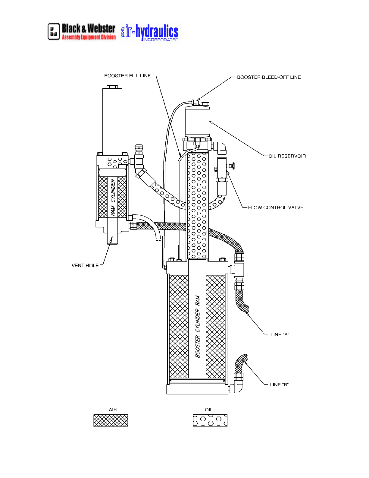
AIR & OIL FLOW FOR AIR-HYDRAULIC BOOSTER SYSTEMS
FOR MODEL NUMBERS B-250, B-300, B-400, and B-500
1. When the valve is energized, line “B” is filled with air, causing the booster piston and ram to rise.
2. As the booster ram enters the oil chamber, pushing the oil out, pressure is developed and
transferred to the ram cylinder. This pressure is maintained throughout the stroke.
3. Air from the downward stroke of the ram cylinder and the upward stroke of the booster cylinder
is exhausted through line “A” throughout the stroke.
4. The oil which is flowing through the speed control valve enters the ram cylinder and pushes the
ram down.
5. When the valve is de-energized, line “A” is filled with air causing the ram cylinder to move up
and the booster cylinder to move down.
6. The only function of the booster fill line is to replenish the oil in the event a leak occurs
somewhere in the system. The oil enters the chamber through the middle head of the booster
cylinder and a small hole in the top of the booster ram.
7. The only function of the booster bleed off line is to return oil back to the reservoir in the event oil
does leak by the seal in the booster.
8. The bleed hole which is located near the end of the ram cylinder is for the bleeding of oil in the
event any leakage occurs in the seals.
5
Page 6
545 Hupp Ave. P.O. Box 831, Jackson, MI 49203
Phone: (517- 787-9444 Fax: (517) 787-7585
Email: [email protected]
Black & Webster Products Division
6
Page 7
545 Hupp Ave. P.O. Box 831, Jackson, MI 49203
Phone: (517- 787-9444 Fax: (517) 787-7585
Email: [email protected]
Black & Webster Products Division
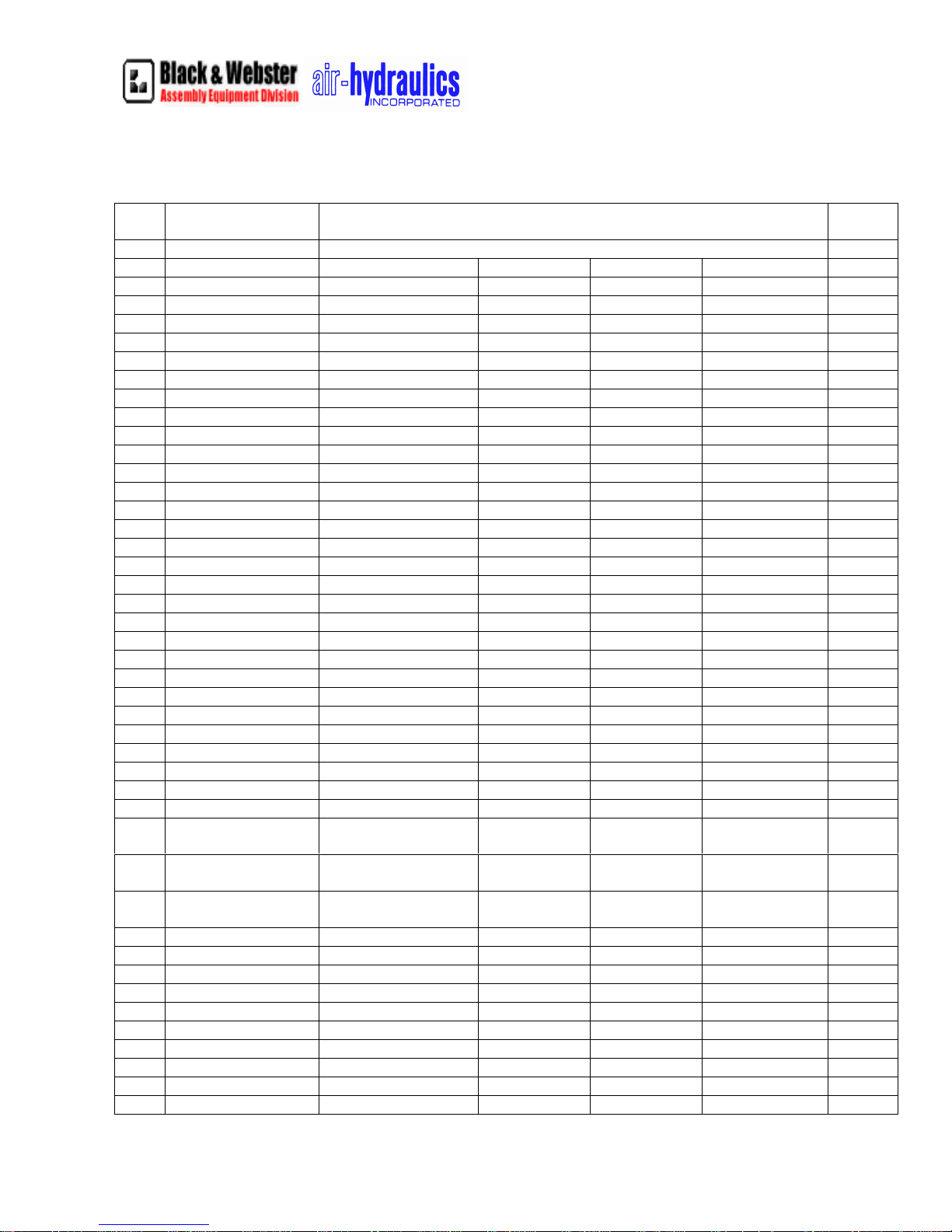
Air-Hydraulic Booster System Parts List
Det.
#
B-250 B-300 B-400 B-500
3 Air Cyl. Piston Seal 568-433 568-443 568-443 568-452 1
4 Air Cyl. Body C2-04 C3-04 C4-04 C5-04 1
5 Air. Cyl. Top Head C2-05 C3-05 C4-05 C5-05 1
5A Hyd. Cyl. Body C3-05A C4-05A C5-05A 1
5B Hyd. Cyl. Top Head C2-05B C3-4-05B C5-05B 1
6 High Press Hose H-10-21-ASSY H-C3-4-ASSY H-C3-4-ASSY H-C500-31 1
7 Air Cyl. Bottom Hyd. C2-07 C3-4-07 C3-4-07 C5-07 1
8 Air Cyl. Piston C2-08 C3-4-08 C3-4-08 C5-08 1
9 Air Cyl. Ram C2-09 C3-09 C4-09 C5-09 1
10 Air Cyl. Tie Rods C2-10 C3-10 C4-10 C5-10 4
11 Ram Cyl. Bot. Head. C2-11 C3-4-11 C3-4-11 C5-11 1
12 Ram C2-12 C3-12 C4-12 C5-12 1
12a Ram Cyl. Piston C2-12A C3-4-12 C3-4-12 C5-12A 1
13 Ram Cyl. Body C2-13 C3-13 C4-13 C5-13 1
14 Ram Cyl. Top Head C2-14 C3-14 C3-4-14 C5-14 1
15 Ram Cyl. Tie Rods C2-15 C3-15 C4-15 C5-15 4
16 Hyd. Cyl. Tie Rods C2-16 C3-16 C4-16 C5-16 4
17 Air Cyl. Ram Seal 1870-2125 1870-1875 1870-3250 3
18 Ram Seal 1250-1000 1870-1500 1870-1500 1870-2750 1
19 Static Seal 568-115 568-214 568-214 568-218 2
20 Ram Piston Seal 1870-2625 1870-3625 1870-3625 2500-5250 2
21 Flex-loc Nut-Ram FN-0.875-14 FN-1.250-12 FN-1.250-12 FN-1.500-12 1
22 Ram Top Head Seal 1250-0750 1250-1000 1250-1000 1250-1250 1
23 Down Stop Plate C2-23 C3-4-23 C3-4-23 C5-23 1
24 Oil Reservoir RESERVOIR RESERVOIR RESERVOIR RESERVOIR 1
25 Hex Nuts-Tie Rods 36509 36509 36509 36515 12
26 Down Stop Nut C2-A28-50-26 C3-4-26 C3-4-26 C5-26 1
27 Down Stop Lock Nut 36513 36368 36368 36372 1
28 Speed Cont. Valve PPC-FCV-F35BK PPC-FCV-
29 Air Cyl. Gaskets V-6.000X6.500 V-
30 Ram Cyl. Gaskets V-3.000X3.500 V-
30a Ram Cyl. Ring Seal 2-149 568-240 568-240 568-254 1
30b Ram Cyl. Seal - B/U - 8-240 8-240 - 2
32 Hyd. Cyl. Seal 2-142 2-149 2-149 568-242 2
32a Hyd. Cyl. Seal - B/U - 8-149 8-149 8-242 2
32b Hyd. Cyl. Gasket D -2.500x3.00 D - 3.00x3.500 D - 3.00x3.500 - 2
33 Low Press. Hose 10LOLA 10LOLA 10LOLA 12LOLA 1
34 Guard Tube C2-34 C3-4-5-34 C3-4-5-34 C3-4-5-34 1
36 Reservoir Bracket C250-100 C250-100 C250-100 C250-100 1
Part Name PART NUMBERS Quan.
PPC-FCV-
F35BK
8.000X8.5000 V-8.000X8.5000 V-12.000X12.500
4.000X4.500 V-4.000X4.500
F35BK
PPC-FCV-
EFL40S
V-5.750X6.500
and 568-257
1
2
1
7
Page 8
545 Hupp Ave. P.O. Box 831, Jackson, MI 49203
Phone: (517- 787-9444 Fax: (517) 787-7585
Email: [email protected]
Black & Webster Products Division
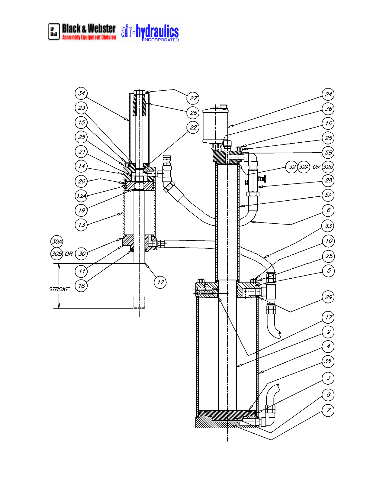
Air-Hydraulics’ Booster System Parts
8
Page 9
Black & Webster Products Division
545 Hupp Ave. P.O. Box 831, Jackson, MI 49203
Phone: (517- 787-9444 Fax: (517) 787-7585
Email: [email protected]
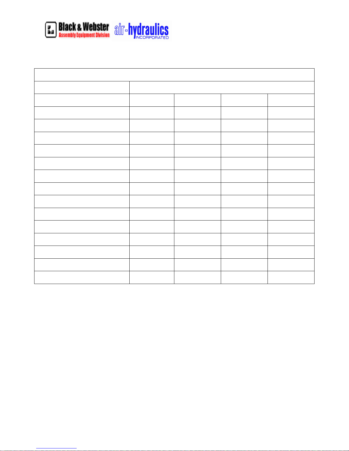
GENERAL SPECIFICATIONS
Model No.
Tons at 100 PSI Air
Power Ratio (No. x air line PSI= Approx.
Force
Max. Ram Stroke (adjustable 2” shorter)
Cubic in. of Pressurized Air Per Full
Stroke Cycle
Air Cyl. Port Pipe Size - 4 Way Control
Valve
Return Force at 100 PSI
AIR CYLINDER
Inside Diameter 6 8 8 12
Rod Diameter 2-1/8 2-1/2 1-7/8 3-1/4
Stroke 10-1/4 15-5/8 18-1/2 20-3/16
RAM CYLINDER
Inside Diameter 3 4 4 5-3/4
B-250 B-300 B-400 B-500
2-1/2 5-1/2 10 15
50 110 200 300
5-3/16 6 4 6
577 1562 1865 4521
1/2 3/4 3/4 3/4
628 1080 1080 2003
Top Rod Diameter .750 1.000 1.000 1.250
Bottom Rod Diameter 1.00 1.500 1.500 2.750
NET WEIGHT
350 500 650 800
9
Page 10

Air-Hydraulics Booster Systems
Model’s B-250, B-300, B-400 and B-500
Preventative Maintenance and Trouble Shooting
1. Before any preventative maintenance is performed, turn off air supplies to system and
block up ram, following OSHA and local Lock out/Tag out procedures.
2. Keep the oiler/lubricator filled with Mobil DTE grade 24 or equivalent. Lubricator is
adjusted at the factory, but it should be reviewed monthly. The larger the cylinder
area, the more lubrication the press needs. Use the following chart for a general rule of
thumb.
Model No. Cycles per drop
B-250 10
B-300 7
B-400 7
B-500 5
If the ram is chattering, then you may need to increase lubrication. If you are getting
too much oil out of the exhaust air muffler, then you may need to turn down the
lubricator.
3. Review and inspect air filter, it should be removed and replaced once the filter element
turns tan or a brownish color.
4. Oil should be changed in the booster if the color is dark brown or after 5 years, which
ever comes first
5. Oil Reservoir should be check daily and filled to proper level.
6. Check press for oil leakage at the following indicators;
a. Bleed off hole or ram vent hole; a small 1/8” diameter hole located in the
front of the machine, at the ram guide. If oil or air is coming out of this
hole, this indicates that the seal need replacing. Note, this hole can not be
blocked or covered.
b. Booster Bleed-off Line; the 1/8” tube located in the back of the machine,
coming from the side of the middle of the booster, going to the TOP of the
oil reservoir. If there is oil in this line, this is an indication that the seals
need to be replaced.
c. Air muffler; if an excessive amount of oil is coming out of the air muffler;
this too is an indicator that seals need to be replaced or the lubricator needs
to be turned down.
d. Oil Reservoir; if you have to fill reservoir frequently, then there is a
possibility that seals could be worn and need replacing.
10
Page 11

7. Check all safety devices DAILY, for proper operation. If they are not functioning
properly, DO NOT OPERATE THE SYSTEM!
8. Frequently asked questions;
QUESTION: Why is hydraulic oil is coming out of the reservoir?
ANSWER: There are excessive amounts of air in top side of the ram cylinder
or in the top of the oil side of the booster. With the ram in the home position,
bleed oil side of system by unscrewing the two caps until all air has been
exhausted. Do not remove caps. See page 4 of manual sent with machine. This
could be caused by short cycling the system, preventing the ram from returning
to the home position. Or it may be caused by ram drift down; over time the
reservoir may appear to be empty, refilling it at this time will overfill the
system. If this doe not solve the problem, then seals are the problem. They are
either installed wrong or need replacing.
QUESTION: Hydraulic oil levels in the reservoir go up and down when press
is cycled.
ANSWER: There is a small amount air trapped in the hydraulic system. You
need to bleed the air out of the system, see page 4 of manual
QUESTION: After several cycles, I lose ram pressure or force.
ANSWER: The air volume to the system is not adequate or the filter(s) needs
replacing. Make sure you have a minimum of 3/4" air line to the system from
the drop. Check air pressure drop at inlet when press cycles; it should not drop
below 75 psi. Increase air volume to system.
QUESTION: Hydraulic oil is in the vent tube, the tube that comes out of "top"
of the reservoir and goes down into the "side" of the air cylinder top head
(middle of the booster); is that normal?
ANSWER: No, this indicates that the hydraulic seals in the air cylinder top
head are worn and eroded and need to be replaced. Make sure new seals are
installed properly. If seals are installed upside down or are damaged while
being installed, the problem will still remain.
QUESTION: I'm not sure, but I think air is getting into my hydraulic
system. How can I test this?
ANSWER: There are two places which air can by pass seals and enter into the
hydraulic system; through the booster or the ram. You can test the ram cylinder
in the following way: Make sure ram is in the retracting mode. Remove the
ram guide from the ram, exposing the 1/8" by- pass hole, located on the front
side of the ram. Place soapy water over the 1/8'' hole (similar to finding leaks
in a gas line). If it blows a bubble, air is "by passing" the seal and entering the
hydraulic system. The bottom seal of the ram cylinder needs replacing. When
assembling the ram guide, be sure the slit is in position over the hole, therefore
11
Page 12

not plugging it. You can test the booster again by applying air to the booster
through the ram retraction side. Remove the 1/4" tube going to the top of the
reservoir and coming out of the side (not the top) of the booster cylinder (air
side) top cap. Put the tube in jar of water, if it blows a bubble, the bottom seal
in the booster needs replacing.
QUESTION: During the first cycle of the press, after being shut down over the
weekend, oil will erupt from the reservoir top. What is causing that?
ANSWER: To prevent the eventual drifting down or closing, when the air
supply to this press is turned OFF, the die set or tooling should be blocked in
an OPEN position due to weight of tooling attached to the ram of this press.
This will keep the closed hydraulic circuit of this press from becoming
imbalanced, misleading the circuit to siphon oil from reservoir top
unnecessarily, which could damage the press.
QUESTION: After several cycles, I get oil bubbling out of the oil reservoir and
there is air coming out of the vent hole of the ram.
ANSWER: The problem is in your Ram Cylinder. The "U" Cup seals are
installed incorrectly, damaged or worn, and/or the "O"-rings (located where the
piston attaches to the ram) are in need of repair, replacement or are missing.
Air is coming from the rod/bottom of the cylinder, going up through the button
"U" seal on the piston, or through the "O"-rings; allowing air to enter into the
closed hydraulic system, therefore, being relieved through the reservoir. If the
oil is bubbling to the point of over flowing, then the seals/"O"-rings are
extremely damaged, or the seals are installed backwards or are missing.
QUESTION: There is air building up in my reservoir. I can feel it when I put
my finger over the hole, but it is NOT bubbling up through the oil in the
reservoir.
ANSWER: The problem may be in the booster. You can further test this by
applying air to the booster through the ram retraction side (top port). Remove
the 1/4" tube going to the top of the reservoir and coming out of the side (not
the top) of the booster cylinder (air side) top cap. Put the tube in jar of water, if
it blows a bubble, the bottom seal in the booster needs replacing or was
installed incorrectly.
12
 Loading...