


BlackTrax Wiki
BlackTrax Wiki
1 of 298
5/14/2019
A Complete BlackTrax User Wiki

About Introduction
BlackTrax Wiki
2 of 298
5/14/2019
This wiki provides instructions for the installation, configuration and operation of the BlackTrax system.
This version is current as of May 2019.
© CAST Group of Companies Inc., 2002-2019 All rights reserved. BlackTrax, WYSIWYG, CAST Software,
and Autofocus are trademarks of the CAST Group of Companies Incorporated. All other trademarks and
logos are the property of their respective owners. Depending on your product/version, CAST incorporates
source code or libraries which are licensed to CAST and copyright protected. For more information, go to
http://cast-soft.com/third-party-libraries/.
A BlackTrax License will authorize the use of the BlackTrax system for a restricted number of output
connections based on the type of License that was purchased. For more information, go to Licensing.

About this Manual
BlackTrax Wiki
3 of 298
5/14/2019
Table of contents:
1 Introduction :
2 Text Conventions :

Text Conventions
BlackTrax Wiki
4 of 298
5/14/2019
The following text conventions are used in this wiki:
Instructions titles appear in Bold and Orange. For example, "To view a BTCamera’s video feed
in the visible spectrum"
Menus and menu commands appear in Bold and Navy. For example, “To open the window if
closed, go to the View menu and click Cameras.”
User interface elements such as buttons, tools, shortcuts, and dialog boxes appear in Italics and
Medium Blue. For example, “To close the project, click Yes.”
Keyboard keys are indicated in CAPITALS AND BLUE. For example, “To call up the save menu, enter
in the command CTRL+SHIFT+B.”
References to manuals appear in Italics Underlined in Blue. For example, “For an in depth
understanding on BTWYSIWYG and its capabilities, please refer to the WYSIWYG Reference Guide.”
Instructions to direct you to different features of the BTSystem or areas in the physical Space are
indicated by being Green and Underlined. For Example “In the Physical Space, take the BTBeacon.”

BlackTrax System Overview
BlackTrax Wiki
5 of 298
5/14/2019
1 BTSensor Installation :
1.1 Environment Considerations for BTSensor Installation :
1.2 Installing a BTSensor Lens :
1.3 BTSensor Placement and Orientation :
2 BTSystem Hardware Configuration :
2.1 BTSystem Configuration :
2.2 Optional Equipment Configuration :
3 BTSystem Components :
3.1 Standard System Components :
3.2 BTServer :
3.3 TimeKeeper :
3.4 BTRouter :
3.5 Ferrite Filter :
3.6 eSync 2 Controller :
3.7 BTSensors :
3.7.1 SLIM 13E :
3.7.2 PRIME 41 :
3.8 BTBeacon :
3.9 BT Smart Charger :
3.10 Calibration Kit :
3.10.1 Calibration Kit functions :
3.10.2 Wand Head :
3.10.3 Triangular Wand Holder :
3.10.4 Telescopic Wand Handle :
3.10.5 Ground Plane :
3.10.6 Hybrid Power Supply Unit (HPSU) :
3.10.7 Lighting Wand :
3.10.8 BTCalibration Kit Case :
3.11 Stringer :
3.12 Discontinued :
3.12.1 eSync Controller :
3.12.2 S250e Slim :
3.12.3 Power Supply Unit (PSU) :
3.12.4 BTServer (Legacy) :
3.12.5 TimeKeeper (Legacy) :
4 General System Information :
4.1 BTSystem Information Flow and Connections :
4.2 BTX Dongle :
4.3 Saved System Data :
4.4 FCC Information :
5 Not Included Mandatory Components :
5.1 Category 6 Ethernet Cabling :
5.2 Power Over Ethernet Gigabit Switch for BTSensors :
6 Optional Components :
6.1 DMX/Ethernet Node for Tracking with Moving Lights :

6.1.1 Compatible DMX/Ethernet nodes :
BlackTrax Wiki
6 of 298
5/14/2019
6.1.2 Luminex Node Settings :
6.1.3 Common ArtGate Node Setup Guide :
7 System Procedures :
7.1 Licensing :
7.2 Charging BTBeacons :
7.3 Replacing a BTBeacon's Lithium-Ion Battery :
7.4 Installing Third Party Software :
7.5 Server Failover :

BTSensor Installation
BlackTrax Wiki
7 of 298
5/14/2019
Table of contents:
Environment Considerations for BTSensor Installation
Installing a BTSensor Lens
BTSensor Placement and Orientation

Environment Considerations for
BlackTrax Wiki
8 of 298
5/14/2019
BTSensor Installation
The environment of the Space has a great impact on the capacity of BlackTrax to function as intended.
When you install the BTSystem, always remember the following precautions to limit interference and
make the ideal tracking environment.
Infrared interference: External infrared sources and reflections may cause interference with
BTSensors. For best results, ensure the venue is free from sunlight, lights which emit infrared
spectrum, infrared based devices, fire, and highly reflective materials. For infrared sources and
reflections which cannot be removed from the venue, there are provisions within the software to
mask out the affected areas of the BTSensor's field of view.
Note: Infrared interference is more critical during the BTSensor calibration than during
tracking operation. Since the BTSystem looks for a unique signal during tracking, there is
some tolerance for other infrared sources.
Reflective surfaces: Reflective materials that are present in a venue might reflect and mimic a
BTBeacon’s unique LED pulse, creating errors with tracking. Complex objects inside the tracking
area must be covered to block reflections. Reflective objects outside the tracking area can be
blocked out.
Cabling: Ethernet connected BTSensors are subject to the limitation of Ethernet communication
standards. The total Ethernet connection between any component to the BTServer can not be
longer than 91.44m for BlackTrax to function correctly. This range may be extended with a PoE
switch to link cables together.
Sensor stability: Ensure that the location where you choose to install BTSensors is stable, sturdy
and always stationary. Any movement of a BlackTrax sensor will require recalibration of the entire
sensor system.
Example: If a BTSensor is hung on a truss system which sways, the accuracy and
performance of the BTSystem will be affected. If the sway is small, you can decrease
accuracy in the system and may be able to track with lesser accuracy.
Sensor blocking: Ensure that BTSensors have an unimpeded view of the intended tracking area.
Multiple BTSensors need to see the same area at the same time for tracking to occur. Care should
be taken to ensure temporary objects do not obscure tracking.

Installing a BTSensor Lens
BlackTrax Wiki
9 of 298
5/14/2019
To install a BTSensor lens
Note: Only used on s250e and Slim 13E sensors.
Screw the lens onto the BTSensor with the included plastic lens tensioner between the M12 lens1.
adapter and the lens itself. Tighten until proper focus is achieved.
Once you achieve the desired focus, hold the lens in place while you tighten down the lens2.
tensioner.
Note: The s250e comes with a spring for the lens instead of a tensioner. No tightening is required for
this lens.

BTSensor Placement and Orientation
BlackTrax Wiki
10 of 298
5/14/2019
In order for tracking to function correctly, multiple BTSensors must be arranged to have overlapping
fields of view of the Space. A BTSensor's field of view is the part of the Space that is visible through the
BTSensor while the BTSensor is in a fixed position and orientation.
Attention: Sensors must not be installed closer than 1m apart to help ensure optimal sensor calibration.
Good sensor placement and orientation are absolutely critical to proper operation of the BTSystem!

BTSystem Hardware Configuration
BlackTrax Wiki
11 of 298
5/14/2019
Table of contents:
BTSystem Configuration
Optional Equipment Configuration
BTSystem Configuration
BlackTrax Wiki
12 of 298
5/14/2019
System Configuration Overview
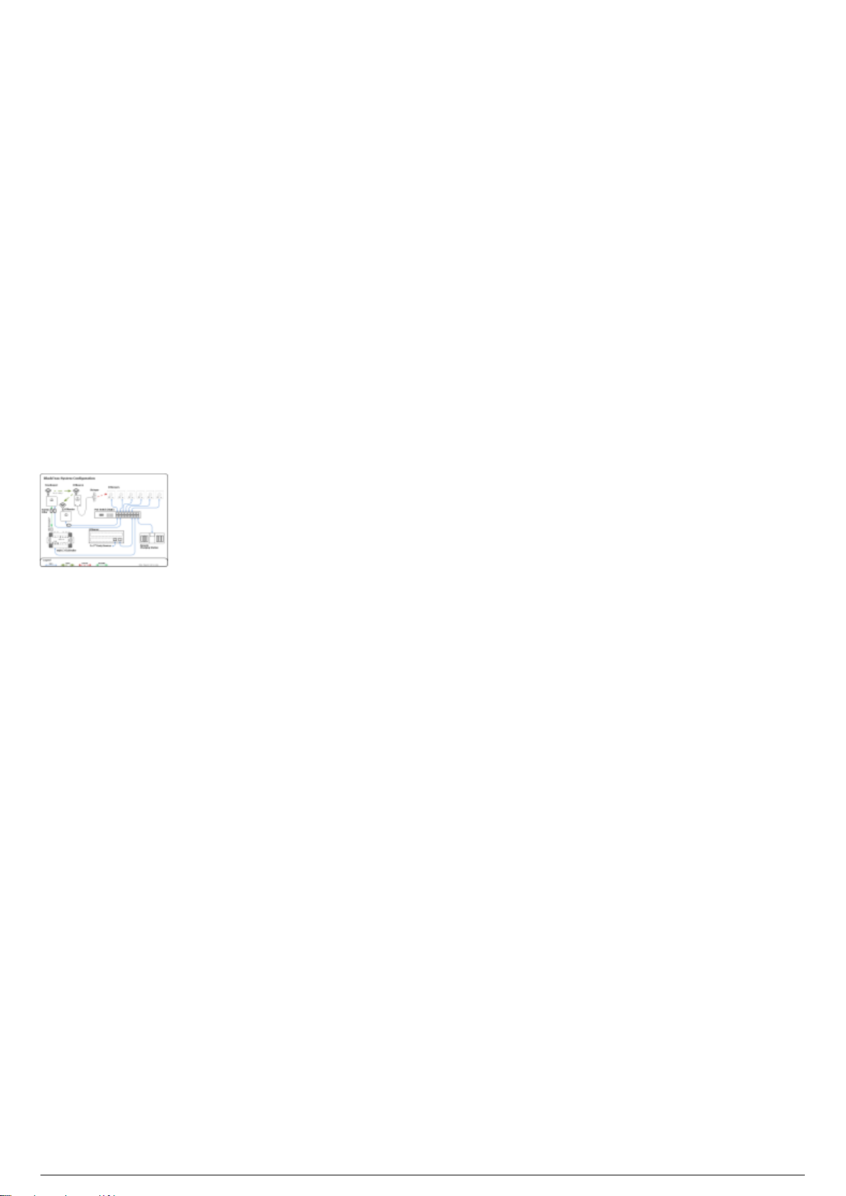
Hardware modules that connect directly to the BTServer should be located in the same location outside
of the tracking area. BTSensors must be positioned where they will not be disturbed and have the best
unblocked view of the tracking area. TimeKeeper, BTRouter and eSync 2 Controller can be positioned
closer to the tracking space.
The following diagram outlines a typical hardware configuration and demonstrates how all BlackTrax
hardware modules are connected together.
Attention: The Timekeeper and BTRouter Ethernet port are designed only to connect to a commercially
available Power over Ethernet (PoE) network switch. The TimeKeeper and BTRouter are not designed to
be a peripheral device to a Class B personal computer. As such, the Ethernet port shall not be connected
to a Class B personal computer in any operating configuration.
BlackTrax System Configuration Diagram
Optional Equipment Configuration
BlackTrax Wiki
13 of 298
5/14/2019
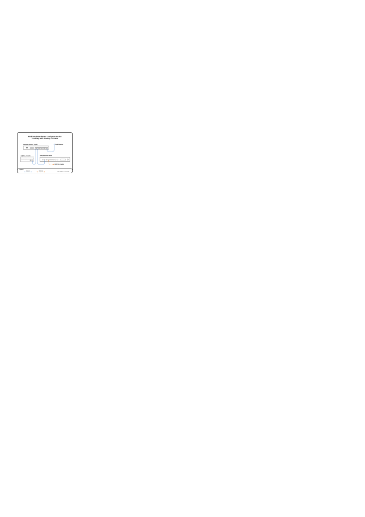
Optional Equipment Overview
Depending on your tracking needs, additional components must be connected with the BTSystem. The
following outlines how to connect this optional equipment with the BTSystem.
Tracking with Moving Light Fixtures Diagram

BTSystem Components
BlackTrax Wiki
14 of 298
5/14/2019
Table of contents:
Standard System Components
BTServer
TimeKeeper
BTRouter
Ferrite Filter
eSync 2 Controller
BTSensors
SLIM 13E
PRIME 41
BTBeacon
BT Smart Charger
Calibration Kit
Calibration Kit functions
Wand Head
Triangular Wand Holder
Telescopic Wand Handle
Ground Plane
Hybrid Power Supply Unit (HPSU)
Lighting Wand
BTCalibration Kit Case
Stringer
Discontinued
eSync Controller
S250e Slim
Power Supply Unit (PSU)
BTServer (Legacy)
TimeKeeper (Legacy)
Standard System Modules
BlackTrax Wiki
15 of 298
5/14/2019
List of Standard System Components
Note: The quantity of BTSensors, BTBeacons, BTSmart Chargers, and Stringers delivered with a
BTSystem are dependent on each user’s needs and on the individual sale.
(1) BTServer (pre-installed software below)
Hardware secured inside the server
BTX Dongle
Motive Dongle
Pre-installed software
BTWYSIWYG
Motive for BlackTrax
BlackTrax Software Suite
Device Manager
(1) BTRouter
(1) TimeKeeper
Ferrite filters
(1) eSync 2 Controller*
BNC/RCA Adapter
BTSensors
BTBeacons
Stringers
BTSmart Charger
(1) BTCalibration Kit
(1) BTCalibration Wand Head
(1) BTCalibration Triangular Wand Holder
(1) BTCalibration Telescopic Wand Handle
(1) BTCalibration Ground Plane
(1) BTCalibration Hybrid Power Supply Unit
(1) BTLighting Calibration Wand
(1) Carrying case
Attention: *The original eSync Controller is discontinued.
Not Included Mandatory Components
Category 6 Ethernet cable
Power over Ethernet (PoE) gigabit Switch
Optional Components
DMX/Ethernet Node (for tracking with moving lights)
Additional Power over Ethernet (PoE) gigabit Switches

BTServer
BlackTrax Wiki
16 of 298
5/14/2019
BTServer 2.0 (Rev 5)
Product ID
Model: BTServer 2.0 (Rev 5)
Physical Characteristics
Width: 48 cm (19")
Height: 9 cm (3.5")
Depth: 48.5 cm (19")
Weight: 15.2 kg (33.5 lb.)
Operating Temperature
0°C - 40°C
Technical Specifications
BTServer 2.0 (Rev 5):
(2x) Inter Xeon Silver 4110 @ 2.1GHz (3.00 GHz Turbo, 2400 MHz, 11M L3 Cache, 8 Core, 85W)
(2x) 2.5" 480GB SSD SATA in RAID1 on LSI MegaRAID SAS 9341-4i
32GB (8x4GB) RAM (DDR4, ECC, 2666 MHz)
Nvidia GeForce GTX1060 with 6GB GDDR5
100-240VAC, 800W redundant power supply with IEC
(2x) Intel I350 Quad-Port Gigabit Ethernet Controller (1 dedicated, 1 definable)
Windows 10 IoT Enterprise LTSB 2016
Default User Login
User name: btuser
Note: There is no password associated with the default user account for the BTServer
Default Network Address (Main)

Default Network Address (Backup)
BlackTrax Wiki
17 of 298
5/14/2019
Note:
The BTServer is built with 2 Network Interface Cards (NIC) with 4 ports on each card, and the
functions are: (see BlackTrax detailed system diagram)
Port 1: BTNet (PoE Switch - Tracking, BTSensors, BT Smart Chargers)
Port 2: RTTrPL and Lighting Input (Network Switch - Lighting)
Port 3: RTTrPM (Network Switch - 3rd Party)
Port 4: BTLink (links to BTServers)
Port 5-8: (User Defined)
Lighting Input and RTTrPL are combined into the RTTrPL port.
BTLink is the network connection link to the other BTServers.
Attention: Windows Remote Desktop Connection should not be used with a BlackTrax system. Security
measures on the BTX dongle installed in the BTServer will prevent it from working. Users should use
TeamViewer or VNC if remote access to a BTServer is required.
TimeKeeper
BlackTrax Wiki
18 of 298
5/14/2019
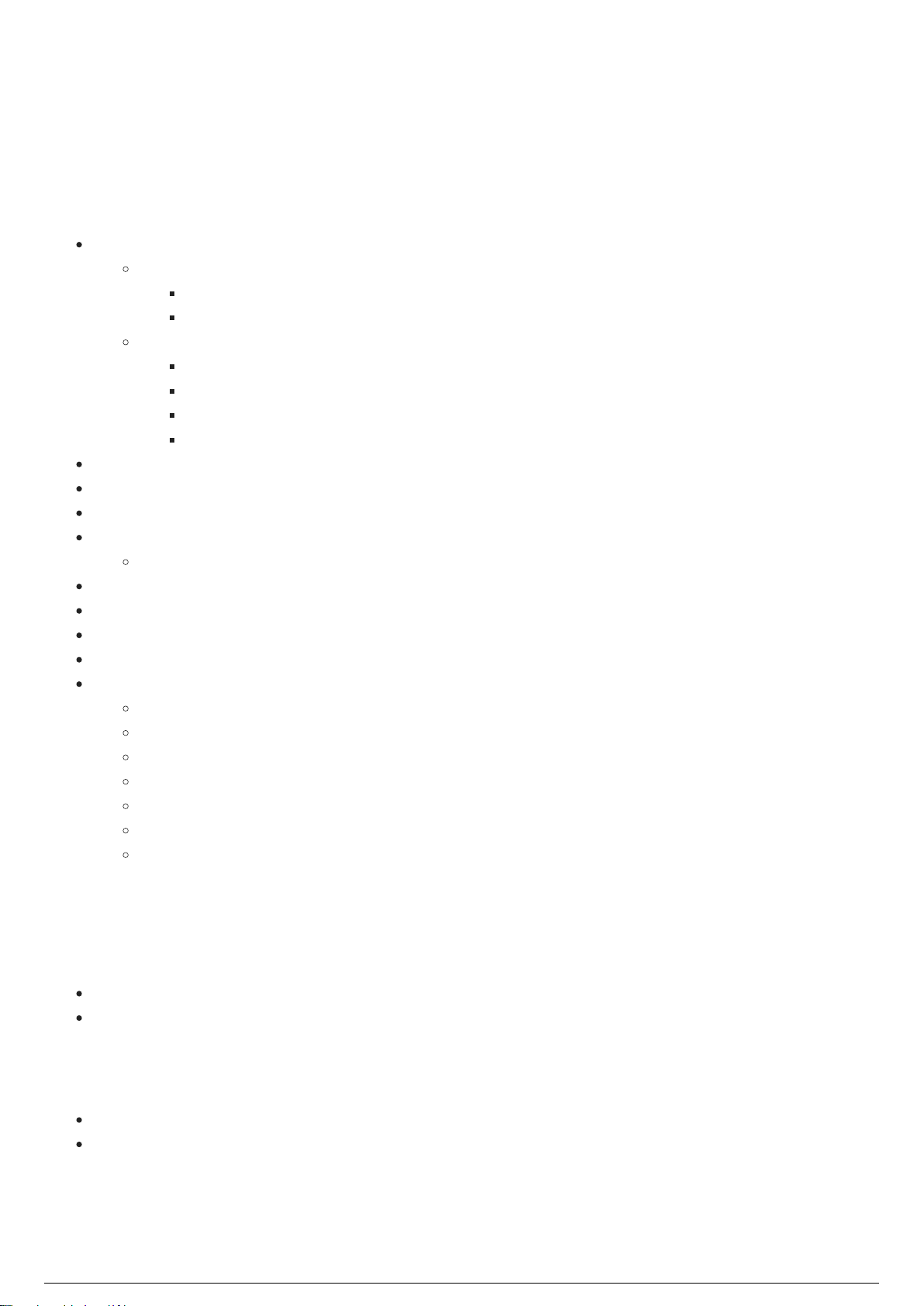
TimeKeeper (Rev J) Diagram
Product ID
FCC ID: RKT-BTTKV01
IC: 10858A-BTTKV01
Model number: BTTKV01
Physical Characteristics
Width: 6.46 cm (2.545")
Height: 7.50 cm (2.951")
Depth: 2.50 cm (0.968")
Weight: 86.64 g (3.056 oz)
Operating Temperature
0°C to +40°C (32°F to 104°F)
Input/Output & Power
Data: Ethernet, Radio 2.4(GHz) 10Hz
Power: 48VDC/15.6W from PoeE Network Switch via Ethernet port (No input power via USB port)
Status LEDs
Note: The Ethernet status lights on the TimeKeeper are not enabled while the TimeKeeper is in use.

TimeKeeper Functions
BlackTrax Wiki
19 of 298
5/14/2019
The TimeKeeper is a single wireless access point that uses a proprietary radio system running on the 2.4
Ghz frequencey to send data to all BTBeacons. Data sent includes a signal used to synchronize the
BTBeacons with the BTSensors and configuration commands sent to the eSync Controller via a BNC
cable.
TimeKeeper Transmitter Characteristics

BTRouter
BlackTrax Wiki
20 of 298
5/14/2019
BTRouter Diagram
Product ID
FCC ID: RKT-BTTKV01
IC: 10858A-BTTKV01
Model number BTTKV01
Physical Characteristics
Width: 5.7 cm (2.245")
Height: 7.11 cm (2.8")
Depth: 2.57 cm (1.013")
Weight: 125 g (4.41 oz)
Operating Temperature
0°C to +40°C (32°F to 104°F)
Input/Output & Power
Data: Ethernet, Radio 2.4(GHz) 10Hz
Power: 48VDC/15.6W from PoE Network Switch via Ethernet port (No input power via USB port)
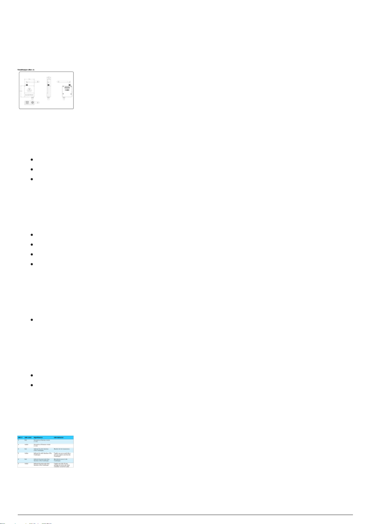
Status LEDs

BTRouter Functions
BlackTrax Wiki
21 of 298
5/14/2019
The BTRouter is a single wireless access point that uses a proprietary radio system running on 2.4 Ghz
frequency to receive data from all BTBeacons. Data received includes BTBeacon button presses, battery
status, configuration details as well as inertial measurement unit (IMU) data. IMU data can be used to
calculate the BTBeacon’s orientation.
Note: Upon delivery of a new BTSystem shipment, the IMU on most of the Beacons included are disabled
by default, and the IMU of the Beacon with ID 1 will be switched on by default to help with Fixture
Calibration.
BTRouter Transmitter Characteristics

Ferrite Filter
BlackTrax Wiki
22 of 298
5/14/2019
Ferrite Filter Diagram
Product ID
Manufacturer: API
Model number: BF1835
Physical Characteristics
Width: 1.8 cm (0.709”)
Height: 1.96 cm (0.776”)
Depth: 3.48 cm (1.378”)
Center diameter: 0.89 cm (0.354”)
Weight: 15 g (.53 oz)
Operating temperature: 0°C to +40°C (32°F to 104°F)
Impedance: 172 Ohm
Ferrite Function
The ferrite filter is a cylindrical clamp fastened over cables to conform with regulatory standards. A
ferrite filter must be clamped over any cables connected to the TimeKeeper and BTRouter. Ferrite filters
should be fastened on any connected cables as close to the respective device as possible.

eSync 2 Controller
BlackTrax Wiki
23 of 298
5/14/2019
eSync 2 Controller Diagram
Physical Characteristics
Width: 13.89 cm (5.47”)
Height: 4.09 cm (1.61”)
Depth: 9.25 cm (3.64”)
Weight: 368.54 g (13 oz)
Operating temperature: 0°C to +40°C (32°F to 104°F)
Input/Output & Power
PoE: IEEE 802.3af-2003
Adapter: 12V @ 0.6A power supply
Data: Ethernet
Status LEDs
Per port activity status
Master time
External lock
Ethernet link status
Ethernet activity
eSync 2 Controller Functions
The eSync 2 Controller synchronizes BTSensors so that the shutters of BTSensors open and close
simultaneously and in synchronization with the pulsing of LED Stringers attached to BTBeacons.
eSync 2 Controller Connection to the TimeKeeper
The eSync 2 Controller connects to the TimeKeeper over RCA cable. A BNC/RCA adapter is used to plug
the RCA into input 3 of the eSync 2 Controller.

BTSensors
BlackTrax Wiki
24 of 298
5/14/2019
Table of contents:
SLIM 13E
PRIME 41

SLIM 13E
BlackTrax Wiki
25 of 298
5/14/2019
SLIM 13E Diagram
Product ID
Model number: CAM-CAM-S13
Physical Characteristics
Mounting: 0.635 cm (1/4”)-20 tripod thread
Operating temperature: 0°C to +51°C (32°F to 123.8°F)
Case: Aluminum and Polycarbonate
Width: 6.86 cm (2.7”)
Height: 6.86 cm (2.7”)
Depth: 2.3 cm (0.9”)
Weight: 320 g (11.29 oz)
Lens & Filter
Stock lens: 5.5 mm F#1.8 (wide band AR coated)
Horizontal FOV: 56°
Vertical FOV: 46°
Optional Lens: 8.0 mm F#1.8 (wide band AR coated)
Horizontal FOV: 42°
Vertical FOV: 34°
Optional Lens: 3.5 mm F#1.8 (wide band AR coated)
Horizontal FOV: 82°
Vertical FOV: 70°
Adjustable focus with wave spring assist
850nm band-pass filter
850nm (Infrared) / 700nm (Visible) Filter Switcher
Image Sensor
Resolution: 1280 × 1024
Frame Rate: 30–240 FPS (100 FPS average usage)

Accuracy: Sub-millimeter
BlackTrax Wiki
26 of 298
5/14/2019
Latency: 4.2 ms
Shutter type: global
Shutter speed:
Default: 0.5 ms (500 µs)
Minimum: 0.01 ms (10 µs)
Maximum: 3.9 ms (3,900 µs) at 240 FPS
Input/Output & Power
Data: Ethernet
Synchronization: Ethernet
Power: (PoE) 8.0 watts
Sensor Status
Front Light Status
The Slim Series sensors have a front LED status light to indicate their current state in relation to the
BTServer. The following table lists the default status light colors.
Back Light Status
The Slim Series sensors also have a status indicator on the back panel and indicates the state of the
sensor only. When updating the software on your BTServer, the sensor may need a firmware update in
order to communicate to the new version. Firmware updates are automatic when starting the connection
to the BTServer. If you revert back to an older version of the firmware as well. This process is automatic.
BTSensor Functions
BTSensors are used to view BTBeacon positions in the Space. A BTBeacon's position in 3 dimensions (X,
Y, and Z) can be determined when two or more BTSensors simultaneously have a direct line-of-sight to a
connected Stringer’s LED. This information is then sent to the BTServer.
Attention:
The switch must provide consistent power to every port simultaneously in order to power each
sensor.

Standard PoE switches must provide a full 15.4 watts to every port simultaneously.
BlackTrax Wiki
27 of 298
5/14/2019
Note that PoE Midspan devices or power injectors are not suitable for Ethernet camera systems.
PRIME 41
BlackTrax Wiki
28 of 298
5/14/2019
PRIME 41 Diagram
Product ID
Model number: CAM-CAM-P41
Physical Characteristics
Mounting: 0.635 cm (1/4")-20 tripod thread (x2)
Operating temperature: 0°C to +51°C (32°F to 123.8°F)
Case: Aluminum and Polycarbonate
Width: 12.6 cm (4.96”)
Height: 12.6 cm (4.96”)
Depth: 13.6 cm (5.34”)
Weight: 1.45 kg (3.2 lb)
Lens & Filter
Stock lens: 12 mm F#1.8 (wide band AR coated)
Horizontal FOV: 51°
Vertical FOV: 51°
Adjustable focus and f-stop
850nm band-pass filter
Image Sensor
Resolution: 2048 x 2048
Pixel Size: 5.5 µm x 5.5µm
Frame Rate: 30–180 FPS (adjustable)
Latency: 5.5ms
Shutter type: global
Shutter speed:
Default: 0.5 ms (500 µs)
Minimum: 0.01 ms (10 µs)
Maximum:

8.1ms (8100 µs) at 120 FPS
BlackTrax Wiki
29 of 298
5/14/2019
5.3 ms (5300 µs) at 180 FPS
Input/Output & Power
Data: GigE (1000BASE-T)
Synchronization: Ethernet
Power: PoE or PoE+¹
Attention:
The switch must provide consistent power to every port simultaneously in order to power each
sensor.
Standard PoE switches must provide a full 15.4 watts to every port simultaneously.
Note that PoE Midspan devices or power injectors are not suitable for Ethernet camera systems.

BTBeacon
BlackTrax Wiki
30 of 298
5/14/2019
BTBeacon Diagram
Product ID
FCC ID: RKT- BTBCV01
IC: 10858A- BTBCV01
Model: BTBCV01P
Physical Characteristics
Case: Plastic with Velcro strap attachments
Width: 4.94 cm (1.945”)
Height: 8.08 cm (3.18”)
Depth: 1.87 cm (.737”)
Weight: 70 g (2.5 oz)
Input/Output & Power
Data: USB, Radio 2.4 (GHz) 10Hz
Power: Rechargeable Lithium-ion Battery, charged by 5V USB
Watt hour: 4.44 Wh normal operation, 5.04 Wh while charging
Operating Temperature
0°C to +40°C (32°F to 104°F)
BTBeacon Status LEDs (During Operation)
Warning: If a BTBeacon experiences a charge error, there could be a potential issue with the Lithium-ion

battery. Discontinue use immediately. For more information about Lithium-ion battery safety see “Health
BlackTrax Wiki
31 of 298
5/14/2019
and Safety Information”. Alternately, no battery may be in the BTBeacon.
BTBeacon Status LEDs (During Boot
Loader Mode)
BTBeacon Functions
Each BTBeacon has three ports, each of which can power a single connected Stringer. When a Stringer is
connected to a BTBeacon’s LED port, the Stringer’s LED will emit infrared light in a unique pattern. These
infrared pulses create a unique ID used to identify BTBeacons. When the LED infrared pulse is seen by 2
or more BTSensors, the positional coordinates (XYZ) for the Stringer LED is calculated by the BTServer.
Position is based on the location of visible Stringer LEDs connected to a BTBeacon. Orientation data (roll,
pitch, yaw) is determined by an internal inertial measurement unit (IMU). The IMU also functions as a
backup for determining the BTBeacon's position. The IMU measures acceleration and rotation.
The BTBeacons have a red power and reset button, and two white auxiliary buttons. The auxiliary buttons
are used during fixture calibration.
The BTBeacon transmits the following data over radio to the BTRouter, which is relayed to the BTServer:
IMU data, button presses, battery status, configuration details, and Stringer IDs.
To enter the BTBeacon into Boot Loader Mode, turn the beacon off and hold A or B while inserting the
BTBeacon into the BTSmart Charger. This mode is used to update firmware.
BTBeacon Transmitter Characteristics
BTBeacon Charging Information
A BTBeacon’s rechargeable lithium-ion battery is not fully charged when shipped. Please read the
following instructions carefully:

Never charge BTBeacon near heat or flammable objects.
BlackTrax Wiki
32 of 298
5/14/2019
The temperature range which the BTBeacon can be charged is 0°C to 40°C (32°F to 104°F).
Charging outside the recommended temperature range may automatically be blocked by the
protection circuitry of the device.
Do not charge or use the BTBeacon if any damage has occurred to the device.
The temperature range over which the BTBeacon’s battery can operate is 0°C to 40°C (32°F to
104°F). Operation outside of this temperature range may damage the performance of the battery
or may reduce its life expectancy.
Battery performance will naturally decay over time. If a battery can not maintain charge for long
periods, even when it is being charged correctly, this may indicate it is time to replace the battery.
BTBeacon Battery Replacement
After a period of time the battery of the BTBeacon will naturally decay through normal use and require
replacement. Contract your BTE for details on replacing the BTBeacon battery.
Attention: Any unauthorized modification to the BTBeacon or its battery will invalidate any warranty
claim and may damage the device.

BT Smart Charger
BlackTrax Wiki
33 of 298
5/14/2019
BTSmart Charger Diagram
Size and Weight
Case: Steel
Width: 15.5 cm (6.1”)
Height: 8.47 cm (3.33”)
Depth: 36 cm (14.17”)
Weight: 2440 g (86.07 oz)
Input/Output & Power
Data: Ethernet, USB
Power: 20 Watt
Voltage range: 100V - 240V
Note: BTSmart Charger Rev 6 is built with a momentary contact type power button with the blue LED
that will light up only after the "boot up" is complete. To turn the device power off, press the power
button, then wait until the blue LED light turns off before you disconnect from the power source.
BTSmart Charger Functions
The BTSmart Charger is a device used to recharge the battery of a BTBeacon. BTBeacons are connected
to the BTSmart Charger using the BTBeacon’s USB port. While connected, the BTSystem can read the
status of the battery, regulate charging and maximize battery life. The BTSmart Charger can hold a
maximum of 6 BTBeacons at one time.
BTSmart Charger Configurations
The BTSmart Charger can be configured to either be horizontal and sit flat on a desk, or be vertical and
be mounted on a wall.

Horizontal Configuration Diagram
BlackTrax Wiki
34 of 298
5/14/2019

Calibration Kit
BlackTrax Wiki
35 of 298
5/14/2019
Table of contents:
Calibration Kit functions
Wand Head
Triangular Wand Holder
Telescopic Wand Handle
Ground Plane
Hybrid Power Supply Unit (HPSU)
Lighting Wand
BTCalibration Kit Case

Calibration Kit functions
BlackTrax Wiki
36 of 298
5/14/2019
BlackTrax Calibration Kit Functions
The Calibration Kit is used for calibrating the BTSensors and Lighting Fixtures position in the Space. The
function of each equipment in the Kit are:
The Wand Head is attached to the Wand Handle and connected to the Power Supply Unit.1.
When you move the Wand Head inside the Space, the BTSensors look for active LEDs located on2.
the Wand Head.
When multiple BTSensors see the LEDs on the Wand Head, the BTSystem is able to generate a3.
measurement point for BTSensor calibration.
BTSensors use the measurement point data to determine their position relative to each other.4.
The Ground Plane is connected to the Power Supply Unit and placed in the designated origin of the5.
Space.
The Ground Plane LEDs are used in the BlackTrax system to calculate the BTSensor positions6.
relative to the origin and the orientation of the Cartesian axes.
The Lighting Calibration Wand is used for fixture calibration.7.
The Lighting Calibration Wand can be attached to a BTBeacon instead of a Stringer to extend the8.
range of a BTBeacon LEDs. This is used to calibrate fixtures in areas that are difficult to reach.

Wand Head
BlackTrax Wiki
37 of 298
5/14/2019
Wand Head
Size and Weight
Width: 105.92 cm (41.7”)
Height: 26.92 cm (10.6”)
Depth: 2.03 cm (0.8”)
Weight: 715 g (25.22 oz)

Triangular Wand Holder
BlackTrax Wiki
38 of 298
5/14/2019
Triangular Wand Holder
Size and Weight
Length: 24 cm (9.45”)
Height: 17.5 cm (6.89”)
Width: 4.45 cm (1.75”)
Weight: 420g (14.82 oz)

Telescopic Wand Handle
BlackTrax Wiki
39 of 298
5/14/2019
Telescopic Wand Handle
Size and Weight
Length: 2.03 cm (0.8”)
Height: 149.86 cm (59”)
Width: 2.03 cm (0.8”)
Weight: 365 g (12.86 oz)

Ground Plane
BlackTrax Wiki
40 of 298
5/14/2019
Ground Plane
Size and Weight
Width: 76.96 cm (30.3”)
Length: 98.04 cm (38.6”)
Depth: 5.08 cm (2”)
Weight: 1905 g (67.2 oz)

Hybrid Power Supply Unit (HPSU)
BlackTrax Wiki
41 of 298
5/14/2019
Hybrid Power Supply Unit (HPSU)
Size and Weight
Width: 1.35 cm (0.5")
Height: 0.45 cm (0.2")
Depth: 1.1 cm (0.4")
Power Run Time
High: 1:00
Med: 2:45
Low: 3:15
Notes
Most applications (comparable to the previous PSU) use Medium, depending on the size of the1.
venue and how far the sensors are. You may try out low or high to conserve power or boost the IR.
A USB port is available where you can use to charge an external Beacon. 2.
An External Beacon can be charged approximately 90% if the HPSU is fully charged, and the
Beacon Battery is completely out of charge. This assumes no Stringers are attached to the
Beacon.
The HPSU can also be used to extend the life of a Beacon Battery if it is required to run past
its normal usage time. A Beacon with 1 Stringer has approximately 7.5 hours of additional
usage time. Beacons with either 2 or 3 Stringers attached have approximately 1 hour of
additional usage time.
Changing Internal Batteries in the HPSU
Attention: Please use an anti-static mat while being grounded.
Tool Required: *1/16 hex bit key.
To add batteries to the second pack

Side A Side B
BlackTrax Wiki
42 of 298
5/14/2019
Remove the 4 screws from Side A using the 1/16 hex bit.1.
Once the screws are removed, pull the panel away to reveal the interior of the HPSU.2.
Remove the board half way to expose the attachment for the power switch.3.
Carefully remove the power switch pin. Pull the pin straight upwards. 4.
Attention: AVOID MOVING THE PIN IN THE DIRECTION SHOWN IN THE PICTURE WITH
ARROWS (below).
Once the pin is removed, push the board back into the HPSU.5.
Turn the HPSU to Side B and remove the screws.6.
Remove the HPSU all the way to expose the second battery pack.7.
Add the batteries.8.
Tighten the straps. 9.
Reattach the power switch on Side A. Carefully pushing down the pin until it is locked in place.10.
Push the board back into the case, making sure not to pinch any wires on Side B.11.
Close Side A.12.
To change the pre installed HPSU batteries
Remove the 4 screws from Side A using the 1/16 hex bit.1.
Once the screws are removed, pull the panel away to reveal the interior of the HPSU. 2.
Note: HPSU board slides into the bottom slot of the interior.

Carefully pull the board out from the HPSU. You only need to remove the board half way to replace3.
BlackTrax Wiki
43 of 298
5/14/2019
the batteries.
Once you have replaced the batteries, tighten the Velco straps on the batteries.4.
Slowly and carefully push the board back into the HPSU.5.

Lighting Wand
BlackTrax Wiki
44 of 298
5/14/2019
Lighting Wand
Size and Weight
Size: 2 m (6.56’)
Weight: 235 g (8.29 oz)

BTCalibration Kit Case
BlackTrax Wiki
45 of 298
5/14/2019
BTCalibration Kit Case
Outside dimensions: 134.6 x 40.6 x 15.5 cm (53” x 16” x 6.12”)
Weight: (with foam lining only): 11.6 kg (25.57 lbs.)

Stringer
BlackTrax Wiki
46 of 298
5/14/2019
Stringer Diagram
Physical Characteristics
Cable length: 1.37 m (4.5') Custom sizes are available
Cable thickness: 2.9 mm (0.11")
LED Diffuser diameter: 7.93 mm (5/16")
Strain relief: 30 mm (1.18")
Male SMA Connector: 9 mm x 8 mm (0.35" x 0.32")
Male SMA Connector diagram
Stringer Functions
When a Stringer is connected to a BTBeacon LED port, the LED portion of a Stringer will pulse that
BTBeacon’s unique ID signal. The pulse is viewed by BTSensors, sent to the BTServer and used to
calculate the BTBeacon position in the Space.

Discontinued
BlackTrax Wiki
47 of 298
5/14/2019
Table of contents:
eSync Controller
S250e Slim
Power Supply Unit (PSU)
BTServer (Legacy)
TimeKeeper (Legacy)

eSync Controller
BlackTrax Wiki
48 of 298
5/14/2019
eSync Controller Diagram
Physical Characteristics
Width: 13.89 cm (5.47”)
Height: 4.09 cm (1.61”)
Depth: 9.25 cm (3.64”)
Weight: 368.54 g (13 oz)
Operating temperature: 0°C to +40°C (32°F to 104°F)
Input/Output & Power
PoE: IEEE 802.3af-2003
Adapter: 12V DC and 3 Amps
Data: Ethernet
Status LEDs
Per port activity status
Master time
External lock
Ethernet link status
Ethernet activity
eSync Controller Functions
The eSync Controller synchronizes BTSensors so that the shutters of BTSensors open and close
simultaneously and in synchronization with the pulsing of LED Stringers attached to BTBeacons.
eSync Controller Connection to the TimeKeeper
The eSync Controller connects to the TimeKeeper over RCA cable. The RCA cable is plugged into the RCA
port of the eSync Controller.

S250e Slim
BlackTrax Wiki
49 of 298
5/14/2019
S250e SLIM diagram
Product ID
Model Number: BT-S250-15
Physical Characteristics
Mounting: 0.635 cm (1/4”)-20 tripod thread
Operating temperature: 0°C to +51°C (32°F to 123.8°F)
Case: Aluminum and Polycarbonate
Width: 8.1 cm (3.19”)
Height: 8. cm (3.16”)
Depth: 6.76 cm (2.66”)
Weight: 430.91 g (15.2 oz)
Lens & Filter
Stock lens: 5.5 mm F#1.8 (wide band AR coated)
Horizontal FOV: 56°
Vertical FOV: 46°
Optional lens: 8 mm F#1.8 (wide band AR coated)
Horizontal FOV: 42°
Vertical FOV: 34°
M12 Lens Mount
Adjustable focus with wave spring assist
800nm IR long pass filter with Filter Switcher
Image Sensor
Resolution: 832 × 832
Frame Rate: 30–250 FPS (100 FPS average usage)
Accuracy: Sub-millimeter

Latency: 4 ms
BlackTrax Wiki
50 of 298
5/14/2019
Shutter Type: global
Shutter Speed:
Default: 0.5 ms (500 µs)
Minimum: 0.01 ms (10 µs)
Maximum: 3.8 ms (3,800 µs) at 100 FPS
Input/Output & Power
Data: Ethernet
Synchronization: Ethernet
Power: (PoE) 15.4 watts

Power Supply Unit (PSU)
BlackTrax Wiki
51 of 298
5/14/2019
Power Supply Unit (PSU)
Size and Weight
Width: 10.5 cm (4.1”)
Height: 9.8 cm (3.8”)
Depth: 4.57 cm (1.8”)
Weight: 335 g (11.82 oz)
Power
Power: 10 Watt

BTServer (Legacy)
BlackTrax Wiki
52 of 298
5/14/2019
BTServer (Rev 1-4) Diagram
Physical Characteristics
Technical Specifications
BTServer Rev 4:
(2x) Intel Xeon Processor E5-2620 v4 (8C, 2.1GHz, 3.0GHz Turbo, 2133MHz, 20MB, 85W)
(2x) 2.5" 512GB SSD SATA in RAID 1
16GB (4x4GB) 2400MHz DDR4 RDIMM ECC
NVidia GeForce GTX 1060
Dual, Hot-plug, Redundant Power Supply (1+1), 1100W
Integrated Intel I350 (4x1Gbit) Quad Port Network Card + Additional Intel I350 Quad-Port Gigabit
Ethernet Controller
Windows Embedded 8.1 Industry Pro
BTServer Rev 3:
(2x) Intel Xeon Processor E5-2620 v3 (6C, 2.4GHz, 3.2GHz Turbo, 1866MHz, 15MB, 85W)
(2x) 2.5" 512GB SSD SATA in RAID 1 -or- (2x) 2.5" 500GB HDD SATA in RAID 1
64GB (8x8GB) 2400MHz DDR4 RDIMM ECC
NVidia GeForce GTX 1060 -or- NVidia GeForce GTX 960 -or- Earlier
Dual, Hot-plug, Redundant Power Supply (1+1), 1100W
Integrated Intel I350 (4x1Gbit) Quad Port Network Card + Additional Broadcom BCM5719 Quad-Port
Gigabit Ethernet Controller
DVD-ROM Optical Disk Drive
Newer Systems: Windows 8.1 Pro; Legacy Systems: Windows 7 Professional
BTServer Rev 2:
(2x) Intel Xeon Processor E5-2620 v2 (6C, 2.1GHz, 2.6GHz Turbo, 1600MHz, 15MB, 80W)
(2x) 2.5" 500GB HDD SATA in RAID 1
16GB (4x4GB) 1866MHz DDR3 ECC RDIMM
NVidia GeForce GTX 760 -or- Earlier
Dual, Hot-plug, Redundant Power Supply (1+1), 1100W
Intel X520-T2 Dual Port 10GbE Network Interface Card
DVD-ROM Optical Disk Drive

Windows 7 Professional
BlackTrax Wiki
53 of 298
5/14/2019
BTServer Rev 1:
(2x) Intel Xeon Processor E5-2620 v2 (6C, 2.1GHz, 2.6GHz Turbo, 1600MHz, 15MB, 80W)
(2x) 3.5" 500GB HDD SATA in RAID 1
4GB RDIMM, 1600MT/s, Low Volt, Single Rank, x8 Data Width
NVidia GeForce GTX 760 -or- Earlier
Dual, Hot-plug, Redundant Power Supply (1+1), 1100W
Broadcom 5720 Quad Port 1Gb Network Interface Card
DVD-ROM Optical Disk Drive
Windows 7 Professional

TimeKeeper (Legacy)
BlackTrax Wiki
54 of 298
5/14/2019
TimeKeeper (Rev G) Diagram
Product ID
FCC ID: RKT-BTTKV01
IC: 10858A-BTTKV01
Model number: BTTKV01
Physical Characteristics
Width: 5.7 cm (2.245")
Height: 7.11 cm (2.8")
Depth: 2.57 cm (1.013")
Weight: 125 g (4.41 oz)
Operating Temperature
0°C to +40°C (32°F to 104°F)
Input/Output & Power
Data: Ethernet, Radio 2.4(GHz) 10Hz
Power: 48VDC/15.6W from PoeE Network Switch via Ethernet port (No input power via USB port)
Status LEDs
Note: The Ethernet status lights on the TimeKeeper are not enabled while the TimeKeeper is in use.

TimeKeeper Functions
BlackTrax Wiki
55 of 298
5/14/2019
The TimeKeeper is a single wireless access point that uses a proprietary radio system running on the 2.4
Ghz frequencey to send data to all BTBeacons. Data sent includes a signal used to synchronize the
BTBeacons with the BTSensors and configuration commands sent to the eSync Controller via an RCA
cable.
TimeKeeper Transmitter Characteristics

General System Information
BlackTrax Wiki
56 of 298
5/14/2019
Table of contents:
BTSystem Information Flow and Connections
BTX Dongle
Saved System Data
FCC Information

BTSystem Information Flow and
BlackTrax Wiki
57 of 298
5/14/2019
Connections
Introduction
The following diagram outlines how the components of the BTSystem are connected and how data flows
between the different modules of the system.
BlackTrax Detailed System Diagram

BTX Dongle
BlackTrax Wiki
58 of 298
5/14/2019
Embedded inside each BTServer is a BTX dongle which serves two principal uses. The primary function of
a dongle is to act as a key. The dongle is the only way that BlackTrax software will open and operate. The
dongle has dynamic embedded information that controls the level of the software you can open/use, as
well as the expiry date of the Membership Period. A BTX Dongle grants the server access to the
BlackTrax software package as well as a custom version of WYSIWYG for BlackTrax. The expiry date for
the BTX dongle is set for April, 2021.
Secondly, a dongle is a security device used by CAST to prevent unauthorized use of the software and
protects an End User's work as well as their investment in the Product.
Attention: Windows Remote Desktop Connection should not be used with a BlackTrax system. Security
measures on the BTX dongle will prevent it from working. Users should use TeamViewer or VNC if remote
access to a BTServer is required.

Saved System Data
BlackTrax Wiki
59 of 298
5/14/2019
In BlackTrax, when system information is saved, the information is saved to a general folder on the
BTServer. Information saved this way includes configuration files and system lists from sub-processes.
By default this folder can be found at the following location, depending on your server version and
BlackTrax release version:
All BlackTrax Servers running v2.0.0 or later - C:\bt_run_time

FCC Information
BlackTrax Wiki
60 of 298
5/14/2019
Important FCC Information
These devices comply with Part 15 of the FCC Rules. Operation is subject to the following conditions:
This device must not cause harmful, interference, and1.
This device must accept any interference received, including interference that may cause2.
undesired operation.
This equipment has been tested and found to comply with the limits for a Class B digital device, pursuant
to Part 15 of the FCC Rules. These limits are designed to provide reasonable protection against harmful
interference. This equipment generates, uses and can radiate radio frequency energy and, if not installed
and used in accordance with the instructions, may cause harmful interference to radio communications.
Certificate Numbers
Model BTTKV01: Radio Cert. No.: IC: 10858A-BTTKV01
Model BTBCV01P: Radio Cert. No.: IC: 10858A-BTBCV01

Not Included Mandatory Components
BlackTrax Wiki
61 of 298
5/14/2019
Attention: BlackTrax requires additional components to function which are not included with purchase
of the BTSystem.
Category 6 Ethernet Cabling
Power Over Ethernet Gigabit Switch for BTSensors

Category 6 Ethernet Cabling
BlackTrax Wiki
62 of 298
5/14/2019
All Ethernet cabling used to connect the system components together must be of Category 6 (Cat6)
quality or greater. Cat6 is necessary for the transmission of data at gigabit speeds, which is required by
BlackTrax. The amount of cable needed will vary depending on the Space dimensions and user needs.
Attention: The maximum allowed length of a Cat6 cable is 91.44 meters. Cat6 standards should be
followed when connecting modules together to ensure the BTSystem operates as intended. This range
can be extended by using Gigabit switches to connect Cat6 cable of 91.44 meter length or less.

Power Over Ethernet Gigabit Switch for
BlackTrax Wiki
63 of 298
5/14/2019
BTCameras
BlackTrax requires a dedicated Power over Ethernet (PoE) gigabit switch or dedicated virtual local area
network (VLAN) to connect all the BTSensors with the rest of the system. The switch should have the
following:
A PoE gigabit switch.
A PoE port for each BTSensor, plus 4 extra to connect to the TimeKeeper, BTRouter, eSync
Controller and BTServer.
PoE switches must support 15.4 watts per Ethernet port.

Optional Components
BlackTrax Wiki
64 of 298
5/14/2019
Depending on the purpose of tracking, you may need additional hardware components that are not
included with the BTSystem.
DMX/Ethernet Node for Tracking with Moving Lights
Compatible DMX/Ethernet nodes
Luminex Node Settings
Common ArtGate Node Setup Guide

DMX/Ethernet Node for Tracking with
BlackTrax Wiki
65 of 298
5/14/2019
Moving Lights
Table of contents:
Compatible DMX/Ethernet nodes
Luminex Node Settings
Common ArtGate Node Setup Guide
Merging Channel:
The merging channel is a single DMX channel that is patched into your lighting console to
enable the control of moving fixtures from BlackTrax.
The merging channel can be a dimmer channel that controls intensity fading between BlackTrax
and the lighting console, or as a simple non-dim On/Off control.
The merging channel must be patched in your console and set as the trigger channel in your merge
node.
When the merging channel is at full (100%) intensity, BlackTrax has complete control over the
channels connected to the BlackTrax project. When the merging channel is at zero (0) intensity, the
lighting console has full control over the channels in the BlackTrax project.
In the Project Properties widget in BlackTrax, you can activate and set the monitoring of the Merge
Channel that was set in your merge node.

Compatible DMX/Ethernet nodes
BlackTrax Wiki
66 of 298
5/14/2019
To connect BlackTrax downstream to a lighting console, a DMX to Ethernet/Ethernet to DMX node is
required. The following nodes have been tested and are approved to work with BlackTrax:
Luminex
Luminex Ethernet-DMX2/Truss MkII
Luminex Ethernet-DMX4 MkII
Luminex Ethernet-DMX4/ Truss MkII
Luminex Ethernet-DMX8 MkII
Luminex Ethernet-DMX8/ Truss MkII
Sundrax
Sundrax ArtGate Pro
Sundrax ArtGate DIN
Sundrax ArtGate Board
Sundrax ArtGate Compact
Sundrax ArtGate Solid
Sundrax ArtGate Arma
Sundrax ArtJet Pro
Luminex Node Settings
BlackTrax Wiki
67 of 298
5/14/2019
The Luminex Ethernet DMX nodes must be configured to work with your BlackTrax system.
Attention: The following guide outlines how each variable should be set for use with BlackTrax. Each
BlackTrax event is unique. There are circumstances where these settings need to be modified based on
factors such as the rig, cabling, and patching.
Setup the node through the web interface. Please ensure your IP settings match that of the node(s) you
wish to configure. There are 2 ways to configure your node to work with BlackTrax:
To merge RTTrPL with an Art-Net or sACN universe via the 5-pin DMX ports.1.
To have the merged data be rerouted to another universe over the network (for example, when2.
other nodes are being used downstream of your Luminex nodes).
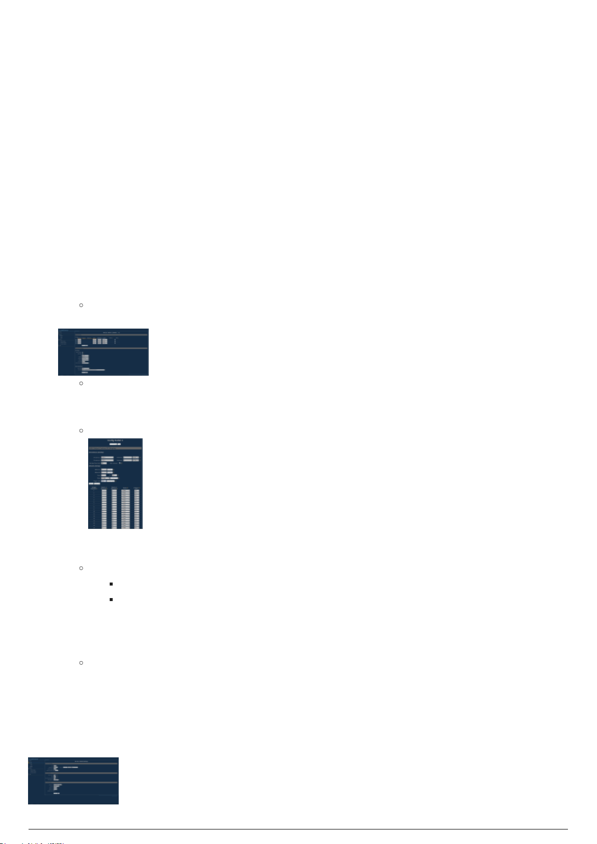
To configure a node to merge and send data via the DMX ports
To navigate to the web interface, enter the IP address of the node in your browser window.1.
Under Setup, click on the desired node you wish to configure.2.
Note: The 8 port nodes will appear as multiple 4 port nodes in the interface.
For the desired ports, choose Output as the Direction, and Custom for IP Merging.3.
Result: A blue box appears beside the number for the output after IP Merging is set to
Custom.
Click on this blue box beside the number for the output.4.
Result: The Config Outlet window for that output appears.
Set the universes you wish to merge. Source one chooses the DMX protocol, with a universe, and5.
source two chooses the RTTrPL universe.
Notes:
RTTrPL universes start from universe 0 instead of 1.
RTTrPL must be source 2.
Change the Mode to be X-Fade, set the trigger channel to be the same as your merging channel,6.
and then click Set default mode.
Click Submit Changes.7.
Result: That output will be configured as expected. If you select Show table, you should see
the channels have all changed to X-Fade, with a trigger of the specified channel.
Repeat the above for all outputs you wish to configure on the node.8.
Click Submit Changes.9.
Navigate to the Global tab under Setup. Set Enable Trigger to DMX, and the universe to whichever10.
universe your Merging Channel is patched to, with the desired DMX protocol.

To configure a node to reroute merged data to send to other DMX nodes
BlackTrax Wiki
68 of 298
5/14/2019
Note: It is recommended that the reroute is done to a universe which is different than the universes from
the console and BlackTrax. For example, if you are merging sACN universe 1, with RTTrPL universe 1, you
might re route the merged data to sACN universe 101.
To navigate to the web interface, enter the IP address of the node in your browser window.1.
Under Setup, click on the desired node you wish to configure.2.
Note: The 8 port nodes will appear as multiple 4 port nodes in the interface.
For the desired ports, choose Output as the Reroute, and Custom for IP Merging.3.
Result: A blue box appears beside the number for the output after IP Merging is set
to Custom.
Result: The port will now have an arrow leading to a box to specify the new universe to
reroute the merged data on.
Click on this blue box beside the number for the output.4.
Result: The Config Outlet window for that output appears.
Set the universes you wish to merge. Source one chooses the DMX protocol, with a universe, and5.
source two chooses the RTTrPL universe.
Notes:
RTTrPL universes start from universe 0 instead of 1.
RTTrPL must be source 2.
Change the Mode to be X-Fade, set the trigger channel to be the same as your merging channel,6.
and then click Set default mode.
Click Submit Changes.7.
Result: That output will be configured as expected. If you select Show table, you should see
the channels have all changed to X-Fade, with a trigger of the specified channel.
Repeat the above for all outputs you wish to configure on the node.8.
Click Submit Changes.9.
Navigate to the Global tab under Setup. Set Enable Trigger to DMX, and the universe to whichever10.
universe your Merging Channel is patched to, with the desired DMX protocol.

Common ArtGate Node Setup Guide
BlackTrax Wiki
69 of 298
5/14/2019
DMX nodes of the ArtGate family of models must be configured to work with your BlackTrax system.
Attention: The following guide outlines how each variable should be set for use with BlackTrax. Each
BlackTrax event is unique. There are circumstances where these settings need to be modified based on
factors such as the rig, cabling and patching.
Setup the node through a web interface, or setup the node through a BlackTrax server. Please ensure
your IP settings match that of the node(s) you wish to configure.
To configure a node
To navigate to the ArtGate model's web interface, enter the IP address of the node in your browser1.
window.
Result: The Main Settings window of the ArtGate model appears.
On the Main tab, scroll down to the Ports section.2.
For each DMX port that you want to use:3.
Set Mode/merging column to Out/ComXFade.1.
Set Pri.unv.protocol column to the desired protocol (Art-Net or sACN).2.
Set the Pri.unv.number column to the desired universe.3.
Set the Sec.unv.protocol to RTTrPL.4.
Set the Sec.unv.number to the corresponding RTTrPL universe.5.
Click Save Settings at the bottom of the page.4.
Click the Advanced tab on the main toolbar at the top of the page.5.
Result: The Advanced port settings window appears.
Notes:
Scroll down to the Advanced Port Settings section.6.
For each DMX port that you set on the Main tab:7.
Set the Trigger/XFade unv.protocol column to the desired protocol for the merge channel1.
(Art-Net or sACN).
Set the Trigger/XFade unv.number column to the universe which contains the merge2.
channel.
Set the Common Trigger/XFade control channel to the chosen DMX merge channel in the3.
above universe.
Click Save Settings at the bottom of the page.8.
RTTrPL universes start from universe 0 instead of 1.
Information updated as per ArtGate Pro firmware version 4.06.

System Procedures
BlackTrax Wiki
70 of 298
5/14/2019
Table of contents:
Licensing
Charging BTBeacons
Replacing a BTBeacon's Lithium-Ion Battery
Installing Third Party Software
Server Failover

Licensing
BlackTrax Wiki
71 of 298
5/14/2019
Licensing Overview
BlackTrax includes a licensing security system to authorize hardware devices on the BlackTrax Network.
Unrecognized devices on the BlackTrax Network are not compatible with the software. An unrecognized
device is any device on the BlackTrax Network that was not sold directly to you by CAST Software.
A BlackTrax License will authorize the use of the BlackTrax system for a restricted number of output
connections based on the type of License that was purchased. The number of output connections allowed
for each type of License varies from a minimum of 1 output connection and up to a maximum of 12
output connections, or the non-restricted Unlimited License.
The number of output connections that is authorized with the BlackTrax License is indicated in the About
BlackTrax dialog box.
Notes:
The default License Folder location is: C:\bt_run_time\license. Licenses can be downloaded from the
BlackTrax Members Only Downloader which can be found at this link.
You need to update your license if you have added new hardware devices to the network and
received an error message in BlackTrax.
You need to upgrade your license if you want to add output connections for additional unicast
outputs.
Attention: BlackTrax Licenses purchased before BlackTrax Release Version 2.2.3 will automatically
convert to the Unlimited License.

Charging BTBeacons
BlackTrax Wiki
72 of 298
5/14/2019
Charging Overview
BTBeacons are charged using the BTSmart Charger. BTBeacons can be connected to the BTSmart
Charger using the Mini USB port found on the side of the BTBeacon.
Attention:
The Mini USB port of the BTBeacon is not designed to be a peripheral device to a Class B personal
computer. As such, a user shall not connect the USB port to a Class B personal computer during
normal operation.
The sole power source of the BTBeacon is the internal 3.7V rechargeable Lithium-ion battery. The
BTBeacon does not require a connection at the Mini USB port to operate.
To charge a BTBeacon using the BTSmart Charger
Connect the BTBeacon to the charge station via the Mini USB port found on the side of the BTBeacon.
Result: The BTBeacon is charging. To determine when the BTBeacon is fully charged, see BTBeacon
status LEDs (During operation).

Replacing a BTBeacon's Lithium-Ion
BlackTrax Wiki
73 of 298
5/14/2019
Battery
BTBeacon Lithium-ion Battery Overview
After extensive use the lithium-ion battery in a BTBeacon may no longer operate and be unable to power
the BTBeacon. The lithium-ion battery’s life cycle is at its end if the lithium-ion battery will not hold a
charge and the BTBeacon will not power on. When this occurs, it is recommended that the lithium-ion
battery inside the BTBeacon be carefully replaced with a new lithium-ion battery.
Attention:
Only use lithium-ion batteries supplied by CAST. It is recommended that batteries be changed
every 6 months to ensure optimal performance.
The following are required when replacing a BTBeacon’s battery:
Replacement battery
3/8” Hex key
Adhesive tape
To replace a BTBeacon’s battery
On the BTBeacon, hold down the red Power button for 2 seconds.1.
Result: The BTBeacon will power off. No lights on the unit will be on.
Turn the BTBeacon over. Using a hex key, remove the 3/8” screws holding the case together.2.
Carefully separate the two halves of the BTBeacon case. There is a ribbon cable connecting the3.
motherboard in one half of the case, to the lithium-ion battery in the other half of the case.
Disconnect the ribbon cable from the motherboard.4.
The lithium-ion battery is attached to the case with adhesive tape. Gently remove the battery free5.
from the case.
Attention: When removing the battery, use soft tools and take care to not puncture or
damage the battery casing.
Properly dispose of the old battery.6.
Take a new battery and adhere it to the inside of the case.7.
Note: The adhesive tape must be heat resistant to function properly.
Connect the ribbon of the new battery to the motherboard.8.
Join the halves of the BTBeacon case and close the unit.9.
Fasten screws to the back of the BTBeacon case, sealing it.10.
Press the Power button down.11.
Result: The lights of the BTBeacon will flash and the unit will turn on. The BTBeacon’s
battery has successfully been replaced.
Opening the case to remove the battery

Disconnecting the ribbon cable
BlackTrax Wiki
74 of 298
5/14/2019
Adding new double sided tape, and insert new battery
Reconnecting the ribbon cable
Closing the case

Installing Third Party Software
BlackTrax Wiki
75 of 298
5/14/2019
The BTServer is a closed system. Circumventing the security measures in place on the BTSystem for any
reason, including the installation of third party software on the BTServer, is explicitly not permitted.
Circumventing the security of the BTSystem will immediately void the warranty.
This policy is in effect to protect the performance and stability of the BTSystem. Having third party
software installed might adversely affect the BTSystem.
Note: If third party software must absolutely be installed on the BTSystem, please contact CAST or your
local BTE for a possible solution. If a BTE or CAST deems the software acceptable, they may arrange to
install it for you.

Server Failover
BlackTrax Wiki
76 of 298
5/14/2019
In the event a user needs to switch from their main BT Server, to a backup BT Server, the following
procedure should be followed.
Note: Users should keep a backup of their related show files in the event they need to switch servers
during operation. Users can easily do this using BTBackup on their servers, or by manually copying the
files to a USB stick.
Only 1 instance of Motive, as well as BTEngine should be present on the network at any given time.1.
Therefore, the backup server should not have these modules open, or be disconnected from all
networks until needed.
The BlackTrax GUI, and BTWYG can be opened, with their files loaded on both servers at the
same time.
In the event of needing to switch servers, ensure the main BTServer has been disconnected from2.
it's associated networks.
On the Backup server, Launch Motive, with the correct file.3.
In the BTGUI launch BTEngine and Apply Changes.4.
From this point the show should be running as expected from the Backup Machine. Optionally, users
could have all modules and files running on the Backup Machine, with it completely disconnected from all
networks until the time of failover.

BTWYSIWYG For BlackTrax
BlackTrax Wiki
77 of 298
5/14/2019
Table of contents:
1 Preparing the BTWYG file :
1.1 Introduction :
1.2 Creating a BTWYSIWYG Project :
1.3 Saving the BTWYSIWYG Project :
1.4 Requirements for Creating the Space in BTWYSIWYG :
1.5 Defining a Common Origin in BTWYSIWYG :
1.6 Creating the Venue in BTWYSIWYG :
1.7 Creating Trackables in BTWYSIWYG :
1.8 Patching Trackables in BTWYSIWYG :
1.9 Hanging Moving Fixtures in BTWYSIWYG :
1.10 Best Practices for Moving Fixture Placement :
1.11 Patching and Assigning an ID to Fixtures in BTWYSIWYG :
1.12 Patching DMX Universes to a Console :
1.13 Patching Universes to BlackTrax :
1.14 Applying BTX information to BlackTrax from BTWYSIWYG :
2 Optional .BTX Information :
2.1 BlackTrax Zones :
3 Planning BTSensor Placement :
3.1 Introduction :
3.2 BTSensor Placement :
4 BlackTrax Visualization :
4.1 Introduction :
4.2 Using BTWYSIWYG as a Tracking Visualizer :
4.3 Using Calibration Data to Adjust Visualization in BTWYSIWYG :
4.4 Using Stick Beams for Fixtures in BTWYSIWYG :
4.5 Shaded View Camera Control :

Preparing the BTWYG file
BlackTrax Wiki
78 of 298
5/14/2019
Table of contents:
Introduction
Creating a BTWYSIWYG Project
Saving the BTWYSIWYG Project
Requirements for Creating the Space in BTWYSIWYG
Defining a Common Origin in BTWYSIWYG
Creating the Venue in BTWYSIWYG
Creating Trackables in BTWYSIWYG
Patching Trackables in BTWYSIWYG
Hanging Moving Fixtures in BTWYSIWYG
Best Practices for Moving Fixture Placement
Patching and Assigning an ID to Fixtures in BTWYSIWYG
Patching DMX Universes to a Console
Patching Universes to BlackTrax
Applying BTX information to BlackTrax from BTWYSIWYG

BTWYG Introduction
BlackTrax Wiki
79 of 298
5/14/2019
BTWYSIWYG is an award-winning program that offers lighting designers a customized 3D CAD, reporting
and pre-visualization application which is included in the BlackTrax software suite. Using BTWYSIWYG will
let you create a virtual representation of the Space.
BTWYSIWYG exports this information as a .btx file, which is then used by BlackTrax as a blueprint for
tracking in the Space. If you are tracking with moving fixtures, fixture position and patching must also be
included in the .btx file.
When connected to BlackTrax, BTWYSIWYG can act as a visualizer for what is happening in the Space.
Trackable and fixture movement can be fully simulated, using information from BlackTrax or other data
sources.
The following section on BTWYSIWYG covers only the features directly related to BlackTrax. For an indepth understanding of BTWYSIWYG and its full capabilities, please refer to the current WYSIWYG
Reference Guide.
Tip: A registered BlackTrax Expert can be consulted to assist with any portion of a BlackTrax project,
including transferring information from BTWYSIWYG to BlackTrax.

Creating a BTWYSIWYG Project
BlackTrax Wiki
80 of 298
5/14/2019
Creating a BTWYSIWYG Project from BlackTrax
When a new BlackTrax project is launched from the Portfolio Manager for the first time, a new
BTWYSIWYG project associated with the launched BlackTrax project is automatically created and opens
by default.
When a new BTWYSIWYG project is created from BlackTrax, all necessary settings and configurations are
automatically applied to that new BTWYSIWYG project. These template projects simplify the setup
process for BTWYSIWYG on new installations.
Creating and launching the new BTWYSIWYG project from the BlackTrax Portfolio Manager will
automatically start BTWYSIWYG in a state that is ready for BlackTrax use.
In the Editing section of the System Configuration widget in BlackTrax, you can set the BTWYSIWYG file
to automatically open after the associated BlackTrax file launches from the Portfolio Manager.
See Editing section for more details.
Notes:
We recommend creating and launching the new BTWYSIWYG project from the BlackTrax Portfolio
Manager which is more convenient than having to manually create the new project and settings in
BTWYSIWYG.
The BTWYSIWYG file associated with a BlackTrax project can also be launched via the BTWYG
option under the Modules menu.
Creating a New BTWYSIWYG Project
in BTWYSIWYG
The New command creates a new show document and will be saved as a ".wyg" file.
To create a new BTWYSIWYG project
In BTWYSIWYG, on the Welcome Screen, click File to choose New.1.
Result: The BTWYSIWYG opens a new show file in CAD.
BTWYG Welcome Screen

Saving the BTWYSIWYG Project
BlackTrax Wiki
81 of 298
5/14/2019
Once you have all the information on the Space that was created in BTWYSIWYG, the information must
be saved as a BTWYSIWYG project file (.wyg). Save will save the open BTWYSIWYG project to the same
file name and location under which it was previously saved. If you are saving the project for the first
time, this command will perform Save As..., which will save the current project with a new file name
and/or a new destination.
To save the BTWYSIWYG project using Save
In BTWYSIWYG, from the File menu, choose Save.1.
Result: The Save as window appears.
In the window, navigate to where you want to save the project file.2.
In the File name field type in the name of the project.3.
Click Save.4.
To save the BTWYSIWYG project using Save As...
In BTWYSIWYG, from the File menu, choose Save As.1.
Result: The Save as window appears.
In the window, navigate to where you want to save the project file.2.
In the File name field type in the name of the project.3.
Click Save.4.

Requirements for Creating the Space in
BlackTrax Wiki
82 of 298
5/14/2019
BTWYSIWYG
To use BlackTrax you are required to create a virtual representation of the Space in BTWYSIWYG. This
virtual Space will possess vital information that BlackTrax requires as follows: what the dimensions and
tracking area of the Space are, what objects or people you want BlackTrax to follow (Trackables), and
information on devices in use (e.g., fixtures). This section will guide you on creating the Space in
BTWYSIWYG and aspects that must be included.
To create the BTWYSIWYG file for tracking with moving fixtures in BlackTrax, follow these
mandatory steps
Define a common origin position in the Space. (Default set in template file.)1.
Create and patch Trackables to a motion universe and assign avatars. (Default set in2.
template file.)
Hang moving fixtures approximately where they will be in the venue with the correct orientation.3.
Patch fixtures to DMX universe and assign Spot IDs.4.
Patch DMX universes to console. (Default set in template file.)5.
Patch all created universes to BlackTrax. (Default set in template file.)6.
Save the BTWYSIWYG project. 7.
Export the BTWYSIWYG project for use with BlackTrax. (Default set in template file.)8.
Tip: Some of the required steps are set by default when the BlackTrax Template file is used in
creating a BlackTrax Portfolio, or from the Templates section in BTWYSIWYG.
To create the BTWYSIWYG file NOT for tracking with moving fixtures, follow these mandatory
steps
Define a common origin position in the Space. (Default set in template file.)1.
Create and patch Trackables to a motion universe and assign avatars. (Default set in2.
template file.)
Patch all created universes to BlackTrax. (Default set in template file.)3.
Save the BTWYSIWYG project.4.
Export the BTWYSIWYG project for use with BlackTrax. (Default set in template file.)5.
Tip: Some of the required steps are set by default when the BlackTrax Template file is used in
creating a BlackTrax Portfolio, or from the Templates section in BTWYSIWYG.
BTWYG file with patched fixtures and a trackable

Defining a Common Origin in
BlackTrax Wiki
83 of 298
5/14/2019
BTWYSIWYG
Origin Introduction
Most objects in BTWYSIWYG are drawn as 3D objects, with width, depth, and height values using the
Cartesian coordinate system of 3 working axes, X, Y, and Z. The point where the 3 axes meet is called
the origin and the value of X, Y, and Z is 0 respectively (0,0,0).
By default, the origin will be in the center of the WYSIWYG project. This default origin is called the
Document Origin. It is possible to move the origin from its default location to a new position. This origin is
called the User Origin.
CAD mode with a frame representing the default origin
Origin Requirements
The location of the origin is recommended to be inside the Space.
The origin should be easy to see and determine in the Physical Space.
The origin in the Physical Space needs to be visible to at least 2 BTSensors for BTSensor calibration
to function.
The location of the origin needs to be consistent. The origin needs to be the same in the
BTWYSIWYG virtual Space, in Motive, in the Physical Space and any Third Party Programs
connected to BlackTrax. Inconsistencies will cause errors in the BTSystem and any connected
downstream technologies.
The alignment of the ground plane in relation to the axes needs to be the same in the BTWYSIWYG
virtual Space, in Motive, and in the Physical Space. It is recommended that the following
conventions are followed when aligning the origin:
The +Y axis directed Upstage.
The +X axis is directed Stage Left.
The +Z axis is directed vertically towards the ceiling.
Ruler Tool
The Ruler Tool helps you design your show file in the Wireframe views of the CAD mode, providing a
visual aid for coordinate reference and measurement. By default, the ruler is aligned with the document
origin and displays coordinate information along the top and left side of the view. Its scale matches the
default grid scale. The ruler has different colors to represent different axes (X=Red, Y=Green, Z=Blue).
X Axis Ruler

Y Axis Ruler
BlackTrax Wiki
84 of 298
5/14/2019
Z Axis Ruler
Ruler Icons
Document Origin: The document origin icon appears when the Ruler’s zero position (origin) is aligned
with the Document Origin, which is set by default to be the center point of the BTWYSIWYG venue
defined for the event.
Document Origin Icon
User Origin: The user origin icon appears when you have set a new User Origin for the file.
User Origin Icon

Creating the Venue in BTWYSIWYG
BlackTrax Wiki
85 of 298
5/14/2019
Using the tools in BTWYSIWYG’s CAD mode, create an accurate scale representation the venue Space is
in. The suggested minimum level of detail is that it contains the floor, the walls and any pipes, trusses or
structural frames in which BTSensors or moving fixtures will be attached. The more detailed the venue,
the better looking and accurate the visualization will be.
Attention: Fixtures need to be attached to pipe or truss to be inserted. You may also insert fixtures on
the floor, but you won't be able to spin them using Fixture Properties.
Note: Due to the complexity of recreating an accurate representation of a venue, refer to the WYSIWYG
Reference Guide’s chapter on The CAD environment for a thorough understanding.
Creating Trackables in BTWYSIWYG
BlackTrax Wiki
86 of 298
5/14/2019
Trackables are objects or people that are to be tracked. A Trackable can be represented by a library
object from the Library Browser, or on a drawn object like a sphere or riser. Trackables are created on
the Trackables/Motion layer by default.
Important Notes:
Trackables are automatically named and patched when created.
By default, when a New Portfolio is launched from BlackTrax, BTWYSIWYG opens with 12
Trackables.
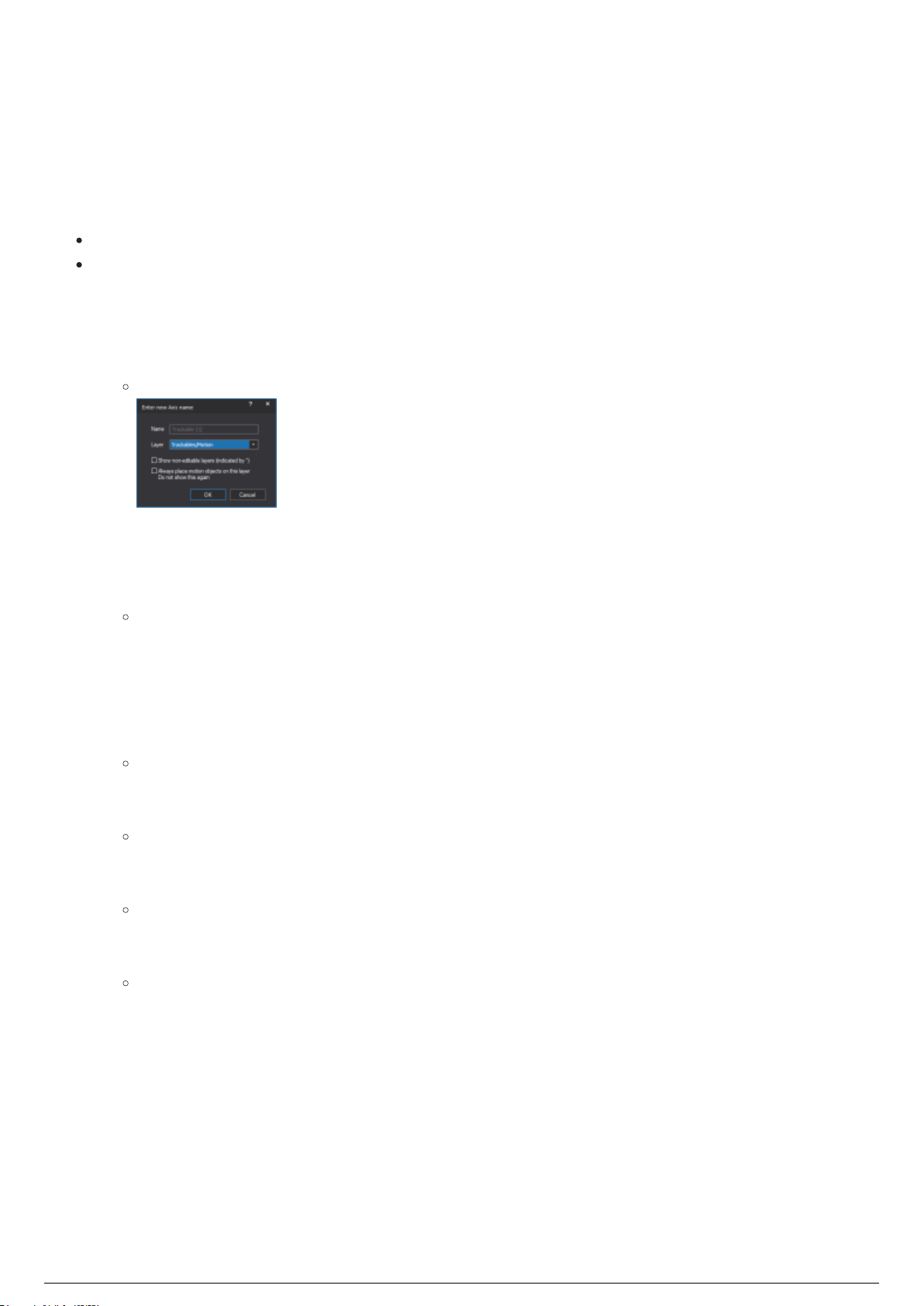
To create a trackable in BTWYSIWYG
In BTWYSIWYG CAD mode, from the BlackTrax menu, choose BT Trackable.1.
Result: The Enter new Axis name window appears.
In the Enter new Axis name window, click the layer for the Trackable from the Layer drop-down list.2.
You can also select the checkboxes to enable the other options for the layer display.3.
Click OK.4.
On your drawing, click where you wish to place your Trackable.5.
Result: A Trackable object appears where the mouse was clicked. The Trackable object is
represented as a Cartesian axis.
To add a library object to your trackable
In BTWYSIWYG CAD mode, at the bottom of the screen, click the Wireframe view tab.1.
From the LIBRARY menu, choose Browse Library.2.
Result: The Library Browser window appears.
At the bottom of the Library Browser window, click the Library items tab to display the contents.3.
Navigate to the desired object you wish to represent a Trackable.4.
Note: The actual look of the Trackable is purely cosmetic and will only represent the
Trackable's position in the visualization.
At the top of the Library Browser, click the Insert tool.5.
Tip: You can also double-click the object name.
To insert the object, click on your drawing to place the object where you want in relation to the6.
Trackable.
Tip: You should place the object relative to the drawn Trackable where the stringers will be
on your physical tracked object. The object will then move and rotate around the centroid of
the Trackable.
To stop inserting the object, right-click on the drawing and select Finish Library Item from the7.
menu that appears.
Right-click on the Trackable object you inserted on the drawing.8.
From the menu that appears, select Properties.9.
On the General tab, from the Attach to Axis drop-down list, select the Trackable object you wish to10.
assign the Library object to.
Click OK.11.
Result: The Trackable is represented as the inserted object and its motion is associated with the

BTTrackable.
BlackTrax Wiki
87 of 298
5/14/2019
Trackable object with a person attached
Note: The BlackTrax Template file has one Trackable and avatar created and patched by default. It is
possible to create multiple Trackables at once using the array tool in BTWYSIWYG, and this created
Trackable. See the Array section in the WYSIWYG Reference Guide for more information.

Patching Trackables in BTWYSIWYG
BlackTrax Wiki
88 of 298
5/14/2019
Patching Trackables Introduction
Important Note: As of BlackTrax v2.2, the Quick Motion Patch Tool is no longer required to patch
Trackables because Trackables are automatically named and patched when inserted.
Trackables that are created need to be patched to a Motion Universe. The patch allows the visualization
of Trackable movement in BlackTrax. This section shows how to easily patch Trackables using the Quick
Motion Patch Tool, as well as the manual way to patch each Trackable.
Note: Read the WYSIWYG Reference Guide’s chapter on Data mode for a complete understanding of
patching manually assigned Trackables.
Quick Motion Patch Tool
Patching Trackables Using Quick Motion Patch Tool
To patch all trackables using the quick motion patch tool
From the Tools menu, choose Quick Tools and then choose Quick Motion Patch Tool.1.
Under the Auto-Patch Motion section, ensure that All Trackable/Axes is selected.2.
Click Patch.3.
Note: If the motion universe BT-Trackables does not yet exist in the file, BTWYSIWYG will
ask in a dialog box if you wish to create it. In the dialog box, click Yes to create the motion
universe.
Result: The Trackables are patched to the motion universe. The total number of Trackables
patched will be reported at the bottom of the window.
Click Close.4.
To patch only selected trackables using the quick motion patch tool
Select all Trackables you wish to patch in one of the wireframe views.1.
Tip: Remember that the Trackable is the Cartesian axis associated with the Trackable, not
the Trackable object itself.
From the Tools menu, choose Quick Tools and then choose Quick Motion Patch Tool.2.
Under the Auto-Patch Motion section, ensure that Only Selected Trackable/Axes is selected.3.
Click Patch.4.
Note: If the motion universe BT-Trackables does not yet exist in the file, BTWYSIWYG will
ask in a dialog box if you wish to create it. In the dialog box, click Yes to create the motion
universe.
Result: The Trackables are patched to the motion universe. The total number of Trackables
patched will be reported at the bottom of the window.
Click Close.5.
To clear all trackables' patch using the quick motion patch tool

From the Tools menu, choose Quick Tools and then choose Quick Motion Patch Tool.1.
BlackTrax Wiki
89 of 298
5/14/2019
Under the Clear Motion Patch section, ensure that All Trackable/Axes is selected.2.
Click Clear.3.
Result: All Trackables are unpatched from the motion universe. The total number of patched
Trackables removed will be reported at the bottom of the window.
Click Close.4.
To clear only selected trackables' patch using the quick motion patch tool
Select all trackables you wish to clear patch info for in one of the Wireframe views.1.
Tip: Remember that the Trackable is the Cartesian axis associated with the Trackable, not
the Trackable object itself.
From the Tools menu, choose Quick Tools and then choose Quick Motion Patch Tool.2.
Under the Clear Motion Patch section, ensure that Only Selected Trackable/Axes is selected.3.
Click Clear.4.
Result: All selected Trackables are unpatched from the motion universe. The total number of
patched Trackables cleared will be reported at the bottom of the window.
Click Close.5.

Hanging Moving Fixtures in BTWYSIWYG
BlackTrax Wiki
90 of 298
5/14/2019
If you want moving fixtures to follow a Trackable, you must place and hang the moving fixtures in
BTWYSIWYG. When a moving fixture is placed in BTWYSIWYG, BlackTrax collects valuable fixture
information such as the properties, range of capabilities, orientation and position in the venue.
Moving fixtures must be placed on the floor or hung onto pipes or trusses. The position and orientation of
the fixtures in BTWYSIWYG must be close to their location in the actual Space for tracking to work
correctly.
Attention:
Calibration can resolve the fixtures' incorrect locations or backward orientation, but the calibration
process is tedious. The fixtures in the actual Space should match their virtual fixture orientation
and location to make calibration easier.
Library objects that are classified as moving lights are capable of following Trackables.
Tip: To keep fixture orientation consistent, make a note on the orientation of the fixture’s tail. This
provides an accurate indication of the fixture's orientation.
Note: Read the WYSIWYG Reference Guide’s chapter on Hanging and focusing fixtures for a complete
understanding on how to hang fixtures.
To insert fixtures in BTWYSIWYG
In BTWYSIWYG CAD mode, at the bottom of the screen, click the Wireframe view tab.1.
From the Library menu, choose Browse Library.2.
Result: The Library Browser window appears.
At the bottom of the Library Browser click Fixture Tool.3.
On the menu that is now visible, double-click Manufacturer to select fixtures by manufacturer4.
name, Type to select by fixture type, or All to see all the fixtures in alphabetical order.
Note: Alternately, you can use the Library Browser's search function to locate the fixture that
you want to insert. Simply type the name of the fixture (or a partial name) in the search box
at the top of the Library Browser, and then click the Search icon.
Double-click the fixture name.5.
Result: A fixture with default settings for this type attaches to the cursor.
To change the properties of the fixture before inserting, in the Library Browser right-click on the6.
fixture name. On the menu that appears, click Properties.
Result: A dialog box opens with a shaded view of the fixture on the left and an image of its
symbol on the right. Change the properties as needed.
To place the fixture, click over a hang structure.7.
Result: Copies of the fixture attaches to hang structures when clicked. Continue placing this
type of fixture by clicking on the other hang structures as desired.
Right-click to finish placing this fixture type. On the menu that appears select Finish placing8.
fixtures.
Note: Alternately, clicking ESC will finish placing fixtures.
To place other fixture types, repeat the above steps for each type.9.
Attention: Fixtures intended for tracking must not hang directly over the Space.
When placing moving fixtures that are to follow Trackables, it is recommended that fixtures
are not hung directly above the Space. Fixtures hung above the Space may run into pan and
tilt range limitations when attempting to follow a Trackable.
Fixtures placed on a pipe

Best Practices for Moving Fixture
BlackTrax Wiki
91 of 298
5/14/2019
Placement
To obtain precise tracking in BlackTrax, the limitations of moving fixtures must be taken into account.
The following section will guide you through known limitations of moving fixtures in BlackTrax and
provide smart practices used to overcome these limits.
Attention: Do not place fixtures that will track directly above the Space.
A number of issues can occur if fixtures are directly above the Space. If fixtures are placed above the
Space and are following a Trackable which moves in a circular path underneath, this can cause fixtures
to spiral and reach a pan stop.
Note: BlackTrax has a feature where if a fixture pan-flips, the fixture will dim while performing the flip.
This is in place to reduce the disruption caused by the pan-flip during operation.
Tips:
Prediction algorithms can be selected when tracking to try and achieve specific tracking needs. See
Fixture Sensitivity for more information.
To avoid these problems, it is recommended that moving fixtures are instead placed in front,
behind, or on the sides of the Space. This will limit the range of both pan and tilt movement needed
by fixtures to follow a Trackable and avoid these potential problems.
If tracking must occur below a fixture, a possible solution is to hang the fixture sideways.
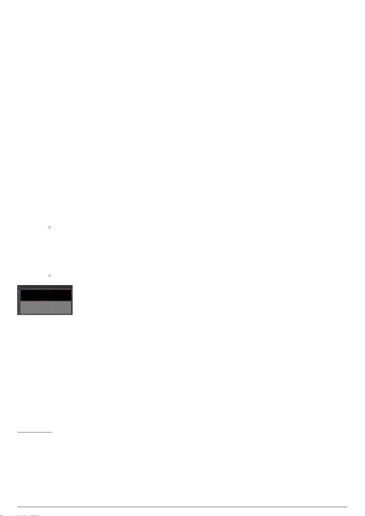
Patching and Assigning an ID to Fixtures
BlackTrax Wiki
92 of 298
5/14/2019
in BTWYSIWYG
Patching Fixtures to BTWYSIWYG Introduction
When a new BTWYSIWYG project is created from BlackTrax, DMX universes are automatically created
and patched 1:1 by default.
When tracking occurs, BlackTrax uses the DMX values generated by the console, but overrides the pan
and tilt channels with new values. These new values direct the fixture to aim and follow a Trackable. If a
fixture was edited to have a constant beam size, the zoom and iris values will also change. The patching
must be the same so that BlackTrax can override the correct DMX universe and channels.
In BTWYSIWYG, you can create and patch a DMX universe using the spreadsheet in DATA mode or Quick
Tools.
To create a DMX universe
In BTWYSIWYG DATA mode, click the Patch layout tab at the bottom of the screen.1.
Right-click on the patch shortcut area on the right of the screen.2.
On the menu that appears click New Patch.3.
Result: The Enter new Patch Universe name dialog box appears, prompting for the type of
universe that you want to create and the name of the new universe.
Type the name of the patch universe.4.
Under Patch Universe Type, select DMX.5.
Click OK.6.
Result: The patch shortcut appears in the Patch tab.
DATA Mode with one DMX universe created
Assigning Spot ID Numbers to Fixtures
An individual Spot ID number must be assigned to every single fixture in the project in BTWYSIWYG. This
Spot ID number will map to a fixture ID on a connected lighting console. The Spot ID is used by the
BTSystem to differentiate between fixtures in the project.
Fixture Patching Methods
There are multiple ways to patch fixtures in BTWYSIWYG. The following section will guide you through
some of the simplest methods. For more information see the WYSIWYG Reference Guide’s chapter on
Data mode.
To patch fixtures and assign spot IDs using quick tools
Use Quick Tools and click on the fixtures in Wireframe view to patch and assign spot IDs. The first fixture
clicked will be assigned the patch and ID as configured in Quick Tools. The next fixture clicked will be
assigned the next available channel in the patch and the next fixture ID in the sequence until you are
finished using Quick Tools.

In BTWYSIWYG CAD mode Wireframe view, from the Tools menu, choose Quick Tools and then1.
BlackTrax Wiki
93 of 298
5/14/2019
choose Quick Tools. Alternately click the Quick Tools icon in the Tools toolbar.
Result: The Quick Fixture Tool window appears.
In the Quick Fixture Tool window, in the Fixture Attributes section, select the Spot checkbox.2.
In the Spot field, enter a number which will be the first fixture ID used in the sequence.3.
In the Fixture Data section, select the Patch checkbox.4.
In the Patch field, enter the universe and channel the first fixture will patch to, separated by a5.
period.
Example: “A.1” would patch to universe A, address 1.
Click Ok.6.
Result: When a fixture is selected, it will be assigned a Universe and channel to operate on.
The first fixture selected will be assigned the to the channel number entered in Quick Tools.
Subsequent fixtures selected will be assigned the next sequential channel and Spot ID
number.
Click on a fixture to patch it to a universe and channel. Click on each fixture that you want to be7.
patched and assigned a spot ID.
To stop patching fixtures, right-click.8.
On the menu that appears, click Finish Quick Tools.9.
Quick Tools
To patch fixtures and assign spot IDs using the data spreadsheet
The Spreadsheet view In DATA mode displays information on all fixtures created in the BTWYSIWYG
project. You can edit the patch information and Spot ID directly in the spreadsheet table.
In BTWYSIWYG DATA mode, click on the Spreadsheet tab.1.
In the Columns section on the left side of the window, click All Data (Sortable).2.
Result: All fixture data are displayed in the spreadsheet.
In the Patch column, enter the appropriate patch information for each fixture.3.
In the Spot column, enter a unique Spot ID for each fixture.4.
Tip: It is possible to assign sequential values to fixtures quickly by selected all fields for the
fixtures you wish to edit (for example all spot ID fields for all fixtures) and type the spot ID of
the starting fixture and a '+' and hitting enter. For example, 101+ will set the first fixture to
spot 101, and every fixture after that will increase by 1. If this method is used to assign
values, it is recommended that fixtures are first sorted so fixtures are organized. Fixtures can
be sorted in order of position, or Unit # along a pipe/truss. This can also be used for patching
fixtures as well.
DATA>Spreadsheet with fixtures patched for BlackTrax

Patching DMX Universes to a Console
BlackTrax Wiki
94 of 298
5/14/2019
BlackTrax requires that the patching information of the connected console be recorded in BTWYSIWYG.
This will inform BlackTrax which console is in use and which ports will transmit information.
When a new BTWYSIWYG project is created from BlackTrax, DMX universes are automatically created
and patched 1:1 by default.
You can also patch the DMX universes to a DMX console in the Device Manager window in BTWYSIWYG.
Note: The DMX console used in BlackTrax and displayed in the Device Manager window in BTWYSIWYG is
an sACN device. This device will also work with Art-Net without any changes.
To patch the DMX universe to a console
In BTWYSIWYG LIVE mode, from the Managers menu, choose Device Manager.1.
Result: The Device Manager window appears.
In the Device Manager window, click New.2.
Result: The Library Selection window appears.
Navigate through the console library until you find the console or device that you are connecting3.
to. Click the console name to highlight it.
Click Insert.4.
Result: The console appears in the Device Manager window.
With the console name still selected, click Properties.5.
Result: The Properties window appears.
From the Protocol drop-down list, select the protocol used by the console.6.
Result: The console model is displayed in the Model field. The name of the console is
displayed in the Name field.
In the Address field, type the designated address of the console, if applicable.7.
You must bind output ports from the console to BTWYSIWYG patch universes. Bind a Port output to8.
the appropriate universe by clicking the Universe field next to the output.
Result: A drop-down list of available Universes is displayed.
Select the appropriate Universe from the list.9.
Repeat the above steps to bind all ports to their appropriate patch universes.10.
Click Close to close the Properties window.11.
Click Close to exit the Device Manager window.12.
Result: BlackTrax will know which console will be connected and which ports will transmit
information
Device Manager with an Art-Net device and a BlackTrax console
Art-Net Device Properties with patched universes

Patching Universes to BlackTrax
BlackTrax Wiki
95 of 298
5/14/2019
When a new BTWYSIWYG project is created from BlackTrax, DMX universes are automatically created
and patched to BlackTrax 1:1 by default.
You can also patch the DMX universes to the BlackTrax Network in the Device Manager window in
BTWYSIWYG.
After universes are created, be it motion or DMX, this information will need to be patched to BlackTrax.
This will inform BlackTrax which of its ports are in use and which ports will transmit information.
To patch universes to BlackTrax
In BTWYSIWYG LIVE mode, from the Managers menu, choose Device Manager.1.
Result: The Device Manager window appears.
In the Device Manager window, click New.2.
Result: The Library Selection window appears.
In the Library Selection window, in the Search field, type BlackTrax Network and then click the3.
Search icon.
Result: The device BlackTrax Network will be displayed in the search results.
Click on BlackTrax Network from the list to highlight it, then click Insert.4.
Result: The BlackTrax Network appears in the Device Manager.
With the BlackTrax Network name still selected, click Properties.5.
Result: The Properties window appears.
You must bind output ports from the BlackTrax Network to BTWYSIWYG patch universes. Bind a6.
Port output to the appropriate universe by clicking the Universe field next to the output.
Result: A drop-down list of available Universes is displayed.
Select the appropriate Universe from the list.7.
Repeat the above steps to bind all ports to their appropriate patch universes.8.
Click Close to close the Properties window.9.
Click Close to exit the Device Manager.10.
Result: BlackTrax will know what ports are in use.
Device Manager with an Art-Net device and a BlackTrax console
The BlackTrax Console with Motion and DMX universes patches
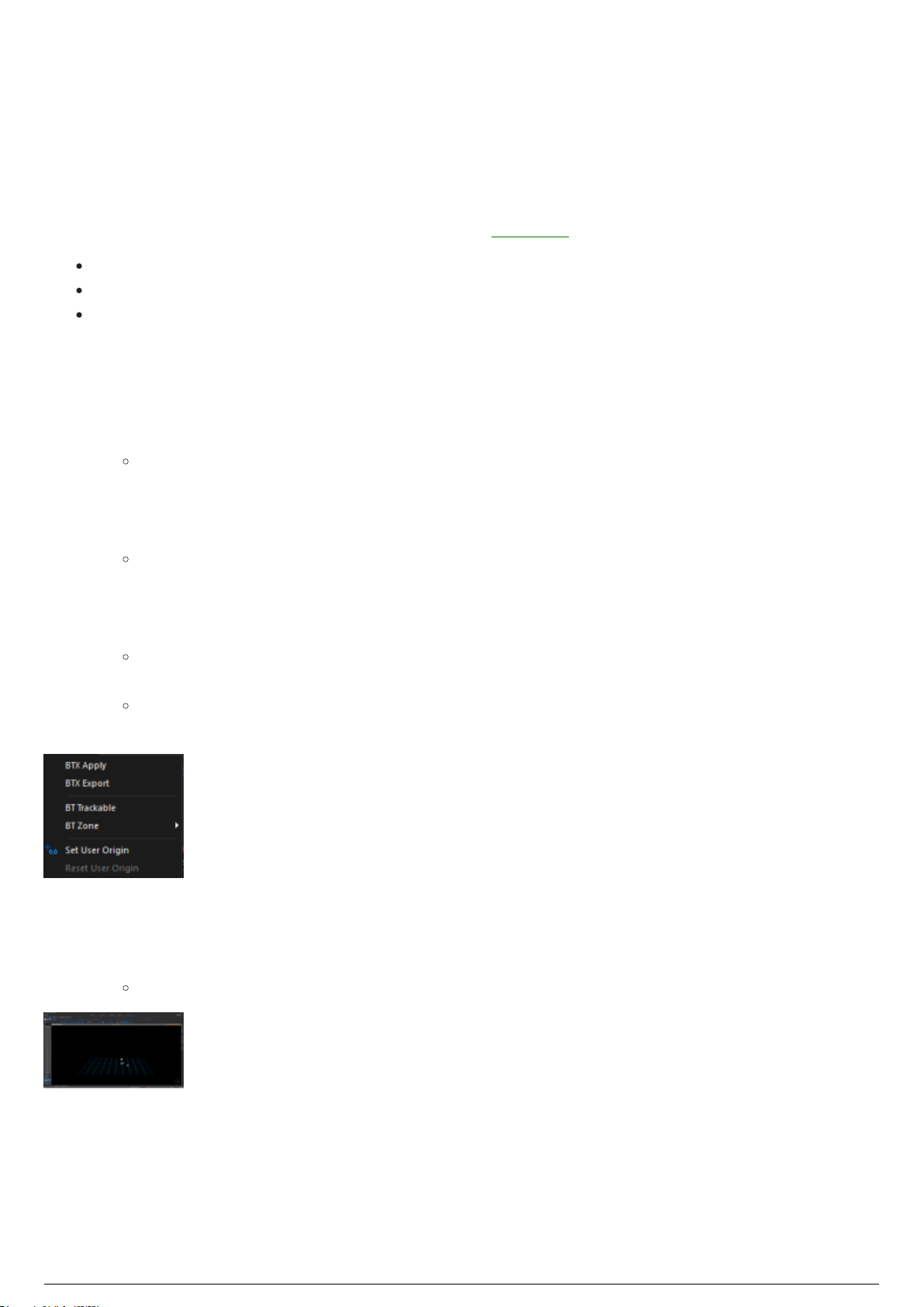
Applying BTX information to BlackTrax
BlackTrax Wiki
96 of 298
5/14/2019
from BTWYSIWYG
After a project is created, modified and saved in BTWYSIWYG, the new information must be sent and
applied to the BlackTrax Project.
There are three methods for sending BTX information to BlackTrax from BTWYSIWYG:
BTX Apply in LIVE mode
BTX Export in CAD mode
BTX Apply in CAD mode
To send BTX information with BTX Apply in BTWYSIWYG LIVE mode
In BTWYSIWYG LIVE mode, open the BlackTrax window.1.
Ensure that the BlackTrax Portfolio is open, and BTWYSIWYG is connected to it.2.
In the BlackTrax window of BTWYSIWYG , click BTX Apply.3.
Result: BTWYSIWYG sends the BTX information to the BlackTrax Project.
To send BTX information with BTX Export in BTWYSIWYG CAD mode
In BTWYSIWYG CAD mode, from the BlackTrax menu, choose BTX Export.1.
Result: A Save as window appears.
In the window, navigate to where you want to save the project file.2.
In the File name field type in the name of the project.3.
Click Save.4.
Result: The BTX information from BTWYSIWYG is exported and saved as a separate file
which can be used to manually update your BlackTrax Project.
Note: If there are errors in the export, BTWYSIWYG will display the errors after the export is
completed.
BlackTrax Menu found in CAD mode
To send BTX information with BTX Apply in BTWYSIWYG CAD mode
Ensure that the BlackTrax Portfolio is open, and BTWYSIWYG is connected to it.1.
In BTWYSIWYG CAD mode, from the BlackTrax menu, choose BTX Apply. 2.
Result: BTWYSIWYG sends the BTX information to the BlackTrax Project.
LIVE mode showing the BlackTrax panel with BTX Apply

Optional .BTX Information
BlackTrax Wiki
97 of 298
5/14/2019
Table of contents:
BlackTrax Zones

BlackTrax Zones
BlackTrax Wiki
98 of 298
5/14/2019
Three-dimensional areas called Zones, can be drawn inside the virtual representation of the Space
in BTWYSIWYG. Zones are an incorporeal volume and can only be viewed in BTWYSIWYG, but if created,
exists simultaneously in the virtual and physical Space. Zones are available in rectangular, cylindrical
and spherical shapes of any size.
BlackTrax has a number of preset interaction between Zones and fixtures, which can be accessed in the
Chapter section in BlackTrax. For more information see To enable a Zone for a Fixture.
To draw a rectangular zone
In BTWYSIWYG CAD mode, click the Wireframe view tab.1.
From the BlackTrax menu, choose BT Zone and then choose Rectangular Zone.2.
Result: The New Rectangular Zone window appears.
In the New Rectangular Zone window, in the Width field, enter in the width of the Zone.3.
In the Depth field, enter in the depth of the Zone.4.
In the Height field, enter in the depth of the Zone.5.
Note: Alternately, Zone dimensions can be created by selecting Interactive. The Zone is then
drawn in Wireframe view, and dimensions are automatically recorded.
In the Zone Name field, enter a unique name for the Zone.6.
Click OK.7.
Result: The Zone will be inserted into the Space. It can be repositioned by dragging and
dropping where needed. The dimensions of the Zone can be altered by manipulating the
Zone directly, or by right-clicking the Zone and selecting Properties.
BTWYG drawing with a Rectangular Zone selected
To draw a cylindrical zone
In BTWYSIWYG CAD mode, click the Wireframe view tab.1.
From the BlackTrax menu, choose BT Zone and then choose Cylindrical Zone.2.
Result: The New Cylindrical Zone window appears.
In the New Cylindrical Zone window, in the Height field, enter the height of the Zone.3.
In the Horizontal Radius field, enter in the horizontal radius of the Zone.4.
In the Vertical Radius field, enter in the vertical radius of the Zone.5.
Note: Alternately, Zone dimensions can be created by selecting Interactive. The Zone is then
drawn in Wireframe view, and dimensions are automatically recorded.
Lock Ratio controls the aspect ratio of the radius. This feature is enabled by default. To disable,6.
clear the Lock Ratio checkbox.
Number of Segments controls how many segments make up the radius of the cylindrical Zone. The7.
default is set to 16. To change the number of segments, clear the Use Document Defaults
checkbox. Enter the new segment number in the field.
Note: The maximum number of segments allowed is 40.
In the Zone Name field, enter a unique name for the Zone.8.
Click OK.9.
Result: The Zone will be inserted into the Space. It can be repositioned by dragging and

dropping where needed. The dimensions of the Zone can be altered by manipulating the
BlackTrax Wiki
99 of 298
5/14/2019
Zone directly, or by right-clicking the Zone and selecting Properties.
BTWYG drawing with a Cylindrical Zone selected
To draw a spherical zone
In BTWYSIWYG CAD mode, click the Wireframe view tab.1.
From the BlackTrax menu, choose BT Zone and then choose Spherical Zone.2.
Result: The New Spherical Zone window appears.
In the New Spherical Zone window, in the Horizontal Radius field, enter in the horizontal radius of3.
the Zone.
In the Vertical Radius field, enter in the vertical radius of the Zone.4.
Note: Alternately, Zone dimensions can be created by selecting Interactive. The Zone is then
drawn in Wireframe view, and dimensions are automatically recorded.
Lock Ratio controls the aspect ratio of the radius. This feature is enabled by default. To disable,5.
clear the Lock Ratio checkbox.
Number of Segments controls how many segments make up the radius of the spherical Zone. The6.
default is set to 12. To change the number of segments, clear the Use Document Defaults
checkbox. Enter the new segment number in the field.
Note: The maximum number of segments allowed is 40.
In the Zone Name field, enter a unique name for the Zone.7.
Click OK.8.
Result: The Zone will be inserted into the Space. It can be repositioned by dragging and
dropping where needed. The dimensions of the Zone can be altered by manipulating the
Zone directly, or by right-clicking the Zone and selecting Properties.
BTWYG drawing with a Spherical Zone selected

Planning BTSensor Placement
BlackTrax Wiki
100 of 298
5/14/2019
Table of contents:
Introduction
BTSensor Placement
 Loading...