

ULTIMATE SMART CAR DVR
BLACKSYS CL-100B
USER MANUAL
2CH Full HD Car DVR with brilliant image
Simultaneous recording of front view with Full HD resolution
(1920x1080, 25fps) and rear view with HD resolution (1280x720,
25fps) provides super high quality videos.
www.blacksys.co.kr/en

Notice
This product helps you to use the recorded video as a reference in case of car accident. The recorded video by this product carries no legal binding force.
CammSys will not be responsible for any legal conict and damage caused by recorded or non-recorded video.
• For safety, do not operate this product while driving such action may result in injury or accident.
• An accident at very low speed or impact may not trigger emergency recording and could be recorded as a normal file.
• Recording may not be executed in case the product is defect caused by car accident or other reason.
• Recording can be distorted under the condition where brightness suddenly changes like passing through a tunnel,
direct sunlight reflection during the day time or where light is not available at night time.
• All right to hardware, software and relevant data are reserved by CammSys Corp. and protected under copyright law.
In case of illegal copy and process, not only civil compensation but also criminal punishment based on protection of intellectual property
rights can be engaged.
• Do not use the product for other purpose rather than Car DVR.
• In case of recording other’s voice without permission, you will be liable for legal responsibility.
(In case that you save other person’s voice without any permission, be cautious that you may have legal liability)
• CammSys will not be held responsible for any damage caused by negligence, careless and improper management of user.
• Cammsys do not ensure that record all the accidents in case of not operating 3D G-Sensor with subtle impact.
• Cammsys will not be held responsible for any loss caused by malfunctions or loss of recorded image from external influences or accidents.
Notice
02

Table of contents
Notice
02
04 Caution
04 … Installation and Maintenance
06 … SD Card Use
06 … Use of Power
07 … OBD Management
08 Main features
13 Components
13 … Standard Components
14 … Front
14 … Rear
15 … Upper Side
15 … Right Side
16 … Components of OBD Device
17 … OBD product specification
18 Installation Method
18 … Front Camera Installation
19 … Rear Camera Installation
21 … OBD Terminal Installation
24 Operating device & instructions
24 … Details on Video Record
25 … LED indicator and Voice guide
27 LCD GUI
27… LCD preview screen instruction
28… LCD main menu
30… Video recording
31… Video Playing
33… Firmware Update
34… OBD main
35… Setup and engine oil information screen
36… Screen for Malfunction Diagnosis & Trip Report
37… OBD Information
38… Configuration main menu
39… Time & System Setup
40… Display
41… Sound
42… Screen saver
43… Initialization
44… SD card format
45 PC Viewer instructions
45 … Software installation & uninstallation
46 … PC Viewer Layout
47 … Basic use
48 … Configuration
50 Firmware Update
51 How to format SD card
52 Technical Specification
53 Customer Service
54 Warranty
55 Product Warranty
Table of contents
03

Caution
Before use the product, check if operation and video recording goes well.
Installation and Product Management
• Keep the camera lens clean by preventing dust or foreign substance from coming into contact with the lens. Otherwise, this may result in video
distortion. So keep the area clear around the installed camera. If another object is placed around, it can be reflected from the window.
So do not put another object around the installed product.
• If installation location of the product is changed, it may not record properly even if it worked after initial installation.
Therefore, install the product firmly and do not give an excessive shock or force to move the product.
• Continuous removal of the bracket from the windshield may cause weakening of the adhesive strength
and new adhesive pads should be used to prevent damage. Please be cautious when install the product.
• Please check the position of SD card before inserting.
• In the case of using the power from the vehicle
(It may cause discharge the battery.)
• Do not switch power off while firmware is upgrading. It may cause malfunctioning.
• Long term use of this product or in case of severe vibration may cause change in angle or location of product.
Correct the angle or location of product while stop on a flat location.
Caution
04
(DC fused power), please disconnect the power cable if you do not use the product for a long time.

Caution
• Do not use chemicals or detergents to clean the product. This can result in a malfunction.
• Never cause excessive shock to or inject a foreign substance into the product.
Causing excessive force or shock or injecting a foreign substance into this product can cause malfunction.
• Avoid high temperature (direct sunlight) or high humidity for normal operation of product. If it has to be parked for a long period in summer,
we recommend that park in the shadow or indoor.
• Do not disassemble or repair this product. It can cause malfunction and such action will result in the product being void of all warranty
/service provisions.
• Do not use a sharp object on the LCD screen or touch screen. It may cause of screen damage.
• If power is supplied constantly, it may damage the vehicle battery efficiency. So it is recommended that raise the cut-off voltage.
(If it has to be parked for long hours, power cable should be separated.)
• Electric connection should be made either at cigar jack power or OBD power, but not both at the same time.
When electric connection is made both at cigar jack power and OBD power at the same time, it would damage the OBD module.
• Be cautious when connecting OBD cable with rear camera terminal to avoid product damage.
Caution
05
Caution
SD Card Use
Be sure to turn OFF the power and the LED is OFF before removing or inserting the SD card. Removing the SD card while product is in use can cause a malfunction.
• Use the authorized SD card which the manufacturer/distributor provided. If unauthorized SD cards are used, it may cause malfunctioning and loss
of recorded data.
• Do not disassemble or repair this product. It can cause malfunctioning and will void warrantee.
• SD card is an expendable supply. After a period of use, it may not able to record data correctly. Please change the SD card to a new one.
Data can be lost and damaged if data is kept in SD card for a long time.
• If you want to keep the videos, back up the data onto other storage devices such as HDD, CD and USB. Keeping the data in SD the card only,
may cause data loss and damage.
• Check the recorded data of SD card regularly to make sure that recording is working well
• Recommend to format SD card at least once in 15 days for stable operation.
• As SD card is expendable supply, manufacturer is not responsible for any data loss and damage caused by not using for a long time.
Cammsys will not be held responsible for it
Use of Power
• This product is designed to be plugged into a cigar jack power only. In the case of using any other power source from the vehicle,
consult with your local vehicle dealer. Please note this method is outside of manufacturer’s responsibility under any circumstances
and cannot be held liable for damage or injury.
• Do not remove or insert SD card while power is turned on, it can cause serious error of the product.
Make sure to turn OFF the power and LED is OFF before removing or inserting the SD card. Removing the SD card while product is
in use can cause damage of video file.
Caution
06

Caution
OBD Management
• In case of any vehicle malfunctions when connecting OBD, separate device immediately and call Customer Service Center.
It can be caused by product defect or careless mounting.
• OBD will operate to detect motion in parking mode even if it turns off ignition.
Decrepit car battery can be cause of discharge. So recommend do disconnect power cable or replace to new battery.
• Installation of OBD may cause some confliction messages between auto care services and car diagnosis on Hyundai/Kia car original navigation
functions. This is due to the duplication of car diagnosis. Please try to follow the installation manual.
• Please check the model supporting list before install the product.
There are some vehicles that are not supported and some features not supported models.
• Model supporting list and functions are updating consecutively, so please check through our website or Customer Service Center.
• Do not remodel OBD or amputate cable. It can bring vehicle damage and the user has responsibility for any loss.
• Installing OBD may differ from the type of vehicle, so recommend to install at professional vehicle shop.
Installation at discretion may cause the damage.
• Average fuel efficiency can vary with actual fuel expenses, and our product does not assure this. Use only for reference.
• Eco-Driving information may different depending on the vehicle and individual.
• Driving distance and speed information may differ from dashboard due to the vehicle manufacturer self-calibration.
• Diagnostics of vehicle diagnose errors of Engine sensor (ECU) which is controlled electronically.
Does not diagnose mechanical failure (puncture of tire, expendables, external damage)
• In terms of vehicle maintenance, its point of view can vary, please use it for reference only.
Caution
07
Main features
Main features
08
Full HD resolution for high quality video
F1.8 Lens with Sony Exmor sensor provides brighter and clear high quality Full HD images.
High quality HD rear camera recording
720P HD resolution with 25fps
OBD SYSTEM (Optional)
It is possible to check the information about the accident situation, malfunction diagnosis, eco-driving, automotive service
information in real time. So it is possible to make an accurate decision in regarding of accidents and support the maintenance
of a vehicle.
PIP Multi Viewer Function
It is possible to divide a screen as the front screen and the rear screen upon recording and they could be watched concurrently.
Also, it is possible to move the screen.
4.0 inch wide viewing angle LCD
With the wide screen of 4.0 inch Full Touch High Denition LCD, it is possible to set the menu and check images.
Main features
Parking Mode Recording
Parking mode activates automatically when vehicle stops for a certain amount of time if DC fuse power cable is connected
and any damage of vehicle can be recorded.
Super Capacity (Backup Battery)
Built-in super capacity secures safe storage of recorded data even when power supply is disconnected caused by unexpected
accident or impact.
Front and Rear recording
Front with Full HD, Rear with HD resolution at 25 fps respectively.
LED Lighting
Security LED in front indicates that Car DVR is installed in this vehicle and it is always operating while Car DVR is powered on.
Rear LED with blue color indicates state of each function such as recording and GPS reception.
Voice Guide/Recording
Voice guide announces each action and state. Built-in microphone records voice and surround sound which helps situation
analysis in case of accident.
Main features
09
Main features
Main features
10
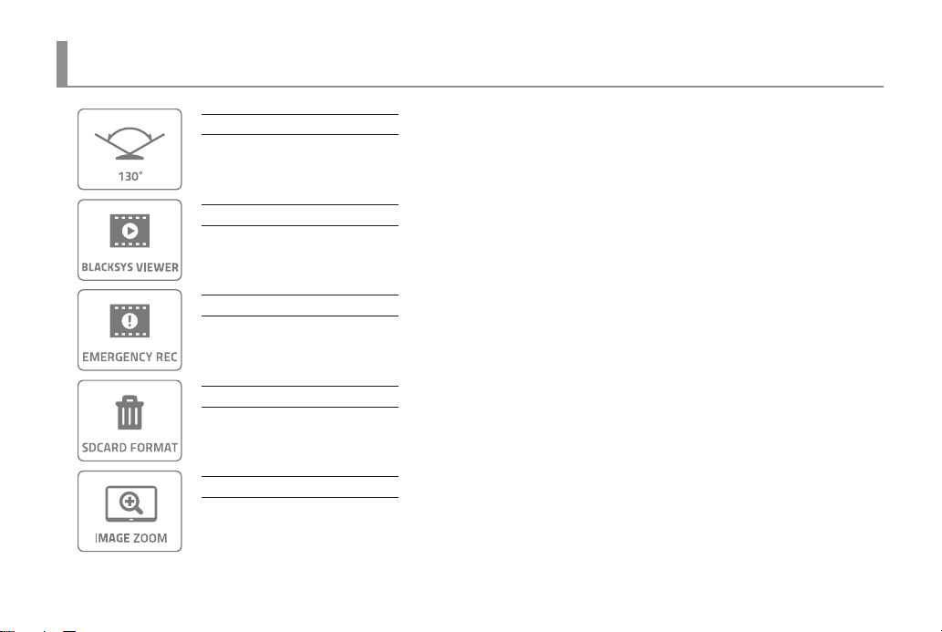
130° Angle of View
130° Diagonal angle lens can record wider angle of view.
Dedicated PC viewer
BlackSys PC viewer provides not only video playback and but also video analysis.
Emergency Button Recording
User can record event manually with emergency button during driving, parking and accident. Recording total 30 sec. including
10 sec. before and 20 sec. after from the time of pressing emergency button is performed. The recorded video at the moment is
stored in event folder
Manual Format
Manual format is available without PC.
Zoom function using PC viewer
Zoom-in the important points of video through PC viewer.
Main features
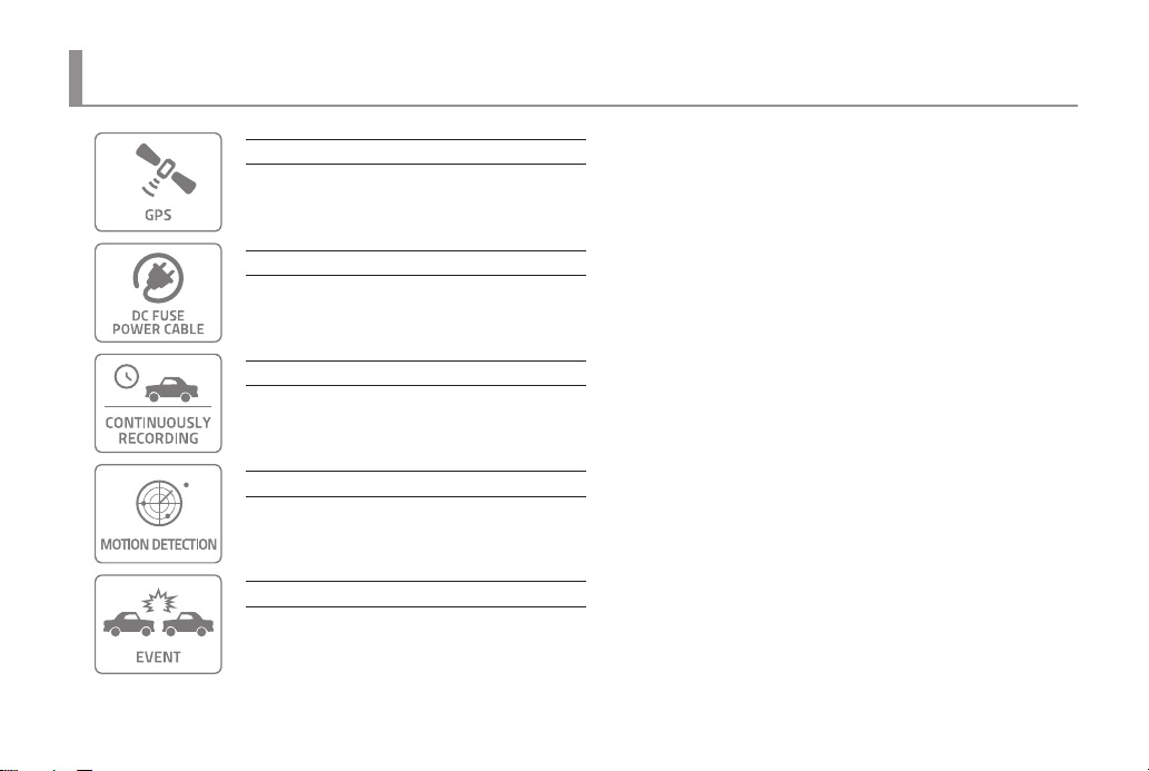
Location and driving information (Optional GPS)
Optional high-sensitive GPS(SiRF 4) records vehicle speed, route and location information. It is synchronized with Google Map
and displays the driving path. It is easy to trace back to the location of the accident using Blacksys PC Viewer.
Video Out (Optional Cable)
If DC fuse power cable is connected, recording is available during parking mode.
Normal Recording
All the images in the driving are recorded continuously as 1 minute le.
If memory is full, recording starts overwriting from the oldest le by deleting them in order.
Motion Detection in Parking Mode
When motion is detected during parking or stopping, recording get started for a certain time and if motion is not detected,
recording is put on standby without recording. This mode stores only necessary videos, SD card memory is managed eciently.
3D G-Sensor
3-axis G-Sensor detects impact, brake, acceleration of vehicle and automatically records video images. To avoid overwriting,
it stores les in a separated folder.
Main features
11
Main features
Main features
12
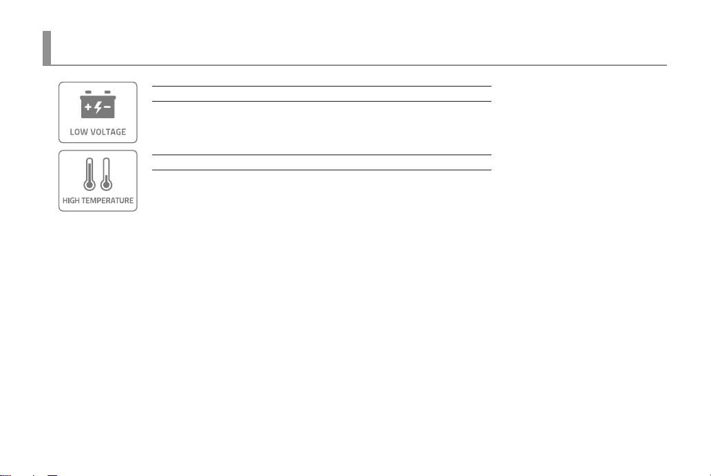
Real-time check and indication of vehicle voltage / Low voltage protection
Since it is possible to check voltage patterns of a vehicle in real time, a user can set up voltage to be suitable for a situation as
well as battery discharge prevention method.
High Temperature Prevention Function
It is a system of which shuts o the black box automatically if the main unit device reaches the temperature which can be strain
to the system and then turns on the black box when temperature decreases to a safe level.
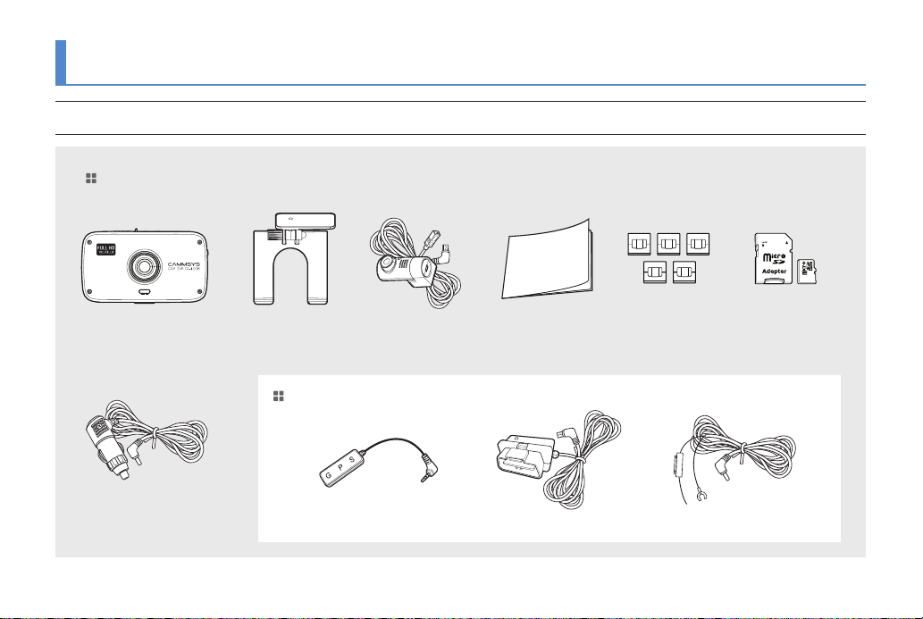
Components
Actual components may be dierent from pictures and some components can be changed in case.
If package doesn’t include below components, please contact a retail shop or company where product was sold.
Standard Components
E
D
I
U
G
R
U
E
S
Main Unit (Device) User Manual Cable Holder Micro SD Memory
Rear CameraHolder
Option
Cigar Jack Cable
(Excluded if OBD is selected)
External GPS modul
OBD terminal
DC Fuse Power Cable
Components
13
Components
14
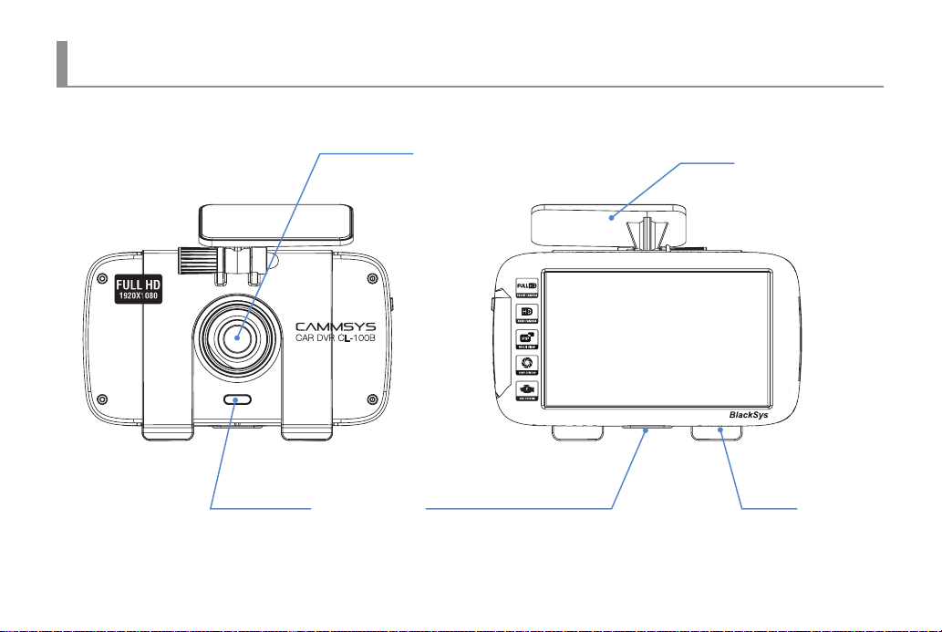
Front & Rear
Camera lens
For video recording
Parking Mode LED
LED indicator for parking or
video recording
Emergency Recording Button
For manual Recording
Holder
Attach the Car DVR to the front window
Speaker
Action state, Voice guide
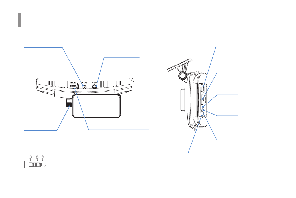
Components
Power Terminal
For supplying power
to the main unit using
cigar jack
Clamping lever
For xing holder to product
and adjustment available on
up/down, left/right side
① GND
② GPS Data
③ Power
GPS Port
For checking location and
speed of vehicle through
dedicated PC viewer
Rear Camera connection port
Mini USB port for HD Rear Camera
OBD LED
Connecting status indicator
OBD Connection Terminal
Check driving information by
connecting OBD cables
Micro SD card slot
External Micro SD card port
OBD
REAR LED
Connecting status indicator
REAR
GPS
REC
GPS LED
OBD
Connecting status indicator
REC LED
Recording status indicator
Up & Right side
15
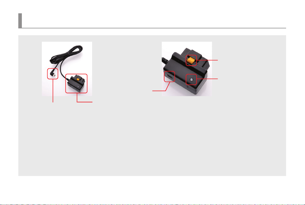
Components of OBD Device (※OBD Optional Components)
Terminal for connecting PCs
(Disable)
Fixed device
Operation Status LED
Black Box Connection Jack
(Permanent power included)
• Black Box Connection Jack : Connection jack which connect with function of OBD terminal (CarNSys) and permanent power.
• Fixed device : A device for fixing a vehicle OBD terminal and an OBD terminal (CarNSys) main device.
• Operation Status LED :
- Blue lighting : Vehicle identification and normal operation status - Blue blinking : Unidentified vehicle
- Red blinking : Defective terminal - Pink blinking : Detection of vehicle malfunction
• Terminal for connecting PCs : Currently disabled
Components of OBD Device
16
Terminal main device

OBD product specication (※OBD Optional Components)
CPU 32 bit Embedded Micro Controller
Memory 4MB Serial Flash
Vehicle I/F CAN, ISO14230(KWP2000), ISO9141-2
Power Terminal Permanent Power (Plug & Play), RTC and Built-in Backup Battery
Black-Box I/F UART (Serial Communication)
PC I/F USB 2.0
Input Voltage DC +8V ~ 24V / 50mA Max, Stand by current of 8mA or less
Operation Tempera-
ture
Dimension (mm) 48mm(W) x 22mm(L) x 24mm(H)
※ For the enhancement of product performance and function, the marked specication is subject to change
and/or modication without notice in advance.
-45°C ~ +85°C
OBD product specication
17

Installation Method
1. Attaching double-sided adhesive tape 2. Installing unit
Wipe up the foreign matters or moisture completely
from the location of installation. Remove the release
paper on double sided tape and attach it
to the cradle part of holder and remove the red
adhesive protector.
Front Camera Installation
18
Installation is recommended on the left/right of room mirror.
Tightly fasten the adhesive of holder to the windshield
by pushing it. Adjust the angle of camera to record forward
and unit to be vertically installed.
Finally, tighten the clamping lever.
※ If a video from navigation system or dashboard reect in windshield,
it could aect video quality.

Installation Method
1. Rear Camera Installation 2. Installation
Connect rear camera to the rear camera connector .
Clean up the cable of Rear Camera from the location
of installation.
Wipe up the foreign matters or moisture completely from the location
of installation. Remove the red adhesive on double sided tape and
attach it to the rear windshield. Installation is recommended on the
middle of rear windshield and holder should be forwarded to the left
side.
※ Tinted windows may cause unclear image of video from rear camera.
Avoid tinted window.
※ An arrow on the picture should point the upper side upon installation.
Rear Camera Installation
19

Installation Method
3. Power cable arrangement and connection 4. Power cable connection and check the LED state
By using the cable holders, arrange the Cigar jack cable and
connect it to the DC IN port(upper hole). Check the recorded
image directly through LCD screen.
※ Power on after connecting rear camera cable.
Rear camera is not recognized if you connect power cable
after connecting rear camera cable.
Rear Camera Installation
20
After inserting the Cigar jack Power cable into cigar jack,
turn on the car ignition. If all LEDs of power status are on,
installation is completed.

Installation Method (※OBD Optional Components)
• Caution for the Installation of OBD
- Turn off the ignition first and then attach this device to a vehicle.
- The installation location is varied over vehicle model so it should be checked in advance.
• In case of installing it to another vehicle
- If this device is installed to another vehicle, it should be installed in the same way as the first installation .
- A vehicle model should be checked first. Then, change the setting upon a vehicle type.
• Installation Location by Vehicle Model
1
2
3
4
SM3 New Model
List of available vehicle
models Reference
(Attachment)
5
SM5 New Model
SM7 New Model
※ OBD terminal of vehicle (It should be attached here.)
OBD Terminal Installation
21

Installation Method (※OBD Optional Components)
OBD Terminal Installation
22
1. Check the location
of an OBD terminal
Check the location of an OBD
terminal of a vehicle for connection
of a device.
3. Fasten
A device may get disconnected due
to long-term vibration so a fastening
device must be properly used.
2. Connect a device
Connect a device and push a fastening
device so it would not get disconnected
4. Organize cables
After organizing cables, connect them
to a black box for usage .

Installation Method (※OBD Optional Components)
※ Installation if the fuse box of a vehicle cannot be closed
1. Separate and Install
If a cover of a fuse box does not
close completely, an OBD terminal
of a vehicle should be separated and
then the device should be installed
3. Attach the Device
Attach the device to the separated
OBD terminal.
After separation, move and then attach
↑
First location of an OBD terminal
2. Separate an OBD terminal
An OBD terminal would be separated
if it gets lifted upward while pushing it.
4. Fasten
Locate the attached device on a
proper place.
Close a cover of a fuse box and then
complete the attachment.
After organizing cables, connect
them to a black box for usage.
OBD Terminal Installation
23

Details on Video Record
Normal, Event, Parking mode recording les are stored and if external SD card is full, overwriting gets started from the oldest le.
Overwriting gets started from the oldest les in order, regular data back-up is required to save important data.
Normal Recording
• Recording starts when vehicle power is turned on and recorded data are stored in SD card(“NORMAL” folder).
Parking Mode Recording
• 5 minutes after park or stop the car, if no motion is detected, it converts to Parking Mode Recording automatically.
(In case of using DC fuse power cable or product is connected with a vehicle battery).
• If motion is detected consistently and driving is resuming, it converts Normal Recording again.
• When it detects impact during Parking Mode(Motion detection), the video file is stored in (“PARK” folder).
Last Scene Recording
• Though power supply is disconnected caused by accident or manually, last scene is recorded and stored by using built-in super capacity battery.
Event Recording
• If Acceleration sensor(G-Sensor) detects impact, sudden unintended acceleration and quick braking or manually pressing the event button during
the car runs, it records 30 sec. of video to the (“EVENT” folder)(10 sec. before and 20 sec. after the event).
※ If power is disconnected within 2 min after power is on, recorded le can be damaged.
Details on Video Record
24

Operating device and instructions
※ Function can be changed according to product upgrade.
Mode Button operation Voice guide
Power
Recording start
GPS
EVENT
Recording
Parking
Mode
Recording
Voice
Recording
OBD Connected
Connected
No connected
Automatic
Manual Pressing Emergency button shortly Sound eect 1
Motion Detection -
ON
OFF
REC
ON
OFF
LED state
REAR GPS REC OBD Parking
X
X
X
X
X
X
X
X
X
X
1CH : recording is starting.
2CH : 2CH recording is starting.
Voice recording is ending.
X
Car DVR is ending.
GPS is connected.
(1 time if connected)
-
Sound eect 1
-
-
OBD is connected.
(Unit of 1 second)
(Unit of 2 seconds)
LED indicator and Voice guide
25

Operating device and instructions
Operate in occurrence of an error
Mode Button operation Voice guide
SD card is not inserted
X
In case of waiting for the insertion: Please
insert a SD card.
LED state
REAR GPS REC OBD Parking
SD card malfunction
Camera error
LED indicator and Voice guide
26
X
X
There is an error on a SD card.
A camera is defective.

LCD Menu - LCD preview screen instruction
Turn On LCD
▶ If CL-100B turns on when power is o, the system starts to operate and a video
recording function gets activated.
▶ The sequence for staring of the CL-100B booting system is as the following.
Booting image → “Video recording start.”→ Video recording screen starts
Video screen
▶ When booting is completed, a real-time video screen would be shown.
▶ Upon 2-channel recording, PIP, displaying an image of a rear camera,
would be shown on the upper right side. If a LCD screen gets touched
after recording, a main menu would appear.
※ If there is no operation after starting the recording, a screen saver would be
shown after 3 minutes.
LCD would be turned o when the screen saver is set as “Disable”.
LCD preview screen instruction
27

LCD Menu - LCD preview screen instruction (※OBD Optional Components)
Preview Screen upon Installation of OBD
▶ OBD icons are composed as the following.
Icon Name Function
In accordance with information received from a
vehicle, a left directional light would be ickered
In accordance with information received from a
vehicle, acceleration pedal information would be
In accordance with information received from
a vehicle, brake pedal information would be
In accordance with information received from a
vehicle, gear transmission P.R.N.D.M information
In accordance with information received from a
vehicle, current speed would be displayed.
In accordance with information received from a
In accordance with information received from a
vehicle, a right directional light would be ickered
along with images.
displayed along with images.
ickered along with images.
would be displayed along with images.
vehicle, current RPM would be displayed
along with images.
※ Displayed information may vary upon vehicle type.
OBD information icon
28
Indication of
Numbers
Indication of
Numbers
Left turn signal
Accelerator Pedal
Information
Brake Pedal
Information
Transmission gear
shift info
Speed(km/h)
RPM
(revolutions per minute)
Right directional
light

LCD Menu - Main Menu
Main Menu
▶ Main Menu Screen is composed as the following.
Icon Name Function
Video recording Move to a screen for video recording.
▶ Indicator
Icon Fuction
1 channel (Front), 2 channel (Front +Rear)
Voice Recording, Stop Voice Recording
Voice Instruction, Mute the Voice Instruction
System information pop-up display
GPS
Video playing
Upgrade
OBD
Conguration
SD card format
Move to a list of which recorded videos can be
Pop-up screen inquiring the rmware update status
Move to a menu screen of which OBD information
Move to a menu for the initialization of time,
system, display, sound and screen saver.
Pop-up screen inquiring whether a SD card is
played.
would be displayed.
could be checked.
formatted or not.
LCD main menu
29

LCD Menu01 : Video recording
Video recording
30
Record Video
▶ It is screen for the execution of video recording. On the upper side, a le name
which is currently being recorded would be shown in after 3 to 5 seconds and
on the upper right side, REC sign would appear.
On the lower right side, a current time would be marked.
▶ When a LCD screen is touched after starting the recording, a main menu would appear.
▶ If there is no operation after starting the recording, a screen saver would be shown
after 3 minutes. If a screen saver is not set, the recording screen would be maintained.
▶ Upon 2-channel recording, PIP, displaying an image of a rear camera,
would be shown on the upper right side.

LCD Menu02 : Video Playing
Video Play List
▶ The video playing screen shows the list of recorded images saved in SD card.
▶ When the “Home” button is clicked on the video playing screen,
it would move to main menu.
▶ If the “Previous” button is clicked on the video playing screen,
it would move to video play list.
▶ When the “ALL/1CH/2CH” button is clicked, all the recorded les would appear
on the list as their sequence, but if the button text is ALL, all the les regardless
of 1CH/2CH would be shown on the list. When the button text is 1CH, only recorded
les of 1CH would appear, and if the button text is 2CH, only recorded les of 2CH
would appear.
▶ “File/Date” Button. If the button text is “File”, a le name shown on the list is the same
as a le name shown on the upper left screen upon recording. If the button text is
“Date”, a le name shown on the list is changed as date.
▶ “Up/Down” buttons would make les to be arranged in an order of date.
▶ File List Navigation Button, upon clicking of “Up/Down” button, a le shown
on the le list is changed. Upon clicking the button once, next/previous ve les
would be shown rather than individual le.
Video Playing
31

LCD Menu02 : Video Playing
Player Screen
▶ Screen to be shown upon selecting the recorded le name at the video player screen.
▶ Upon starting of the playing, the player screen image would be shown
and then disappear after 3 seconds. After disappearing of the playing screen image,
if a LCD screen is touched, the player screen image would appear again.
▶ On the upper side of the player screen, a name of a le which is currently being played
would be shown, and a control button would appear on the bottom.
▶ Player control buttons are composed of the previous button, the play button (stop)
and the next button.
▶ Upon the completion of playing of a current recorded le, the player would play the next le automatically.
▶ If the previous button/next button is clicked during playing, the playing would be stopped immediately and the previous/next le would be played.
If the play button is clicked during playing, the playing would stop and if the playing button is clicked once again, it would resume.
▶ When a LCD screen is touched while the playing is paused, the touched area would get either Zoom In/Zoom Out.
▶ Upon playing of a 2-channel recorded le, a PIP button would be generated and a video recorded by a rear camera would be shown as PIP
on the upper right side. Upon playing of 2 channels, a PIP button would appear on the lower left of a player image, and upon clicking of a PIP button,
the front/rear screen would be switched in the following order. “PIP” → ”Front” → ”Rear ”
Video Playing
32

LCD Menu03 : Firmware Upgrade
Firmware Upgrade
▶ Upgrade le could be easily downloaded from BlackSys website or BlackSys Exclusive
Viewer. Downloaded upgrade le should be copied into a SD card and then the card
should be inserted to the main body. It can be easily updated through LCD.
▶ After copying an upgrade le into a SD card and inserting the SD to a main body
and clicking the rmware update button, a pop up window of “Upgrade le is being
searched” would appear. If there is no upgrade le in SD card, a pop up window
of “No le” would appear. If there is a pop up window of no upgrade le found,
please check whether there is an upgrade le in a SD card or the upgrade le name
is correct.
▶ If an upgrade le is found, a pop up window of “Firmware Update is available.
Continue update??” would appear. If “No” button is clicked, it would go back to
main menu. When “Yes” is clicked, it would be upgraded.
※ Upgrade of an OBD terminal, an optional device, should be executed in the aforementioned sequence.
Firmware Upgrade
33

LCD Menu04 : OBD Main
※ It is a screen to be displayed upon installation of an OBD terminal, an optional device.
Select an OBD System
▶ If an OBD terminal is not installed, an icon would be deactivated.
▶ If an OBD terminal is not corrected or there is an error, a pop up window of showing
a relevant message would appear.
▶ An OBD main menu screen is composed as the following.
Icon Name Function
OBD Main Menu
34
OBD
conguration
Failure check
Engine oil
Trip report
OBD information
Move to a screen for the setup of a vehicle cord and
engine oil exchange distance.
Move to a screen of indicating the vehicle malfunc-
tion diagnosis, coolant temperature and battery
Move to a screen of indicating the remaining dis-
tance from the engine oil exchange distance.
Move to a screen of displaying the driving infor-
mation and eco-driving information received from
Pop-up window showing HW/FW version and
abnormal voltage.
OBD.
current status would appear.

LCD Menu04 : OBD - Conguration and engine oil information screen
Screen for OBD conguration
▶ For the Setup of a vehicle code, an additional vehicle code table would be provide
upon purchase of an OBD product.
Enter a vehicle code corresponding to your vehicle model.
※ Setup of a vehicle code is required once.
▶ Upon clicking of a save button after Setup of a vehicle code, the vehicle code
would be transmitted to an OBD and an OBD menu would appear.
▶ Upon clicking of an “OK” button on the lower left side of a number key pad, a cursor
would move to an enter box. When an arrow button on the lower right side is clicked,
a character typed into the enter box of which a cursor points would be erased.
▶ Setup of engine oil is a function for setup of a distance required for the exchange
of engine oil. Click a number on a number key pad.
▶ Upon clicking of a save button after entering a number, the number would be saved
and an OBD menu would appear.
Screen for Engine oil information
▶ Screen displaying the remaining distance from the engine oil exchange distance.
▶ Along with the remaining distance, an engine oil exchange date would be displayed.
▶ When an “Completed” button is clicked, an engine oil change date would
be changed to a date of which the button is clicked and “Engine oil remain.”
would be reset.
▶ Engine oil remaining distance would be updated after driving and turn o the ignition.
Setup and engine oil information screen
35

LCD Menu04 : OBD - Screen for Malfunction Diagnosis & Trip Report
Screen for Breakdown check
▶ Malfunction Diagnosis information from OBD would be displayed.
▶ It detects information on vehicle malfunctions related with an engine system,
coolant temperature and abnormal battery voltage.
▶ If there is more than one information on engine/mission malfunctions,
the information would be rotated once per second.
▶ Diagnostics of vehicle diagnose errors of Engine sensor (ECU) which is controlled
electronically. Does not diagnose mechanical failure
(puncture of tire, expendables, external damage)
▶ In terms of vehicle maintenance, its point of view can vary, please use it for reference only.
Screen for displaying of a TRIP Report
▶ Information on the driving received from OBD would be displayed.
▶ It is a screen for displaying of driving information, which would appear
when the ignition is o after driving.
▶ Types of information to be displayed would include
- Driving Information : Driving hours, Driving distance, Max. speed, Average speed, Average fuel eciency
- Eco Driving Information : Quick start no., Quick brake no., Idling time, OVER RPM, ECO Point, Overspeed
▶ Average millage can vary with actual fuel expenses, and our product does not
assure this. Use only for reference.
▶ Mileage and speed information may dier from dashboard due to Car maker,
self-correction, and etc.
Screen for Malfunction Diagnosis & Trip Report
36

LCD Menu04 : OBD - Information
Screen for OBD information
▶ It displays versions of hardware and rmware of an OBD terminal.
▶ It displays the operation status of OBD.
The following three messages would be printed out.
“OBD is being normally operated.”
“OBD Boot Error : Please contact a customer service.”
“OBD Normal Error : Please upgrade the terminal.”
OBD information
37

LCD Menu05 : Conguration main menu
Screen for Conguration
▶ Conguration Screen is composed as the following.
Icon Name Function
Time Move to a screen for time Setup.
Conguration main menu
38
System
Display
Sound
Screen Saver
Initialization
Pop-up window for normal, parking shock and cut-
Move to a screen for camera Setup, LCD brightness,
Pop-up window for voice recording and speaker
Pop-up window for selecting a screen saver would
Pop-up window which asks to make return to
o voltage Setup .
and camera brightness Setup menu.
volume Setup would appear.
appear .
default would appear.

LCD Menu05 : Conguration- Time & System Setup
Screen for Time Setup
▶ It is composed of YEAR / MONTH / DAY / HOUR / MINUTE / PM,AM Screen and Home /
Previous, +/-, and Save buttons.
▶ After selecting YEAR / MONTH / DAY / HOUR / MINUTE / PM,AM, the number would
go up/down if +/- button is selected.
▶ When a ‘Save’ button is clicked after setting up of time, the time would be saved.
Screen for System Settings
▶ Normal shock sensitivity and parking shock sensitivity are a menu which would initiate
the recording of an event in occurrence of shock on a vehicle.
▶ Normal shock sensitivity and parking shock sensitivity are composed of low,
normal and high.
▶ Cut-o voltage is a function to complete a black box system when battery voltage
of a vehicle is lower than the set point to prevent the discharge of a battery.
▶ Setpoints for cut-o voltage are divided into 11.9V, 12.0V and 12.1V.
Time & System Setup
39

LCD Menu05 : Conguration - Display menu screen
Screen for Display setup
▶ Displaysetupscreen is composed as the following.
Icon Name Function
▶ Pop-up screens for setup
Display menu screen
40
Camera
LCD brightness It is a screen for setup of LCD brightness.
Camera brightness It is a screen for setup of camera brightness.
It is a screen for setup of frames and resolution of
a camera.

LCD Menu05 : Conguration- Sound
Screen for Sound setup
▶ It is a screen for setup of speaker volume as well as voice recording on/o.
▶ With a voice recording menu, on/o could be selected and speaker volume could be
set to be O/Low/Normal/High.
Sound
41

LCD Menu05 : Conguration - Screen Saver
Screen Saver setup
▶ As for a setup menu, there are O/Clock/OBD.
▶ If “O” is selected, LCD would be turned o automatically to lower the vehicle
battery consumption.
▶ If a Clock is selected, a screen saver image would be changed automatically
in corresponding with time .
※ From 6 am to 5:59.59 pm, an image of green grass would be shown.
From 6 pm to 5:59:59 am, an image of moon would be shown.
※ OBD information display screen saver can be selected only when an OBD terminal,
an optional device, is purchased
Screen Saver
42

LCD Menu05 : Conguration - Initialization
Screen for Initialization
▶ When the initialization button is clicked, a pop-up window of “Would you return
to default” would appear and if “No” is selected, a conguration menu screen would
appear.
▶ If “Yes” is selected, the previous conguration would delete and it would return to default .
Initialization
43

LCD Menu06 : SD Card Format
SD card format
44
Screen for SD card format setup
▶ When a SD card is formatted, it is possible to execute the format of a SD card
within a body.
▶ When a SD card format button image is clicked on a main menu, it would check
whether a SD card is inserted or not. If there is no SD card inserted, a pop-up window
of “Please insert a SD card” would appear.
▶ If a SD card is inserted, a pop-up window for selecting the formatting of a SD card
or not would appear .
▶ If “No” is selected, it would go back to a main menu, and if “Yes” is selected, format
would start and format progress rate would be displayed.
▶ Upon the completion of format, a pop-up window of “Format completion” would
appear and it would go back to a main menu.

PC Viewer instructions
PC Viewer Installation
Insert SD card to the PC or download software from www.
blacksys.co.kr/en > Support > Download and execute .
Once installation is completed, click BlackSys Player and
execute it.
BlackSys Player
Uninstallation
1. Control panel > program uninstallation & change
> uninstall BlackSys Player
2. Execute C:₩Program Files(x86)₩BlackSys₩BlackSys Player
₩Uninstall BlackSys Player
3. Execute Start > All program > BlackSys Player
> Uninstall_BlackSys Player.bat
Recommended System for PC viewer
- OS : Windows XP SP3, Vista(32bit), 7(32/64bit)
- H/W : Pentium 4 2.8GHz over / 1G RAM over
- Web browser : MS Internet Explore 8.0 over
- Direct X ver. : Direct X 9.0(JUNE2010) over
- Other : Windows.NET Framework 3.5 over
PC Viewer instructions
45

PC Viewer instructions
Update
Viewer Screen
Progress bar
Video play speed control
G-Sensor Data Review
OBD data unfold/fold
: Move to Previous File in the List
: Move to 1sec. Before
: Playing video and pause
: Move to 1sec. After
: Move to Next File in the List
: Move to Next Frame
: Volume Control
: Image Brightness Control
PC Viewer Layout
46
Version information
RPM Speed (Km/h)
: Folder open
: Select drive
: Video Screen Capture
: Print
: Conguration
: OBD
: Screen Minimization
: Full Screen / Previous Screen
: Close
Normal : Normal video le list
Event : Event video le list
Parking : Parking Mode video le list
Parking Event : Parking Event video le list
Play list
Map view
: Turn Signal Indicator
: Display an auto transmission
selection lever
BRAKE
: Display a brake
ACCEL
: Display an accelerator
※ If scroll up mouse in front video while it’s playing, video size enlarge 0.2times. Max. 14 times is possible
and total 2.8 times enlarge screen would be available. (1~15 level)
※ PC viewer enlargement(full screen view) : 1~12 level is available in full screen view.

PC Viewer instructions
Drive open
• [ ] Select removable storage device of micro SD card and click “OK”.
• Video files in the selected drive are displayed in time order.
• Select file wish to open and double click in the file list
[ ] or click play icon for the video play.
Select Folder
• [ ] Select folder open icon and select folder wish to open in the folder search window. Click “OK”.
Basic use
47

PC Viewer instructions
※ Applying Setting : Save the conguration PC Viewer -> Put SD card into CL-100B -> Reboot the device.
Conguration
48
Conguration
Voice recording
Speaker
Normal shock sensitivity
Parking shock intensity
Cut-o voltage Setup
Entry time
Parking LED
Time zone
Frame Setup
Resolution Setup
Camera brightness Setup
LCD brightness Setup
Screen saver
Save
Default value
: OFF / ON
: O / Low / Normal / High
: Low-Normal-High
: Low-Normal-High
: 11.9V / 12.0V / 12.1V
: OFF / 5min / 10minmin / 20min / 30min
: OFF / ON
: GPS Time zone set up
: 15 / 25 fps
: HD / Full HD
: Dark / Normal / Bright
: Dark / Normal / Bright
: OFF / Clock / OBD
: Save Setup le to SD card
: Return to default

PC Viewer instructions
TRIP report
▶ If an OBD trip report button on the upper side is clicked,
the following screen on the left would appear.
▶ If you double click a le on a trip report le list on the upper left,
a report value would appear.
- Engine On/O : Driving start time and end time
- Select folder : Select Trip report le folder
- Driving hours : Hours from the start to the end
- Driving distance : Distance from the start to the end
- Max. speed : Maximum speed during the driving hours
- Average speed : Average speed during the driving hours
- Accumulated distance : Accumulated distance of a vehicle
- Accumulated fuel volume : Accumulated fuel amount of a vehicle
- No. of quick start : No. of quick start during the driving hours
- No. of quick brake : No. of quick brake during the driving hours
- Idling time : Idling hours during the driving hours
- OVER RPM : No. of Over RPM during the driving hours
- Overspeeding time : Over Speeding hours during driving hours
- Unplug, Plug Date/Time : OBD terminal separation/attachment hours
- Fuel cut millage : Accumulated distance in inertia driving
caused by discontinuance of fuel supply
- ECO point : ECO driving score based on report value
- ECO millage: ECO driving accumulated score
- Eco driving time : No. of hours in economic driving
- Fuel cut time : Hours in inertia driving caused by discontinuance of fuel
TRIP report
49

Firmware Update
Firmware Update
Please follow the below process in case of updating rmware.
① Remove SD card from the unit.
• Turn off the ignition first and remove cigar jack cable from the unit.
② Access our webpage(www.blacksys.co.kr > Support > Download) and download the latest update file.
③ Connect SD card to PC and paste downloaded latest update file(CF100update.tar) to the root of removable disk.
④ Insert SD card which contains latest update file to the unit.
• Turn on the ignition and connect cigar jack cable to the unit.
⑤ Touch the LCD screen and enter a main menu mode, and then click a firmware update button to upgrade.
• Do not disconnect power cable while update is in process. It can cause malfunctioning.
※ Please check notice before upgrading firmware as firmware upgrade may change some functions of the product.
Firmware Update
50

How to format SD card
Check the virus and format the SD card in a regular basis (twice a month at least) to avoid disadvantage caused by storage error such as non-recording and abnormal recording.
PC format
① Insert or connect SD card to PC.
② Click [Start] → [My Computer]
③ Place mouse pointer on [Portable USB drive] SD card and click the right button of mouse. then click the [Format].
④ Once click the [Start] button, format is started.
• FAT 32 format is required if SD card recognition and record error happen.
• Change SD card if PC doesn’t recognize SD card or format is not able to be completed.
• If SD card contains other data, it can cause malfunctioning. Therefore, please remove it.
※ As SD card is expendable supply, manufacturer is not responsible for any data loss and damage. Also, manufacturer cannot guarantee the recorded data in SD card.
How to format SD card
51

Technical Specication
Model Name CL-100B
Camera
Function
Display
Temperature
Power Input Voltage DC 12V ~ 24V (±0.3V ) / CIGAR JACK CABLE
Technical Specication
52
Lens (Pixel) Front : 2M Pixels, Rear: 1M Pixels
Angle of View Front : 130° / Rear: 120°
Sensitivity (Intensity of Illumination) 1.0 LUX
Video Encoding / Voice Encoding H.264(AVI) / PCM
Resolution Front : 1920(H)x1080(V) Full HD, Rear : 1280(H)x720(V) HD
Normal Recording NORMAL (70% of memory space, 1min./le, 30 frame/s)
Recording Options
Rec. Method (Video Recording) In case SD Card is full, it deletes the oldest les (automatically) in order
Voice Recording Built-in MIC records voice and surround sound
Format Micro SD Card Format
External GPS SiRF 4(Option)
Shock Sensor Tri-axial shock detection G-Sensor
Memory Storage Memory Storage Micro SD Card (16G ~ 32G)
Rec. Frame Max. 25fps
Low Voltage Protection Built-in
High Temperature Protection Built-in
Embedded LCD (Built-in LCD) 4.0 Inch panorama (wide viewing angle) LCD
Video Playing Car DVR LCD and Exclusive PC Viewer Program
Video Analysis Video Analysis through PC Viewer software
Operation temperature -20°C ~ 70°C
Storage temperature -30°C ~ 80°C
Dimension(mm) 120mm(W) x 168mm(L) x 35mm(H)
Weight 168g
※ Technical Specication can be changed without prior notice for product improvement..
EVENT (20% of memory space, 30sec./le, 30 frame/s)
Auto Parking Mode (1min./le, 30frame/s)

Customer Service
We don’t take any responsibility for the data loss during the service. Please back up the date before applying for service.
CammSys Customer Service
- Address : 3F Daeil B/D, 681-17, Yeoksam-dong, Gangnam-gu, Seoul, 135-081 Korea
- Opening hour: 09:00 ~ 18:00 (Mon. ~ Fri.)
- Closed : Saturday, Sunday, and Public Holiday
If you come to customer service center, service personnel will care for the service timely and properly.
For further information regarding customer service, please refer to www.blacksys.co.kr/en.
Customer Service
53

Warranty
We provide product repair and replacement services within the warranty period
in accordance with t he consumer protection reg ulations(the Korea Fair Trade Commission Directive 2008-3)
Warranty period
• Product(main unit): 12 mo nths from the purchase date(But, if purchase date is not clear, it can be applying 3 months warranty after manufacturing date)
• Accessory(expendable supply) : 6 months including SD card.(In case of using DC fuse power cable, memory card life can be shorter than general use)
• Service parts holding period: 5 years after stopping sales
Type of Damage
Claim a service for a main part within 10 days after purchase Replacement or refund Not applicable
Claim a service for a main part within 1 month after purchase Replacement or Free repair Not applicable
Claim a service for trouble
caused in a normal use
condition
Claim a service for not
holding service parts within
service parts holding period
Damaged unit from distribution Replacement Not applicable
Damaged unit from installation Replacement Not applicable
Customer’s negligence or
fault, Functional defect
※ Warranty period is 12 months after purchase.
※ We provide product repair and replacement services within the warranty period in accordance with the consumer protection regulations.
(the Korea Fair Trade Commission Directive 2008-3)
Warranty
54
Claim a service for faulty unit Free repair Repair at cost
Repair is not available Replacement or refund Replacement or refund after depreciation
Replacement is not available Refund at cost Applicable by bylaw
Claim a service for a main part within 1 month after unit exchange Refund at cost Applicable by bylaw
Same defect over 3 times Replacement or refund Not applicable
Multi defect over 5 times Replacement or refund Not applicable
Lost by service center during repair service Replacement or refund Applicable by by law
Trouble caused in a normal use condition Replacement or refund
Customer’s negligence or fault, functional defect Repair at cost
Repair is available Replacement at cost Applicable by bylaw
Repair is not available Repair at cost Repair at cost
Within Warranty Period After Warranty Period
Compensation standard
Not applicable

Product Warranty
Model Name CL-100B
Manufacturer Cammsys Co.,Ltd
Serial No.
Purchase Date
Warranty Period 12 months from the purchase date
Name Tel .
Customer Information
Address
Assembler information Shop name Tel .
※ The warranty for the product is beneted by the details on the warranty card.
※ Warranty period is counted from the purchase date. So get the purchase date.
※ This warranty card is not reproduced.
(But, if purchase date is not clear, it can be applying 3 months after manufacturing date)
Product Warranty
55

Daeil Bldg 3F, 681-17, Yeoksam-dong, Gangnam-gu, Seoul, Korea
Tel. 070-4680-2595 / Fax. 070-8668-1161 / www.cammsys.net / www.blacksys.co.kr/en
m.0.1.0.e
 Loading...