

Page 1
MODEL:
ENGLISH
v05
OWNER’S MANUAL
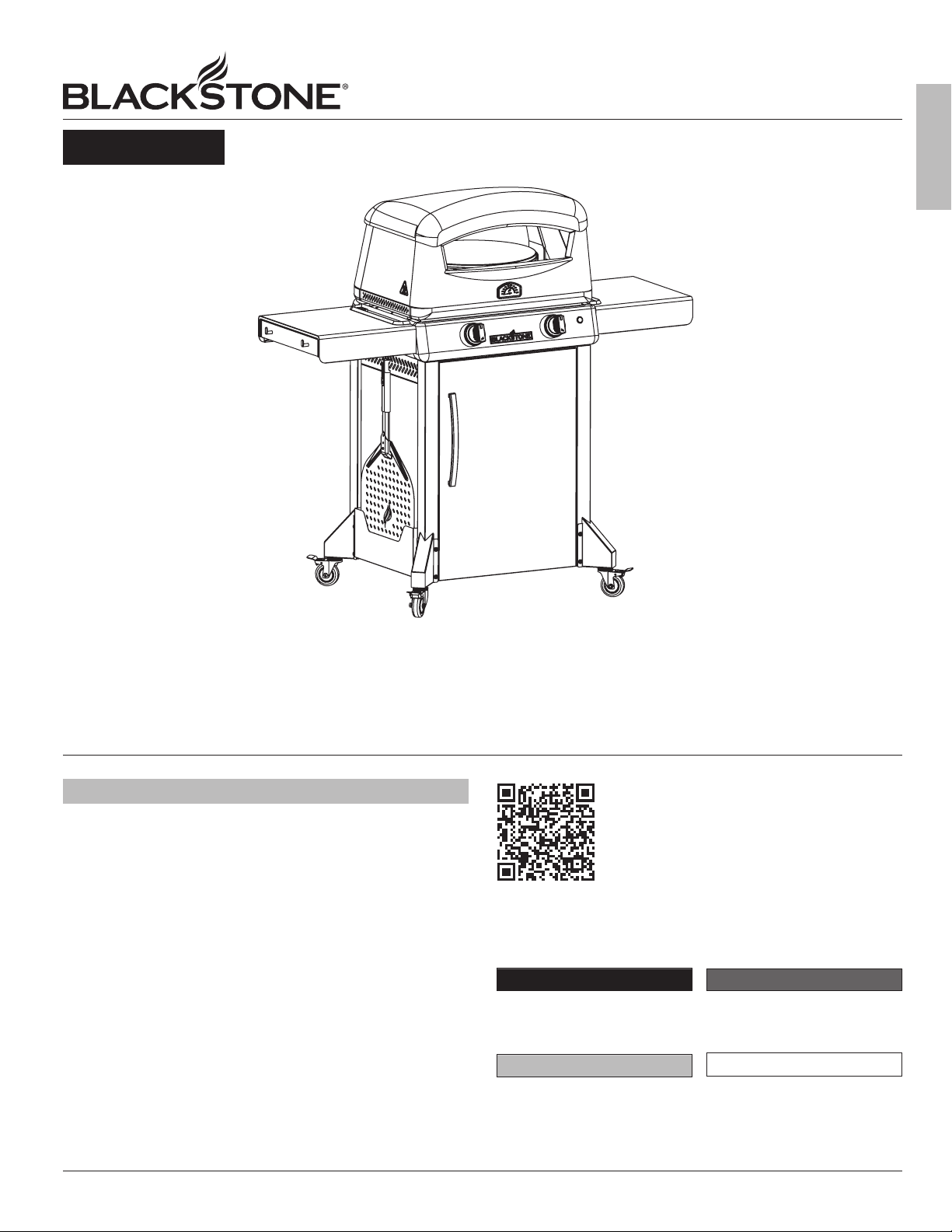
PIZZA OVEN
WITH MOBILE CART & SIDE SHELVES
TABLE OF CONTENTS
IMPORTANT SAFETY INFORMATION . . . . . . . . . . . . . . . . . . . . . . .
CUSTOMER SUPPORT . . . . . . . . . . . . . . . . . . . . . . . . . . . . . . . . . . . . . . . . .
ASSEMBLY GUIDE . . . . . . . . . . . . . . . . . . . . . . . . . . . . . . . . . . . . . . . . . . . . . .
USING YOUR BLACKSTONE . . . . . . . . . . . . . . . . . . . . . . . . . . . . . . . . . . .
TROUBLESHOOTING . . . . . . . . . . . . . . . . . . . . . . . . . . . . . . . . . . . . . . . . . . . .
IMPORTANT:
This instruction manual contains important
information necessary for the proper assembly and safe
use of the appliance.
Read and follow all warnings and instructions before
assembling and using the appliance.
Follow all warnings and instructions when using
the appliance.
Keep this manual for future reference.
Installer/Assembler: Leave these instructions with the consumer.
SAFETY ALERT KEY
DANGER
Indicates a hazardous situation
that, if not avoided, will result in
death or serious injury.
CAUTION
Indicates a hazardous situation
that, if not avoided, could result
in minor or moderate injury.
For the latest version of this manual,
scan this code or visit
BlackstoneProducts.com/support
WARNING
Indicates a hazardous situation
that, if not avoided, could result
in death or serious injury.
NOTICE
Indicates information considered
important, but not hazardrelated (e.g. messages related to
property damage).
BLACKSTONEPRODUCTS.COM/SUPPORT
| CONTACT CUSTOMER SUPPORT BEFORE RETURNING APPLIANCE TO RETAILER.
Page 2
OWNER’S MANUAL | IMPORTANT SAFETY INFORMATION
IMPORTANT SAFETY INFORMATION
MODEL: 6831
DANGER
If you smell gas:
ENGLISH
• Shut o gas to the appliance.
• Extinguish any open flame.
• Open hood (if applicable).
• If odor continues, keep away from the appliance
and immediately call your gas supplier or your fire
department.
Failure to follow these instructions could result in fire or
property damage, personal injury or death.
DANGER
• NEVER operate this appliance unattended.
• If a fire should occur, keep away from the appliance and
immediately call your fire department. DO NOT attempt
to extinguish an oil or a grease fire with water.
Failure to follow these instructions could result in fire or
property damage, personal injury or death.
ELECTRIC APPLIANCE SAFETY
TO PROTECT AGAINST ELECTRIC SHOCK:
• DO NOT immerse cord or plugs in water or other liquid.
• Unplug from the outlet when not in use and before cleaning. Allow
to cool before putting on or taking o parts.
• DO NOT operate this appliance with a damaged cord, plug, or after
the appliance malfunctions or has been damaged in any manner.
Contact the manufacturer for repair.
• DO NOT let the cord hang over the edge of a table or touch
hot surfaces.
• Keep any electrical supply cord and the fuel supply hose away from
heated surfaces.
• When connecting, first connect plug to the appliance then into
the outlet.
WARNING
• DO NOT store or use gasoline or other flammable liquids
or vapors in the vicinity of this or any other appliance.
• An LPG cylinder not connected for use shall not be
stored in the vicinity of this or any other appliance.
GAS APPLIANCE SAFETY
• The use of alcohol, prescription, or non-prescription drugs may
impair the consumer’s ability to properly assemble or safely
operate the appliance.
• Keep children and pets away from the appliance at all times.
• Have a type BC or ABC fire extinguisher readily available.
DO NOT USE FOR PURPOSES OTHER THAN INTENDED.
• For outdoor domestic use only, not for commercial use.
• DO NOT use this appliance as a heater.
WARNING
Improper installation, use, adjustment, alteration, service,
modification, or maintenance can cause injury or property
damage. Refer to this manual.
INSTALLATION MUST CONFORM WITH LOCAL CODES.
In the absence of local codes, installation must conform with
ANSI Z223.1/NFPA 54, CSA B149.1, or CSA B149.2.
either
BLACKSTONEPRODUCTS.COM/SUPPORT
Page 3
(The Manufacturer Label is a large silver sticker found on the body of your
appliance.)
������������������������������������������
��������������������������
���������������������������������
����������������������������������������
��������������������������������������
����������������������������������
���������������������������������������
���������������������������
������������������������������������
��������������������������������������
����������������������������������������
����������������������������������������
��������������������������
������������������������������������������
�����������������������������
����������������������������������
�����������������������������������������
����������������������������������������
������������������������������������������
����������������������������
����������������������������
����������������������������������������������������
�������������������������������������������������
��������������������������������
���������������������������������������
���������������������������������������������������
����������������������������������������������������
������������������������������������������������������
��������������������������������
��������������������������������������������
��������������������������������������������������
�������������������������������������������������
������������������������������������������������������
��������
����������������������������������������������������
����������������
����������������
����������������
����������������
�����������������������������������
����������������
������������������������
��������������������������������
��������������������������������
MODEL: 6831
| OWNER’S MANUALCUSTOMER SUPPORT
CUSTOMER SUPPORT
CONTACT US THREE YEAR WARRANTY
Visit us online at BlackstoneProducts.com/support
for assistance concerning appliance use, replacement parts, or
your warranty.
CUSTOMER SUPPORT HOURS:
Monday – Friday
7:00 am – 5:00 pm (Mountain Time Zone)
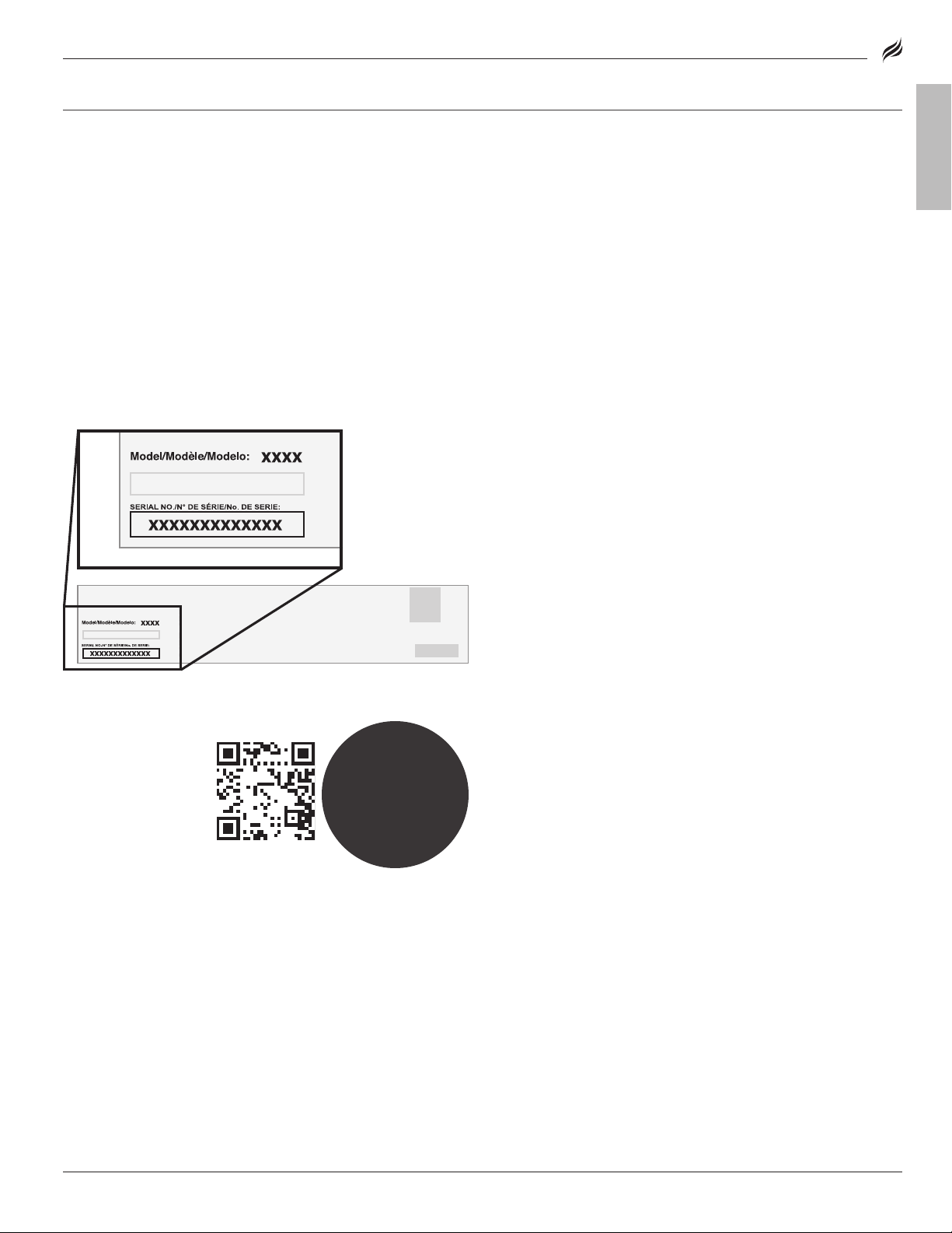
SERIAL NUMBER LOCATION
To enable your warranty, you will need to provide your appliance’s
Serial Number.
The Serial Number can be found on your appliance’s
Manufacturer Label.
(The Manufacturer Label is a large silver sticker found on the body of your
appliance.)
☞
�����������������������������������
����������������
������������������������
��������������������������������
��������������������������������
������������
������������
����������������������������
����������������������������������������������������
�������������������������������������������������
��������������������������������
���������������������������������������
���������������������������������������������������
����������������������������������������������������
������������������������������������������������������
��������������������������������
��������������������������������������������
��������������������������������������������������
�������������������������������������������������
������������������������������������������������������
��������
����������������������������������������������������
������������������������������������������
��������������������������
���������������������������������
����������������������������������������
��������������������������������������
����������������������������������
���������������������������������������
���������������������������
������������������������������������
��������������������������������������
����������������������������������������
����������������������������������������
��������������������������
������������������������������������������
�����������������������������
����������������������������������
�����������������������������������������
����������������������������������������
������������������������������������������
����������������������������
FREE
ECOOKBOOK
WHEN YOU REGISTER
��������
��������
��������
��������
��������
����������������
����������������
����������������
����������������
ENGLISH
North Atlantic Imports, LLC warrants this product against defects
in materials and workmanship for a period of three (3) years from
the original date of purchase under normal use. To the extent any
such defects occur, North Atlantic Imports, LLC, in its discretion, will
provide the appropriate replacement part(s) at no charge.
In no event shall North Atlantic Imports, LLC be liable for consequential, indirect or incidental damages resulting from the installation,
use or failure of the product.
This warranty DOES NOT cover:
• Inspection costs or labor for replacement of any defective part(s);
• Cosmetic defects which DO NOT aect product performance or
integrity;
• Normal wear and tear;
• Damage due to vandalism; acts of nature, including but not limited
to wind, storms, hail, floods;
• Improper assembly, installation, or use;
• Discoloration or fading of the finish as a result of exposure to chemicals, spills, pool or salt water;
• Corrosion/ rust.
This product has been designed for safety and quality. Any modifications made to the original product could compromise its structural
integrity or function and could lead to product failure or personal
injury. As such, modifying this product voids all warranties.
This product is for RESIDENTIAL USE ONLY, and is not for commercial,
contract or other non-residential purposes. North Atlantic Imports,
LLC disclaims all other representations and warranties of any kind,
express or implied.
The warranty applies to the original purchaser and is non-transferable. It does not apply to accessories or parts not supplied with
the product, to purchases of display models, or to product that is
sold on clearance or “as is”. You may, however, have other specific
legal rights based on the laws of your specific state or country of
residence.
To activate your warranty, register your product at
BlackstoneProducts.com/register
North Atlantic Imports, LLC reserves the right to change or modify
this warranty at any time.
BLACKSTONEPRODUCTS.COM/SUPPORT
Page 4
OWNER’S MANUAL | ASSEMBLY GUIDE MODEL: 6831
PARTS
1.1b
Nameplate
Control knob bezels
Control knobs
Burner box surround
Burner connecting
Burner box bottom
PARTS
1.3c
Burner insulation
Burner bottom panel
Oven body surround
Oven door seat
Thermometer
PARTS
1.5a
Oven body bottom
Burner head support
Upper pizza chamber
Lower pizza
Fire bale panel
Ignitor
PARTS
1.8a
Burner A
Burner B
Gas line and regu-
Safety valve thermo-
Ignition needle A
Ignition needle B
Wing screw
ASSEMBLY GUIDE
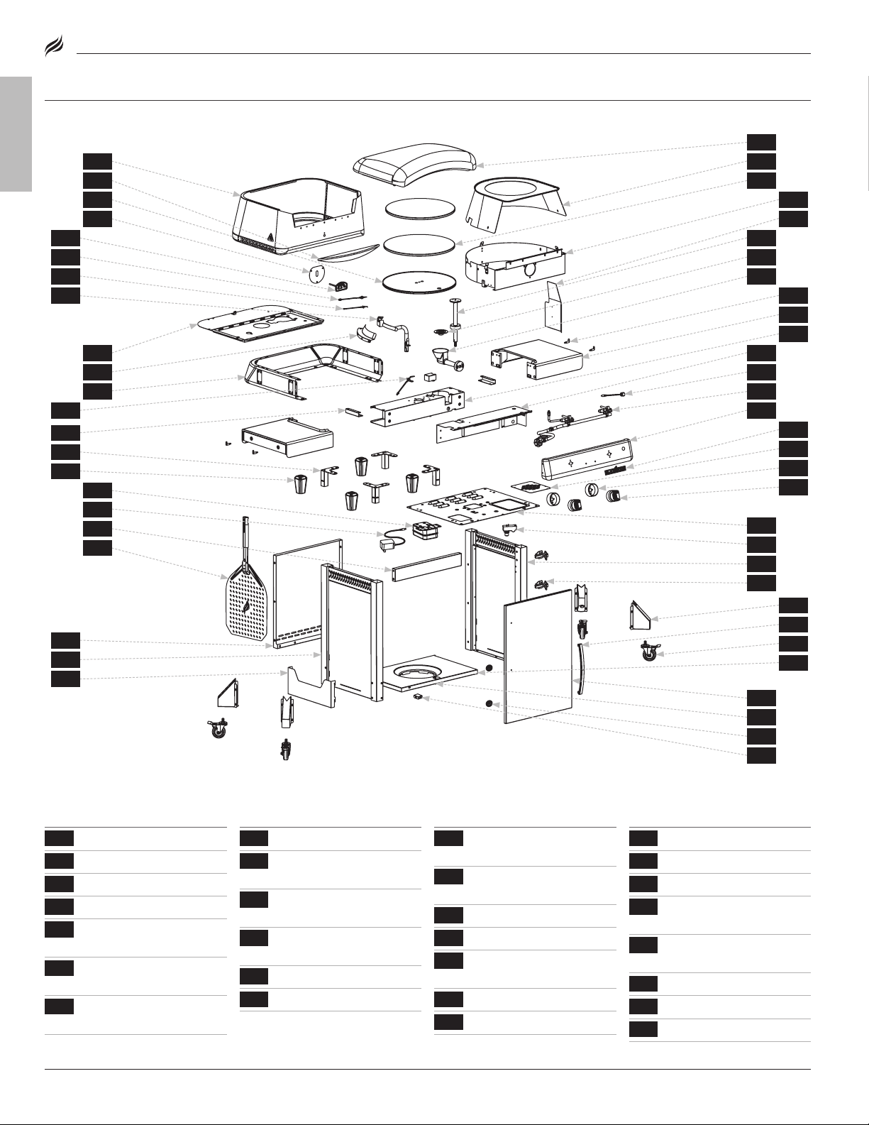
ExPLODED VIEW
ENGLISH
1.4c
1.9b
1.9d
1.8b
1.9c
1.2b
12
11
21
22
16
1.4b
10
1.4d
1.5a
1.5b
1.2a
6
5
24
15
2
1.6a1.4a
4
1.6b
1.6c
7
8
1.8a
14
13
1.3b
1.3c
1.7b
1.9a
1.1a
1.1b
1.3b
1.1c
1.1d
1.3a
1.7a
23
19
26
18
25
3
17
3.1
20
9
PARTS LIST
1.1a
Control panel
1.1c
1.1d
1.2a
panel
1.2b
plates
1.3a
panel
QTY
1.3b
Burner base panel
panel
1.3d
plate
1.4a
panel
1.4b
1.4c
QTY
1.4d
Thermometer heat
shield
panel
1.5b
1.6a
1.6b
chamber
1.6c
1.7a
QTY
1.7b
Motor button
1.8b
1.9a
lator assembly
1.9b
couple
1.9c
1.9d
3.1
BLACKSTONEPRODUCTS.COM/SUPPORT
QTY
Page 5
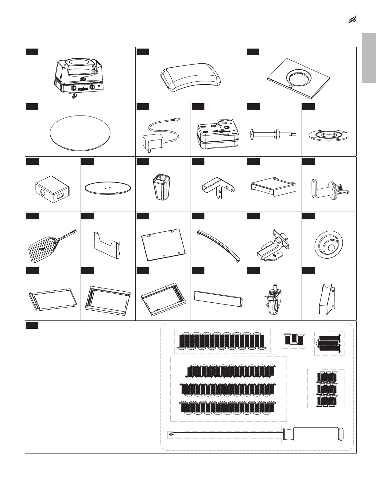
1
Oven body (1 piece)
2
Oven lid (1 piece)
3
Cart base (1 piece)
| OWNER’S MANUALASSEMBLY GUIDEMODEL: 6831
ENGLISH
4
Pizza stones (2 pieces)
9
Limiter (1 piece)
15
Pizza peel
(1 piece)
21
Rear cart panel
(1 piece)
10
Turntable
(1 piece)
16
Pizza peel
holder (1 piece)
22
Left cart panel
(1 piece)
5
Power cord
(1 piece)
11
Feet (4 pieces)
17
Door panel
(1 piece)
23
Right cart panel
(1 piece)
6
Motor (1 piece)
12
Legs (4 pieces)
18
Door handle
(1 piece)
24
Front cart panel
(1 piece)
7
Rotating shaft
(1 piece)
13
Side shelves
(2 pieces)
19
Hinges
(2 pieces)
25
Caster wheels
(4 pieces)
8
Bearing bracket
(1 piece)
14
Side shelf hooks
(4 pieces)
20
Handle sleeves
(2 pieces)
26
Wheel brackets
(4 pieces)
27
Hardware pack (1 piece)
a. M6x14 black screws (17 pieces)
b. M6x12 screws (56 pieces)
c. M6x12 countersunk screws (3 pieces)
d. M6x18 screws (3 pieces)
e. M4x12 countersunk screws (18 pieces)
f. Phillips head screwdriver (1 piece)
BLACKSTONEPRODUCTS.COM/SUPPORT
[f.]
[a.]
[b.]
[c.]
[d.]
[e.]
Page 6
OWNER’S MANUAL | ASSEMBLY GUIDE
NOTICE
Place appliance on a heat-resistant and flame-resistant
surface while in use.
TOOLS NEEDED:
#3 Phillips head screwdriver &
Adjustable wrench
TOOL NEEDED:
#3 Phillips head screwdriver
TOOL NEEDED:
Adjustable wrench
TOOL NEEDED:
5mm Allen wrench
Size: 18 x 12 in (45 x 30 cm), 20 lb (9 kg)
LPG cylinder must include collar to
protect LPG cylinder valve.
NOT INCLUDED:
AA battery
NOT INCLUDED:
LPG cylinder
Size: 4 x 8 in (10 x 20 cm), 1 lb (453 g)Size: 4 x 8 in (10 x 20 cm), 1 lb (453 g)
NOT INCLUDED:
One (1) AA battery (for ignition)
Optional four (4) AA batteries
(for the motor)
TOOL NEEDED:
5mm Allen wrench
CAUTION
Heavy pieces. Two people should assemble this appliance.
NOTICE
Place appliance on a heat-resistant and flame-resistant
surface while in use.
CAUTION
Hot appliance. The cover/lid/hood (as applicable) MUST be
open/removed when the appliance is in use.
ASSEMBLY INSTRUCTIONS
Find a large, clean area to assemble your appliance.
ENGLISH
Remove all packing material before assembling.
CAUTION
Sharp edges. Wear gloves while assembling.
CAUTION
Heavy pieces. Two people should assemble this appliance.
NOTICE
• DO NOT mix old and new batteries.
• DO NOT mix alkaline, standard (carbon-zinc) or rechargeable
(ni-cad, ni-mh, etc.) batteries.
NOT INCLUDED:
LPG cylinder
Size: 18 x 12 in (45 x 30 cm), 20 lb (9 kg)
LPG cylinder must include collar to
protect LPG cylinder valve.
MODEL: 6831
NOT INCLUDED:
One (1) AA battery (for ignition)
Optional four (4) AA batteries
(for the motor)
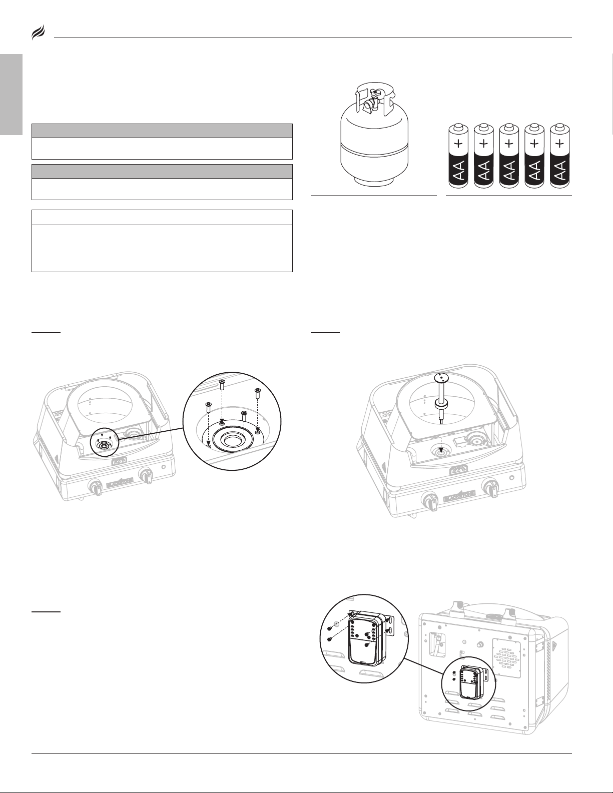
STEP 01
Place the oven base on a smooth flat surface.
Use four (4) M4x12 countersunk screws [e.] to attach the bearing
bracket to the oven floor.
STEP 03
Use four (4) M6x14 black screws [a.] to attach the motor to
the underside of the burner box.
Note: Ensure that the rotating shaft is aligned before tight-
ening screws.
STEP 02
Insert the rotating shaft through the bronze sleeve and into
the bearing bracket.
BLACKSTONEPRODUCTS.COM/SUPPORT
Page 7
| OWNER’S MANUALASSEMBLY GUIDEMODEL: 6831
Push to lockPush to lock
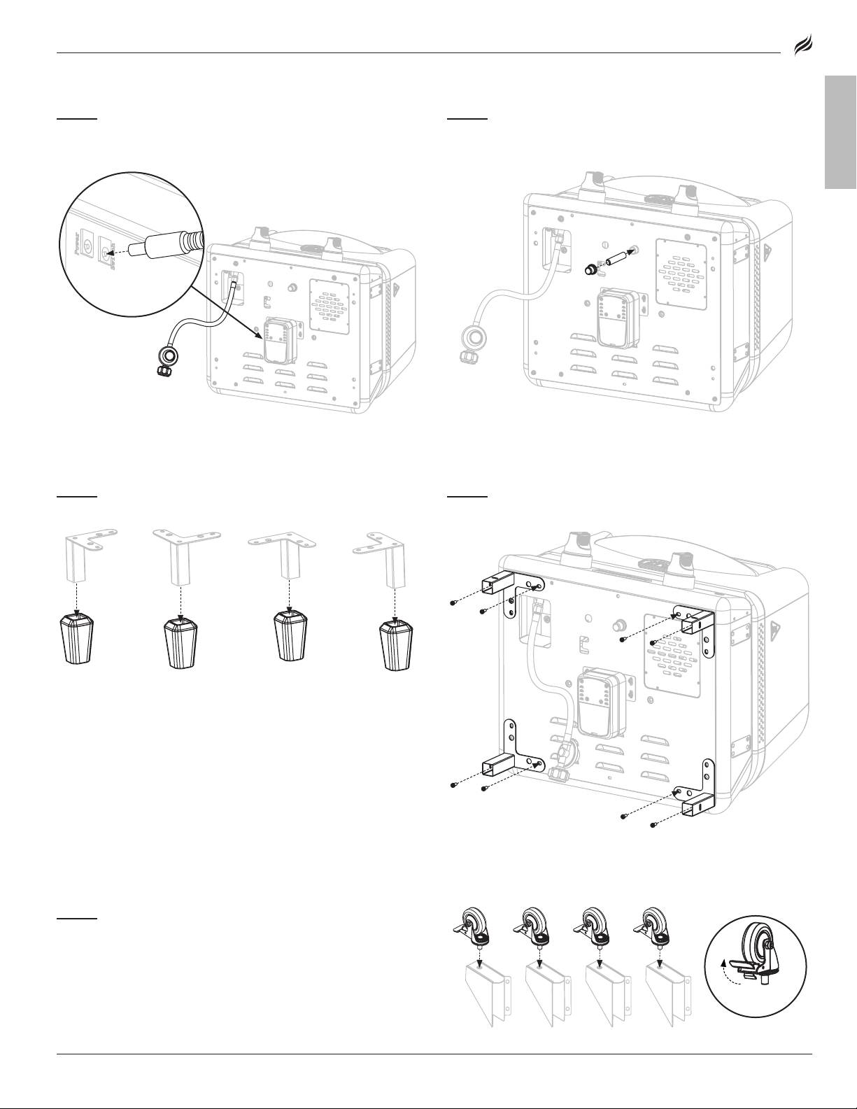
STEP 04
Pull the regulator and switch cable out of the base
(cut zipties).
Plug the switch cable into the motor.
STEP 06
Remove the feet from the legs.
STEP 05
Insert one (1) AA battery (not included) under the
battery cap.
Screw the cap into place over the positive terminal.
STEP 07
Use eight (8) M6x14 black screws [a.] to attach the four (4)
legs to the underside of the burner box.
ENGLISH
STEP 08
Screw the four (4) caster wheels into the bottom of the four
(4) wheel brackets. (Ensure that the wheels are locked.)
BLACKSTONEPRODUCTS.COM/SUPPORT
Page 8
OWNER’S MANUAL | ASSEMBLY GUIDE MODEL: 6831
Front of the cart
Front of the cart
Front right hinge
holes
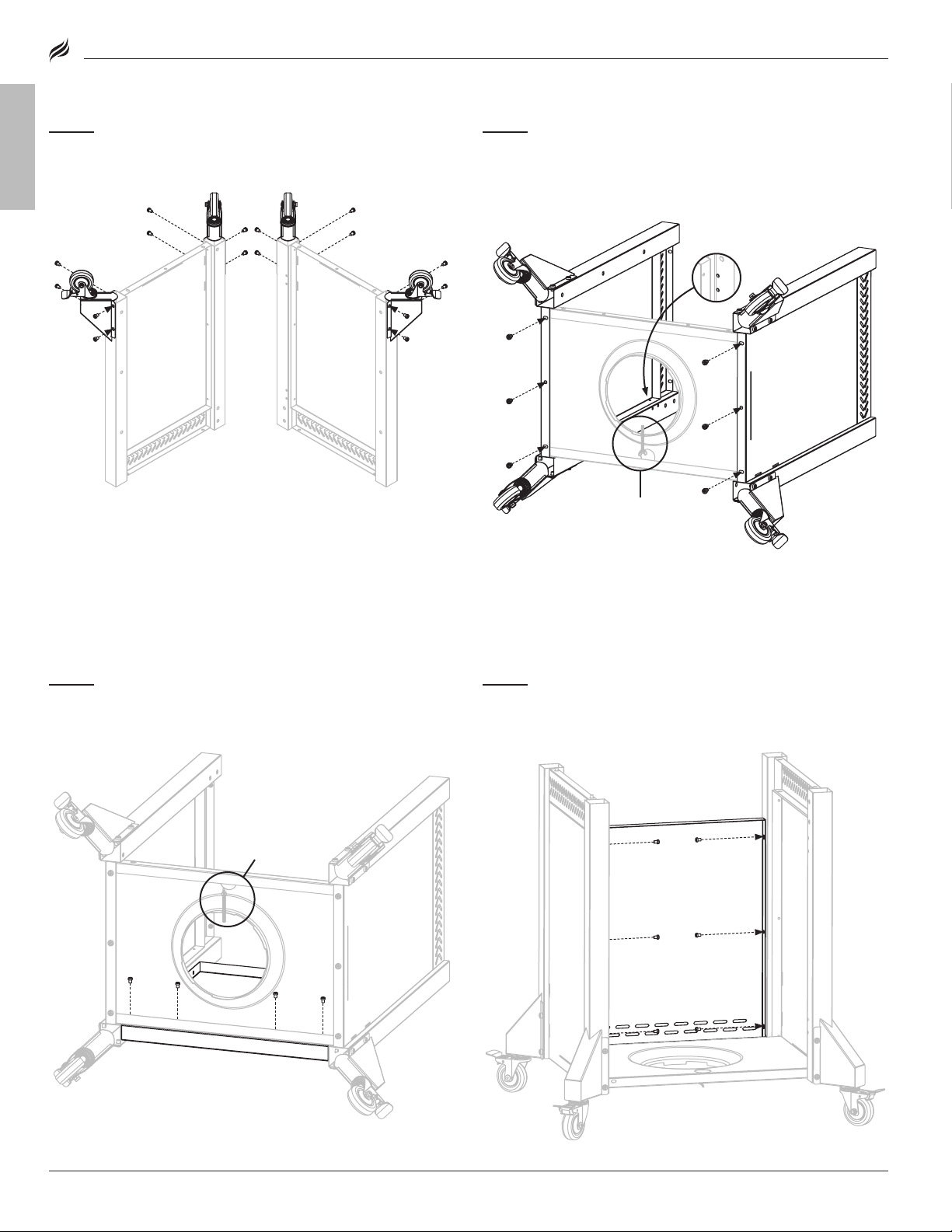
STEP 09
Use eight (8) M6x12 screws [b.] to attach two (2) wheel
assemblies to the left cart panel.
Repeat with the right cart panel.
ENGLISH
STEP 10
Use three (3) M6x12 screws [b.] to attach the right cart panel
to the cart base.
Repeat with the left cart panel.
Note: DO NOT fully tighten screws yet.
Front of the cart
Front right hinge
holes
STEP 11
Use four (4) M6x12 screws [b.] to attach the rear cart panel to
the cart base.
Note: DO NOT fully tighten screws yet.
Front of the cart
STEP 12
Use six (6) M6x12 screws [b.] to attach the rear cart panel to
the left and right cart panels.
Note: DO NOT fully tighten screws yet.
BLACKSTONEPRODUCTS.COM/SUPPORT
Page 9
| OWNER’S MANUALASSEMBLY GUIDEMODEL: 6831
STEP 13
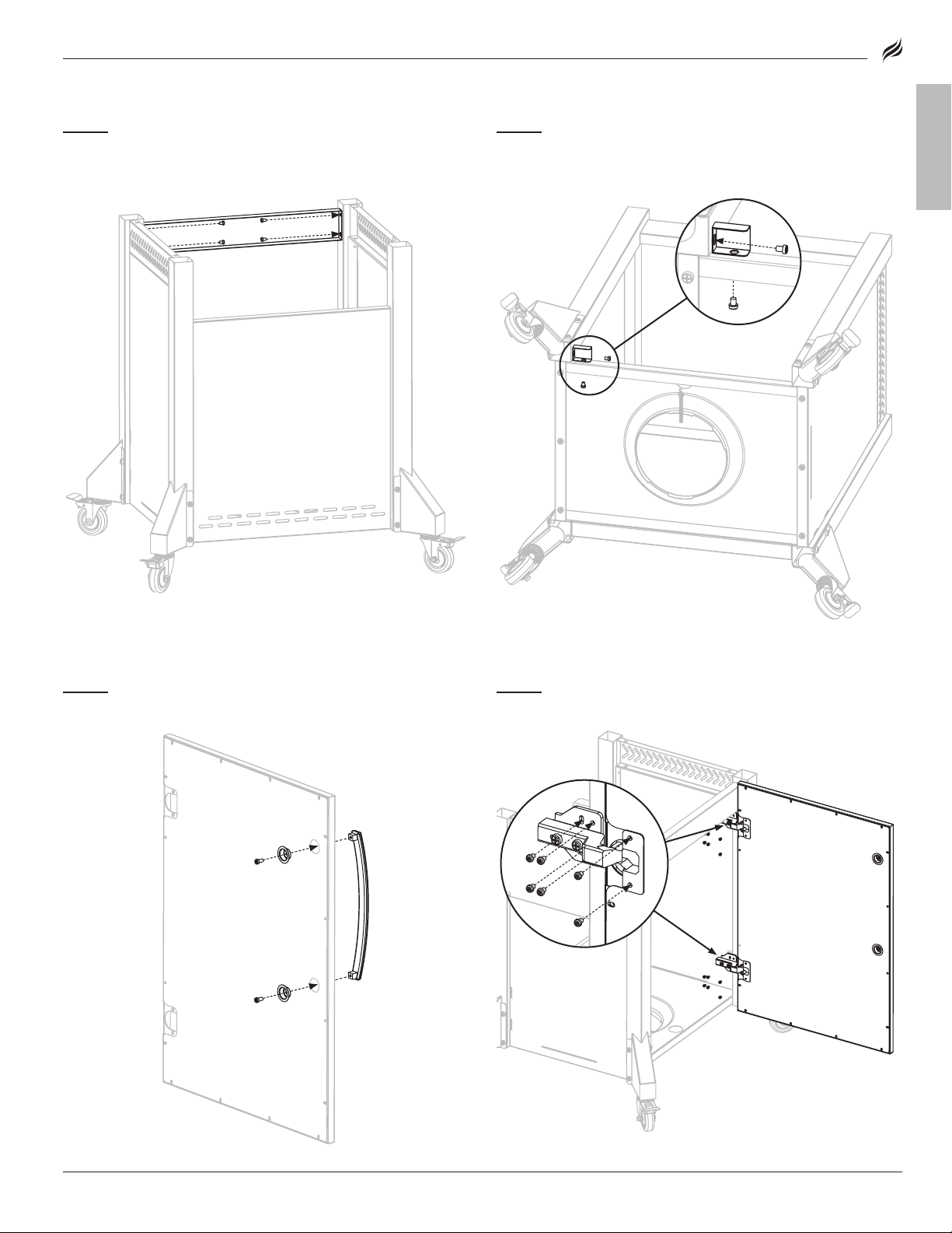
Use four (4) M6x12 screws [b.] to attach the front panel to the
left and right cart panels.
Note: DO NOT fully tighten screws yet.
STEP 14
Use two (2) M6x12 screws [b.] to attach the limiter to the left
cart panel and the cart base.
Note: Tighten all screws from the previous four steps.
ENGLISH
STEP 15
Use two (2) M6x18 screws [d.] to attach the two (2) handle
sleeves and door handle to the cart door.
STEP 16
Use twelve (12) M4x12 countersunk screws [e.] to attach the
two (2) hinges to the door and cart.
BLACKSTONEPRODUCTS.COM/SUPPORT
Page 10
OWNER’S MANUAL | ASSEMBLY GUIDE MODEL: 6831
A
B
STEP 17
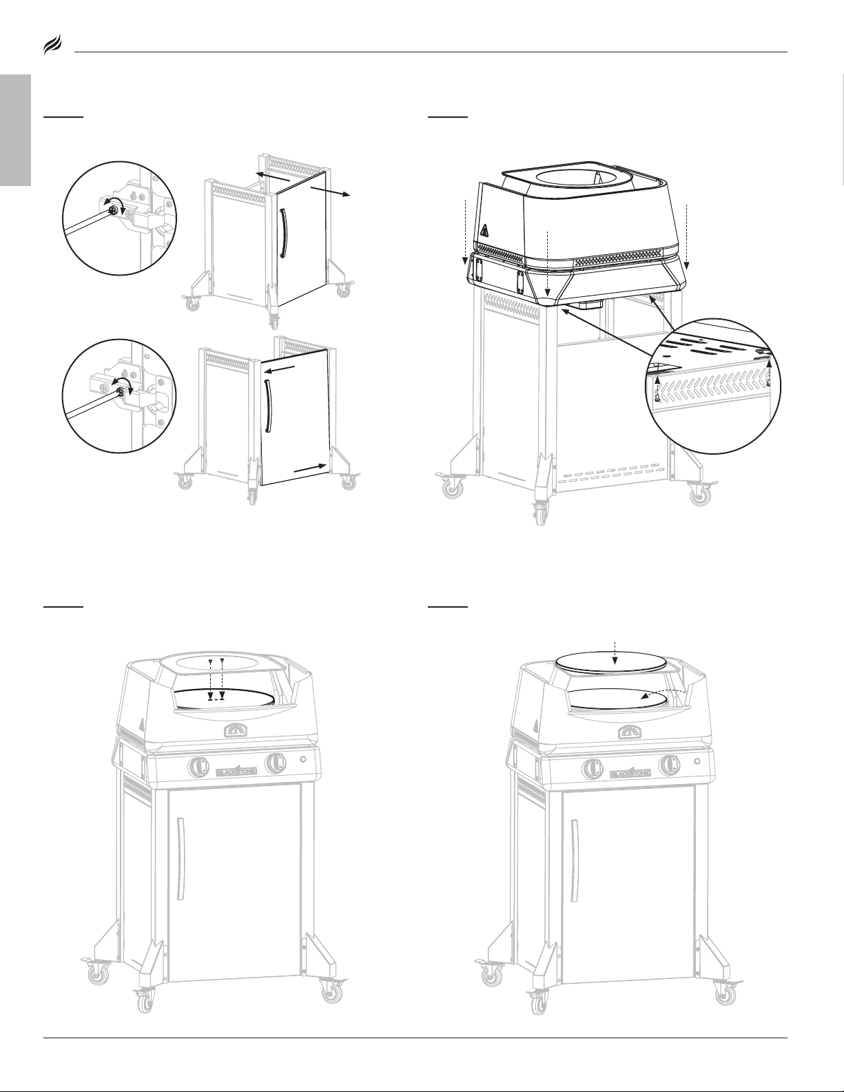
Adjust screws (A) and (B) on the door hinges to align the
door in the cart frame.
ENGLISH
STEP 18
With the help of another person, set the oven body on the
cart. Use four (4) M6x14 black screws [a.] to secure.
A
B
STEP 19
Use two (2) M6x12 countersunk screws [c.] to attach the
turntable to the rotating shaft.
STEP 20
Set one (1) pizza stone on the cast iron turntable. Place one
(1) pizza stone on the upper pizza chamber.
BLACKSTONEPRODUCTS.COM/SUPPORT
Page 11

| OWNER’S MANUALASSEMBLY GUIDEMODEL: 6831
STEP 21
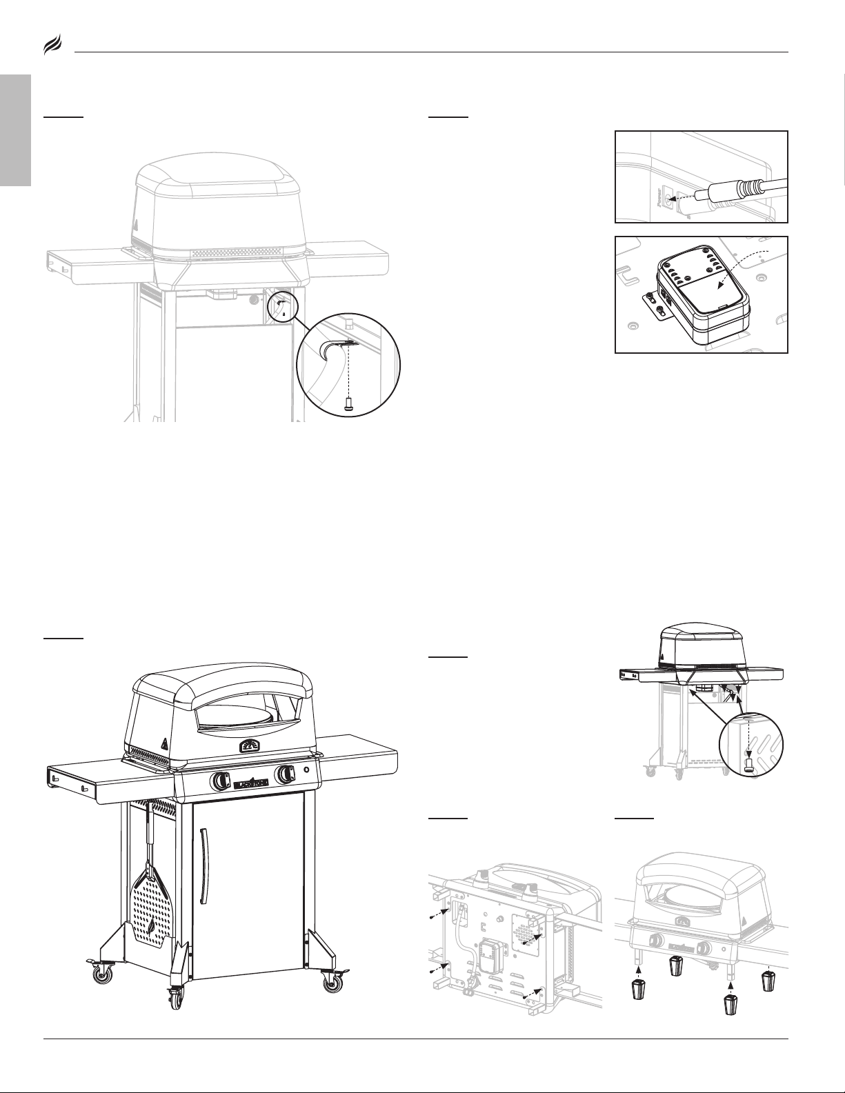
Set the oven lid on the oven body.
STEP 22
Screw two (2) side shelf hooks into one (1) side shelf.
Repeat with the other shelf.
ENGLISH
STEP 23
Use sixteen (16) M6x12 screws [b.] to attach the two (2) side
shelves to the oven body.
STEP 24
If you are right handed, slide the pizza peel holder into the
slots on the right cart panel. If you are left handed, slide the pizza
peel holder into the left cart panel.
The pizza peel can be kept in the pizza peel holder when not in use.
BLACKSTONEPRODUCTS.COM/SUPPORT
Page 12
OWNER’S MANUAL | ASSEMBLY GUIDE MODEL: 6831
STEP 25
Use one (1) M4x12 countersunk screw [e.] to attach the regu-
lator hose fixing sleeve to the left cart panel.
ENGLISH
STEP 26
To power the motor:
OPTION A: Plug the power cord
into the motor.
OPTION B: Insert four (4) AA
batteries into the motor.
(DO NOT use the batteries and
the AC power supply at the
same time.)
STEP 27
Proceed to USING YOUR BLACKSTONE.
FOR TABLETOP USE:
STEP 01
Remove the four (4)
M6x14 black screws that are
securing the oven body to the
cart, and the screw attaching the
regulator to the left panel.
STEP 02
Thread the four M6x14
black screws back into the
oven body.
STEP 03
Slide the four (4) feet
onto the legs.
BLACKSTONEPRODUCTS.COM/SUPPORT
Page 13
A = 36 in (1 m)
A
A
A
A
A
Both ends open
30%
30%
Venturi
Air intake
Blocked burner
Fuel nozzle
Burner opening
MODEL: 6831
| OWNER’S MANUALUSING YOUR BLACKSTONE
USING YOUR BLACKSTONE
BEFORE COOKING
CHECK BURNERS
Prior to connection and use, ensure that there is no debris caught in,
or damage to, the head of the gas cylinder, regulator, hose, burner
and burner ports.
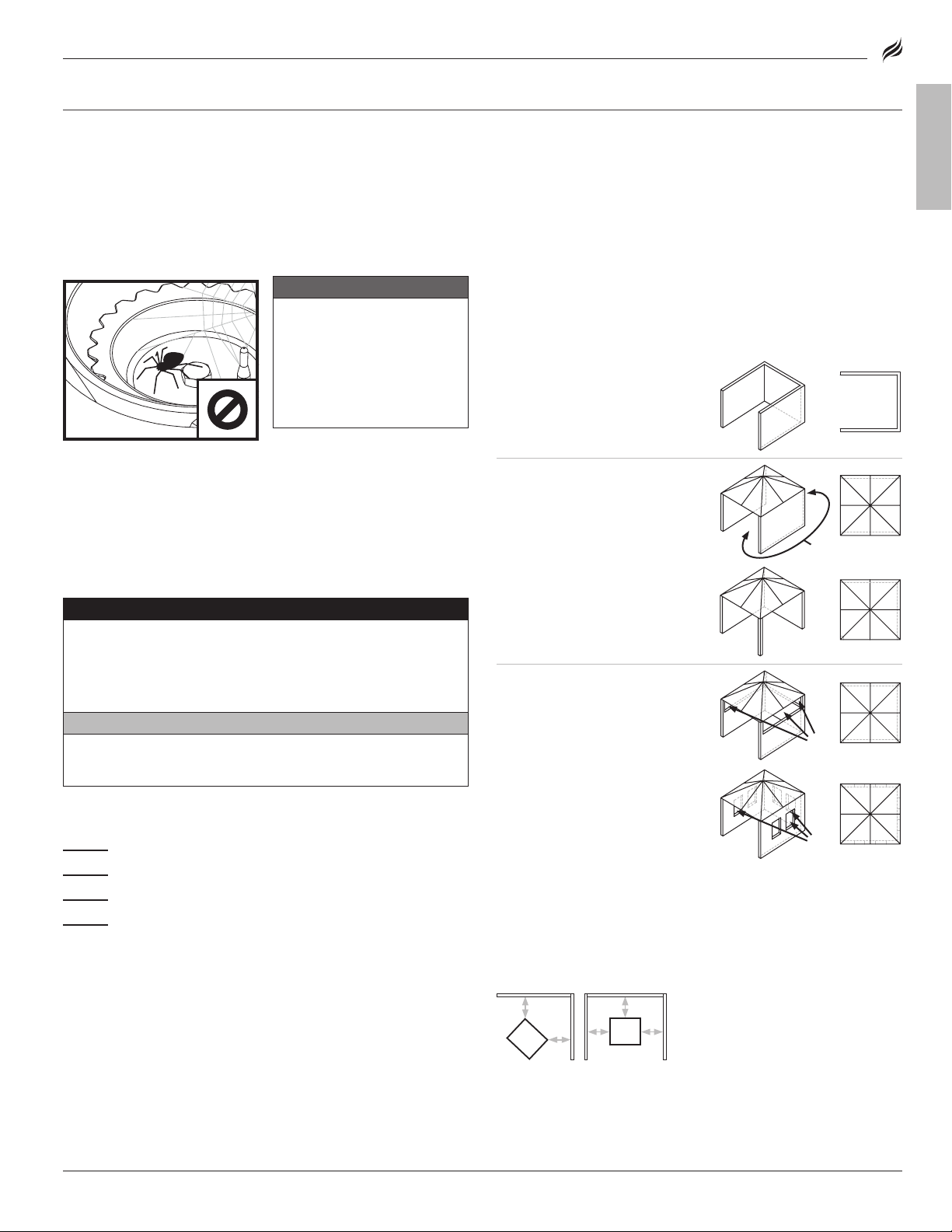
Spiders and insects can nest within and clog the burner/venturi tube
at the orifice.
Blocked burner
Venturi
Air intake
Fuel nozzle
rail fuel nozzle orifice is
correctly engaged within the
burner opening.
Burner opening
THE MINIMUM AMBIENT OPERATING TEMPERATURE IS 0°F (-18°C).
DANGER
Flammable items can combust if placed near the appliance.
Keep the appliance area clear and free from combustible
materials, aerosol containers, gasoline and other flammable
vapors and liquids.
CAUTION
If the appliance is fitted with a paper towel holder, the arm
must be in the open position while the appliance is in use.
WARNING
A clogged burner can
lead to a fire beneath the
appliance.
Burner should be removed
and cleaned whenever
blockages are found.
Ensure that the gas
SETTING UP YOUR OUTDOOR SPACE
THIS APPLIANCE MUST ONLY BE USED OUTDOORS.
• DO NOT use this appliance inside buildings, garages, or any other
enclosed area.
• DO NOT install this appliance in or on a boat.
• DO NOT install this appliance in or on a recreational vehicle.
SHELTERED OUTDOOR AREAS:
All openings must be permanently open; sliding doors, garage doors,
windows or screened openings are not considered as permanent
openings.
An appliance is considered to be outdoors if installed with shelter no
more inclusive than:
a. With walls on three sides, but
with no overhead cover.
b. Within a partial enclosure that
includes an overhead cover
and no more than two sidewalls. The sidewalls may be
parallel, as in a breezeway, or
at right angles to each other.
c. Within a partial enclosure that
includes an overhead cover
and three sidewalls, as long as
30% or more of the horizontal
periphery of the enclosure is
permanently open.
Both ends open
30%
ENGLISH
IF GREASE OR OTHER HOT MATERIAL DRIPS ONTO VALVE, HOSE OR
REGULATOR:
STEP 01
STEP 02
STEP 03
STEP 04
Instructions)
BLACKSTONEPRODUCTS.COM/SUPPORT
Turn o gas supply immediately.
Determine the cause and correct it.
Clean and inspect valve, hose and regulator.
Perform a leak test. (Please reference the Leak Test
MAINTAIN PROPER CLEARANCES FROM COMBUSTIBLE MATERIAL.
• DO NOT use this appliance on or under any apartment or condominium balcony or deck.
• DO NOT obstruct the flow of combustion and ventilation air.
• DO NOT operate this appliance any closer than 36 in (1 m) from the
sides and back of the appliance to combustible construction.
A
A = 36 in (1 m)
• DO NOT use this appliance under overhead combustible
construction.
A
A
A
A
30%
Page 14
OWNER’S MANUAL | USING YOUR BLACKSTONE
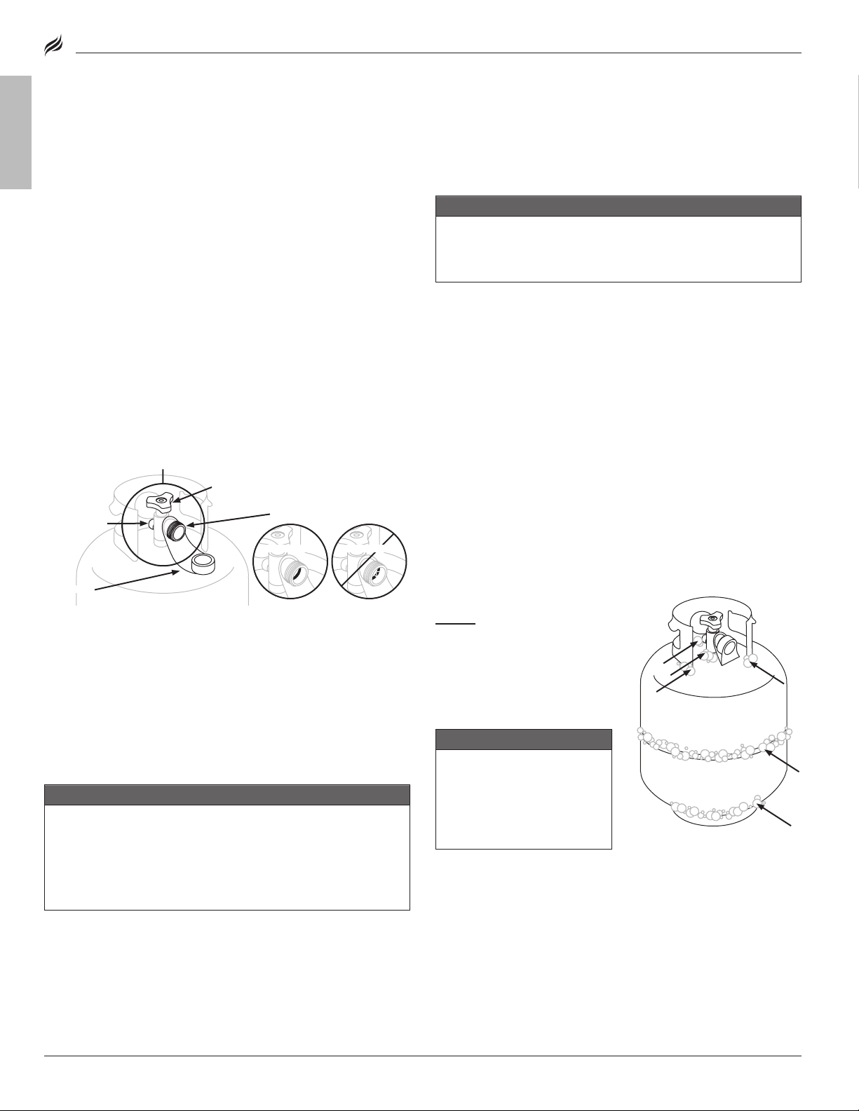
(Indicated by arrows in figure 01.)
Your retailer can help you match a replacement LPG cylinder to your appliance.
• • Always keep new LPG cylinders in upright position during use, transit or
storage.
• • Always keep the ventilation opening(s) of the cylinder enclosure free and
clear from debris.
(Use only Blackstone approved valve, hose, or regulator. Failure to comply will
void the warranty.)
LPG cylinder valveLPG cylinder valve
Safety relief
valve
OPD hand wheel
Type 1 valve outlet
(check seal before use)
GOOD SEALGOOD SEAL
BAD SEALBAD SEAL
Dust cap
figure 01
MODEL: 6831
LPG CYLINDER REQUIREMENTS
FOR 20 LB (9 KG CYLINDERS)
ENGLISH
• The LPG supply cylinder to be used must be constructed and
marked in accordance with the specifications for LP gas cylinders, U.S. Department of Transportation (DOT) or the Standard for
Cylinders, Spheres and Tubes for the Transportation of Dangerous
Goods, CAN/CSA-B339.
• Only LPG cylinders marked “propane” shall be used.
• The LPG cylinder supply system must be arranged for vapor
withdrawal.
Always keep new LPG cylinders in upright position during use, transit or
storage.
Always keep the ventilation opening(s) of the cylinder enclosure free and
clear from debris.
THE LPG CYLINDER VALVE MUST HAVE:
• Type 1 valve outlet (thread on the outside).
• Safety relief valve.
• UL listed Overfill Protection Device (OPD). This OPD safety feature is
identified by a unique triangular hand wheel.
• Dust cap.
OPD hand wheel
Type 1 valve outlet
Safety relief
valve
(check seal before use)
FILLING & ExCHANGE
• Use only those reputable exchange companies that inspect, precision fill, test and certify their cylinders. LPG dealer must purge new
cylinder before filling.
• Volume of propane in cylinder will vary by temperature.
WARNING
A frosty regulator indicates gas overfill.
Immediately close LPG cylinder valve and call local LPG
dealer for assistance.
• DO NOT release liquid petroleum gas (LPG) into the atmosphere.
• To remove gas from LPG cylinder, contact a certified LPG dealer or
local fire department for assistance.
• Exchange cylinder only for an OPD safety feature-equipped
cylinder.
Your retailer can help you match a replacement LPG cylinder to your appliance.
LEAK TEST INSTRUCTIONS
• Leak test new and exchanged LPG cylinders BEFORE connecting
to griddle.
• DO NOT smoke during leak test.
• DO NOT use an open flame to check for gas leaks.
• Appliance must be leak tested outdoors in a well-ventilated
area, away from ignition sources such as gas fired or electrical
appliances.
• During leak test, keep appliance away from open flames or sparks.
Dust cap
The seal on the type 1 valve outlet could, over time, show marked and
visible damage or deterioration that might cause a leak even with
the connection tightened.
• A visual inspection for the seal must be carried out every time a
LPG cylinder is replace or refilled.
• Any LPG cylinder showing signs of damage or deterioration as
those illustrated including visible cracks and pitting, must be
returned unused to the seller.
STORING LPG CYLINDERS
WARNING
• DO NOT store a spare LPG cylinder under, near, or in this
appliance.
• DO NOT fill an LPG cylinder beyond 80% full.
If the information above is not followed exactly, a fire causing
death or serious injury may occur.
• The LPG cylinder must be turned OFF when the appliance is
not in use.
• LPG cylinders must be stored outdoors and out of the reach
of children.
• DO NOT store an LPG cylinder inside a building, garage, or any other
enclosed area.
LEAK TEST: LPG CYLINDER
STEP 01
Use a clean paintbrush
figure 01
to brush a mild soap and
water solution onto joint areas of
the LPG cylinder.
(Indicated by arrows in figure 01.)
• Leaks are indicated by
growing bubbles.
WARNING
If growing bubbles appear
during leak test, DO NOT use
or move the LPG cylinder.
Immediately contact an LPG
supplier or fire department.
FITTINGS & HOSES
• Annual checking and tightening of metal fittings is recommended.
• Keep the fuel supply hose away from any heated surfaces.
• Before each use, check to see if hoses are cut or worn.
• Replace damaged hose before using appliance.
(Use only Blackstone approved valve, hose, or regulator. Failure to comply will
void the warranty.)
BLACKSTONEPRODUCTS.COM/SUPPORT
Page 15
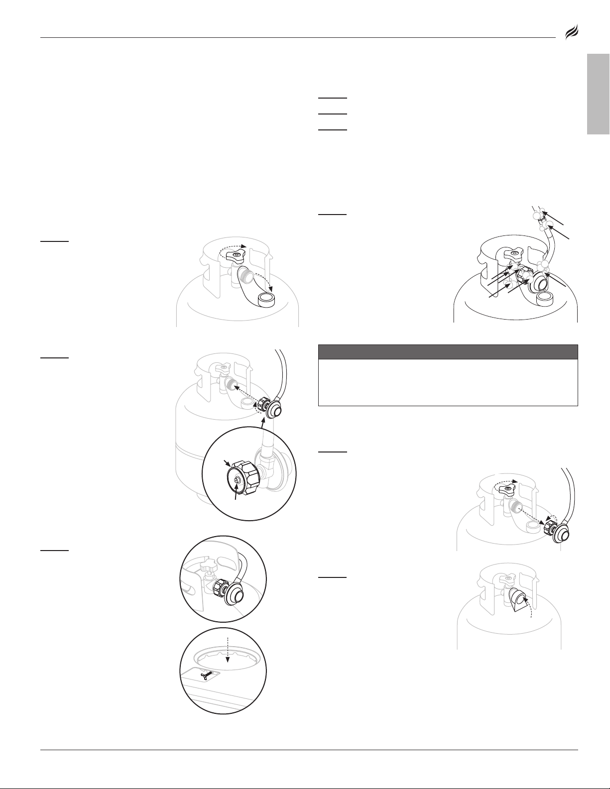
❶
❷
If connection cannot be completed,
disconnect regulator and repeat this
step.
(Indicated by arrows in figure 02.)
❶
❷
Only install the type of dust cap on
cylinder valve outlet that is provided
with the cylinder valve. Other types of
caps or plugs may result in leakage of
propane.
Regulator must be replaced with a Blackstone approved model by a professionally licensed, authorized dealer.
❶❶
❷
Coupling nutCoupling nut
Regulator nippleRegulator nipple
figure 02
❶❶
❷
MODEL: 6831
| OWNER’S MANUALUSING YOUR BLACKSTONE
REGULATOR SAFETY
• Use this appliance, as purchased, only with gas and regulator/
valve assembly supplied. DO NOT use quick connect fittings or
other add-ons.
• DO NOT cross thread (force at an improper angle) the connection
between your LPG cylinder and regulator.
• If you can not connect the regulator, DO NOT use the regulator.
Regulator must be replaced with a Blackstone approved model by a professionally licensed, authorized dealer.
CONNECT THE LPG CYLINDER
ONLY USE A 20 LB (9 KG) CYLINDER
STEP 01
knobs to OFF.
❶
is OFF by turning the OPD hand
wheel clockwise to a full stop.
❷
the Type 1 valve outlet.
STEP 02
straight line with the Type 1 valve
outlet so as not to cross thread
the connection.
Center and insert the regulator nipple into the Type 1
valve outlet.
Hand-tighten the coupling nut in
a clockwise direction.
(DO NOT use tools to connect.)
If connection cannot be completed,
disconnect regulator and repeat this
step.
STEP 03
the cart base. Tighten the cart
base wing screw to secure it to
the appliance.
The safety relief valve must face
away from the user while the
appliance is in use.
Turn the control
Ensure that the LPG cylinder
Remove the safety cap from
Hold the regulator in a
Set the LPG cylinder on
LEAK TEST: VALVES, HOSE & REGULATOR
STEP 01
STEP 02
STEP 03
Turn the control knobs to OFF.
Connect the regulator to the LPG cylinder.
Completely open the LPG tank by turning the OPD hand
wheel counterclockwise.
• If you hear a rushing sound, turn gas o immediately. There is a
major leak at the connection.
• Immediately close the LPG cylinder by turning the OPD hand wheel
clockwise and re-tighten connections. If leaks cannot be stopped
DO NOT TRY TO REPAIR.
STEP 04
Use a clean paintbrush
to brush a mild soap and
water solutionn onto joint areas
of valves and regulator.
(Indicated by arrows in figure 02.)
• Leaks are indicated by
❷
growing bubbles.
• Immediately close the LPG
cylinder by turning the OPD
hand wheel clockwise and
re-tighten connections.
If leaks cannot be stopped, DO NOT try to repair.
Regulator must be replaced with a Blackstone approved
model by a professionally licensed, authorized dealer.
DISCONNECTING THE LPG CYLINDER
STEP 01
❶
is OFF by turning the OPD hand
wheel clockwise to a full stop.
❷
er-clockwise by hand to remove
the regulator. (DO NOT use tools
to disconnect.)
STEP 02
cylinder valve outlet whenever
cylinder is not in use.
Only install the type of dust cap on
cylinder valve outlet that is provided
with the cylinder valve. Other types of
caps or plugs may result in leakage of
propane.
Ensure that the control knobs are turned to OFF.
Ensure that the LPG cylinder
Turn the coupling nut count-
Place dust cap on LPG
ENGLISH
figure 02
WARNING
❷
BLACKSTONEPRODUCTS.COM/SUPPORT
Page 16
OWNER’S MANUAL | USING YOUR BLACKSTONE
❸
❷
❶
❹
❶
❷
❸
❹.
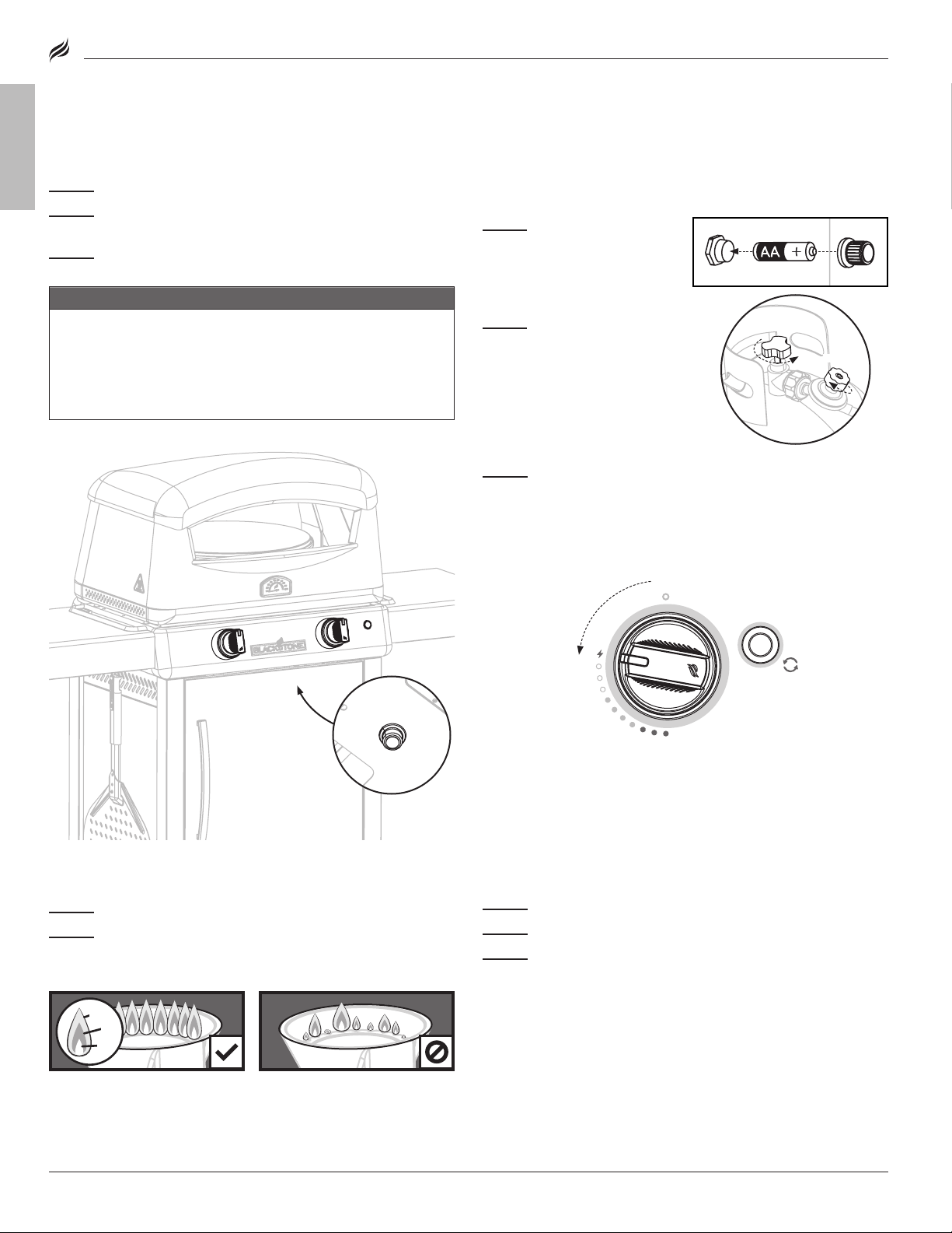
For precision control of your temperature, use the control knob and the red
knob on the adjustable regulator to control the temperature of your Pizza Oven.
tightentighten
1 to 3 turns1 to 3 turns
• • Turn both knobs to HIGH to preheat.
• • While cooking, the left knob should always be on LOW.
• • At the end of cooking, adjust the left knob towards HIGH to finish browning
the crust, if desired.
STEP 02
Turn gas ON by turning
the gas cylinder handwheel
counterclockwise 1 to 3 turns.
2. BATTERY POWERED IGNITION
Before starting ensure all knobs are turned to OFF.
❶❶
STEP 01
Insert one (1) AA
battery (not included) under the
ignitor button.
Screw the button into place over
the positive terminal.
STEP 03
❷❷
Push and hold the ignitor button.
If knobs
DO NOT
spring back, replace valve assembly before using appliance.
1 to 3 turns1 to 3 turns
❶❶
❷❷
❸❸
❶
❷
❸
HEALTHY FLAME PATTERN YELLOW OR IRREGULAR
3. ALWAYS CHECK BURNER FLAME BEFORE USE.
STEP 01
Light burners and rotate knobs from HIGH to LOW.
STEP 02
Look below the cooking surface to view burners. When knob
is at HIGH, flames should be larger than when knob is at LOW.
❶❶
Flickers of yellow color. Flickers of yellow color.
❷❷
Dark blue color. Dark blue color.
❸❸
Vibrant blue. Vibrant blue.
If there is a sudden drop or low If there is a sudden drop or low
flame issue, please reference the flame issue, please reference the
Troubleshooting chapter. Troubleshooting chapter.
IF IGNITION DOES NOT OCCUR IN 5 SECONDS:
STEP 01
Turn the burner control knob OFF.
STEP 02
Wait 5 minutes.
STEP 03
Repeat the lighting procedure.
If burner does not ignite, please reference the Troubleshooting chapter. If burner does not ignite, please reference the Troubleshooting chapter.
If burner does not ignite, please reference the Troubleshooting chapter.
❶
Flickers of yellow color.
❷
Dark blue color.
❸
Vibrant blue.
If there is a sudden drop or low
flame issue, please reference the
Troubleshooting chapter.
IGNITION INSTRUCTIONS
MODEL: 6831
1. CHECK VALVES
ENGLISH
STEP 01
STEP 02
If knobs
STEP 03
Turn knob to OFF position.
Push in knob and release. Knob should spring back.
DO NOT
spring back, replace valve assembly before using appliance.
Rotate knob to LOW then turn back to OFF. Knob should
turn smoothly.
WARNING
If burner does not ignite with open gas supply valve, gas
will continue to flow out of burner and could accidentally/
inadvertently ignite with risk of injury.
Ensure gas is o at the supply shut o valve before checking
appliance valves.
2. THERMOCOUPLE SURE-START IGNITION
Remove the oven door. DO NOT use the oven door at any time
Note: The right control knob is the main cooking knob. The left
while the oven is in use.
should be used for pre-heating and finishing.
STEP 01
battery (not included) under the
battery cap.
Screw the cap into place over the
positive terminal.
STEP 02
cylinder by slowly turning the
OPD hand wheel counterclockwise 1 to 3 turns.
Tighten the red knob on the
regulator clockwise to its HIGH
position, then loosen 1 and a
half turns.
STEP 03
motor.
quarter turn to LOW. Hold in for 10~20 seconds until thermocouple
heats up. You should hear the igniter clicking the entire time. (When
you release the knob, the oven should remain lit.) Once the flame is
consistent, adjust to desired temperature
Insert one (1) AA
Turn gas ON at the LPG
Turn the Pizza Oven control knob to OFF.
❶
Push in the control knob and turn counterclockwise a
❸
❶
❸
❷
❹.
❷
Turn on the
3. ALWAYS CHECK BURNER FLAME BEFORE USE.
STEP 01
STEP 02
HIGH, flames should be larger than when knob is at LOW.
HEALTHY FLAME PATTERN YELLOW OR IRREGULAR
❶
❷
❸
Light burner and rotate knob from LOW to HIGH.
Look below the turntable to view burner. When knob is at
❶
❷
❸
Flickers of yellow color.
Dark blue color.
Vibrant blue.
If there is a sudden drop or low
flame issue, please reference the
Troubleshooting chapter.
❹
For precision control of your temperature, use the control knob and the red
Turn both knobs to HIGH to preheat.
knob on the adjustable regulator to control the temperature of your Pizza Oven.
While cooking, the left knob should always be on LOW.
At the end of cooking, adjust the left knob towards HIGH to finish browning
the crust, if desired.
IF IGNITION DOES NOT OCCUR IN 5 SECONDS:
STEP 01
STEP 02
STEP 03
If burner does not ignite, please reference the Troubleshooting chapter.
Turn the burner control knob OFF.
Wait 5 minutes.
Repeat the lighting procedure.
BLACKSTONEPRODUCTS.COM/SUPPORT
Page 17
HOW TO USE YOUR PIZZA OVEN
FRESH PIZZA
STEP 01
Preheat your oven on high for about 20-25 minutes.
STEP 02
Once the desired stone temperature is reached (650°-750°F
(340°- 400°C) for fresh dough pizza), turn the control knob to low.
Depending on what you are cooking, you may adjust the temperature
while cooking to achieve desired results.
Note: The thermometer only measures the air temperature in the
oven, NOT the stone temperature. Use an infrared thermometer (not
included) to measure the bottom stone temperature. Proper stone
temperature is critical for consistent results.
STEP 03
Pizza cooking time is about 2-4 minutes depending on the
size and thickness of the pizza.
• Thinner foods should be cooked at a higher temperature for a
If necessary, reference the Troubleshooting chapter for instructions on
cleaning the burner.
MODEL: 6831
| OWNER’S MANUALUSING YOUR BLACKSTONE
COOKING ON YOUR BLACKSTONE
CAUTION
This appliance will be hot during and after use. Use longhandled utensils and oven mitts/ protective gloves when
handling potentially hot parts, including handles close to the
appliance body, to protect against burns and splatters.
VIDEO RECIPES
Find recipes and cooking tips at:
BlackstoneProducts.com/recipes
youtube.com/BlackstoneGriddles
@blackstoneproducts
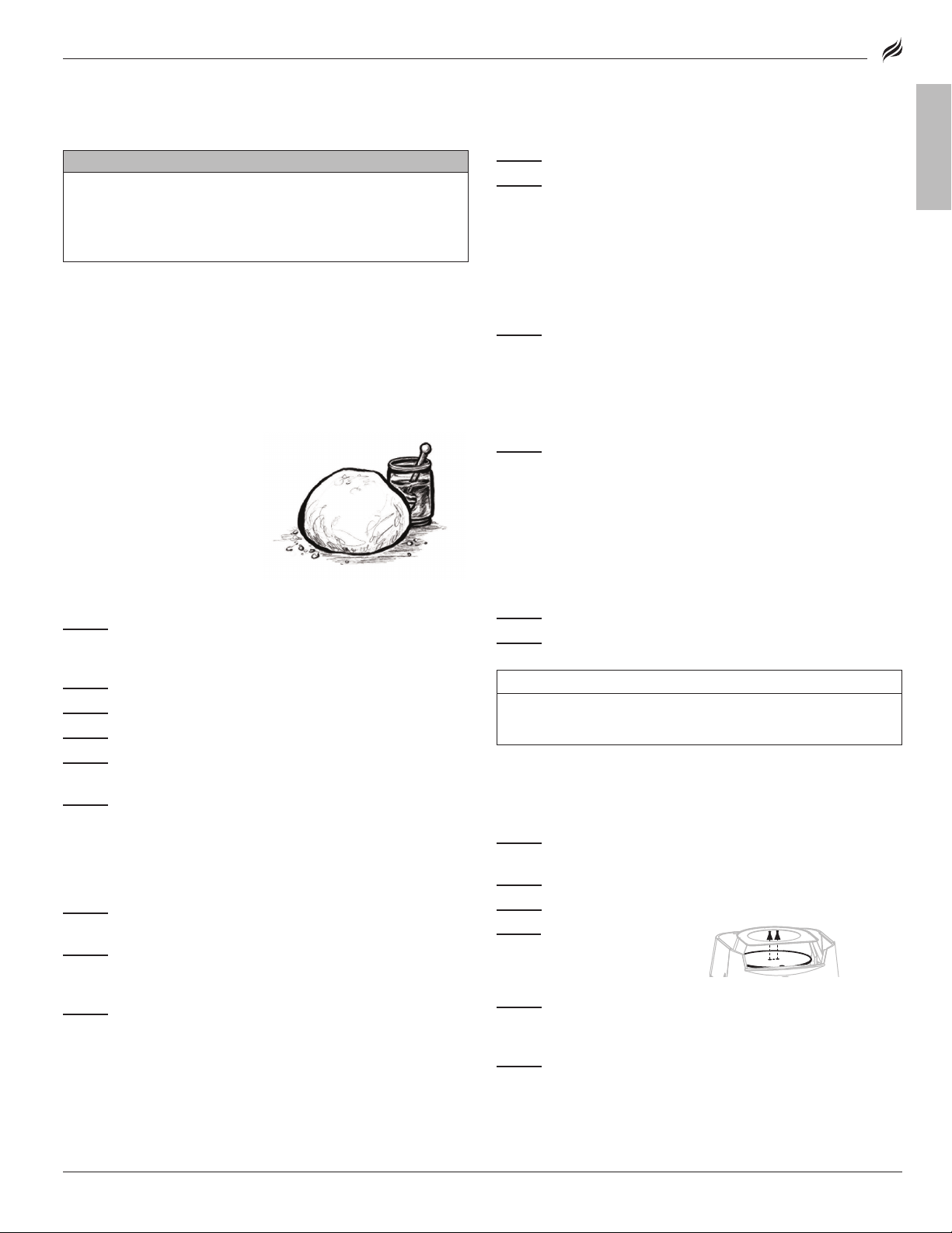
NEW YORK STYLE PIZZA DOUGH
1 hour 30 min.
INGREDIENTS
• 4 cups of bread flour
• 1 and cups of warm water
• 1 teaspoon of instant dry yeast
• 3 teaspoons of honey
• 2 teaspoons of salt
• 4 teaspoons of olive oil
STEP 01
add the oil and salt yet. You want the flour to hydrate first before
adding oil.)
STEP 02
STEP 03
STEP 04
STEP 05
dough balls with oil or cooking spray.
STEP 06
HOW TO STRETCH PIZZA DOUGH
Important: Having your dough at room temp will make stretching it
much easier. Cold dough is very diicult to work with.
STEP 01
from sticking.
STEP 02
from the center out. Using a rolling pin is fine but won’t give you a
puy crust.
STEP 03
Rotate the dough from hand to hand letting gravity do most of the
work stretching it out.
Note: Use a small amount of flour, semolina, or cornmeal on your
pizza peel to prevent sticking.
BLACKSTONEPRODUCTS.COM/SUPPORT
Add water, flour, yeast, honey together in a large bowl. (Don’t
Mix the dough until most of the flour is incorporated.
Add the oil and salt and knead your dough for 5-10 minutes.
Cover dough and let it rest for 10-15 minutes.
Divide the dough into 3 pieces and round into balls. Wipe the
Cover dough balls and let rise for about an hour.
Generously flour your prep surface to prevent dough
Flatten the dough with the palm of your hand, starting
Pick up the dough and put it on the back of your hands.
HOW TO USE YOUR PIZZA OVEN
FRESH PIZZA
STEP 01
STEP 02
Preheat your oven on high for about 12-15 minutes.
Once the desired stone temperature is reached (650°-750°F
(340°- 400°C) for fresh dough pizza), turn the control knob to low.
Depending on what you are cooking, you may adjust the temperature
while cooking to achieve desired results.
Note: The thermometer only measures the air temperature in the
oven, NOT the stone temperature. Use an infrared thermometer (not
included) to measure the bottom stone temperature. Proper stone
temperature is critical for consistent results.
STEP 03
Pizza cooking time is about 2-4 minutes depending on the
size and thickness of the pizza.
• Thinner foods should be cooked at a higher temperature for a
shorter time.
• Thicker or denser foods should be cooked at a lower temperature
for a longer time.
STEP 04
Pull the pizza out when the crust has reached your desired
readiness, or when the edges of the pizza crust are golden-brown.
FROZEN PIZZAS, COOKIES, ETC.
Follow the food manufacturer’s directions. Let frozen food thaw a
little before putting it into the hot oven. This will prevent your pizza
stone from cracking.
CLEANING YOUR PIZZA STONE
STEP 01
STEP 02
and use the cleaner side.
Set your oven to HIGH for 15~20 min to burn o residue.
Once your oven has cooled completely, flip the stone over
NOTICE
DO NOT use soap on the cooking stone. This will leave a soap
taste in food.
CLEANING YOUR OVEN INTERIOR
If the pizza falls o the rotating stone and catches on fire:
STEP 01
OFF the rotating motor.
STEP 02
STEP 03
STEP 04
by removing the two (2) bolts
that attach the turntable to the
rotating shaft.
STEP 05
cavity floor. Wipe cooking cavity with a damp cloth. DO NOT use
detergent.
STEP 06
cooking chamber.
If necessary, reference the Troubleshooting chapter for instructions on
cleaning the burner.
Turn OFF the control knob, turn OFF the LPG cylinder, turn
Allow the oven to completely cool.
Remove the oven lid, the top stone, and the lower stone.
Remove the turntable
Use a spatula to scrape and remove debris from cooking
Use a vacuum if necessary to clean out food debris inside
ENGLISH
Page 18
OWNER’S MANUAL | USING YOUR BLACKSTONE
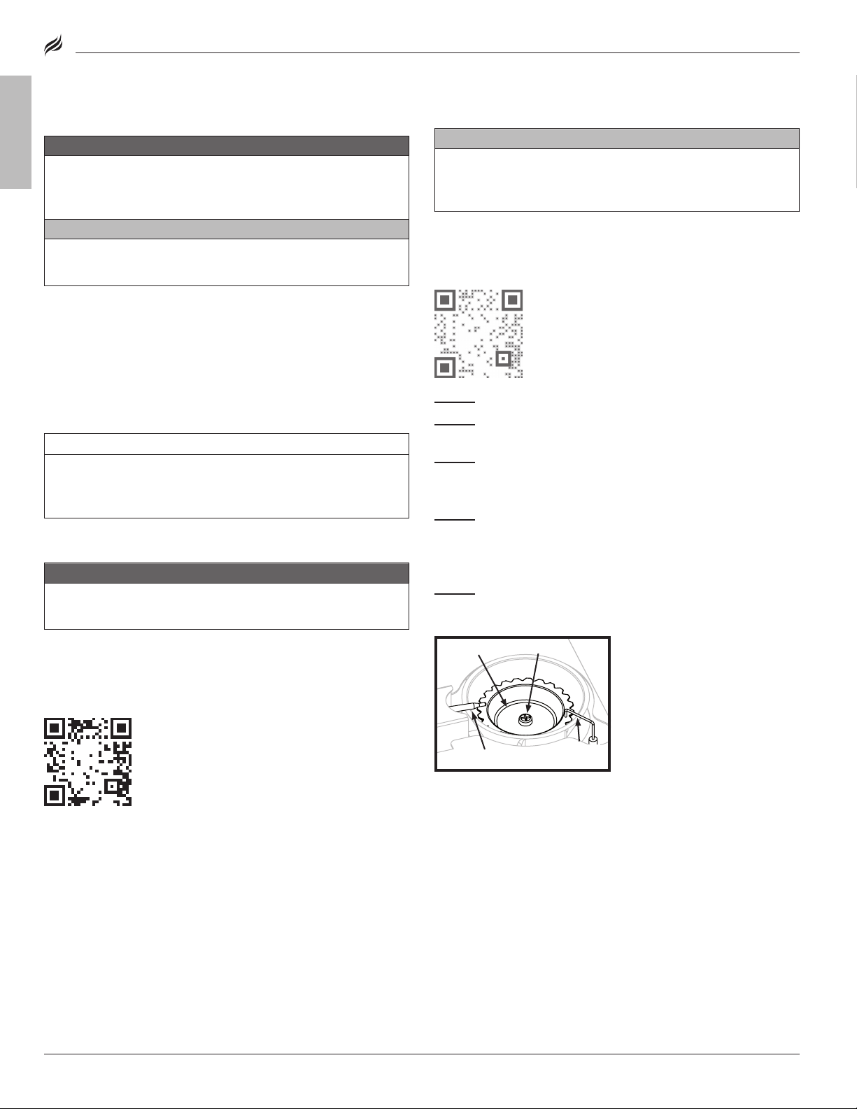
STEP 02
❶❶
Remove the base panel cover
from the base of the unit.
❷❷
Disconnect the orifice
nozzle and gas line from the
burner tube.
STEP 03
Use compressed air to
clear the burner tubes.
Note: Once reinstalled, the
gas line should be leak tested
to ensure there are no holes
in the line.
CLEANING THE BURNER ASSEMBLY
CAUTION
All cleaning and maintenance should be carried out when the
appliance is cool and with the fuel supply turned OFF at the
gas cylinder.
STEP 01
Run a nylon brush over
the outer surface of the burner to
remove grime.
❶❶
❷❷
Bolt
Burner cap
Ignitor
needle
Thermocouple
MODEL: 6831
CARE AND MAINTENANCE
ENGLISH
Grease build up can cause a fire. Clean any part of the
appliance that gets hot and experiences grease build up after
each use.
All cleaning and maintenance should be carried out when the
appliance is cool and everything is turned OFF.
• DO NOT use abrasive pad on areas with graphics.
• If a bristle brush is used to clean any of the cooking surfaces,
ensure no loose bristles remain on cooking surfaces prior
to cooking.
APPLIANCE BODY:
Wash with warm soapy water and immediately wipe dry with a
non-abrasive cloth. (DO NOT allow cleaning agents to rest on any
porous surface for a prolonged amount of time.)
DO NOT use Citrisol, abrasive cleaners, or a concentrated
cleaner on the appliance. This may result in damage to and
failure of parts.
APPLIANCE STORAGE
DO NOT move the appliance when in use. Allow the appliance
to cool to 115°F (45°C) before moving or storing.
WARNING
CAUTION
NOTICE
WARNING
CLEANING THE BURNER ASSEMBLY
CAUTION
All cleaning and maintenance should be carried out when
the appliance is cool and with the fuel supply turned OFF at
the gas cylinder.
To reduce chance of “flash-back” the procedure below should be
followed at least once a month when spiders are most active or
when your appliance has not been used for a period of time.
STEP 01
STEP 02
eye protection)
STEP 03
Remove the turntable.
Use compressed air to blow out the burner scallops. (Wear
Remove the bolt and burner cap.
Note: DO NOT disturb the ignitor needle or thermocouple
while cleaning.
STEP 04
Clean the inside of the burner:
• Run a narrow bottle brush through the burner several times. (DO
NOT use wire brushes)
• Use compressed air to blow out the burner. (Wear eye protection)
STEP 05
Replace burner cap and bolt.
If problems persist, contact customer support.
VIDEO TUTORIAL
Pizza Oven Troubleshooting
Storage of an appliance indoors is only permissible if the gas supply
is disconnected and removed from the appliance.
COVER FIT GUIDE
Always cover your appliance when stored outdoors.
To find a cover that will fit your appliance, visit
BlackstoneProducts.com/support.
Burner cap
Thermocouple
Bolt
Ignitor
needle
BLACKSTONEPRODUCTS.COM/SUPPORT
Page 19
Obstructions in the burner, gas
Clean the burner, jets, and gas
Gas cylinder is empty or low.
Refill or replace the gas
The regulator’s flow limiting
Reset the safety system:
STEP 01
close the gas cylinder valve, and
disconnect the regulator from
the gas cylinder.
STEP 02
allow the pressure to dissipate,
then reconnect the regulator to
the gas cylinder and slowly open
the gas cylinder hand wheel one
to three turns.
STEP 03
If this does not work, to determine the cause, please try to ignite your appliance with a match.
Before beginning, check for gas leaks. Open hood (if applicable).
Ignitor wire misaligned.
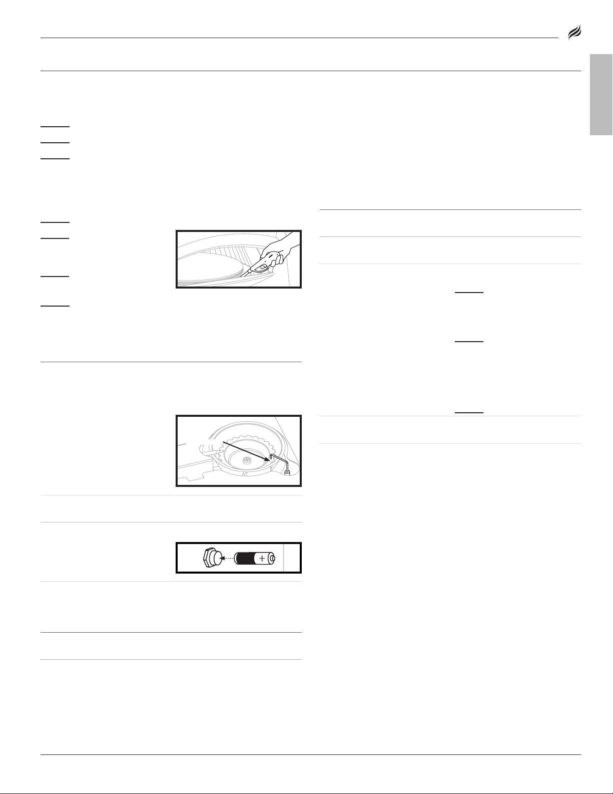
Ensure that the ignitor needle
inch) away from the burner, and
Damage to the ignition system.
Contact customer support for
Burner tubes are not receiving
Clean the burner assembly to
burner
air gate
gas rail & valves
3-7mm
(- inch)
Dead / improperly installed
Replace with new battery.
3-7mm
(- inch)
MODEL: 6831
| OWNER’S MANUALTROUBLESHOOTING
TROUBLESHOOTING
IGNITION TROUBLESHOOTING
BURNER WILL NOT IGNITE:
If ignition does not occur in 5 seconds:
STEP 01
STEP 02
STEP 03
If this does not work, to determine the cause, please try to ignite your appliance with a match.
MATCH LIGHTING INSTRUCTIONS
Before beginning, check for gas leaks. Open hood (if applicable).
STEP 01
STEP 02
lighter) no shorter than 11
inches long.
STEP 03
the burner.
STEP 04
Ensure burner lights and stays lit.
IF YOU CAN IGNITE YOUR APPLIANCE WITH A MATCH:
Turn the burner control knob OFF.
Wait 5 minutes.
Repeat the lighting procedure.
Turn control knob to OFF position.
Light a match (or long
Place the flame next to
Push in and turn the control knob to start gas flowing.
GAS FLOW TROUBLESHOOTING
APPLIANCE WILL NOT ACHIEVE A HIGH HEAT OR HEATS UNEVENLY:
• Burner flames are yellow or irregular.
• Burner flames start strong, then immediately drop to low even
when burner is set to high position.
• Flame height drops when a second burner is lit.
• Flames DO NOT extend the full length of the burner, or only run on
one side of the burner.
• Burner flames are inconsistent.
POSSIBLE CAUSES SOLUTION
jets, or fuel rail.
device was triggered.
hose.
cylinder.
Turn OFF the appliance,
Wait five minutes to
ENGLISH
POSSIBLE CAUSES SOLUTION
is positioned 3-7mm (1/8-1/4
aligned with the burner holes.
3-7mm
(- inch)
3-7mm
(- inch)
replacement parts.
battery.
IF YOU CAN NOT IGNITE YOUR APPLIANCE WITH A MATCH:
POSSIBLE CAUSES SOLUTION
Regulator stuck in safety
position.
Contact customer support for
replacement parts.
• A flame is coming out of
the air gate:
POSSIBLE CAUSES SOLUTION
Something is blocking the
venturi in the burner.
Clean the burner assembly to
remove the obstruction.
Ignite your appliance.
burner
air gate
gas rail & valves
fuel.
BLACKSTONEPRODUCTS.COM/SUPPORT
remove the obstruction.
Page 20

ENGLISH
This product may be covered by one or more issued U.S. and/or
international patents and may include patent applications pending.
For more information, please visit: BlackstoneProducts.com/patents
DISTRIBUTED BY NORTH ATLANTIC IMPORTS, LLC W N LOGAN, UT USA | BLACKSTONE IS A REGISTERED TRADEMARK OF NORTH ATLANTIC IMPORTS, LLC
© NORTH ATLANTIC IMPORTS. ALL RIGHTS RESERVED.
BLACKSTONEPRODUCTS.COM/SUPPORT
 Loading...