

Page 1

BlackRidge Technology Inc.
Part No. 2120-0030-01
Revision 1.0, September 2016
BlackRidge BR-2120
Gateway for AWS
Setup Guide
10615 Professional Circle Suite 201
Reno, NV 89521
U.S.A
Page 2

Preface .................................................................................................................................. 7
About This Guide ......................................................................................................................... 7
Related Material ................................................................................................................... 8
Who Should Use This Guide ........................................................................................................ 9
How This Guide is Organized .................................................................................................... 10
Typographical Conventions ....................................................................................................... 11
SECTION I ............................................................................................................................ 12
Task Map for the BlackRidge BR-2120 TAC Gateway for AWS ............................................... 13
SECTION II ........................................................................................................................... 14
Identify Security Use Case & BlackRidge Solution Requirements ........................................... 15
Security Problem ....................................................................................................................... 15
Setup Requirements ................................................................................................................. 15
VPC Requirements for the BR-2120 Gateway for AMS ......................................................... 16
Select Resources to Trust and to Protect .............................................................................. 17
Criteria to Determine Role(s) ............................................................................................... 18
Trusted Hosts: ................................................................................................................... 18
Protected Resources: ......................................................................................................... 18
Design the Network Topology .............................................................................................. 19
Port Assignments for the BR-2120 Gateway for AWS............................................................ 20
SECTION III .......................................................................................................................... 21
Create and Configure Virtual Private Cloud .......................................................................... 22
Task: Create VPC ....................................................................................................................... 23
Task: Configure Internet Gateway ............................................................................................ 24
Task: Create Subnets ................................................................................................................. 25
Task: Create Route Tables ......................................................................................................... 27
Task: Create Route Under the MGMT Route Table................................................................... 30
1
Page 3

Task: Create Security Groups .................................................................................................... 31
SECTION IV .......................................................................................................................... 35
Launch and Configure a Gateway AMI Instance ................................................................... 36
Task: Configure and Launch an AMI Instance ........................................................................... 36
Task: Stop the AMI Instance ..................................................................................................... 42
Task: Review Settings of the eth0/Management Interface for the AMI Instance .................... 42
Task: Create Additional Interfaces for the AMI Instance .......................................................... 43
Task: Attach Additional Interfaces to the AMI Instance ........................................................... 45
Task: Allocate a New Elastic IP Address for the MGMT Interface ............................................ 46
Task: Associate Elastic IP with MGMT Interface ....................................................................... 47
Task: Modify Route Table for (Trusted + Protected) Side of BRT GW ....................................... 49
Task: Disable Source/Destination Check for Untrusted and Trusted Interfaces ....................... 51
Task: Disable Source/Destination Check for Untrusted and Trusted Interfaces ....................... 53
Task: Associate Elastic IP with the Public/Untrusted Interface ................................................ 54
SECTION V ........................................................................................................................... 55
Deploy a Jump Host into the MGMT Subnet in VPC .............................................................. 56
Task: Create the Jump Host Instance ........................................................................................ 57
Task: Assign an Elastic IP to the Jump Host .............................................................................. 64
SECTION VI .......................................................................................................................... 68
Deploy a (Trusted + Protected) Host into Trusted Subnet in VPC ........................................... 69
Task: Provision an Instance of the Amazon Linux AMI ............................................................. 70
Task: Check Boot Status through AWS CLI ................................................................................ 76
Task: SSH into Trusted + Protected Instance ............................................................................. 77
Task: Configure Static Networking and Routes on the Trusted + Protected Instance .............. 78
SECTION VII ......................................................................................................................... 80
Configure Layer 3 NAT – External-to-VPC (Unidirectional) .................................................... 81
2
Page 4

Task: Inserter – Generate and Export SKEY ................................................................................... 86
Task: Resolver – Import SKEY ........................................................................................................ 86
Task: Inserter – Add NAT and Routes ............................................................................................ 86
Task: Inserter – Add NAT and Routes ............................................................................................ 87
Task: Inserter – Add and Enable Identity ...................................................................................... 88
Task: Inserter – Create Trusted Host and Associate Identity ........................................................ 88
Task: Resolver – Add and Enable Identity Using SKEY .................................................................. 89
Task: Resolver – Add Protected Resource ..................................................................................... 89
Task: Resolver – Add Rule and Link Identity.................................................................................. 90
Task: Inserter – Enable Enforce Mode .......................................................................................... 90
Task: Resolver – Enable Enforce Mode ......................................................................................... 90
SECTION VIII ........................................................................................................................ 91
Configure Layer 3 NAT – VPC-to-VPC (Bidirectional) ............................................................. 92
Task: Inserter + Resolver – Add NAT and Routes .......................................................................... 94
Task: Inserter + Resolver – Configure Trusted Host and Protected Resource ............................... 95
Task: Inserter – Generate and Export SKEY ................................................................................... 95
Task: Resolver – Import SKEY ........................................................................................................ 96
Task: Inserter – Add and Enable Identity ...................................................................................... 96
Task: Inserter – Associate Identity with Trusted Host ................................................................... 97
Task: Resolver – Add and Enable Identity Using SKEY .................................................................. 97
Task: Resolver – Add Rule for and Link Identity to Protected Resource ....................................... 97
Task: Inserter – Enable Enforce Mode .......................................................................................... 98
Task: Resolver – Enable Enforce Mode ......................................................................................... 98
SECTION IX .......................................................................................................................... 99
Add Certificates to BlackRidge TAC Gateway...................................................................... 100
Initiate a BlackRidge Certificate Signing Request (CSR) ....................................................... 101
3
Page 5

Task: Generate BlackRidge TAC Gateway Keys ...................................................................... 102
Task: Generate a Certificate Signing Request (CSR) ............................................................... 102
Loading the BlackRidge Technology-Signed Certificates ........................................................ 103
Task: Extract the Encrypted Certificate File ............................................................................ 103
Importing Certificates into TAC Gateway ............................................................................... 107
Task: Import the Root and Intermediate Certificates ............................................................. 107
Task: Import the BlackRidge TAC Gateway Certificates ......................................................... 108
Task: Validate the BlackRidge TAC Gateway Certificates ....................................................... 108
SECTION X ......................................................................................................................... 109
Testing the Configuration .................................................................................................. 110
Task: Test the Gateways’ Ability to Route Locally in Layer 3 Mode ........................................... 110
Task: Test the Trusted + Protected Connection Using SSH ......................................................... 110
SECTION XI ........................................................................................................................ 111
Set Transport Access Control (TAC) Mode of Operation ...................................................... 112
Task: Display TAC Mode .......................................................................................................... 113
Task: Set TAC Mode as “Bridge” ............................................................................................. 113
Task: Set the TAC Mode as “Monitor” .................................................................................... 114
Task: Set the TAC Mode as “Enforce” ..................................................................................... 114
Congratulations ................................................................................................................. 115
Appendix A: Accessing the BlackRidge Gateway (SSH) ........................................................ 116
Using PuTTY and SSH to Access the Gateways ....................................................................... 116
Appendix B: CLI Commands for Configuring the IP Network Attributes of the BlackRidge TAC
Gateway ........................................................................................................................... 119
Configure DHCP Network Settings for the Management Port ............................................... 119
cfg (static IP) - Configure IPv4 Network Settings for the Management Port ......................... 120
/etc/mgt/ipv6/ – Configure an IPv6 Address on the admin Port ......................................... 121
4
Page 6

add – Associate IPv6 Addresses with the Management Port ................................................. 121
del – Remove IPv6 Addresses from the Management Port ................................................... 121
disable – Disable IPv6 on the Admin Port ............................................................................... 122
enable – Enable IPv6 on the Admin Port ................................................................................ 122
mod – Modify IPv6 Address on the Admin Port ..................................................................... 123
Appendix C: CLI Commands for Configuring the DNS Network Attributes of the BlackRidge TAC
Gateway ........................................................................................................................... 124
/etc/dns/ - DNS Configuration ........................................................................................... 124
cfg - Configure DNS ................................................................................................................. 124
show - Show DNS Settings ...................................................................................................... 125
Appendix D: CLI Commands for Configuring the Host Name Attributes of the BlackRidge TAC
Gateway ........................................................................................................................... 126
/etc/hostname/ - Host Name and Domain Name Configuration ......................................... 126
cfg - Configure Hostname ....................................................................................................... 126
show - Show the Hostname and Domain Name ..................................................................... 127
5
Page 7

Copyright © 2016 BlackRidge Technology, Inc. All rights reserved.
This document is protected by copyright and distributed under licenses restricting its use,
copying, distribution and decompilation. No part of this document may be reproduced in any
form by any means without prior written authorization of BlackRidge Technology Inc.
Documentation is provided as is without warranty of any kind, either expressed or implied,
including any kind of implied or expressed warranty of non-infringement or the implied
warranties of merchantability or fitness for a particular purpose.
BlackRidge Technology Inc. reserves the right to change any products described herein at any
time and without notice. BlackRidge Technology Inc. assumes no responsibility or liability
arising from the use of products described herein, except as expressly agreed to in writing by
BlackRidge Technology Inc. The use and purchase of this product does not convey a license
under any patent rights, trademark rights or any other intellectual property rights of BlackRidge
Technology Inc.
Document Part Number: 2120-0030-01
6
Page 8

Preface
About This Guide
The BlackRidge BR-2120 is a TAC Gateway for Amazon™ Web Services (AWS). There are a
number of initial tasks that must be completed to set up the TAC Gateway(s) for network access
and operation. This document contains the instructions for deploying a single BlackRidge TAC
Gateway into the AWS Elastic Compute Cloud (EC2) cloud server.
The setup instructions are divided into a number of categories, each of which contains one or
more basic tasks to complete. These tasks are designed to simplify the overall process of setting
up your gateway(s) to be operational and connected to the network.
This Setup Guide provides guidance in the following procedures:
Identifying resource requirements
Selecting resources to trust and protect
Designing a network topology
Creation of a Virtual Private Cloud (VPC)
Deployment of a Gateway from AMI
Deployment of a Management Instance in AWS
Deployment of trusted hosts/protected resources in AWS
Configuration of Layer 3 mode for the Gateway in AWS
Connecting an Insertion Gateway in an external network to a Resolving Gateway in AWS
(Unidirectional)
Connecting an Insertion Gateway to a Resolving Gateway in AWS between VPCs
(Bidirectional)
Testing the configuration
Use this Setup Guide as the prerequisite to the BlackRidge TAC Gateway - Quick Start Guide.
7
Page 9

Related Material
The BlackRidge documentation set consists of:
BlackRidge TAC Gateway - Getting Started Guide provides a high-level roadmap for
leveraging the documentation set to successfully install and configure each model of the
BlackRidge family of gateway products.
BlackRidge BR-3110 1G Branch TAC Gateway - Setup Guide outlines the steps required
to set up the gateway for network access and operation.
BlackRidge BR-2110 1G Virtual TAC Gateway - Setup Guide outlines the steps required to
set up the gateway for network access and operation.
BlackRidge BR-2210 10G Virtual TAC Gateway - Setup Guide outlines the steps required
to set up the gateway for network access and operation.
BlackRidge BR-3100 1G Enterprise TAC Gateway - Setup Guide outlines the steps
required to set up the gateway for network access and operation.
BlackRidge BR-3120/BR-3121 1G Enterprise TAC Gateway - Setup Guide outlines the
steps required to set up the gateway for network access and operation.
BlackRidge BR-3220-T/BR-3221-T 10G Enterprise TAC Gateway - Setup Guide outlines
the steps required to set up the gateway for network access and operation.
BlackRidge BR-3220-F 10G Enterprise TAC Gateway - Setup Guide outlines the steps
required to set up the gateway for network access and operation.
BlackRidge BR-3221-SR/BR-3221-LR 10G Enterprise TAC Gateway - Setup Guide outlines
the steps required to set up the gateway for network access and operation.
BlackRidge BR-2051 Gateway for IBM z Systems - Setup Guide outlines the steps
required to set up the gateway for network access and operation on the IBM z Systems
platform.
BlackRidge BR-2061 Gateway for z/VM Systems - Setup Guide outlines the steps
required to set up the gateway for network access and operation on the IBM z/VM®
platform.
BlackRidge BR-2120 Gateway for AWS - Setup Guide outlines the steps required to set
up the gateway for network access and operation on the Amazon Web Services™ (AWS)
platform.
BlackRidge TAC Gateway - Quick Start Guide describes the concepts and procedures to
configure cloaking and Static Identities for unidirectional authentication of IPv4 network
endpoints.
BlackRidge TAC Gateway - Configuration Guide describes the advanced concepts and
procedures to configure cloaking, Static and Dynamic AD Identities for bidirectional
authentication for multiple IPv4 and IPv6 network endpoints.
BlackRidge TAC Gateway – Command Reference Guide contains the descriptions of the
commands, arguments and options that are used by the administrator to set up,
configure, and maintain the BlackRidge TAC Gateways.
8
Page 10

Who Should Use This Guide
This guide is intended for experienced systems and networking IT professionals who are
responsible for the initial setup of the BlackRidge BR-2120 TAC Gateway for AWS.
9
Page 11

How This Guide is Organized
Section I provides a high-level map of the tasks that are performed during the initial setup of
the gateway. It acquaints the administrator with the scope of the activities involved with
connecting the gateway to the network.
Section II provides a sample network topology based on a pre-defined use case, and the
resources that are required to architect it. Each port on the BlackRidge gateway is uniquely
identified with a description of its function. Deciding what operational roles to assign the
network endpoints is based on the criteria provided in this section.
Section III provides procedures for creating and configuring the Virtual Private Cloud (VPC).
Section IV outlines the procedure for launching and configuring an AMI instance.
Section V provides procedures for deploying a jump host into the MGMT Subnet in VPC.
Section VI describes how to deploy a trusted + protected host into the trusted subnet in the
VPC.
Section VII describes the configuration of Layer 3 NAT, external-to-VPC (unidirectional).
Section VIII describes the configuration of Layer 3 NAT, VPC-to-VPC (bidirectional).
Section IX provides procedures for adding certificates to a BlackRidge TAC gateway.
Section X contains instructions for testing the gateway configuration.
Section XI outlines the procedures for setting the TAC mode of operation.
Appendix A: contains instructions for accessing the BlackRidge TAC Gateway using SSH.
Appendix B: contains CLI commands for configuring the IP network attributes of the Blackridge TAC
Gateway.
Appendix C: contains CLI commands for configuring the DNS network attributes of the BlackRidge
TAC Gateway.
Appendix D: contains CLI commands for configuring the host name and domain name attributes of
the BlackRidge TAC Gateway.
10
Page 12

Typographical Conventions
This document uses the following typographic conventions to help you locate and identify
information:
Italic text
Identifies new terms, emphasis, and book titles
Bold text
Identifies button names and other items that you can click or touch in the graphical user
interface or press on a computer keyboard
Courier New
Identifies commands, command syntax, command arguments and system prompts
Bold Courier New
Identifies command strings being executed by the system through the CLI.
Note: Notes provide extra information about a topic that is good to know but not essential to
the process.
Caution: Cautions draw your attention to actions that could compromise the security of your
system or result in the loss of data.
11
Page 13

SECTION I
12
Page 14

Task Map for the BlackRidge BR-2120 TAC Gateway for
AWS
IDENTIFY
Security use case and the BlackRidge solution requirements
SELECT
Resources to trust and protect
DESIGN
Network topology
CREATE
Virtual Private Cloud
DEPLOY
Gateway from AMI, management instance and trusted hosts/protected resources
CONFIGURE
Layer 3 mode for the BlackRidge BR-2120 Gateway for AWS
VALIDATE
Network connectivity for the BlackRidge BR-2120 Gateway for AWS
INITIATE
Set the Transport Access Control (TAC) Mode of Operation
Bridge Monitor Enforce
Certificate Signing Request (CSR)
13
Page 15

SECTION II
14
Page 16

Identify Security Use Case & BlackRidge Solution
Requirements
Security Problem
For the purpose of this document, the security problem is defined as the need to provide a level
of security protection that is only available through BlackRidge Technology. The objective is to
protect a critical network-attached resource from both internal and external reconnaissance
and unauthorized access.
For this sample configuration, the virtual-network-attached resource is a server Virtual Machine
(VM) running on a Linux platform. Since it is identified as a resource to be protected by the
BlackRidge solution, it is designated a Protected Resource.
Only one system is identified as being trustworthy to be given access to the Protected Resource.
That system is a Linux client. Since it has been identified as an endpoint to be trusted by the
BlackRidge solution, it is designated a Trusted Host. It is the only resource granted authorized
access to the Protected Resource.
Setup Requirements
The following is required to set up the BR-2120 TAC Gateway for AWS:
Account created in AWS.
Latest build of Gateway uploaded into AWS and available to AWS user account.
Note: In a future version, the latest build will be available through the AWS Market
Place.
15
Page 17

VPC Requirements for the BR-2120 Gateway for AMS
Since it runs in a Virtual Private Cloud (VPC), there are no Physical Host requirements for the
BR-2120 Gateway for AMS. However, the following components must be configured:
Untrusted Subnet
Jump Host/Management Virtual Machine
Note: The AMI Instance for the jump/management host can be a t2.micro. The
BlackRidge GW AMI AWS requirement, however, is t2.medium.
o Trusted Subnet
With Corresponding security group (shown later in document)
o Management Subnet
With Corresponding security group (shown later in document)
o Public/Untrusted Subnet
With Corresponding security group (shown later in document)
o Three Elastic IP addresses (for Internet Access to BRT GW, Jump/Management
Host and the Trusted resource NAT IP)
16
Page 18

Select Resources to Trust and to Protect
For the purpose of the sample configuration, it has been decided that the following trust
relationships will be established:
The Linux client (VM) or a Windows client (VM) is designated as the Trusted Host.
The Linux server (VM) is designated as the Protected Resource.
The two BlackRidge BR-2120 gateways will cooperate in establishing trusted
communications between the Windows or Linux client and the Linux server.
In this guide, the BlackRidge BR-2120 Gateway for AWS, with the user-defined hostname
Gateway-1, will control which connected network endpoints can establish an outbound TCP/IP
connection to a Protected Resource behind another BlackRidge gateway. This is done through
the process of inserting Transport Access Control (TAC) tokens.
Since Gateway-1 is inserting the TAC tokens on behalf of its trusted network endpoints, it is
referred to as the TAC Token Insertion Gateway. Only Trusted Hosts will have the TAC token
inserted. Since all other devices will not have these tokens inserted, they are unable to
establish outbound TCP/IP connections to BlackRidge Protected Resources.
The BlackRidge BR-2120 Gateway for AWS, with the user-defined hostname Gateway-2, will
control which remote network endpoints can access a Protected Resource(s) attached to it. This
is done through the process of resolving the TAC tokens that were inserted by the TAC Token
Insertion Gateway (Gateway-1).
Since Gateway-2 is resolving the TAC tokens that were inserted by Gateway-1, it is referred to
as the TAC Token Resolution Gateway. Only Trusted Hosts with valid TAC tokens that are
successfully resolved by the TAC Token Resolution Gateway, are authorized to access a
Protected Resource.
17
Page 19

Criteria to Determine Role(s)
The following criteria can be used to determine what role (Trusted Host or Protected Resource)
a particular network endpoint should be assigned:
Trusted Hosts:
Any BlackRidge-authenticated network endpoint that is given access to a BlackRidge-
protected, network-attached asset, is by definition a Trusted Host.
A single network endpoint can be configured as Trusted Host or a Protected Resource, or
both.
If the network endpoint is to only initiate outbound TCP/IP connection requests through
its BlackRidge gateway, configure it as a Trusted Host.
If the network endpoint is to initiate both outbound TCP/IP connection requests and
accept inbound TCP/IP connection requests through its BlackRidge gateway, configure it
as both a Trusted Host and a Protected Resource.
Protected Resources:
All networked attached assets (for example, servers and devices) that are protected by
the BlackRidge gateway are by definition a Protected Resource.
A single network endpoint can be configured as Protected Resource or a Trusted Host, or
both.
If the network endpoint is to only accept inbound TCP/IP connection requests through
its BlackRidge gateway, configure it as a Protected Resource.
If the network endpoint is to both accept inbound TCP/IP connection requests and
initiate outbound TCP/IP connection requests through its BlackRidge gateway, configure
it as both a Protected Resource and a Trusted Host.
18
Page 20
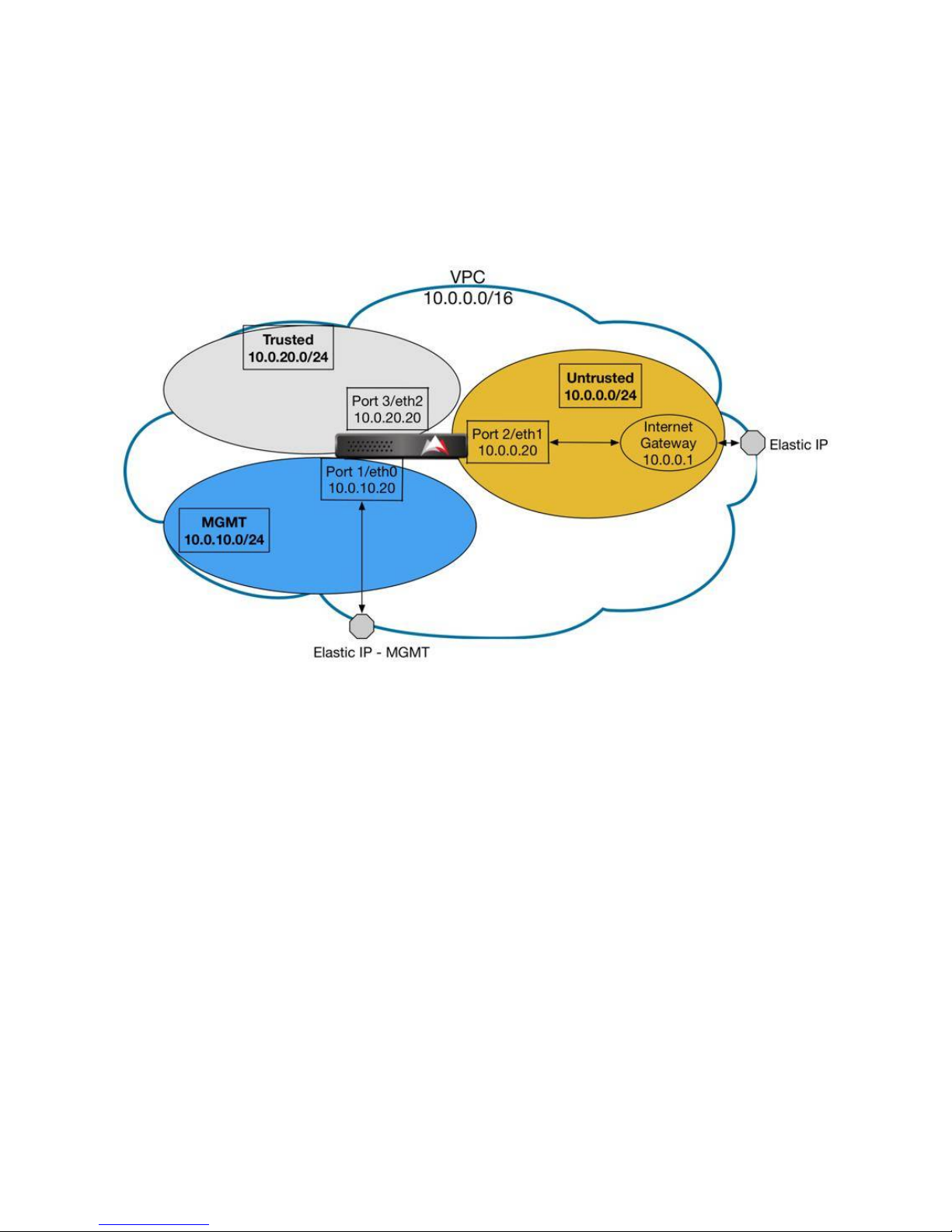
Design the Network Topology
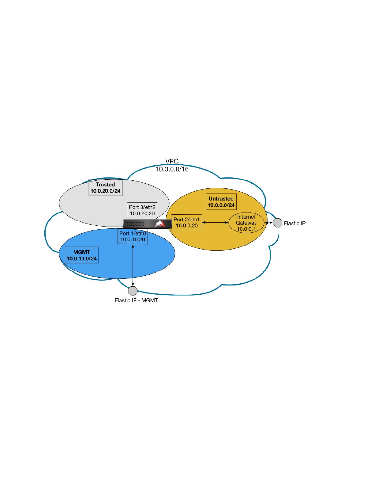
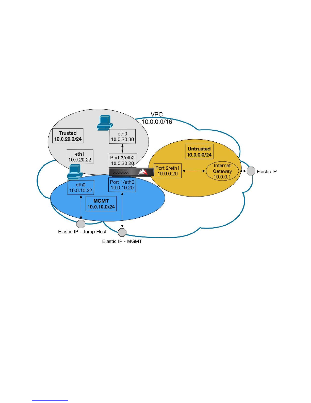
The following configurations are used as the basis for the procedures outlined in this document.
It is used for illustration purposes only. All host names and network addresses contained in this
guide are not intended to be representative of any real entity outside the scope of this guide or
test lab environment.
Figure 2.1 – Sample AMI Instance Topology Using BlackRidge BR-2120 Gateway for AMS
19
Page 21

VIRTUAL MACHINE
GATEWAY OS
PORT
LOGICAL PORT ASSIGNMENT
BlackRidge BR-2120
Gateway for AWS
BlackRidge
Release 3.0
Port 1
M: Management
Port 2
U: Untrusted
Port 3
T: Trusted
Port Assignments for the BR-2120 Gateway for AWS
The following table contains the Ethernet port assignments on the BlackRidge BR-2120
Gateways for AWS.
Table 2.2– Port Assignment for BlackRidge BR-2120 Gateways
The M port can be used only after it has been configured by the Setup Wizard through the
vSphere, or web client, and virtual console port. Thereafter, an SSH client, (PuTTY or equivalent)
connection can be used to perform advanced administration through its command line
interface (CLI).
The U port must be used to connect the gateway to untrustworthy networks (for example,
intranet and Internet). No network endpoint connected to these networks, are ever aware of
the high-value assets that are protected by BlackRidge gateways—they are effectively cloaked.
As a result, they are unable to establish TCP/IP connections to these Protected Resources.
The T port must be used to connect the gateway to the network endpoints (for example,
laptops and PCs) that are deemed trustworthy. These Trusted Hosts are configured with the
proper access and authorization rights to establish TCP/IP connections to the high-value,
networked assets (for example, servers for payroll, accounting and intellectual property)
protected by BlackRidge gateways.
Note: For the BlackRidge AWS GW the Management port M, DHCP is set by default.
20
Page 22

SECTION III
21
Page 23
Create and Configure Virtual Private Cloud
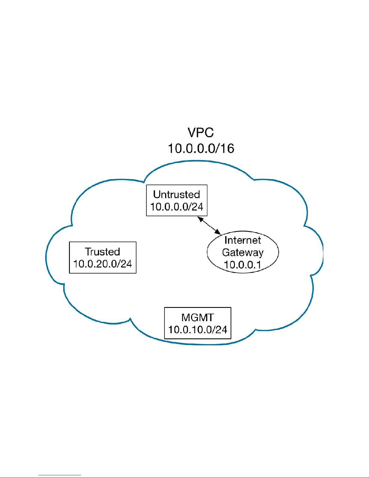
This section describes the creation of a Virtual Private Cloud (VPC) in AWS, along with the
following components:
Internet Gateway - Provides external access for internal components.
Subnets – Splits VPC into different zones (Trusted, Untrusted and Management subnets)
Route Tables - Defines routing paths inside the VPC.
Security Groups - Applies inbound and outbound traffic rules to the subnets.
22
Page 24
Task: Create VPC
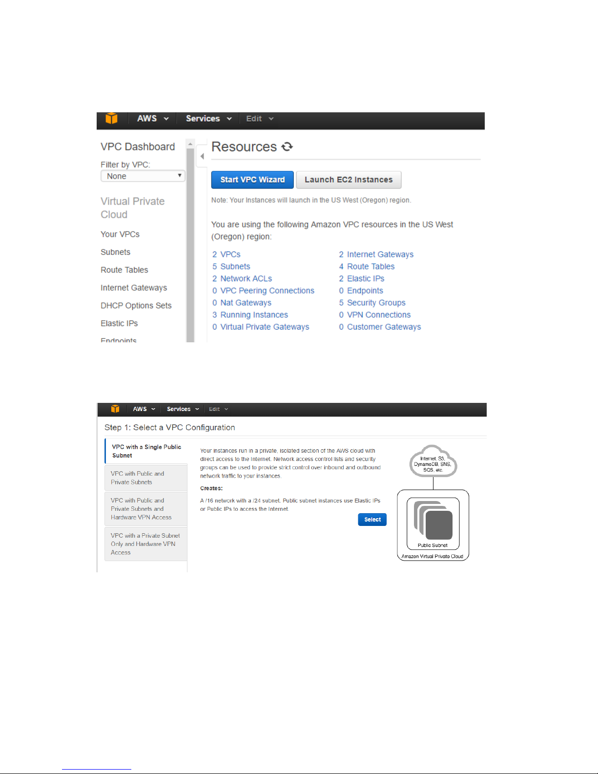
1. Using the upper left menu, navigate to Services > VPC.
2. Click Start VPC Wizard.
3. Select VPC with a Single Public Subnet, then click Select.
23
Page 25
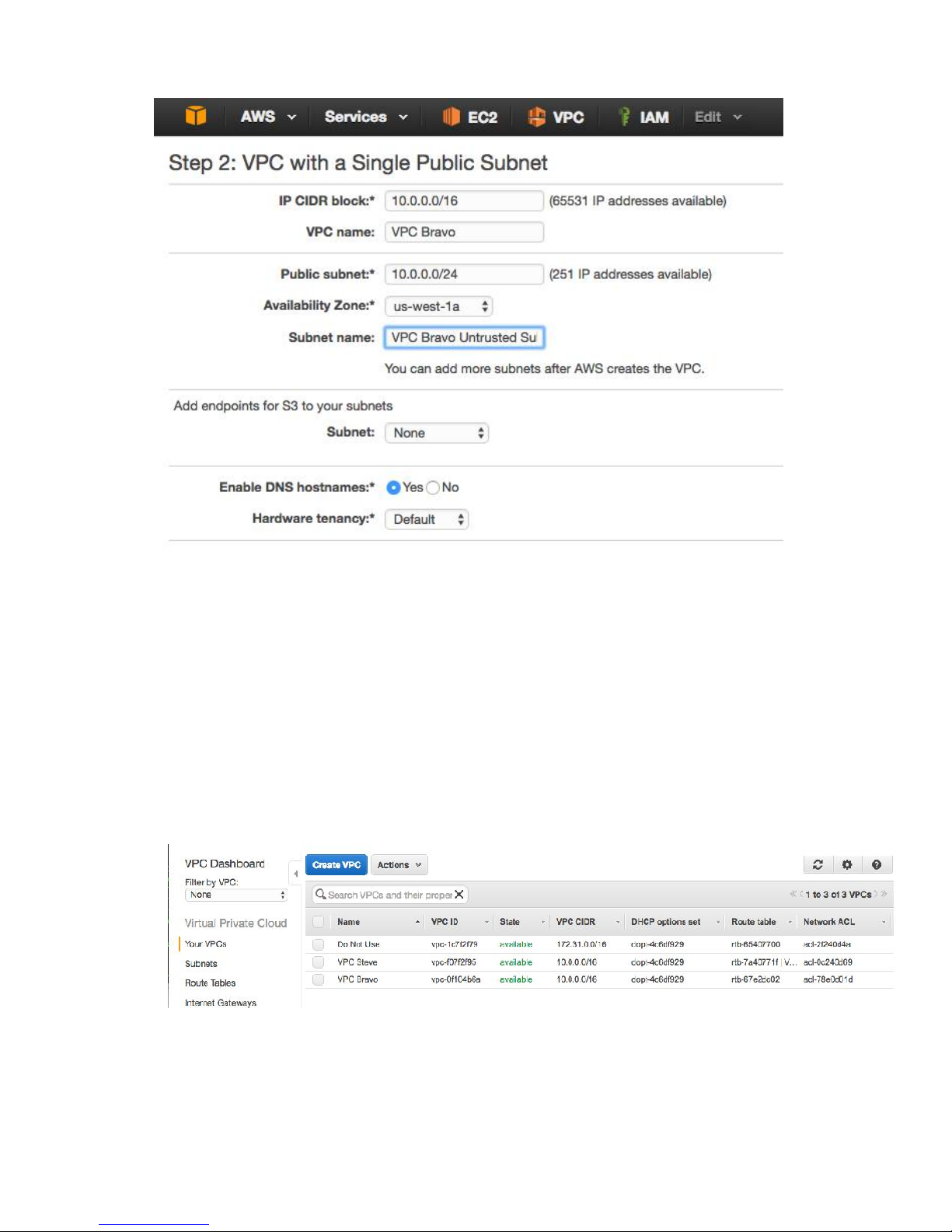
4. Configure the following options:
a. IP CIDR block – Use the default (10.0.0.0/16).
b. VPC name – Set as required (for example, VPC Bravo).
c. Public subnet – Use the default (10.0.0.0/24).
d. Availability Zone – Select the region in which all instances and subnets will
reside.
e. Subnet name – Set as required (for example, VPC Bravo Untrusted Subnet).
5. Use the defaults for the remaining fields, and click Create VPC.
6. Click OK after confirming the VPC was created successfully.
7. In the Your VPCs screen, locate the default VPC (the one that isn’t named).
8. Click the Name field for that row, and name the VPC Do Not Use.
Task: Configure Internet Gateway
1. In the left hand menu, click Internet Gateways.
24
Page 26
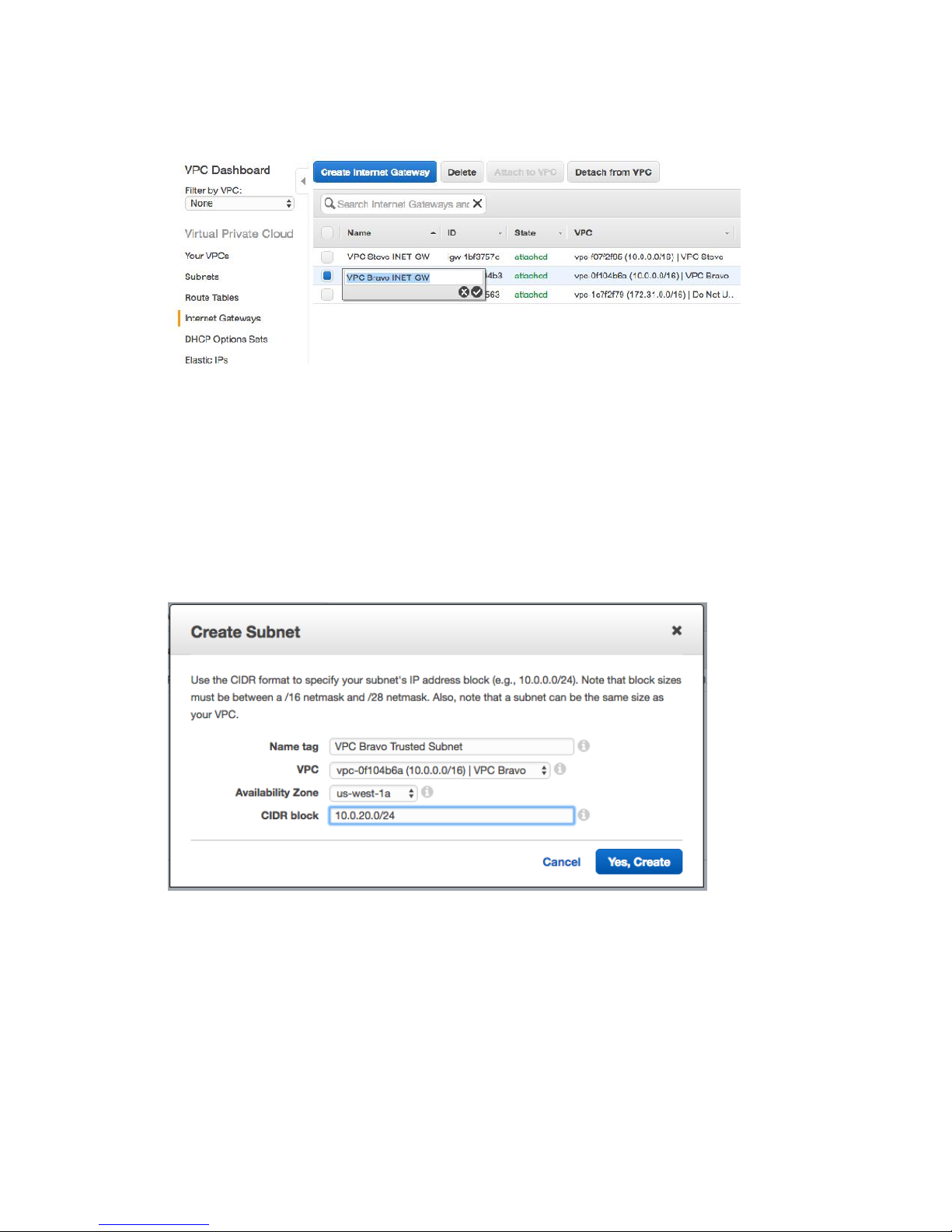
2. Find the entry created for your VPC in the VPC column.
3. Click the Name field for that row and name it (example: VPC Bravo INET GW).
Task: Create Subnets
1. In the left hand menu, click Subnets.
2. Verify that the subnet created when the VPC was created is present.
3. Click Create Subnet to create a subnet for the private/trusted subnet.
4. Configure the following options:
a. Name tag – Set as required (for example, VPC Bravo Trusted Subnet).
b. VPC – Select your VPC.
c. Availability Zone – Use the default.
d. CIDR block – Set the IP range to use on the private/trusted subnet as required
(for example, 10.0.20.0/24).
5. Click Yes, Create.
6. Click Create Subnet to create a subnet for the Management subnet.
25
Page 27
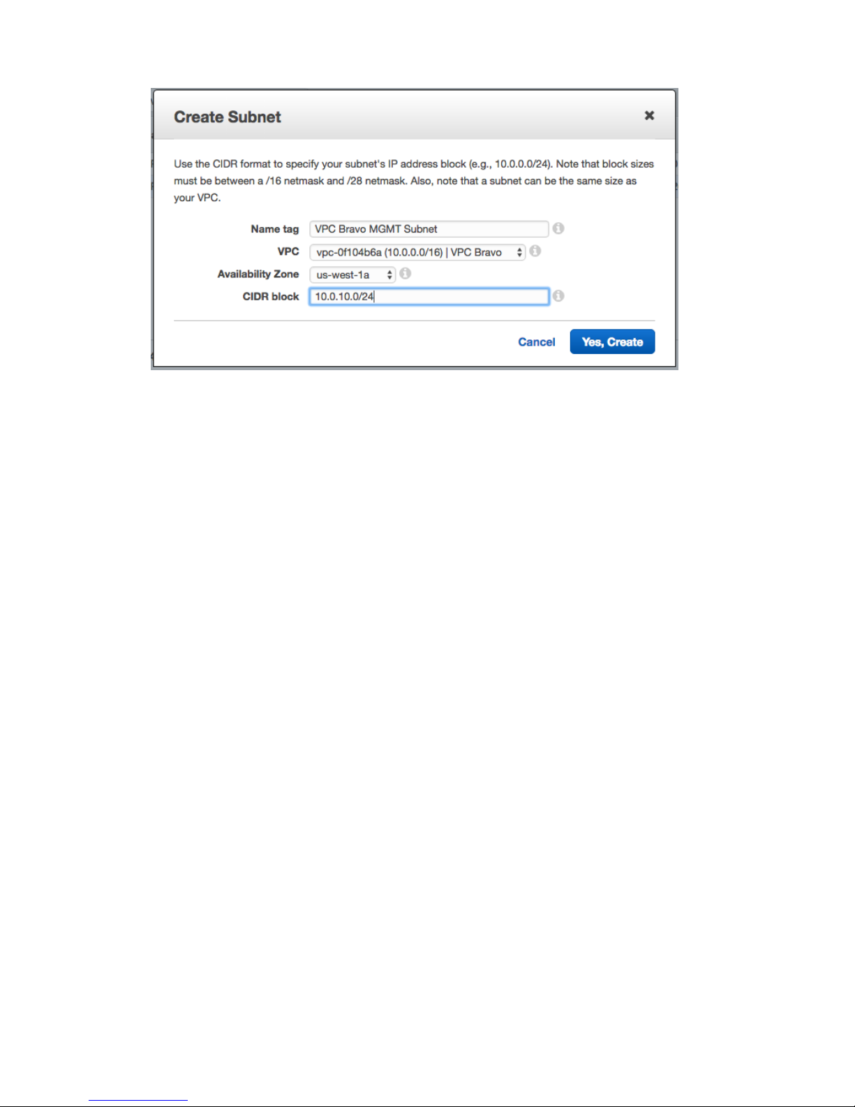
7. Configure the following options:
a. Name tag – Set as required (for example, VPC Bravo MGMT Subnet).
b. VPC – Select your VPC.
c. Availability Zone – Use the default.
d. CIDR block – Set IP range to use on the management subnet as required (for
example, 10.0.10.0/24).
8. Click Yes, Create.
26
Page 28
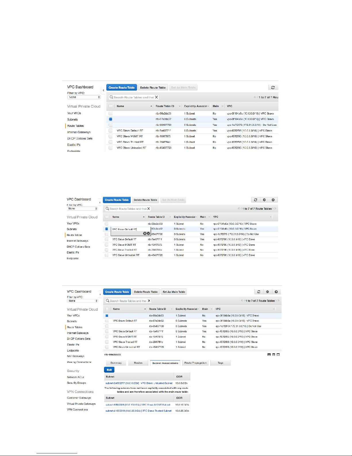
Task: Create Route Tables
1. In the left hand menu, click Route Tables.
2. Click the Name column to sort the table so that entries with blank names appear at the
top.
3. Locate the row with blank name that also has a value of Yes in the Main column (it
should also have 0 Subnets). Click the Name field for this row, and name it (for
example, VPC Bravo Default RT).
4. Click the other row with the Name column blank, and click the Subnet Associations tab
that populates at the bottom of the page
5. Verify that the Untrusted Subnet has been associated with this Route Table.
27
Page 29
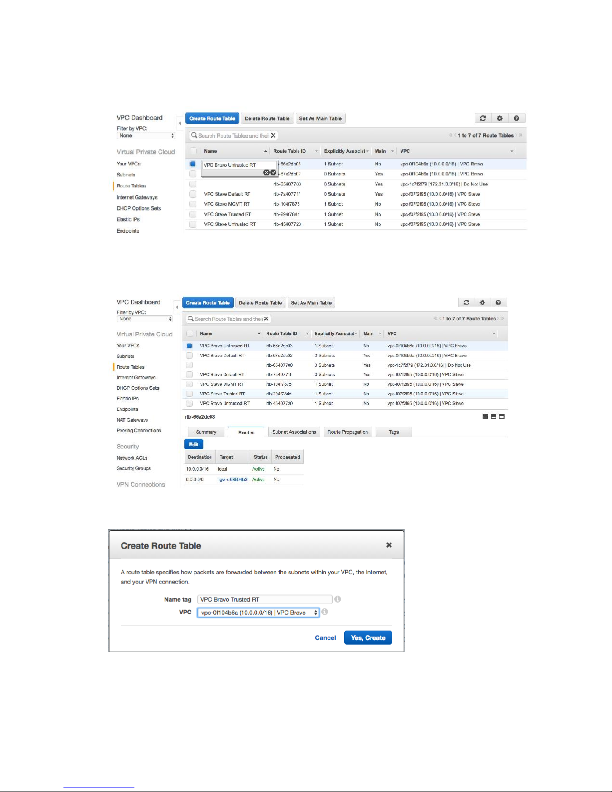
6. Click in the Name field for this Route Table row, and name appropriately (example: VPC
Bravo Untrusted RT).
7. Click the Routes tab at the bottom of the screen, and verify that this Route Table has a
route for the INET Gateway (the Destination = 0.0.0.0/0 entry per below).
8. Click Create Route Table to do so for the Trusted subnet.
9. Configure the following options:
a. Name tag – Set as required (for example, VPC Bravo Trusted RT).
b. VPC – Your VPC.
10. Click Yes, Create.
28
Page 30
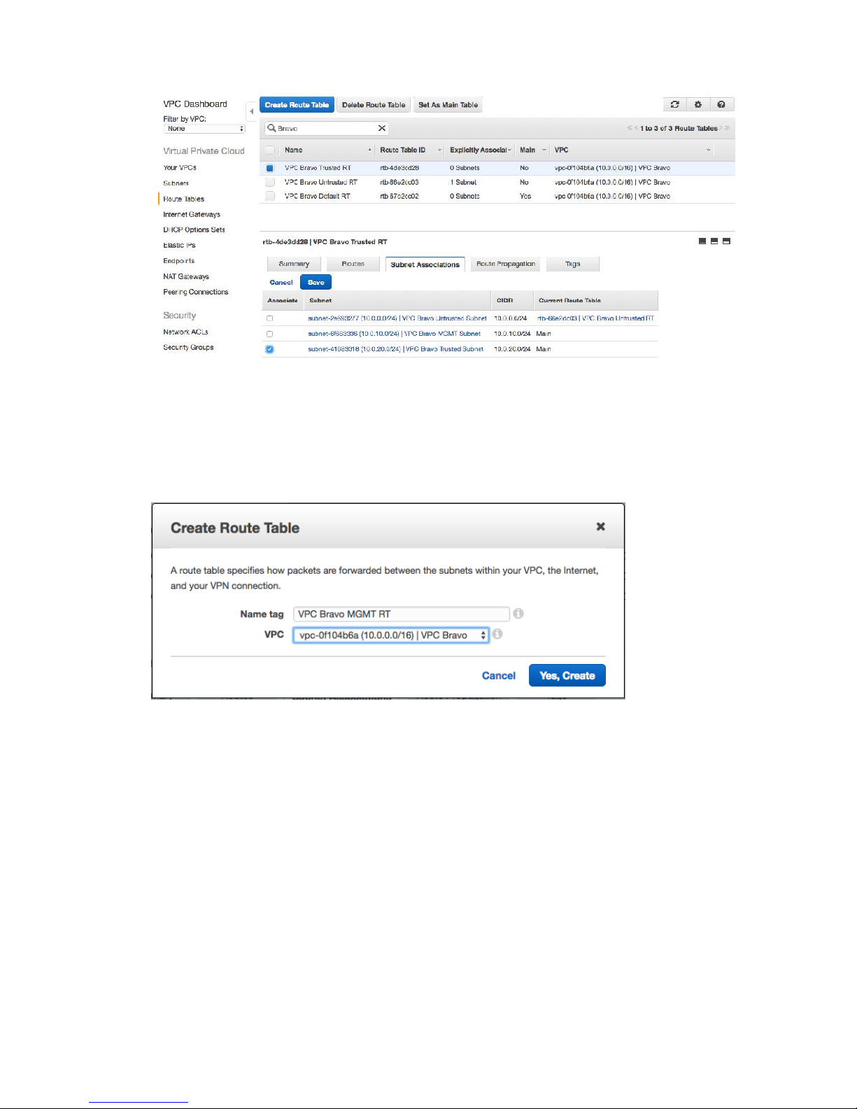
11. Select the Trusted Route Table, and click the Subnet Associations tab at the bottom of
the page.
12. Click Edit, and select the check box next to the Trusted Subnet entry.
13. Click Save.
14. Click Create Route Table to create a route table for the MGMT subnet.
15. Configure the following options:
a. Name tag – set as desired (for example, VPC Bravo MGMT RT).
b. VPC – Your VPC.
29
Page 31
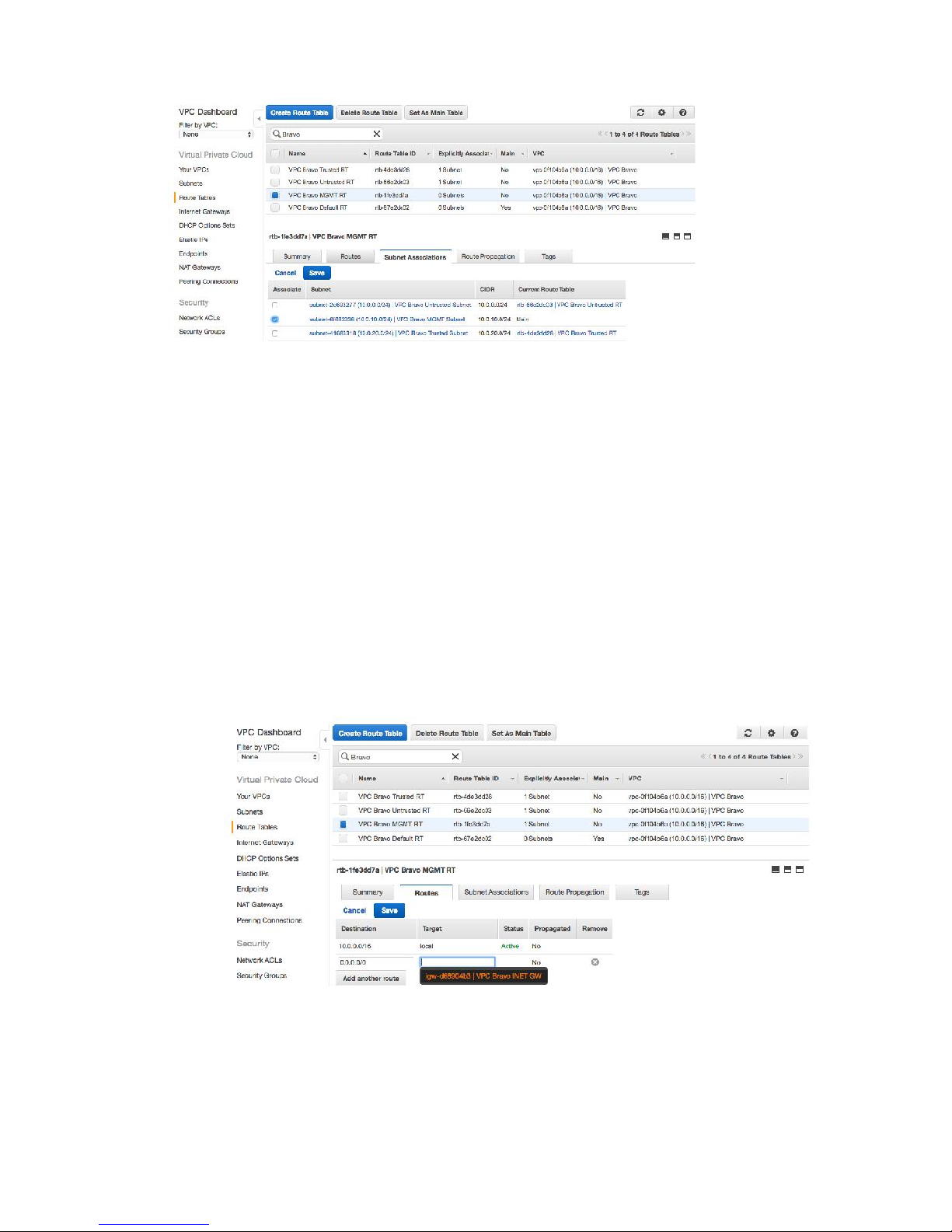
16. Select the Trusted Route table, and click the Subnet Associations tab at the bottom of
the page.
17. Click Edit, and select the check box next to the MGMT Subnet entry.
18. Click Save.
Task: Create Route Under the MGMT Route Table
1) Select the MGMT Route table entry, and click the Routes tab at the bottom of the
screen.
2) Click Edit, and configure the following values in the next empty input row:
a. Destination – 0.0.0.0/0
b. Target – Clicking in this box should bring up the ID for your INET GW. Select this
value.
c. Click Save.
30
Page 32
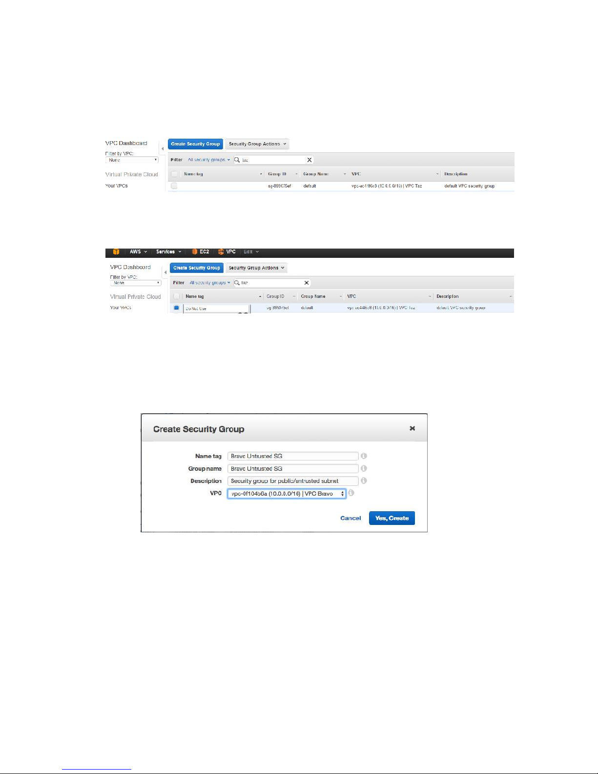
Task: Create Security Groups
1. In the left hand menu under VPC Dashboard, click on Security Groups (under Security
heading).
2. For any pre-existing entries with blank “Name tag” fields, click on the “Name tag” field
and input “Do Not Use” (as we’ll be creating new security groups).
3. Click on the Security Group button, and create a group for the Untrusted subnet.
a. Name tag – set as desired (example: VPC Bravo Untrusted SG)
b. Group name – same as Name tag
c. Description – set as desired
d. VPC – your VPC
4. With the Untrusted Security Group selected, click on the Inbound Rules tab at the
bottom, then click Edit.
5. Configure a rule with the following settings, then click Save.
a. Type – ALL Traffic
b. Protocol – ALL
c. Source - 0.0.0.0/0
31
Page 33
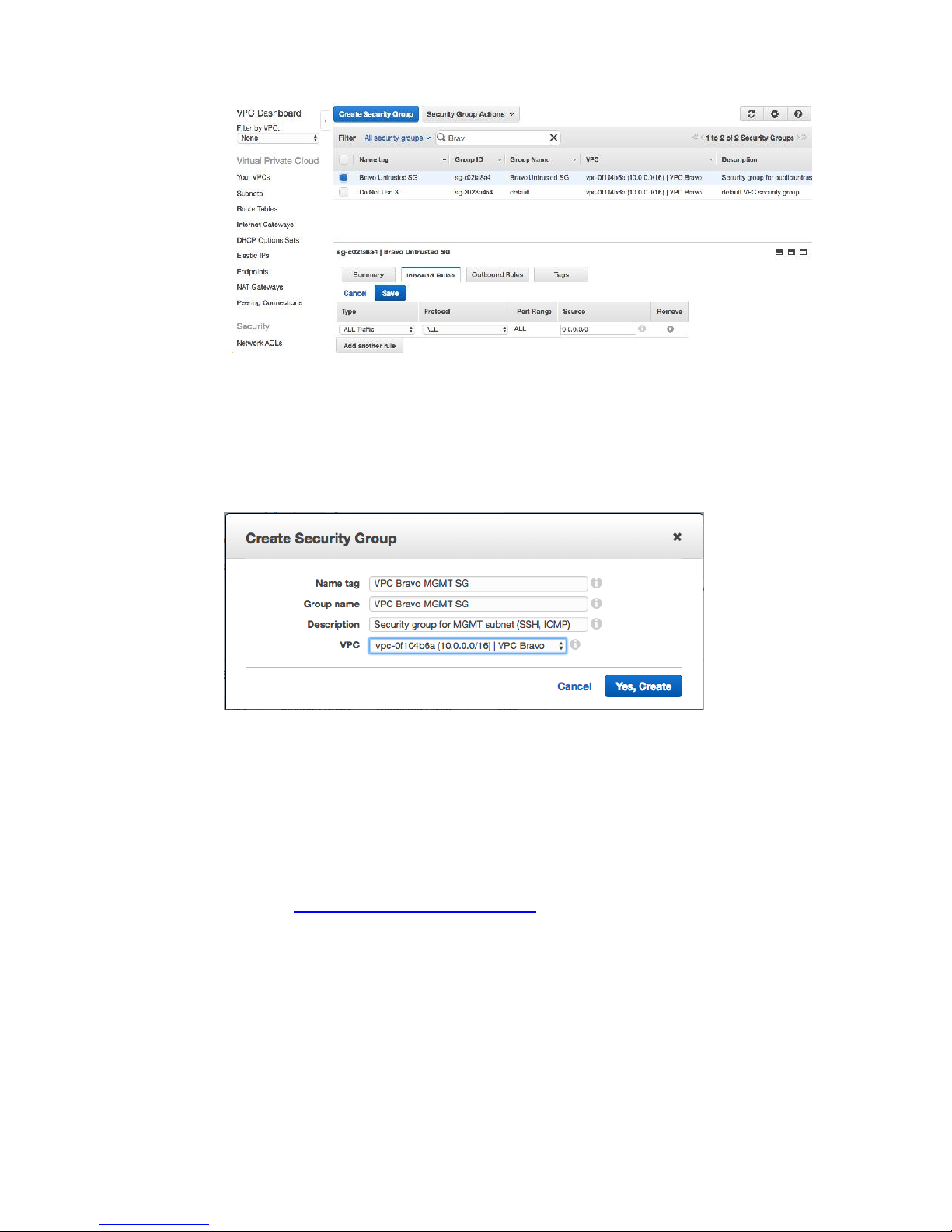
6. Click on the Security Group button, and create a group for the MGMT subnet.
a. Name tag – set as desired (example: VPC Bravo MGMT SG)
b. Group name – same as Name tag
c. Description – set as desired
d. VPC – your VPC
7. With the MGMT Security Group selected, click on the Inbound Rules tab at the bottom,
then click Edit.
8. Configure a rule with the following settings, then click Save.
a. Type – SSH
b. Protocol – TCP (6)
c. Source – <Your IP Address>/32
i. As you are likely on an internal network yourself, use a site like
http://whatismyipaddress.com/ to determine your public address.
ii. This setting will restrict SSH access to the MGMT port of the GW to
ONLY traffic from the IP address you specify here.
9. Configure another rule with the following settings, then click Save.
a. Type – ICMP
b. Protocol – ICMP (1)
c. Source – 0.0.0.0/0
32
Page 34
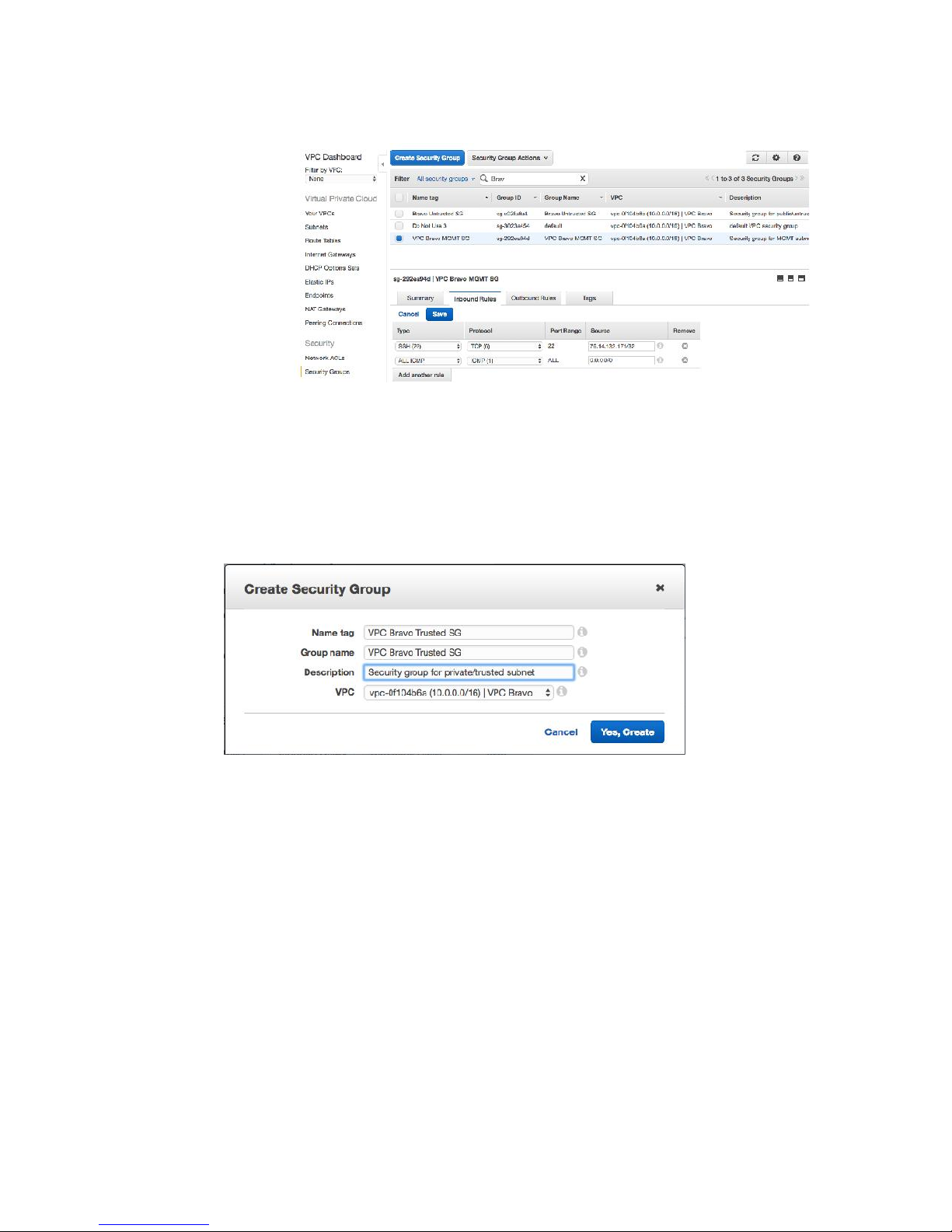
i. This setting will allow ICMP access from any IP address.
10. Click on the Security Group button, and create a group for the Trusted subnet.
a. Name tag – set as desired (example: VPC Bravo Trusted SG)
b. Group name – same as Name tag
c. Description – set as desired
d. VPC – your VPC
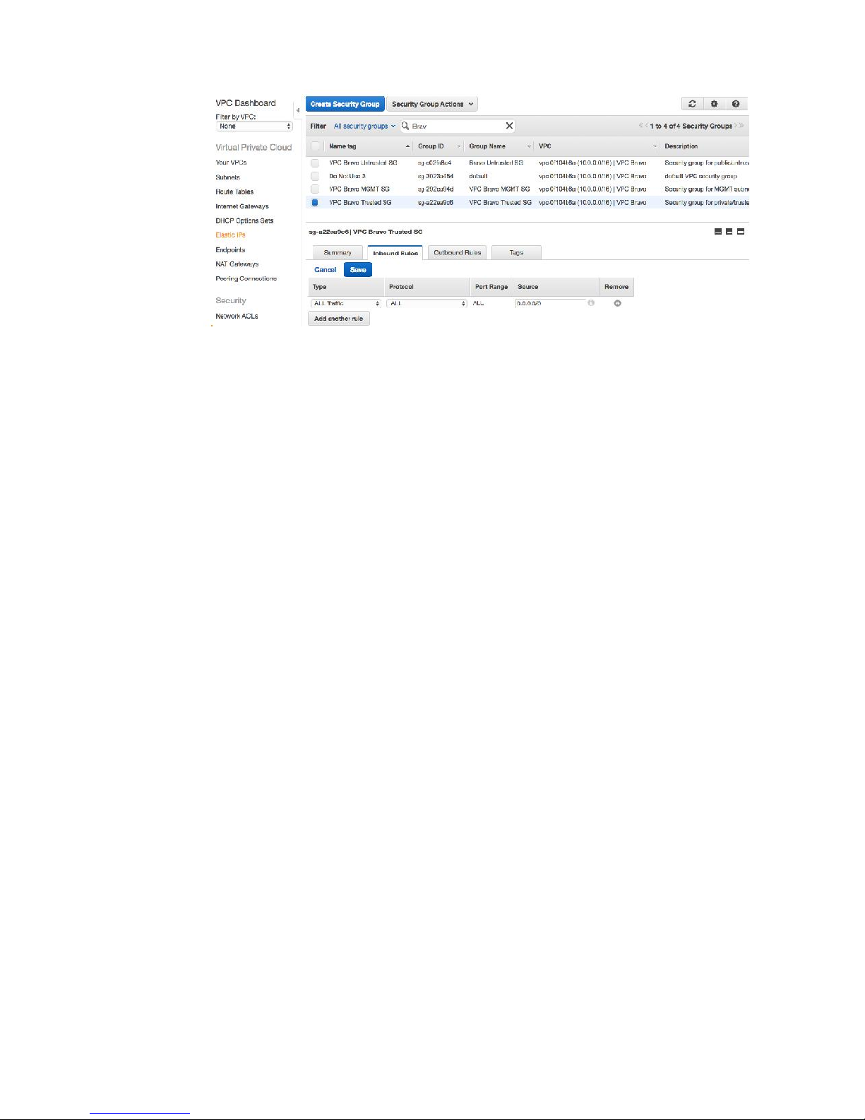
11. With the Trusted Security Group selected, click on the Inbound Rules tab at the bottom,
then click Edit.
12. Configure a rule with the following settings, then click Save.
a. Type – All Traffic
b. Protocol – ALL
c. Source – 0.0.0.0/0
33
Page 35
34
Page 36

SECTION IV
35
Page 37
Launch and Configure a Gateway AMI Instance
This section describes how to deploy and configure a BRT TAC Gateway instance from AMI into
a VPC. After initial configure and deployment of a Gateway instance with one interface, the
rest of the interfaces will be added and configured one-by-one as appropriate. Two (2) Elastic
IPs will be created and associated with the appropriate interfaces:
Untrusted - to provide inbound and outbound access to trusted hosts/protected
resources
MGMT - to provide external access to the Management port of the Gateway (protected
by Inbound rules in the MGMT Security Group).
Task: Configure and Launch an AMI Instance
1. Click on the orange cube in the upper left corner of the web UI, then click on EC2 (under
Compute).
2. In the left hand menu, under the Images header, click on AMIs.
36
Page 38
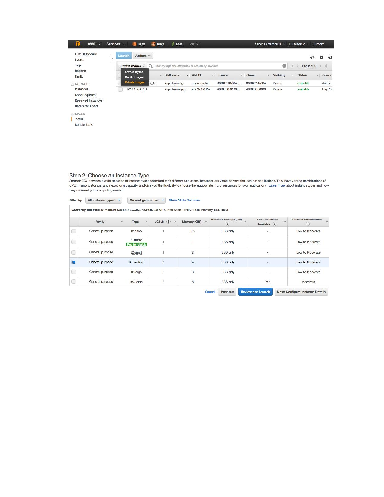
3. With your AMI selected, click on the Launch button.
4. Choose the “t2.medium” instance type on the next screen (to ensure support for 3
NICs), and click on the “Next: Configure Instance Details” button at the far right.
5. On the next screen (Step 3), configure the following values:
a. Network – select your VPC
b. Subnet – select your Management subnet
c. Auto-Assign Public IP – select Disable
i. An Elastic IP will be configured later to provide access to the MGMT
interface of the GW from the outside.
d. Under the “Network Interfaces” subsection towards the bottom of the page,
assign your own IP address if desired from the range specified in the Subnet
setting (example: 10.0.10.20)
i. You can also let AWS select the IP for you automatically if desired.
e. Click on the “Next: Add Storage” button at the far right.
37
Page 39
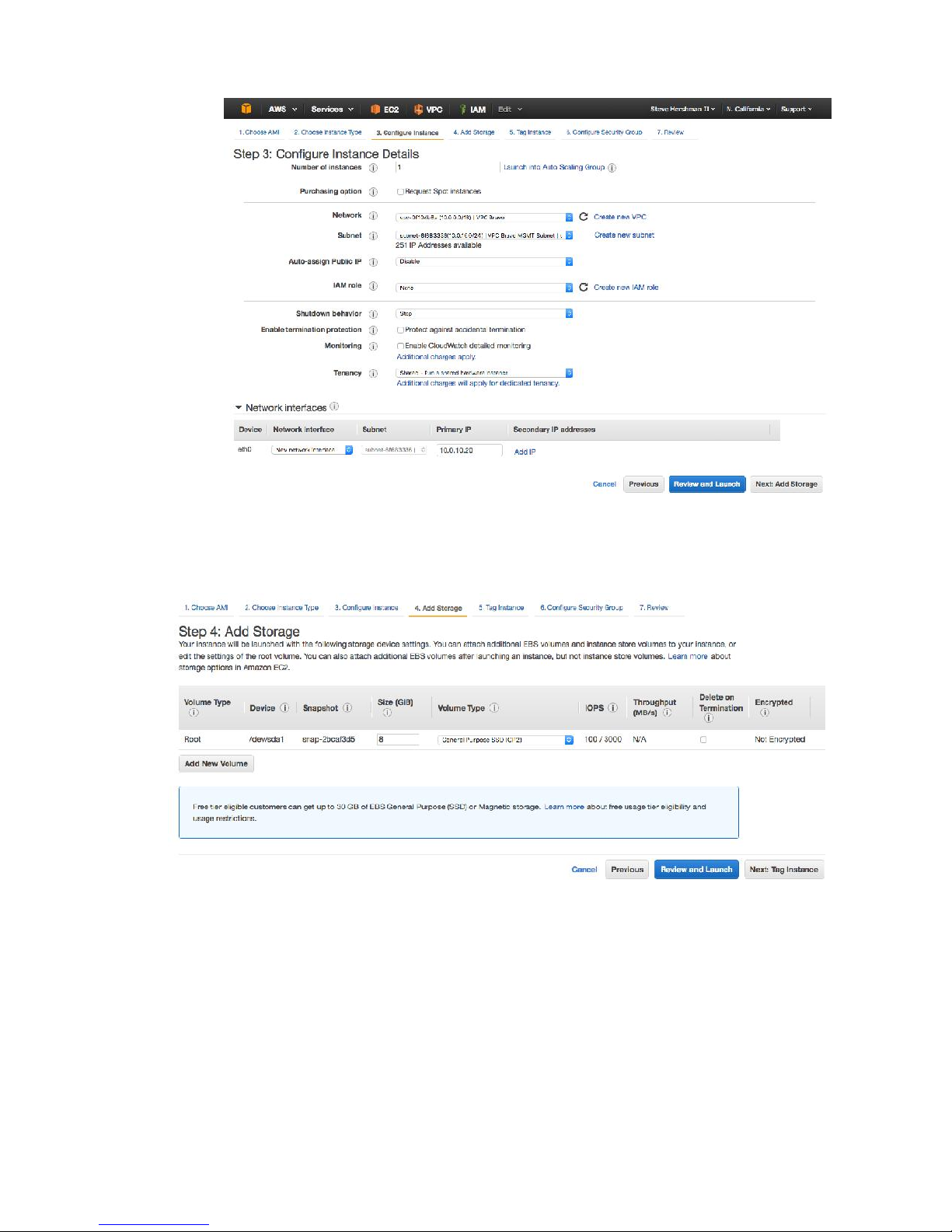
6. On the next screen (Step 4) accept the default settings and click on the “Next: Tag
Instance” button at the far right.
7. On the next screen (Step 5), name the instance as desired (e.g., “VPC Bravo BRT GW”),
then click on the “Next: Configure Security Group button”.
38
Page 40
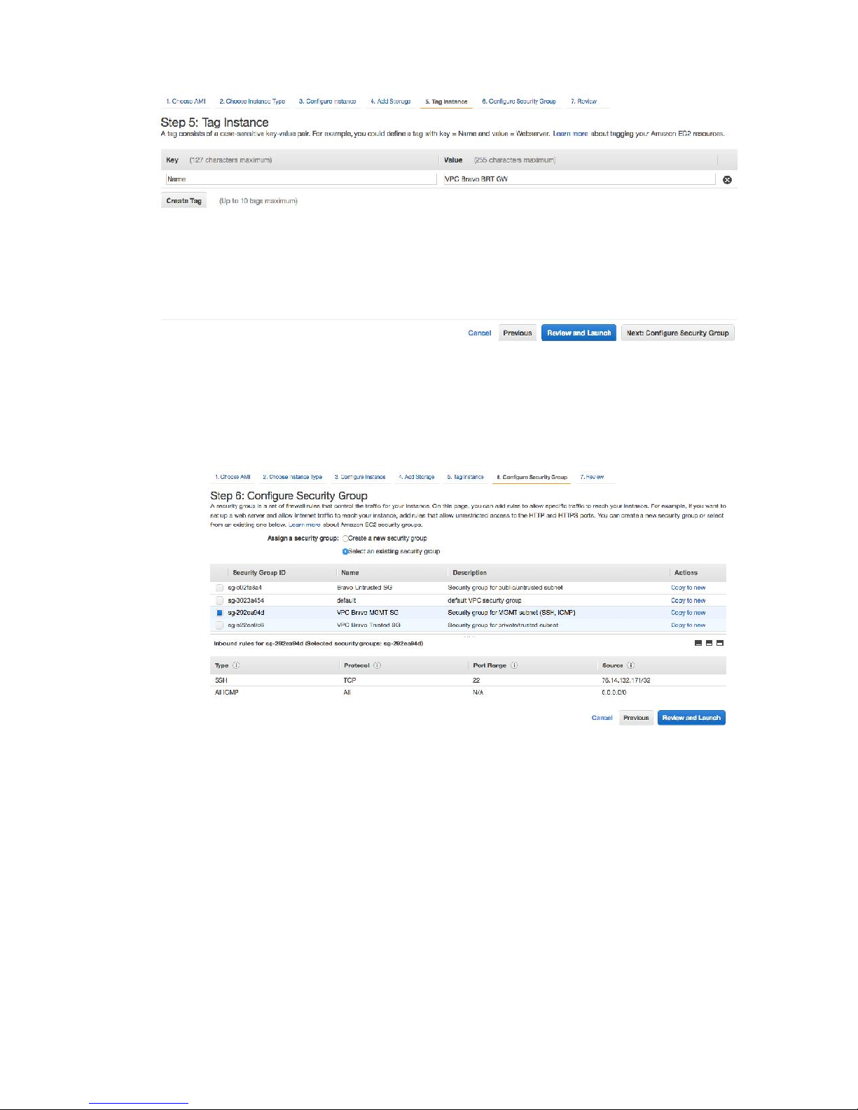
8. On the next screen (Step 6), do the following:
a. Under “Assign a security group:”, select the 2
security group”.
b. Select the checkbox next to the Management security group.
nd
radio button – “Select an existing
9. Click on the “Review and Launch” button.
10. The next screen will give a message about the instance not being eligible for the free
usage tier, and that the instance is open to the world. Proceed by clicking on the
“Launch” button.
39
Page 41
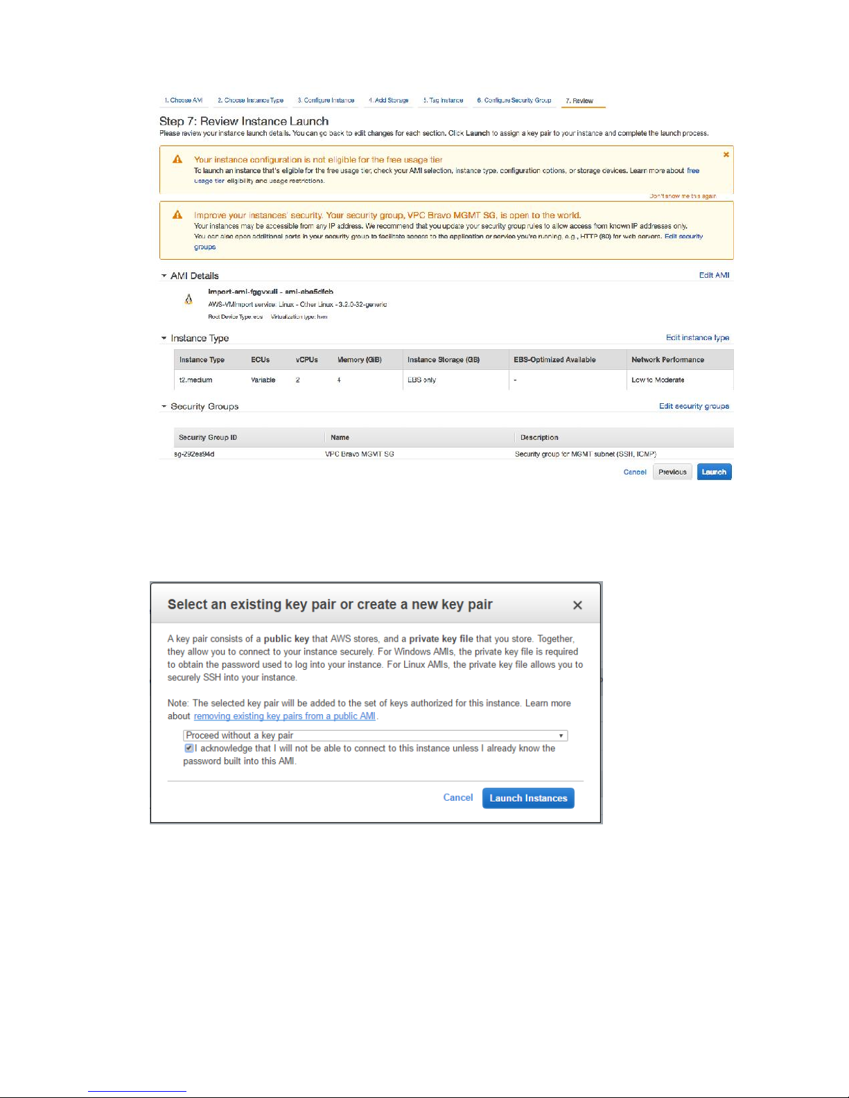
11. A popup will prompt for selection or creation of a key pair for accessing the instance. In
the dropdown, select the option “Proceed without a key pair”, click on the “I
acknowledge…” checkbox, and click on the “Launch” button.
12. On the next screen, click on “View Instances” (or “Instance” from the left hand menu).
The AMI instance will spend some time initializing (~15-20 minutes).
13. To check on the AMI instance status, select it in the Instance screen and use Actions ->
Instance Settings -> Get System Log.
40
Page 42
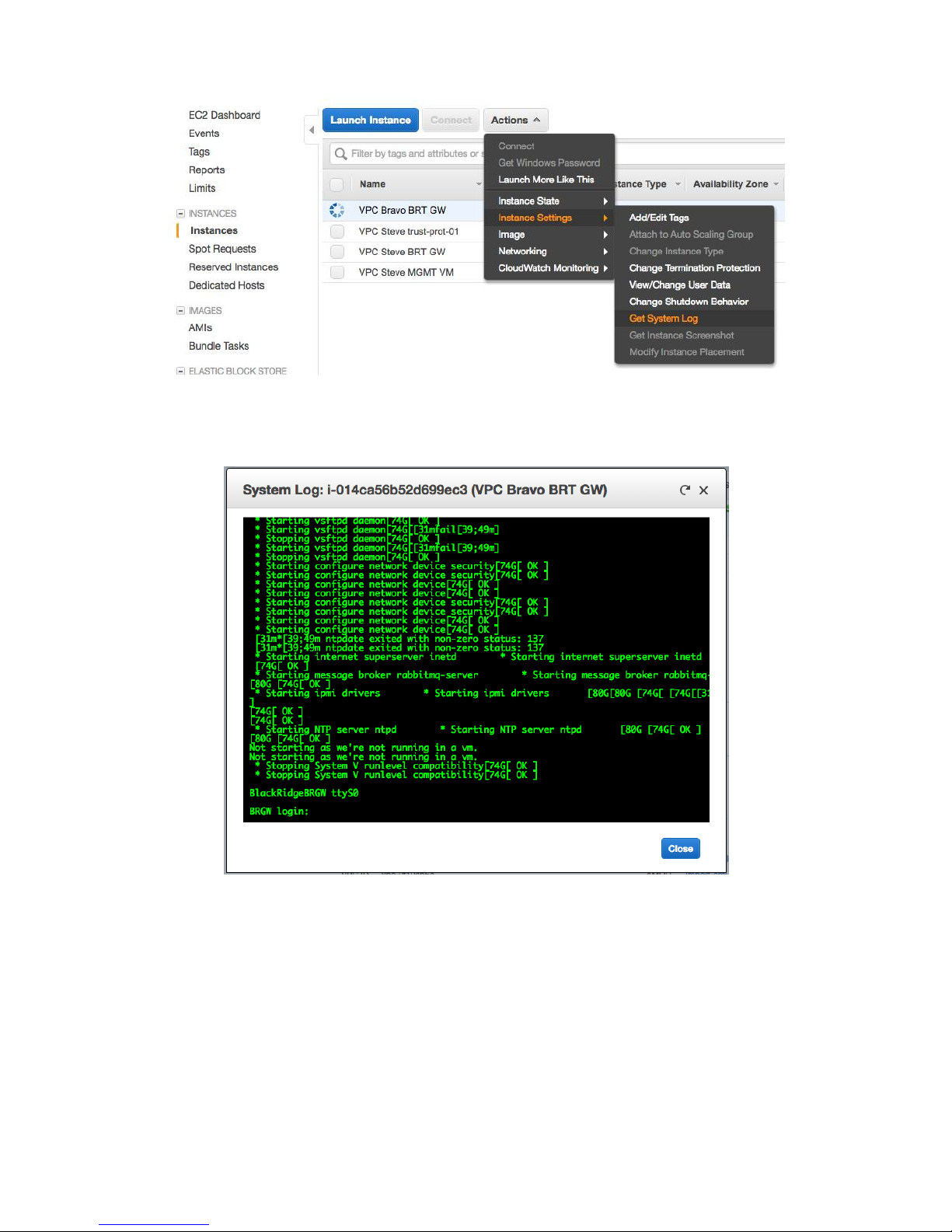
a. If the instance has completed booting, you should be able to scroll down in the
resulting popup and see the login prompt.
41
Page 43
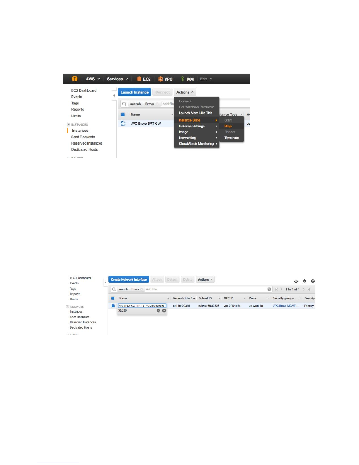
Task: Stop the AMI Instance
1. From the Actions button in the Instance screen, select -> Instance State -> Stop.
2. Verify the instance is stopped before proceeding.
Task: Review Settings of the eth0/Management Interface for the
AMI Instance
1. In the left hand menu, under the “Network & Security” heading, click on “Network
Interfaces”.
2. Locate the currently configured interface (corresponds to eth0/the MGMT port on the
Gateway), and click on the Name field to give it an appropriate name (example: VPC
Bravo GW Port 1 ETH0 Management).
3. With this interface selected, select Actions -> Change Security Groups, and select the
Management security group if not already selected.
42
Page 44
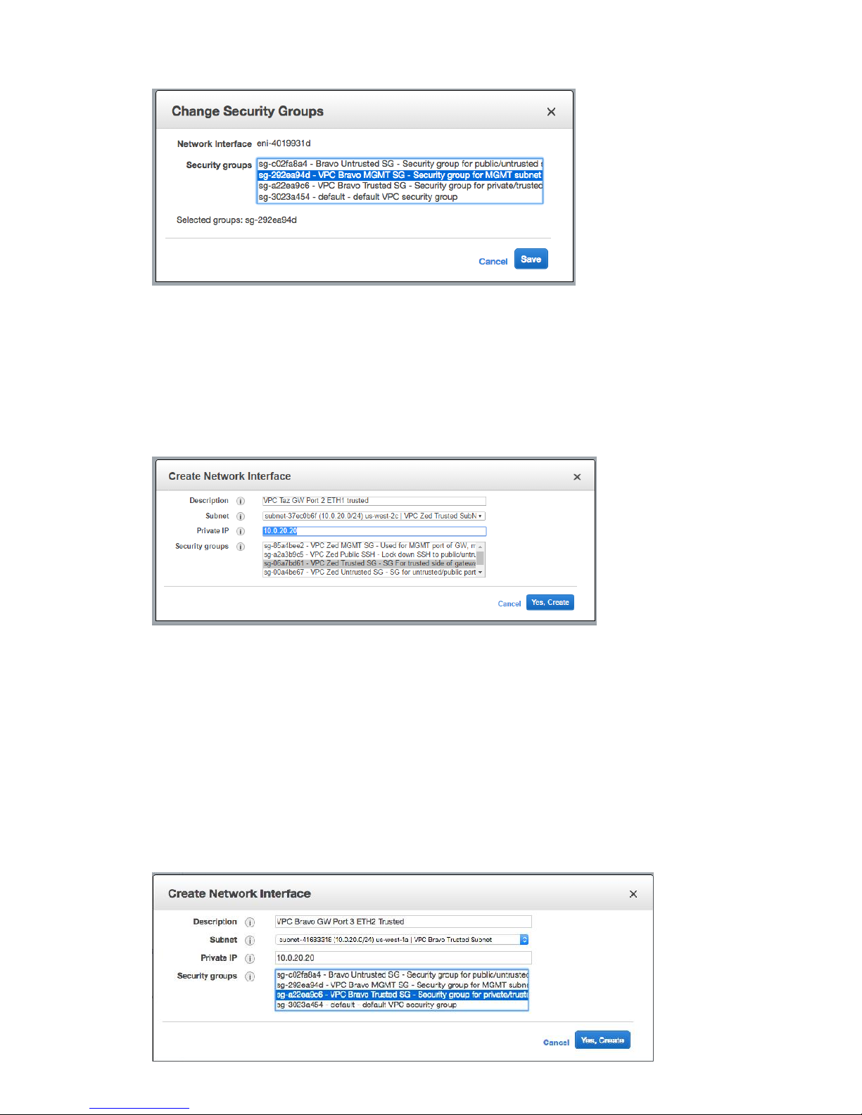
Task: Create Additional Interfaces for the AMI Instance
1. Click Create Network Interface.
2. Configure the following values, and click Yes, Create.
a. Description – set as desired (example: VPC Bravo GW Port 2 ETH1 Untrusted)
b. Subnet – Select the Trusted subnet.
c. Private IP – Set as required from the IP range for the Subnet (for example,
10.0.0.20). You can also let AWS select the IP for you automatically.
d. Security groups – Select the untrusted security group.
3. Back at the Instances screen, click in the Name field for the newly-created interface, and
input the same value used for Description above (for example, VPC Bravo GW Port 2
ETH1 Untrusted).
4. Click Create Network Interface.
43
Page 45
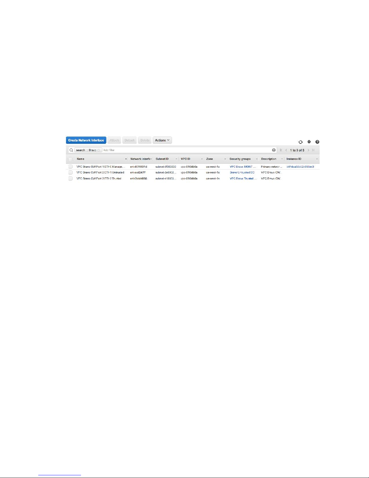
5. Configure the following values, and click Yes, Create.
a. Description – Set as required (for example, VPC Bravo GW Port 3 ETH2 Trusted).
b. Subnet – Select the Trusted subnet.
c. Private IP – Set as required from the IP range for the Subnet (for example,
10.0.20.20). You can also let AWS select the IP for you automatically.
d. Security groups – Select the trusted security group.
6. Back at the Instances screen, click in the Name field for the newly-created interface and
input the same value used for Description above (for example, VPC Bravo GW Port 3
ETH2 Trusted).
7. There should now be a total of three network interfaces, for which two have no Instance
ID assigned.
44
Page 46
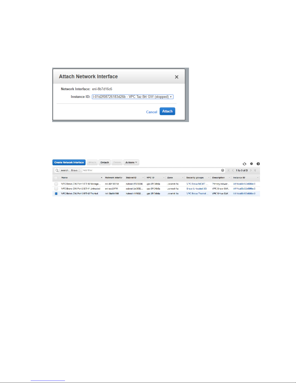
Task: Attach Additional Interfaces to the AMI Instance
1. From the Instances screen, select the row for Port2 ETH1 (the Untrusted port), and click
Attach at the top (or Actions > Attach).
2. At the popup, select the Instance ID, and click Attach.
3. Repeat for the Trusted Port. ORDER MATTERS!
4. When complete, all three interfaces will have the same Instance ID set.
45
Page 47
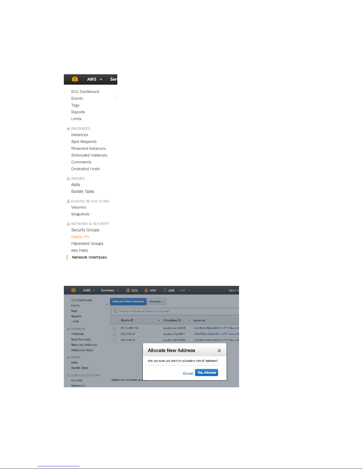
Task: Allocate a New Elastic IP Address for the MGMT Interface
1. In the left hand menu, select Elastic IPs under Network and Security.
2. Click Allocate New Address.
3. Click Yes, Allocate.
Note: You are limited to five free Elastic IPs. You will be charged for any additional IPs
above that number.
46
Page 48
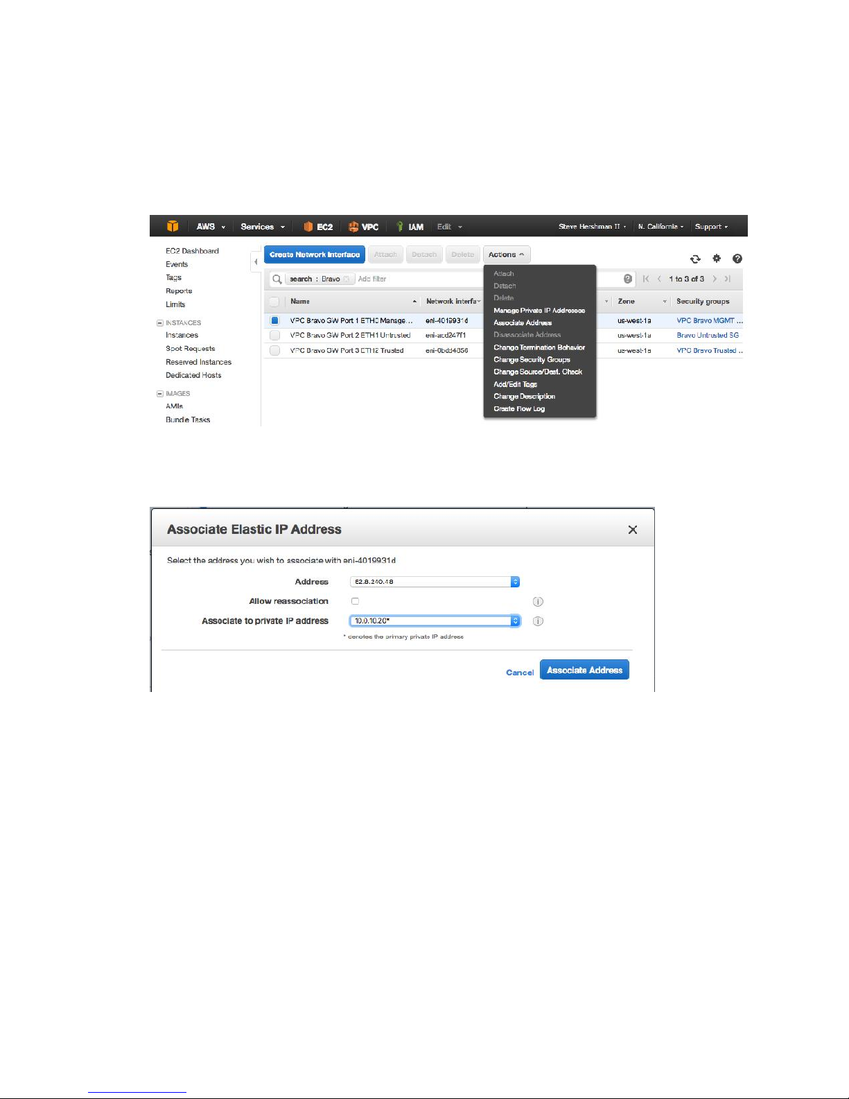
Task: Associate Elastic IP with MGMT Interface
1. In the left hand menu, select Network Interfaces to return to that screen.
2. Select the Management interface, then use the Actions button to perform the
“Associate Address”.
3. In the resulting popup, make sure that the newly-generated Elastic IP address is
matched with the Management interface address, then click “Associate Address”.
4. In the left hand menu, under the “Instances” heading, click on Instances.
5. Select your instance, then start it via Actions -> Instance State -> Start.
6. Wait for the instance to come up (can take a few minutes).
47
Page 49
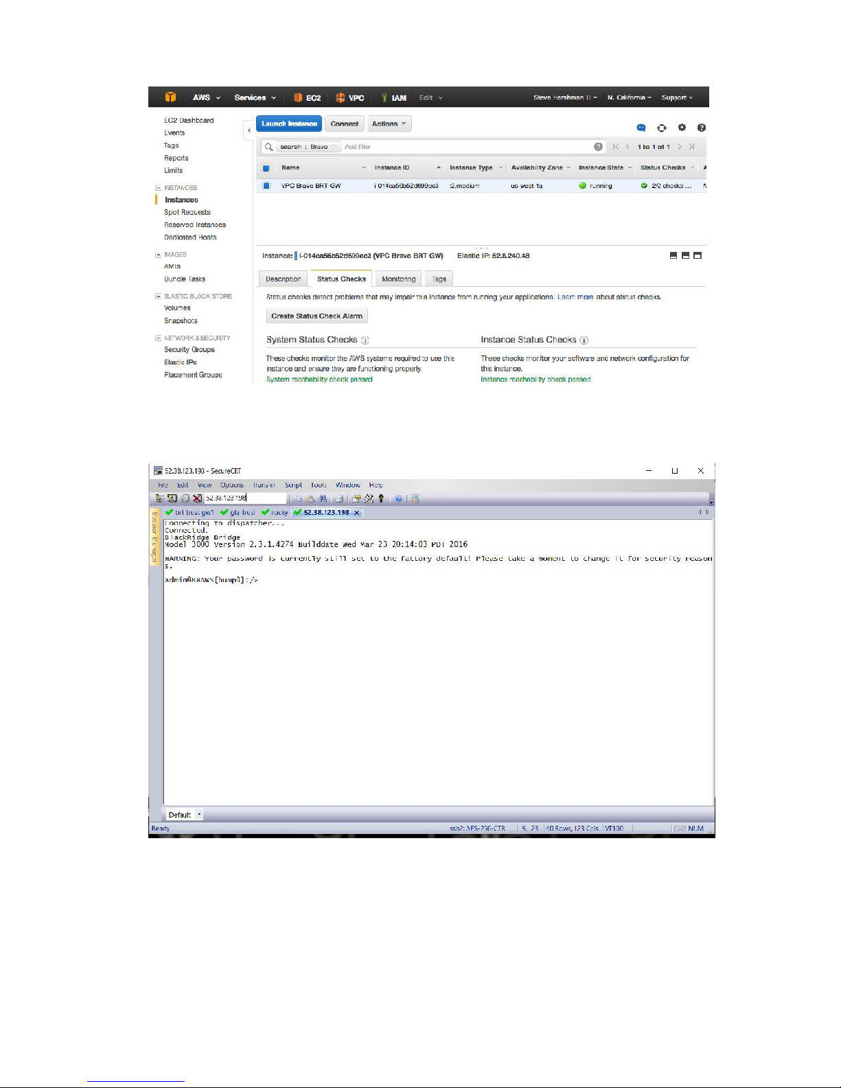
7. When running (as shown above), SSH to the Elastic IP address as the admin user. This
should result in traffic being forwarded to the Management interface on the Gateway.
8. At this point you may configure the GW as required, using the admin CLI and/or the
Setup Wizard:
a. Set hostname.
b. Change admin password.
c. Configure other options as required.
48
Page 50
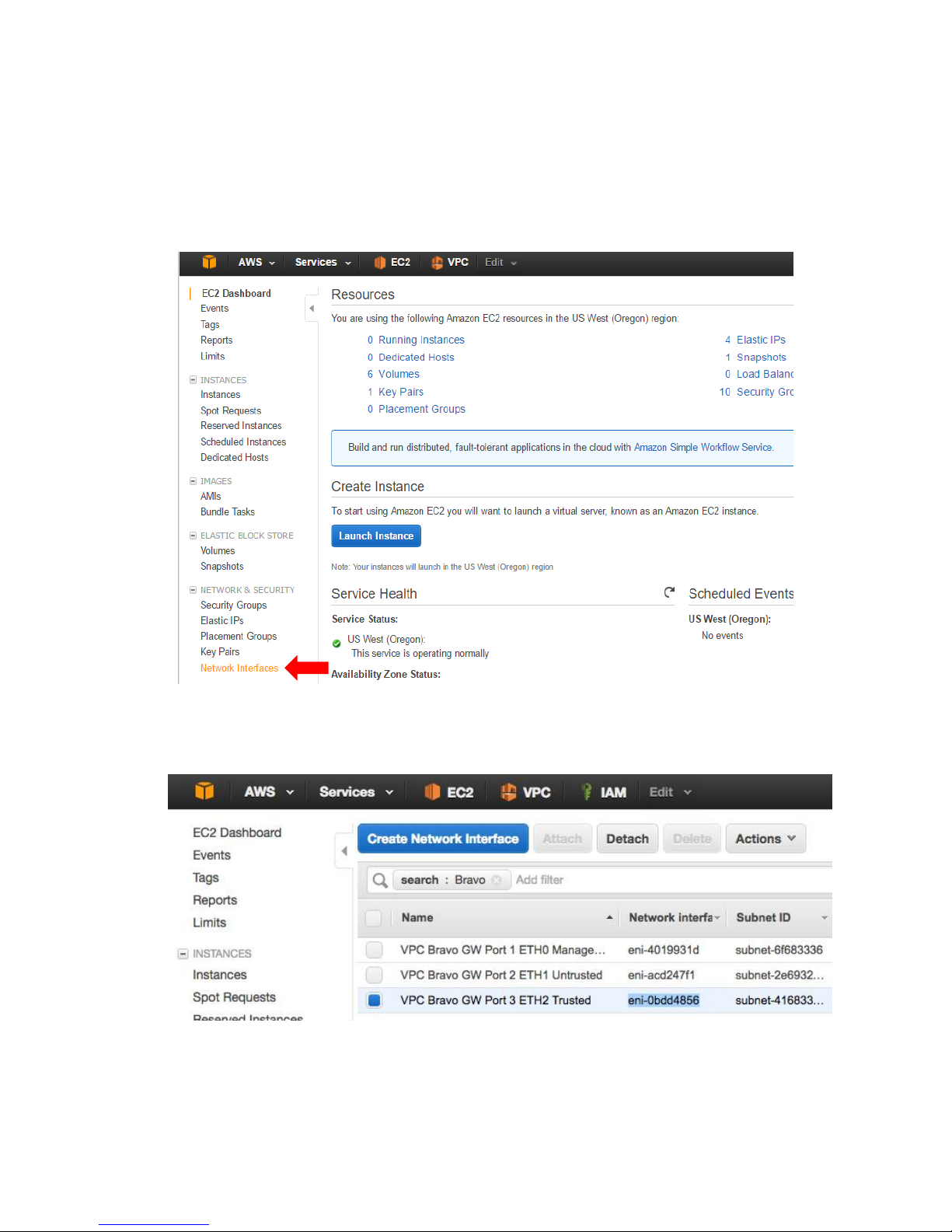
Task: Modify Route Table for (Trusted + Protected) Side of BRT
GW
1. In the web UI, from the EC2 Dashboard (Services -> EC2), select “Network Interfaces”
from the left hand menu.
2. Find the interface corresponding to Port 3 (eth2, the Trusted port) on the Gateway.
Copy the Network Interface ID value for that interface.
49
Page 51
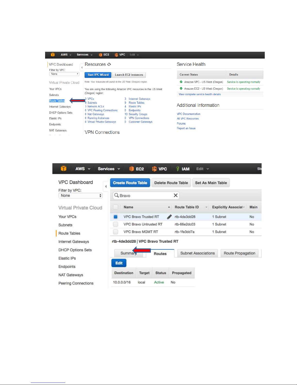
3. In the web UI, under the VPC Dashboard (Services -> VPC), click on “Route Tables” in the
left hand menu.
4. Locate the Trusted Route Table for your VPC and select it. In the Routes tab at the
bottom of the screen, click on the Edit button.
5. Click Add another route, and input the following values and click Save.
a. Destination - 0.0.0.0/0
b. Target - Paste in the Network Interface ID from earlier; this will perform a lookup
for the interface that you will then select.
50
Page 52
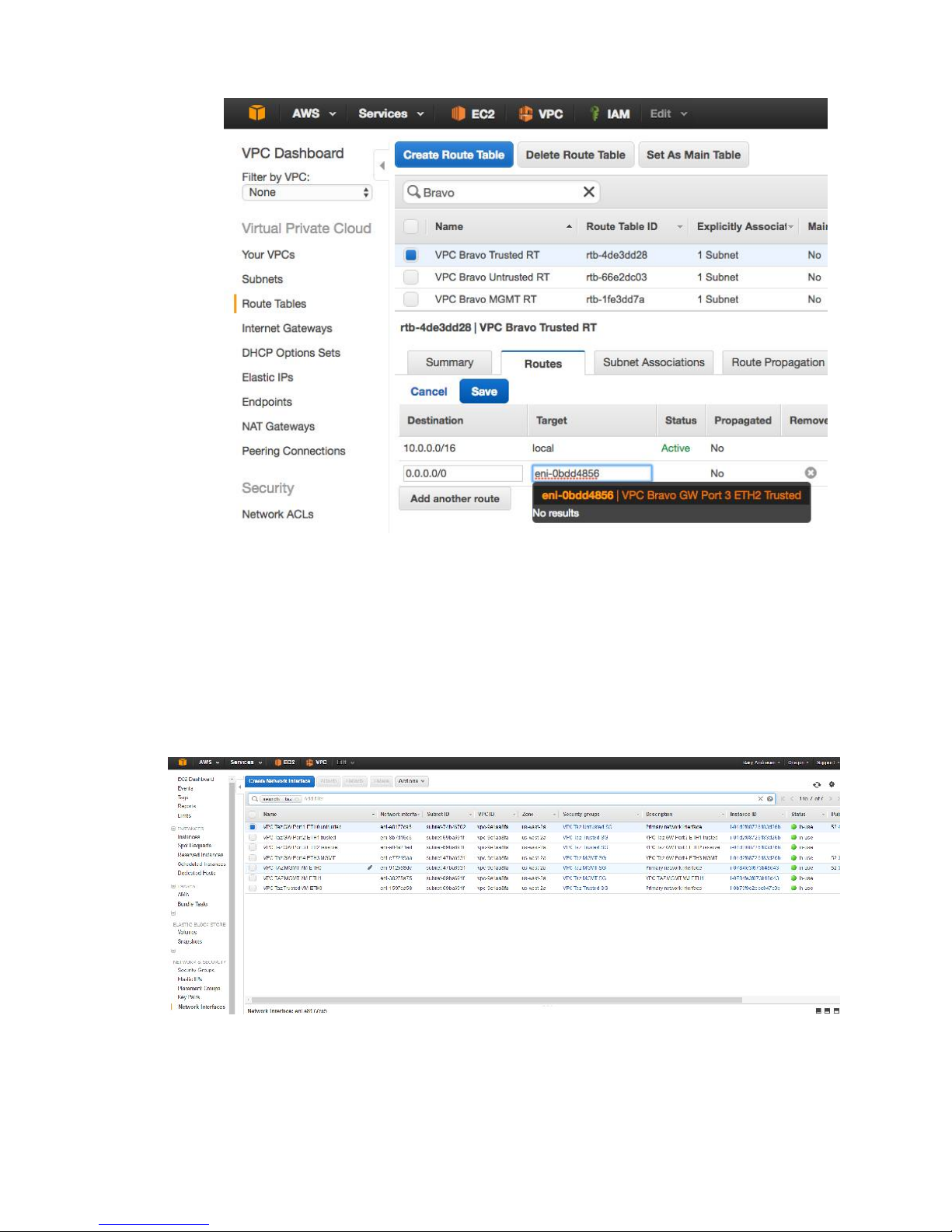
Note: The Status of the route you just added could say ‘Black Hole’. This happens when the
instance is currently down.
Task: Disable Source/Destination Check for Untrusted and
Trusted Interfaces
1. Go back to the EC2 Dashboard, and select Network Interfaces under Network &
Security.
2. Locate the entry for the Gateway’s Untrusted interface. Right-click, and select Change
Source/Dest. Check.
51
Page 53
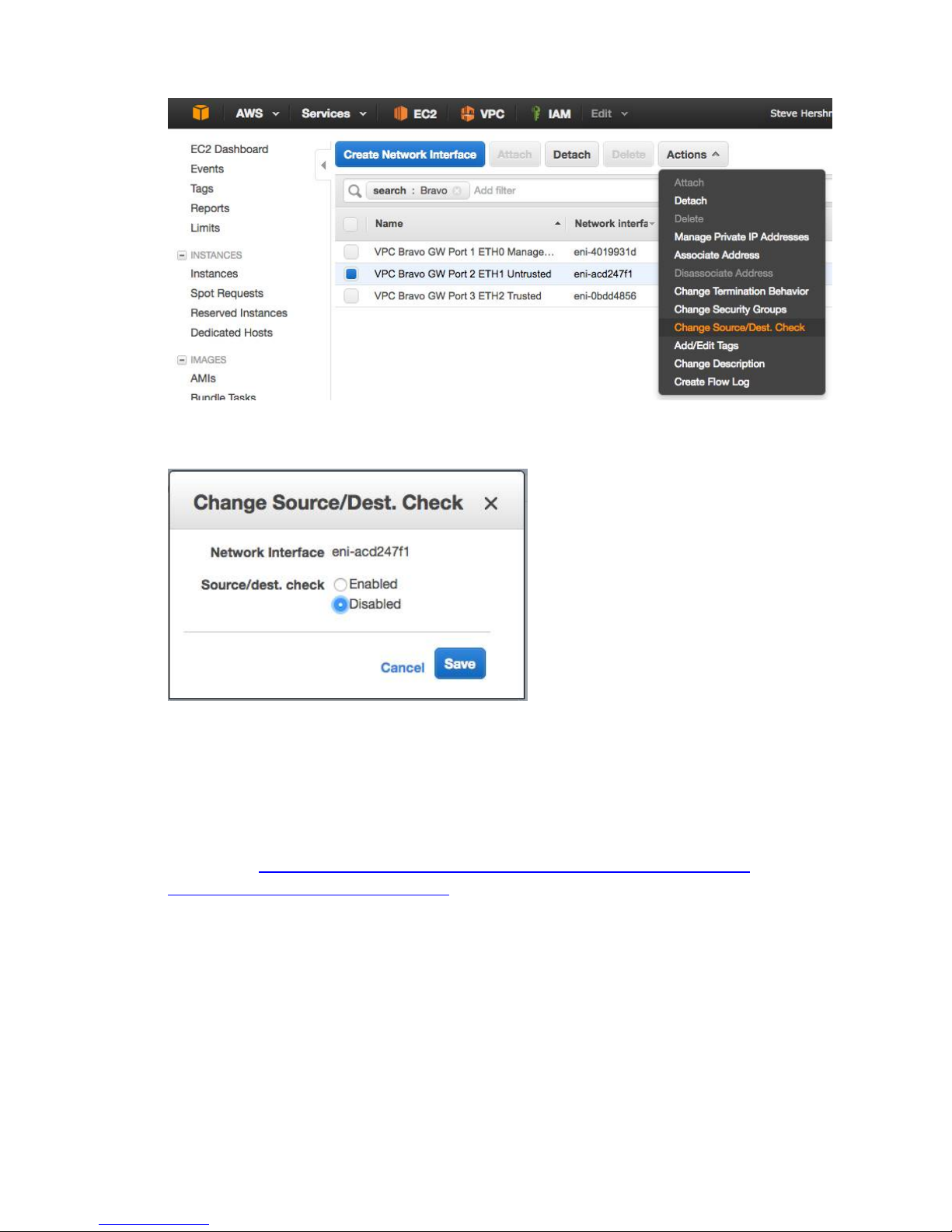
3. In the resulting popup, select Disabled, and click Save.
4. Repeat the last two steps for the Gateway’s Trusted interface.
Note: These settings are required to allow instances to handle traffic that isn’t
specifically intended for them (for example, instances providing NAT, routing or firewall
services).
Reference: https://docs.aws.amazon.com/AWSEC2/latest/UserGuide/using-
eni.html#change_source_dest_check
52
Page 54
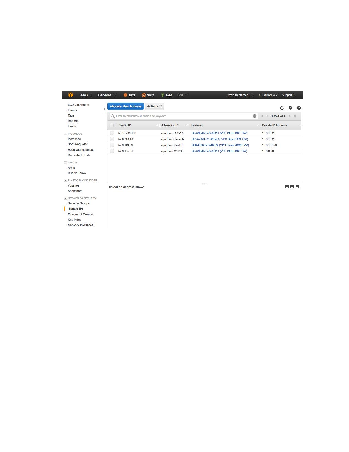
Task: Disable Source/Destination Check for Untrusted and
Trusted Interfaces
1. On the EC2 Dashboard, select Elastic IPs under Network & Security.
2. Click Allocate New Address.
3. Click Yes, Allocate.
53
Page 55
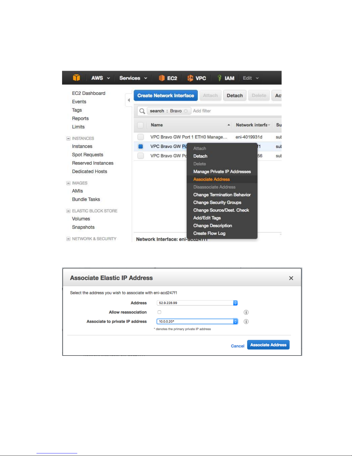
Task: Associate Elastic IP with the Public/Untrusted Interface
1. On the EC2 Dashboard, select Network Interfaces under Network & Security.
2. Select the Untrusted interface for the Gateway, right-click and select Associate Address.
3. Set the newly-created Elastic IP for the Address, and make sure the Gateway’s
Untrusted interface’s IP address populates the Associate to private IP address dropdown.
4. Click Associate Address.
54
Page 56

SECTION V
55
Page 57
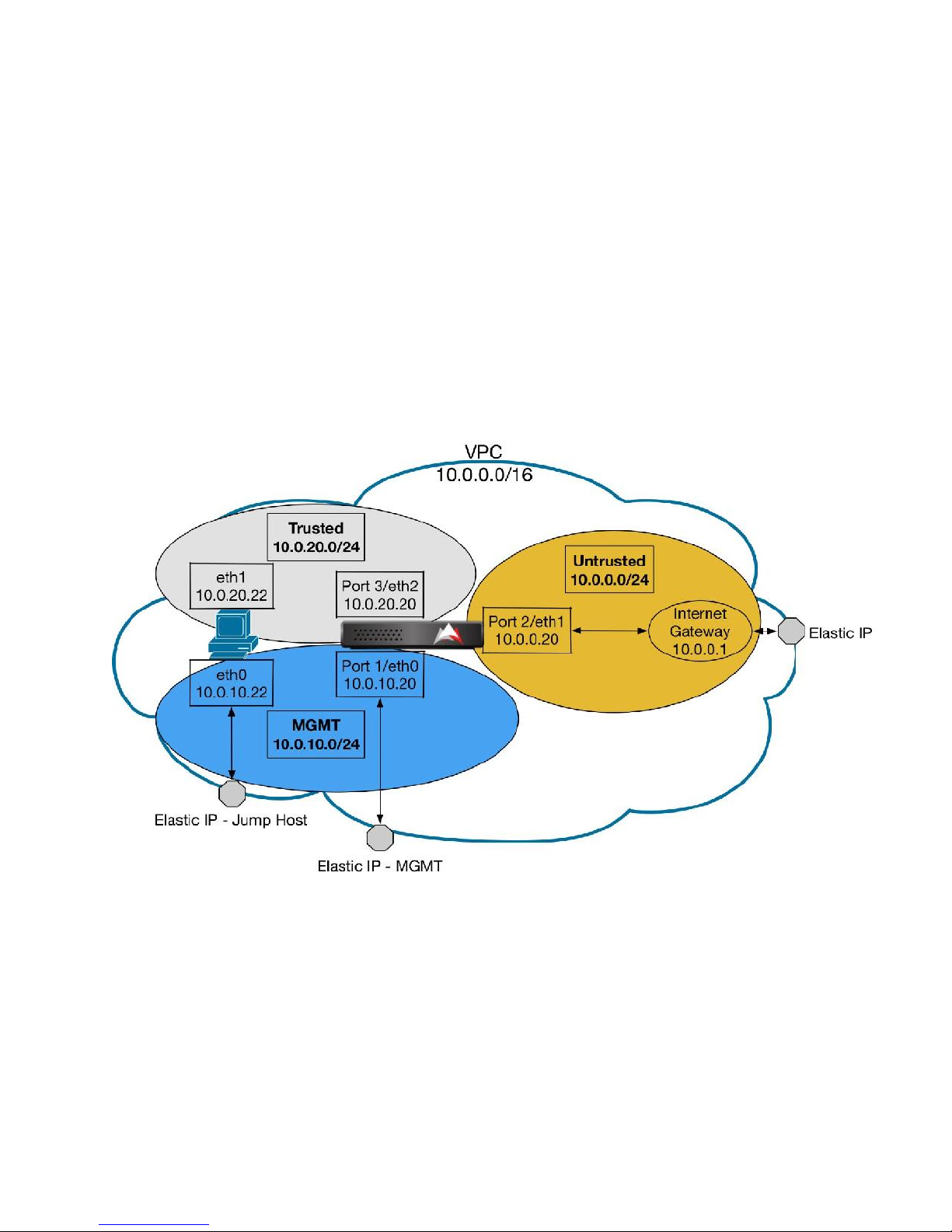
Deploy a Jump Host into the MGMT Subnet in VPC
This section describes how to create an Amazon instance that can be used as a jump host to
access the Trusted+Protected subnet behind the Gateway in AWS. As the Trusted + Protected
host will not be directly accessible from the internet, and no VPN or similar access is provided in
this setup, the jump host can be used to access the Trusted+Protected host as it will have two
NICs:
one on the MGMT subnet
one on the Trusted subnet
The jump host will have its MGMT interface mapped to an Elastic IP, making it accessible from
the internet.
56
Page 58
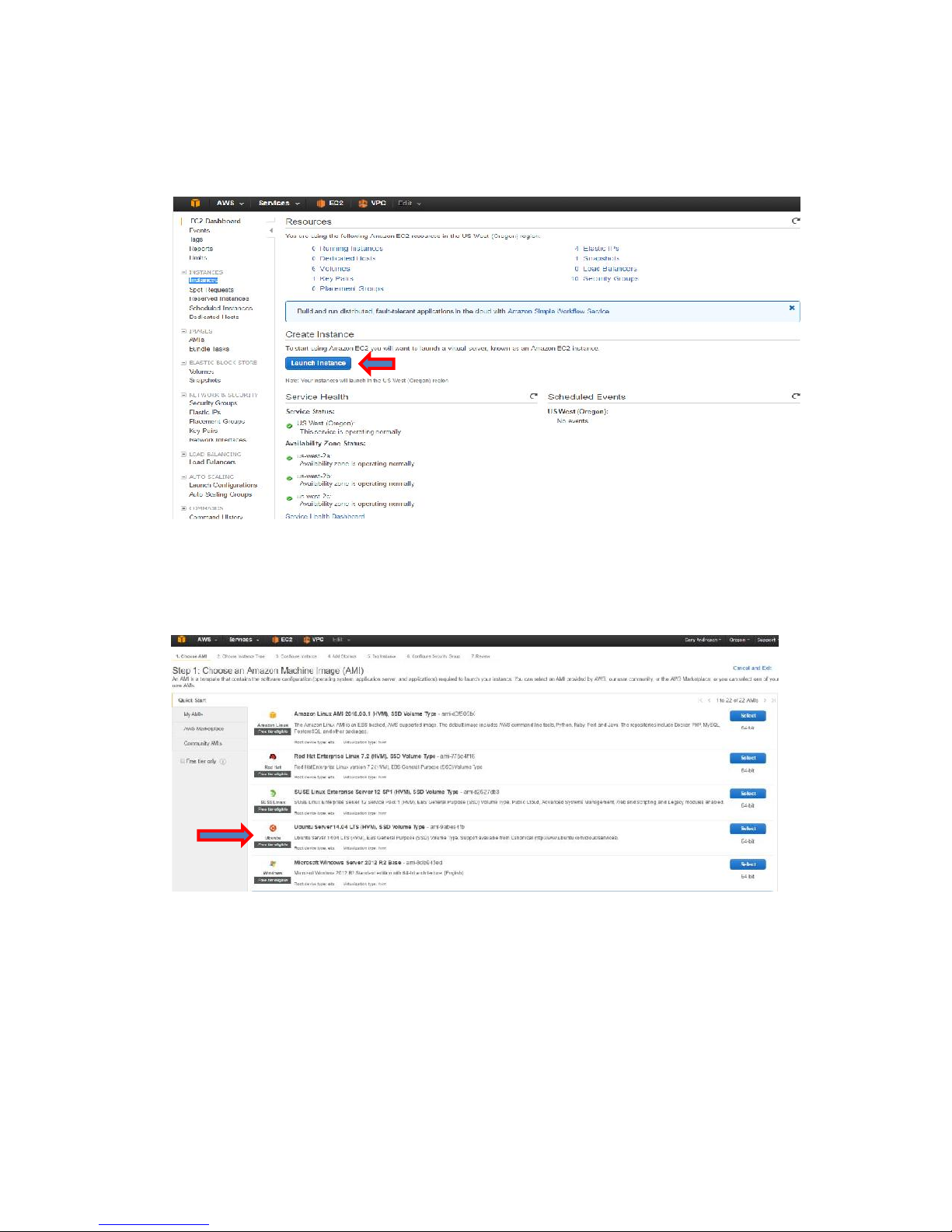
Task: Create the Jump Host Instance
1. From the EC2 Dashboard, click Launch Instance.
2. Select the AMI to use. This example uses the Ubuntu 14.04 LTS image (the Amazon Linux
image would also suffice).
57
Page 59
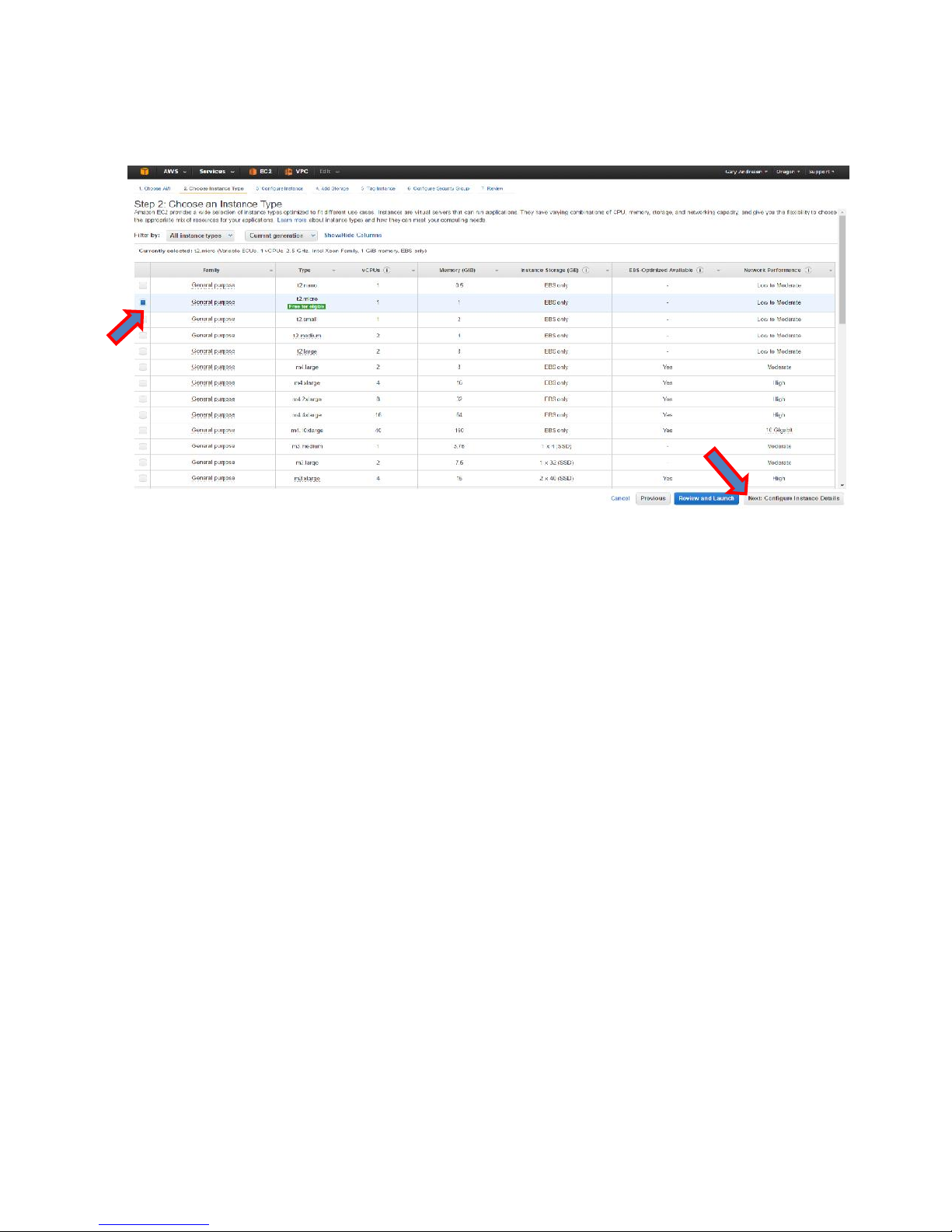
3. On the next screen (Step 2), select the t2.micro instance type, and click Next: Configure
Instance Details.
4. On the next page (Step 3), configure the following settings (using the defaults for those
not specified), and click Next: Add Storage.
a. Network - Your VPC.
b. Subnet - Select the MGMT subnet, which will map to eth0 on the instance.
c. Auto-assign Public IP – Disabled.
d. Network Interfaces section
i. eth0 > Primary IP - Select a free IP address in the MGMT subnet range
(for example, 10.0.10.22).
ii. Click Add Device under eth0.
iii. eth1 > Subnet - Select the Trusted subnet.
iv. eth1 > Primary IP - Select a free IP address in the Trusted subnet range (for example,
10.0.20.22).
58
Page 60
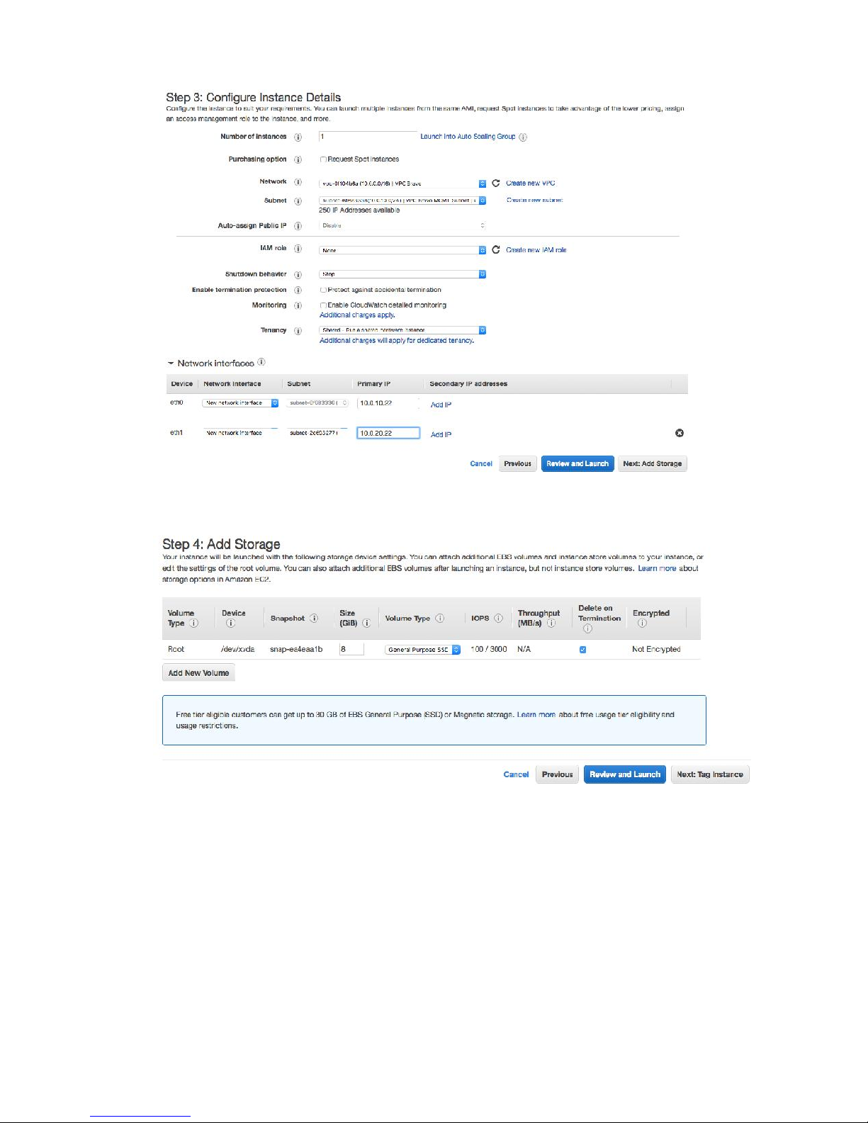
5. On the next page (Step 4), use the defaults and click Next: Tag Instance.
6. On the next page (Step 5), give the instance a name (for example, VPC Bravo MGMT
VM), and click Next: Configure Security Group.
59
Page 61
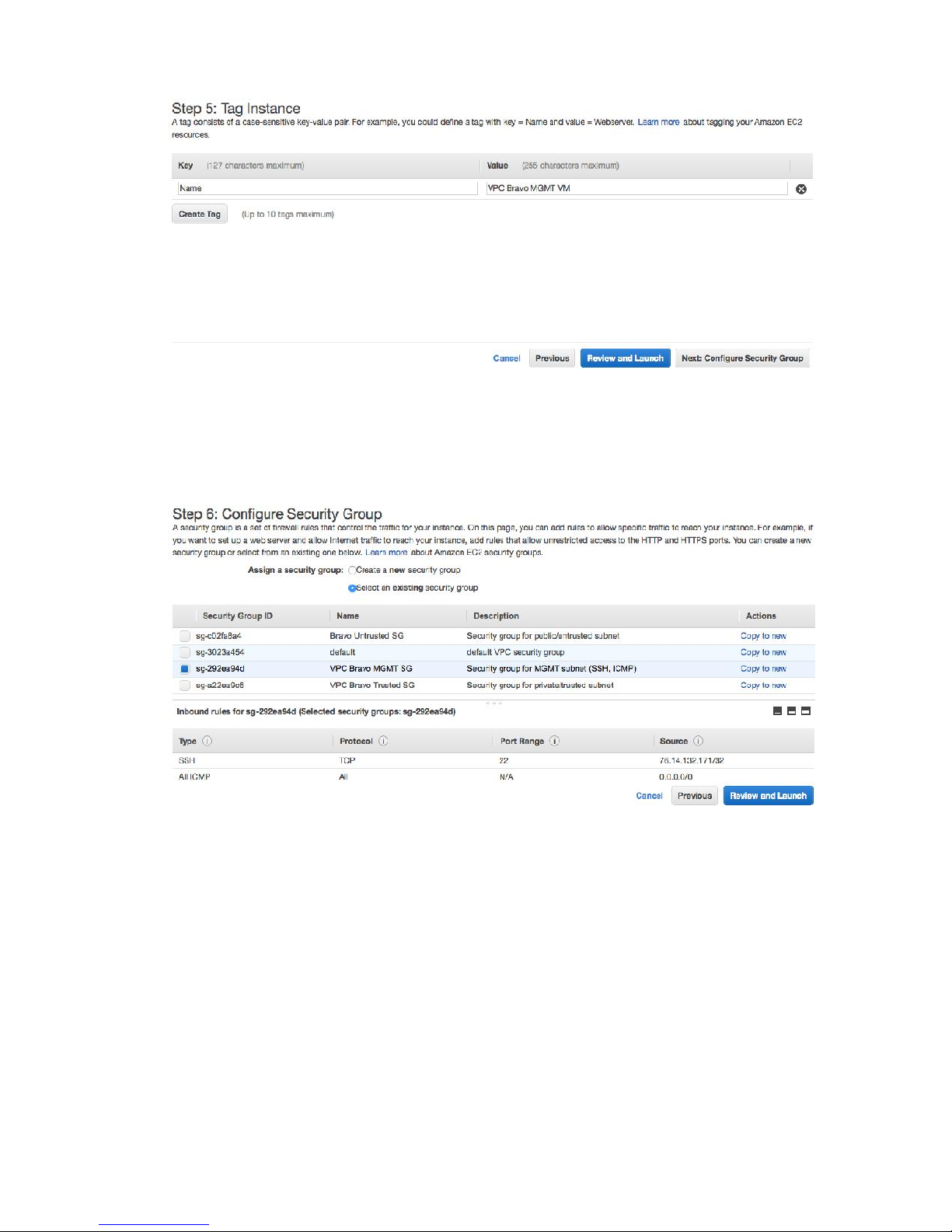
7. On the next page (Step 6), under Assign a security group:, choose Select an existing
security group.
8. In the result table, select your MGMT Security Group.
9. Click Review and Launch.
10. On the next page (Step 7), review the settings and click Launch.
60
Page 62
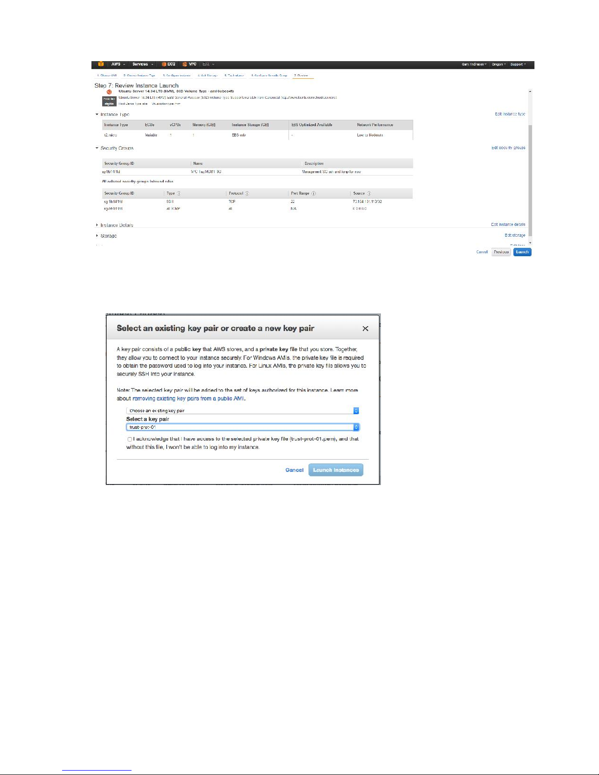
11. The Select an existing key pair or create a new key pair window appears.
a. If you already have a key pair that you’d like to use in AWS, select it from the
Select a key pair drop-down and click Launch Instances.
b. If you haven’t created a key pair yet, or would like to use a different/new key
pair, select Create a key pair from the drop down.
c. Input a name for the key pair, and click Download Key Pair to download the key
pair file to a save location.
d. Click Launch Instances.
61
Page 63
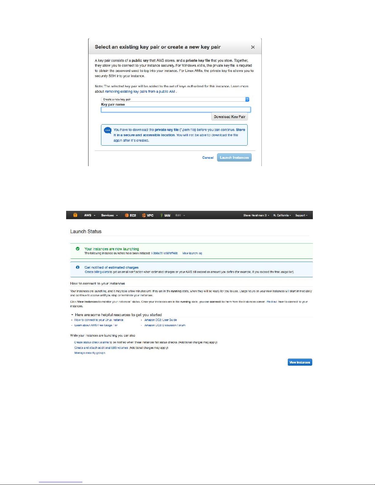
e. Either way, the key pair will be used to access the jump host over SSH in lieu of
password-based authentication.
12. On the resulting Launch Status page, click View Instances.
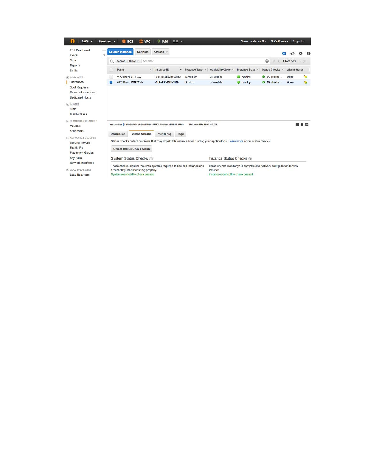
13. Locate your newly-created instance, and verify that the System Status Checks and
Instance Status Checks show green.
62
Page 64
63
Page 65
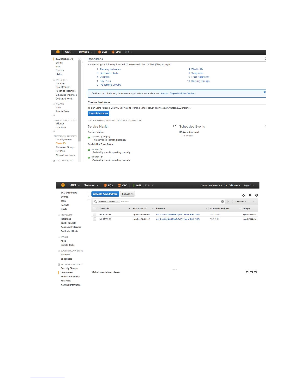
Task: Assign an Elastic IP to the Jump Host
1. Go to the EC2 Dashboard screen.
2. Under Network & Security in the left hand menu, select Elastic IPs.
3. Click Allocate New Address.
64
Page 66
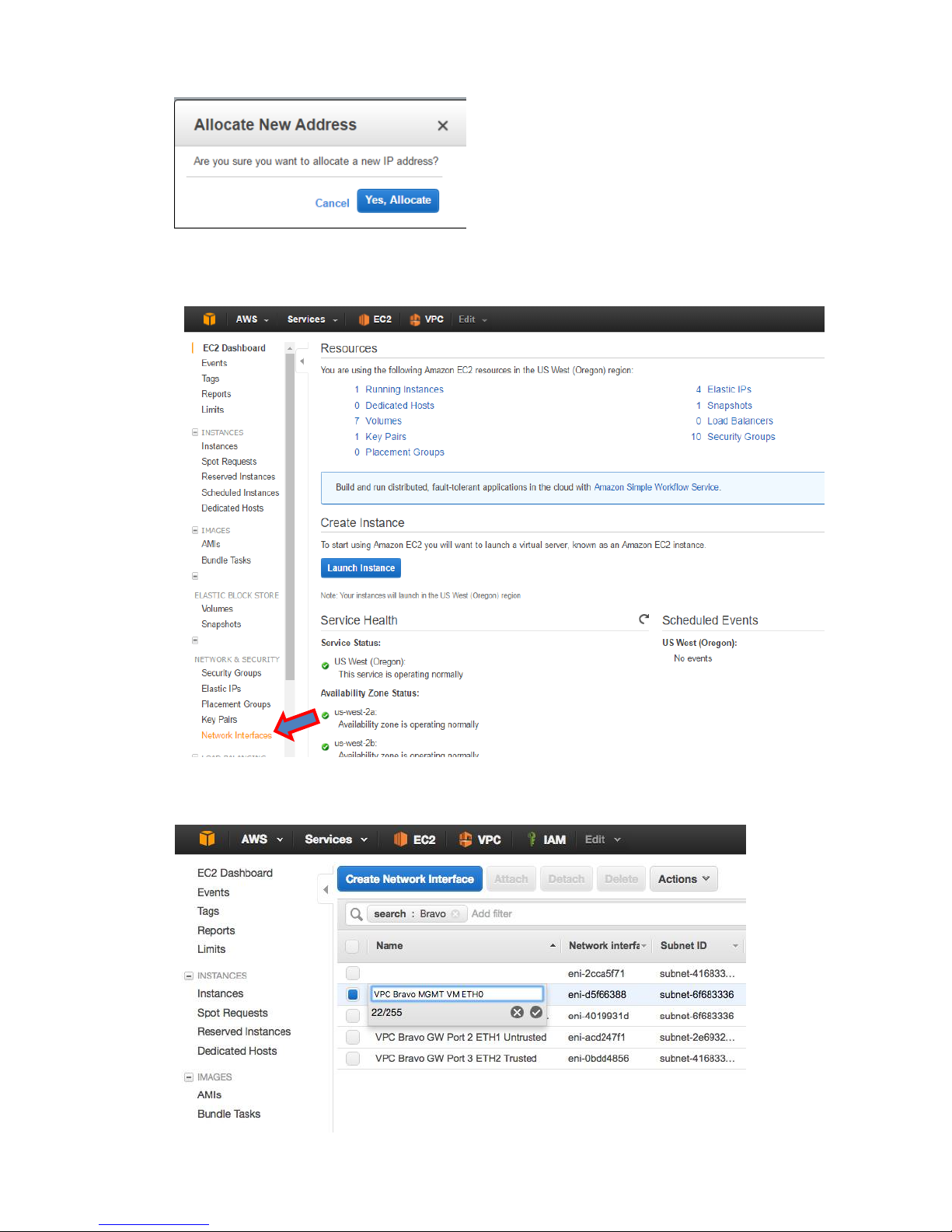
4. Click Yes, Allocate.
5. Under Network & Security in the left hand menu, click Network Interfaces.
65
Page 67
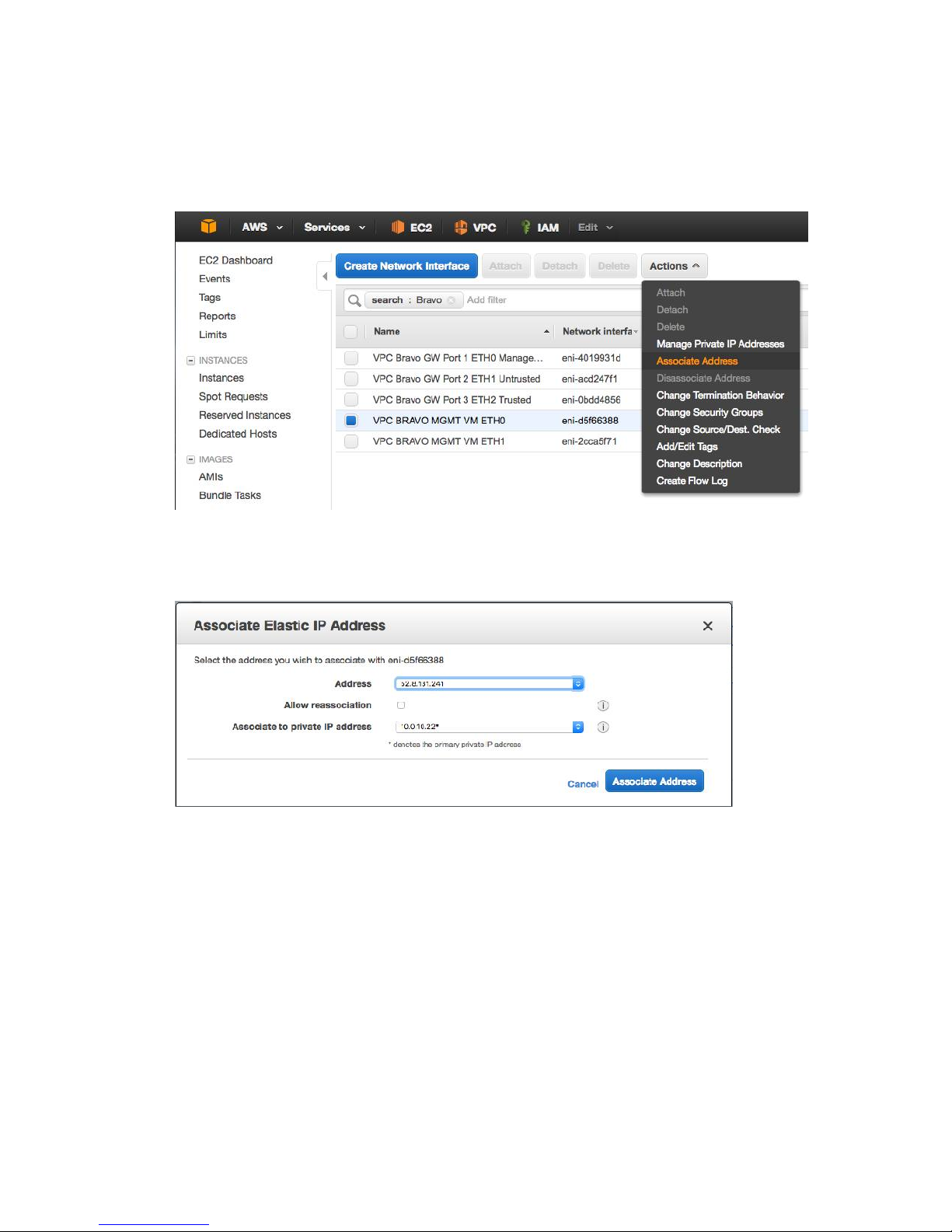
6. Locate the network interfaces for the jump host instance just created (using the
Primary IP values you set), and name them if blank. For example:
a. eth0 - VPC Bravo MGMT VM ETH0
b. eth1 - VPC Bravo MGMT VM ETH1
7. Select the eth0/MGMT interface for the instance, right-click and select Associate
Address from the popup menu.
8. In the resulting popup, select the just-created Elastic IP in the first dropdown, and
ensure the MGMT IP address is selected in the second dropdown. Click Associate
Address.
You should now be able to test connecting to the jump host over SSH.
66
Page 68
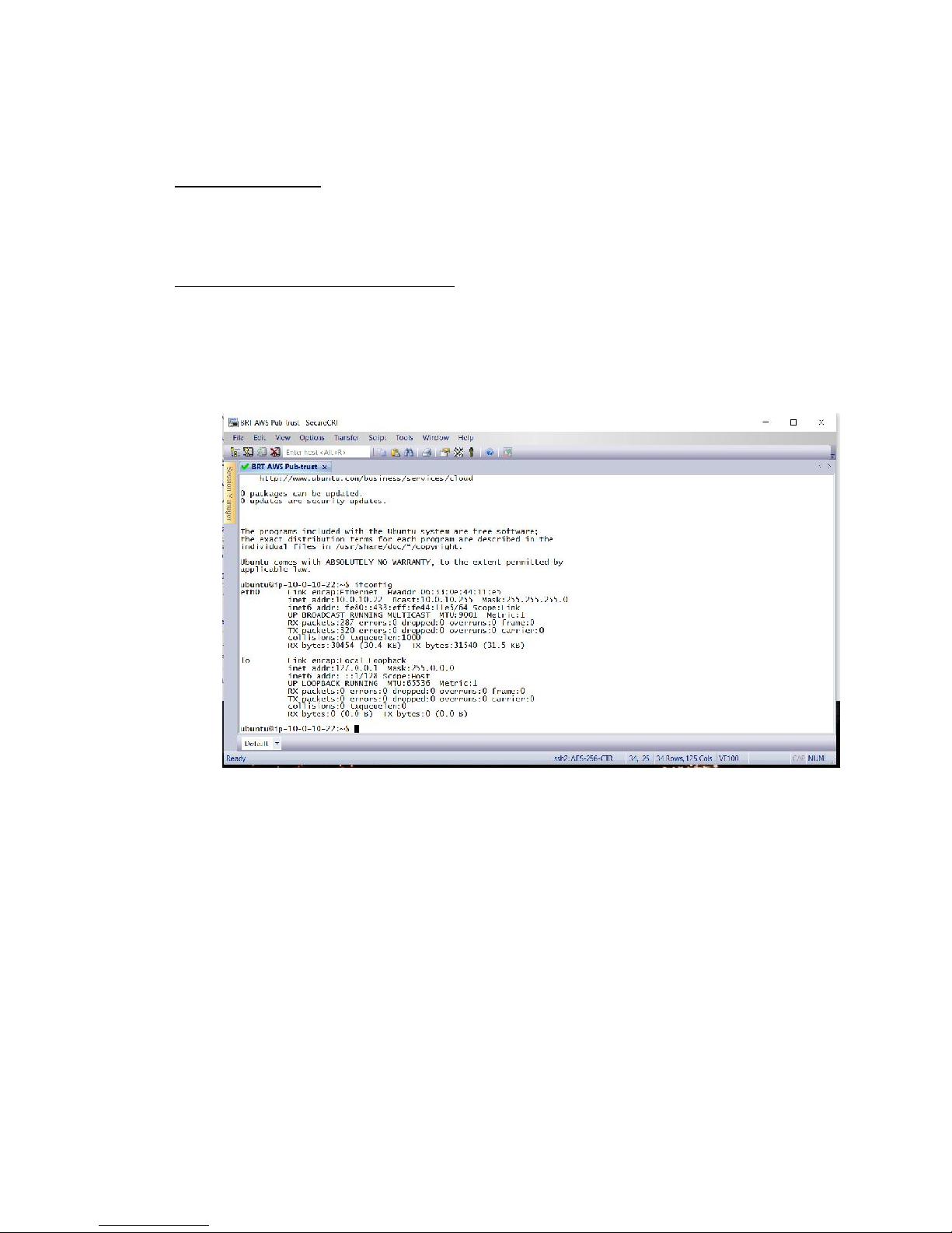
9. From the command line on Linux or Mac, use the following command to log in as the
ec2-user:
Ubuntu-based VMs
ssh -i /path/to/<key pair file>.pem ubuntu@<Elastic IP_MGMT>
ssh -i ~/.ssh/trust-prot-01.pem [email protected]
Red Hat or Amazon Linux-based VMs
ssh -i /path/to/<key pair file>.pem ec2-user@<Elastic IP_MGMT>
ssh -i ~/.ssh/trust-prot-01.pem [email protected]
a. On Windows, clients such as Putty or SecureCRT can be used.
67
Page 69

SECTION VI
68
Page 70
Deploy a (Trusted + Protected) Host into Trusted Subnet
in VPC
This section describes how to deploy a simple Linux-based Instance into the Trusted Subnet of
the VPC that can act as either a Trusted Host, or a Protected Resource, or both depending on
the network configuration. It includes steps on configuring custom routing rules to ensure that
traffic from the Instance is forced through the Gateway.
69
Page 71
Task: Provision an Instance of the Amazon Linux AMI
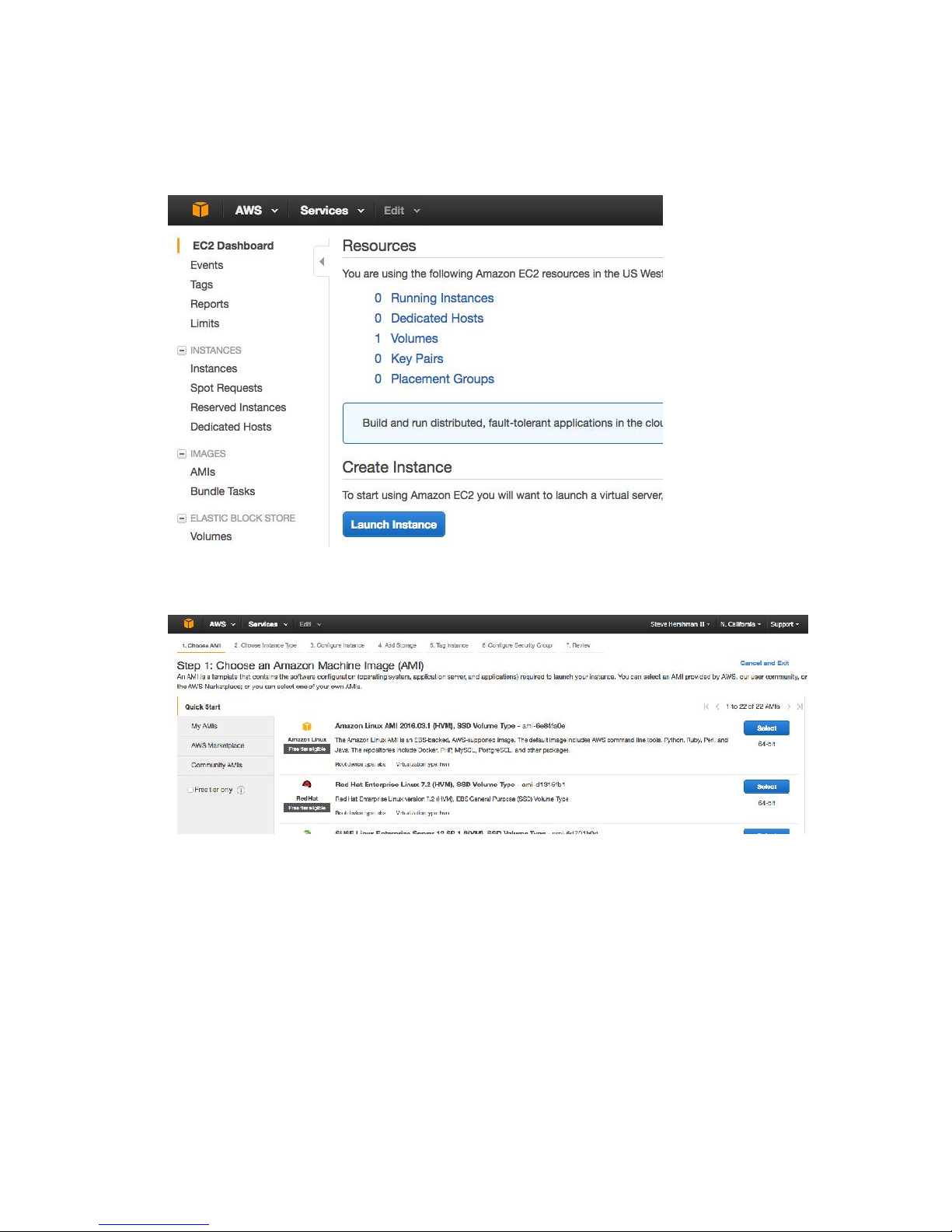
1. Using the web UI, click Services > EC2.
2. On the EC2 Dashboard, click Launch Instance.
3. On the next page (Step 1), select the Amazon Linux AMI image.
70
Page 72
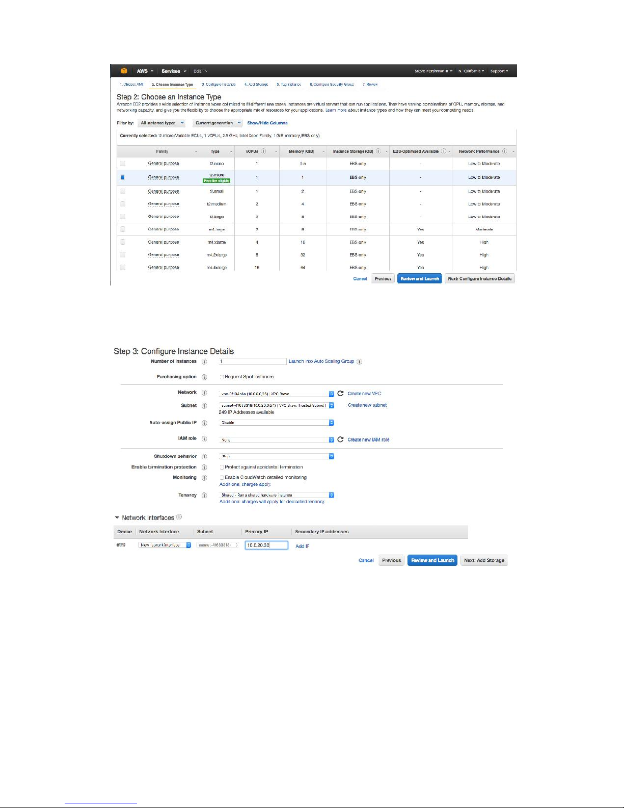
4. On the next page (Step 2), select the t2.micro image, then click on the “Next: Configure
Instance Details” button.
5. On the next page (Step 3), configure the following values.
a. Network – Type your VPC.
b. Subnet – Select the Trusted subnet.
c. Auto-assign Public IP – Select disable.
d. Network Interfaces > Primary IP – Assign an IP from the Trusted subnet, if
required. Otherwise, AWS will automatically assign a Primary IP.
6. Click Next: Add Storage.
7. On the next page (Step 4), accept the defaults, and click Next: Tag Instance.
71
Page 73
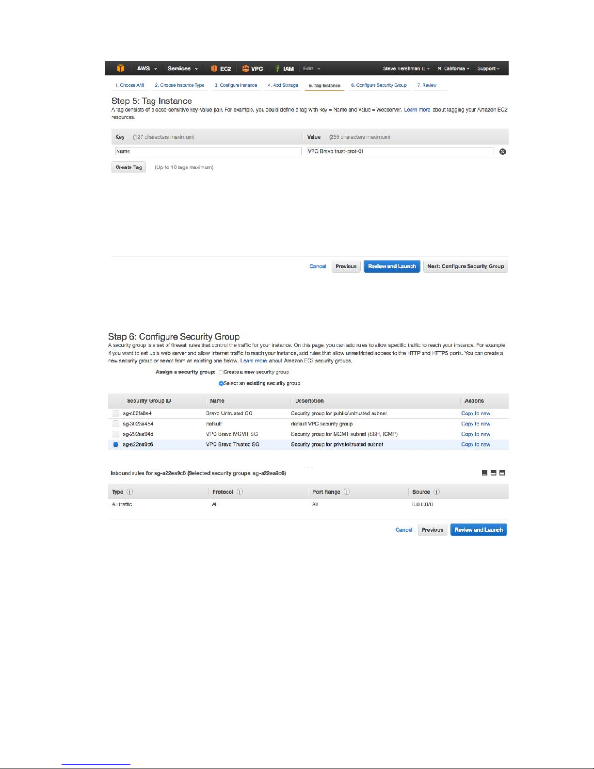
8. On the next page (Step 5), configure a Value for the Name tag (for example, VPC Bravo
trust-prot-01), and click Next: Configure Security Group.
9. On the next page (Step 6), under Assign a security group:, select Select an existing
security group.
10. Select the security group corresponding to the Trusted group, and click on Review and
Launch.
72
Page 74
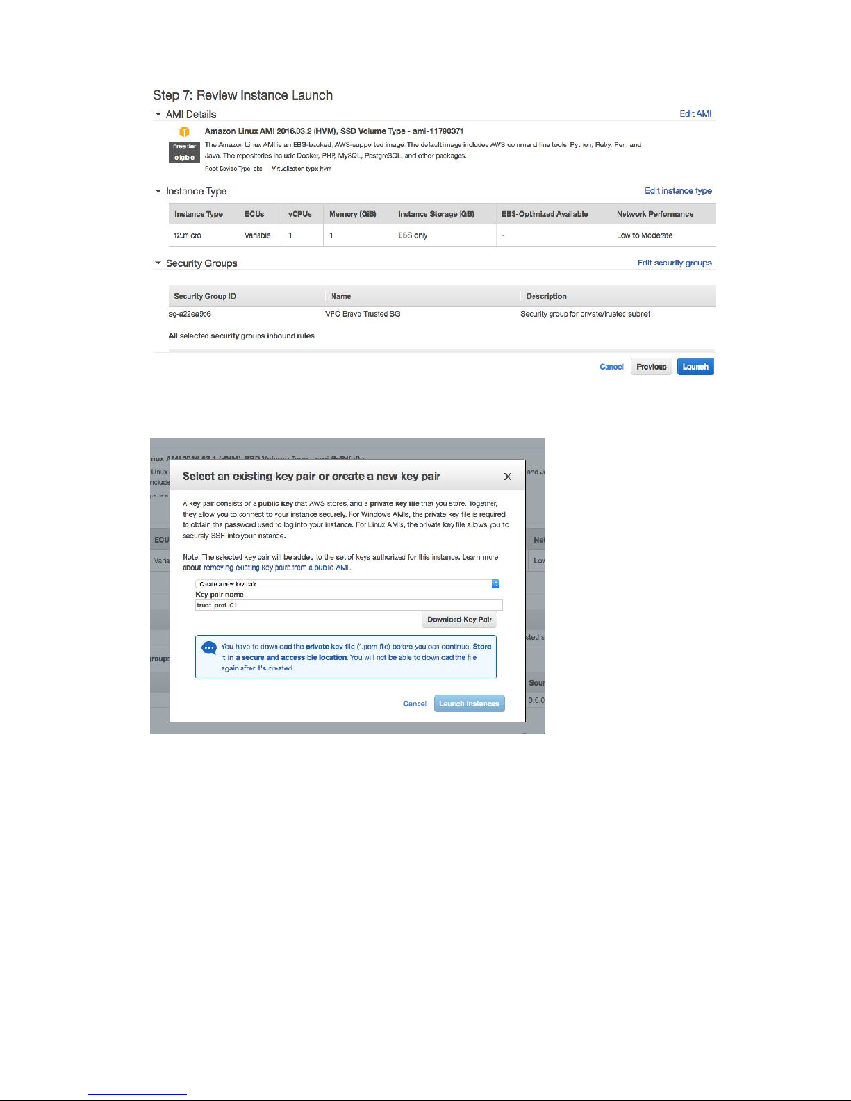
11. Review the details, and click Launch.
12. Select either Create a new key pair from the drop-down, and create a new key pair or
choose an existing key pair. If you create a new key pair, name it and click Download
Key Pair. Save this file to a secure and known location (for example, under ~/.ssh on
Mac or Linux). If lost you lose this information, you won’t be able to log into the VM
later, and you won’t be able to download the key pair again.
13. Click Launch Instances.
73
Page 75
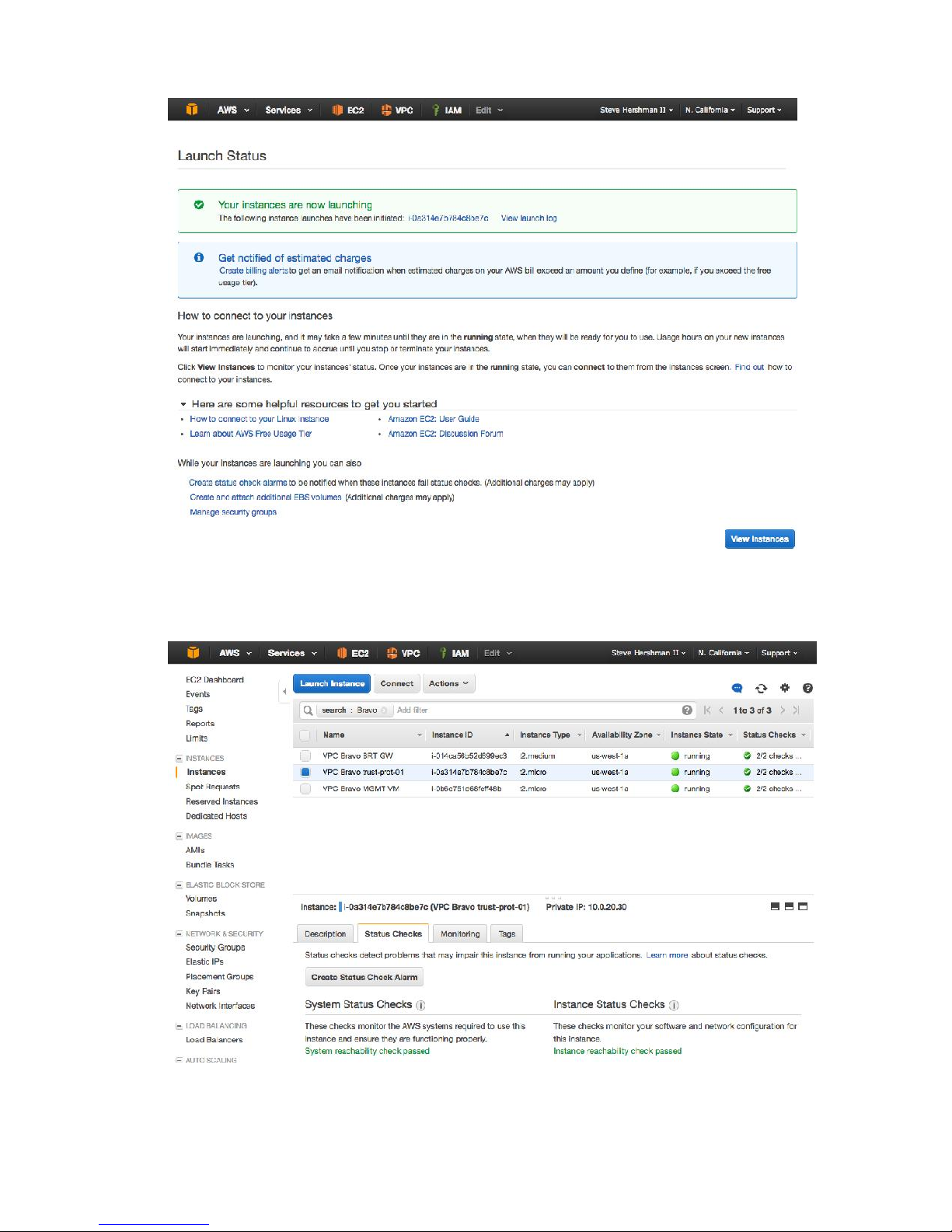
14. On the resulting Launch Status page, you should see a message indicating that the
instance is launching.
15. Click the instance ID in the message to navigate to the Instances screen on the EC2
Dashboard to verify the status of the VM.
74
Page 76
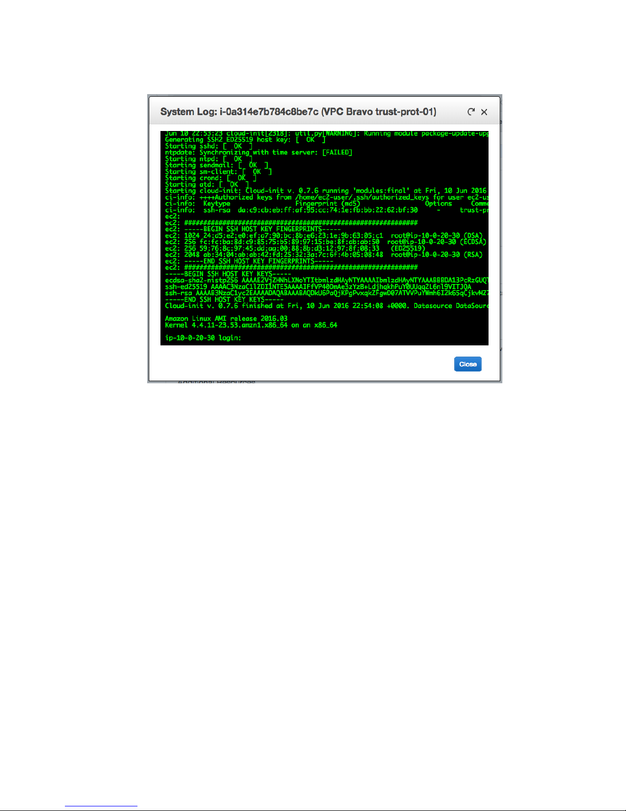
a. Open a Command window, type Actions > Instance Settings > Get System Log.
75
Page 77
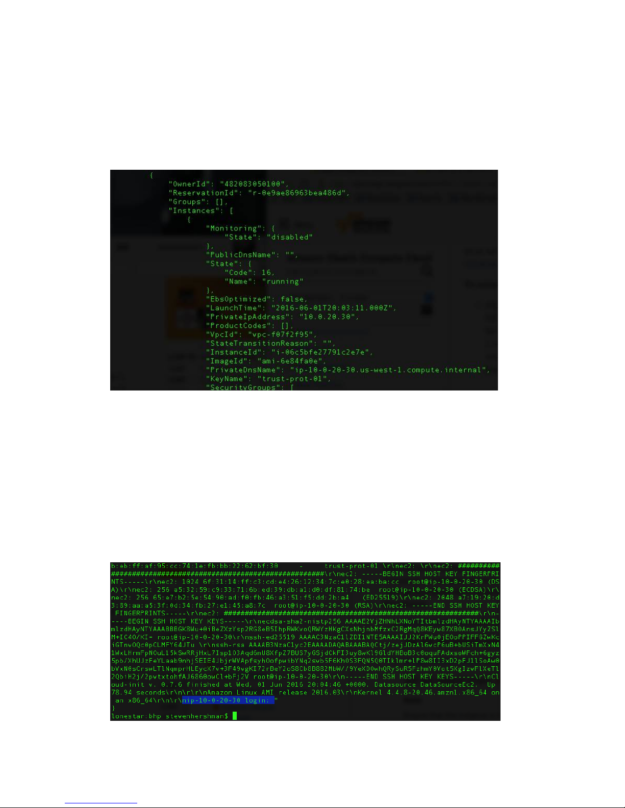
Task: Check Boot Status through AWS CLI
For details on configuring the AWS CLI on your system, please refer to Appendix A in the AWS
Deployment Guide.
1. From a terminal, run the following command: aws ec2 describe instances
2. Locate the entry for the just-deployed AMI, using the KeyName field (corresponds to the
Name Tag configured earlier).
3. Using that instance ID, run the following command:
aws ec2 get-console-output --instance-id <InstanceID>
4. The output should end with text for a login prompt. For example,:
nip-10-0-20-30 login: "
76
Page 78
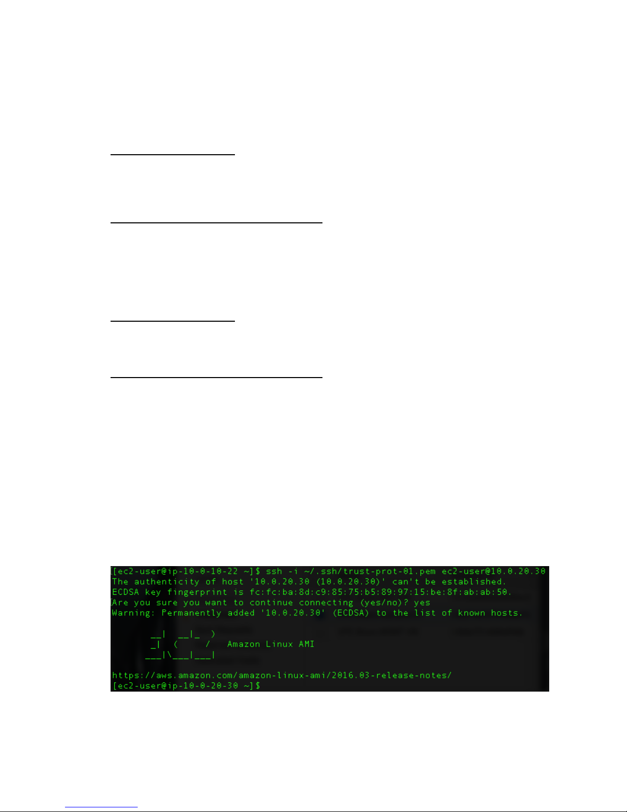
Task: SSH into Trusted + Protected Instance
1. Locate the key pair file associated with the Trusted+Protected instance, and scp it to the
jump host:
Ubuntu-based Instances:
scp -i ~/.ssh/trust-prot-01.pem ~/.ssh/trust-prot-01.pem
[email protected]:.ssh/.
Red Hat or Amazon Linux-based Instances:
scp -i ~/.ssh/trust-prot-01.pem ~/.ssh/trust-prot-01.pem ec2[email protected]:.ssh/.
2. Access the jump host using SSH:
Ubuntu-based Instances:
ssh -i ~/.ssh/trust-prot-01.pem [email protected]
Red Hat or Amazon Linux-based Instances:
ssh -i ~/.ssh/trust-prot-01.pem [email protected]
3. Change permissions on the key pair file so that only the current user can read it:
chmod 400 .ssh/trust-prot-01.pem
4. Now try to SSH to the Trusted+Protected machine, using its internal IP address on the
Trusted subnet. Reference the key pair file in the command as shown below to
authenticate and log into the machine. For example:
ssh -i ~/.ssh/trust-prot-01.pem [email protected]
77
Page 79
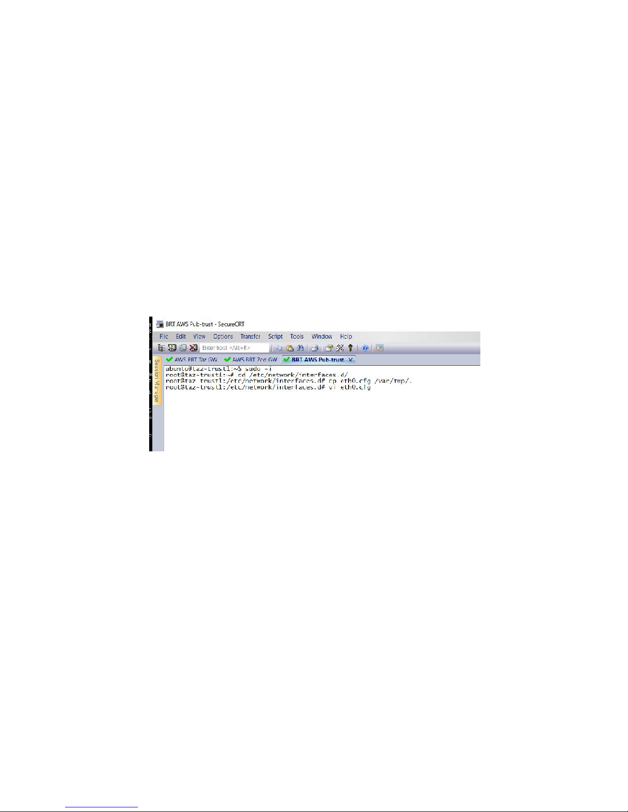
Task: Configure Static Networking and Routes on the Trusted +
Protected Instance
In order to ensure that traffic to and from the Trusted + Protected instance is routed through
the Gateway, the networking will be re-configured on that instance from DHCP-based to static.
At the same time, the default gateway will be redirected to use the BRT TAC Gateway Trusted
Interface (10.0.20.20) instead of the default gateway assigned by AWS (10.0.20.1).
1. For Ubuntu-based instances:
a. Run the command: sudo -i
b. Type: cd /etc/network/interfaces.d
c. Make a copy of: eth0.cfg ‘cp eth0.cfg /var/tmp.’.
d. Log into your trusted/protect host through the MGMT node.
e. Again, run the command su -i or run all commands as: sudo xxxcomand
f. Type: cd /etc/network/interfaces.d
g. Make a copy of: eth0.cfg ‘cp eth0.cfg /var/tmp.’.
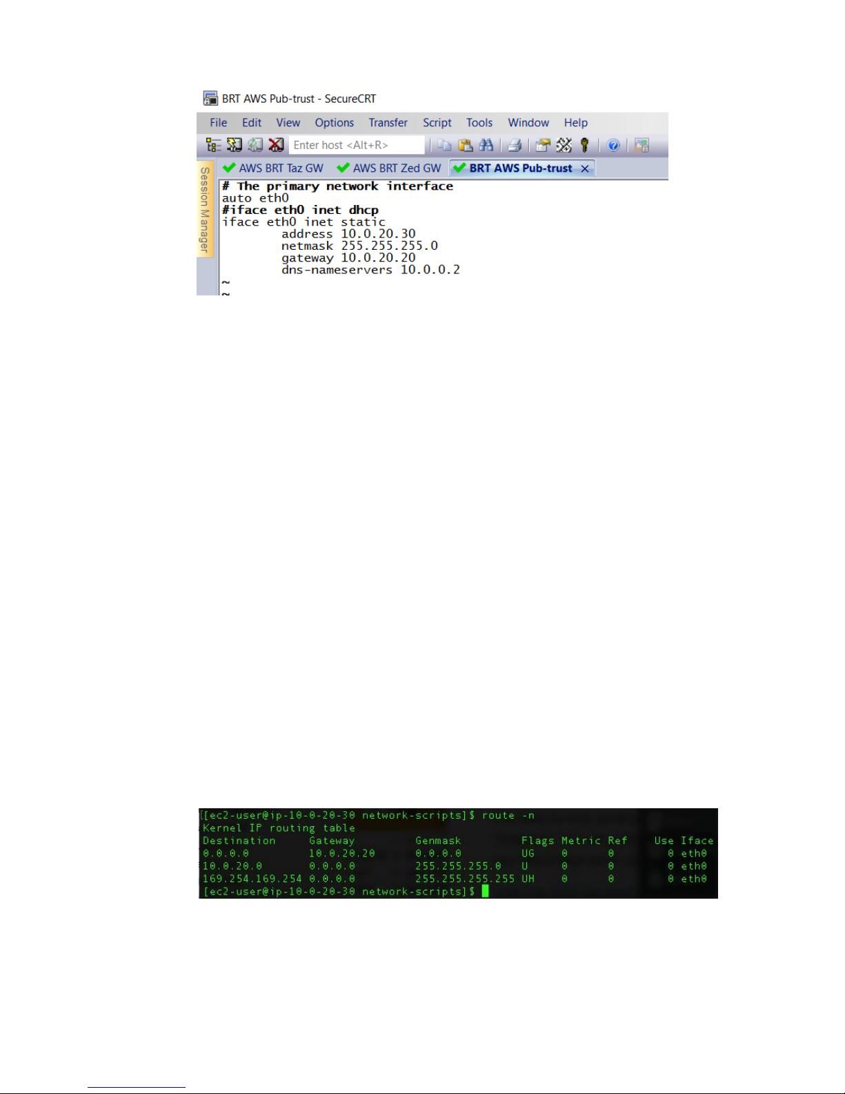
h. Edit eth0.cfg and change the following:
# The primary network interface
auto eth0
iface eth0 inet dhcp
To this:
# The primary network interface
auto eth0
#iface eth0 inet dhcp
iface eth0 inet static
address 10.0.20.30
netmask 255.255.255.0
gateway 10.0.20.20
dns-nameservers 10.0.0.2
Note: AWS uses a *.2 address for DNS.
78
Page 80
i. Type ifdown eth0; ifup eth0 to restart the interface.
j. Type ping 10.0.0.1 to test that the networking is configured correctly (which
would not work previously)
2. For Red Hat/Amazon Linux-based instances:
a. Type: cd /etc/sysconfig/network-scripts/
b. Replace the contents of the ifcfg-eth0 file with the following:
DEVICE=eth0
BOOTPROTO=none
ONBOOT=yes
TYPE=Ethernet
USERCTL=yes
PEERDNS=yes
IPV6INIT=no
#PERSISTENT_DHCLIENT=yes
RES_OPTIONS="timeout:2 attempts:5"
#DHCP_ARP_CHECK=no
IPADDR=10.0.20.30
NETMASK=255.255.255.0
GATEWAY=10.0.20.20
DNS1=10.0.0.2
c. Run the command: /etc/init.d/network restart
d. Run route -n to verify that routing is correct.
79
Page 81

SECTION VII
80
Page 82
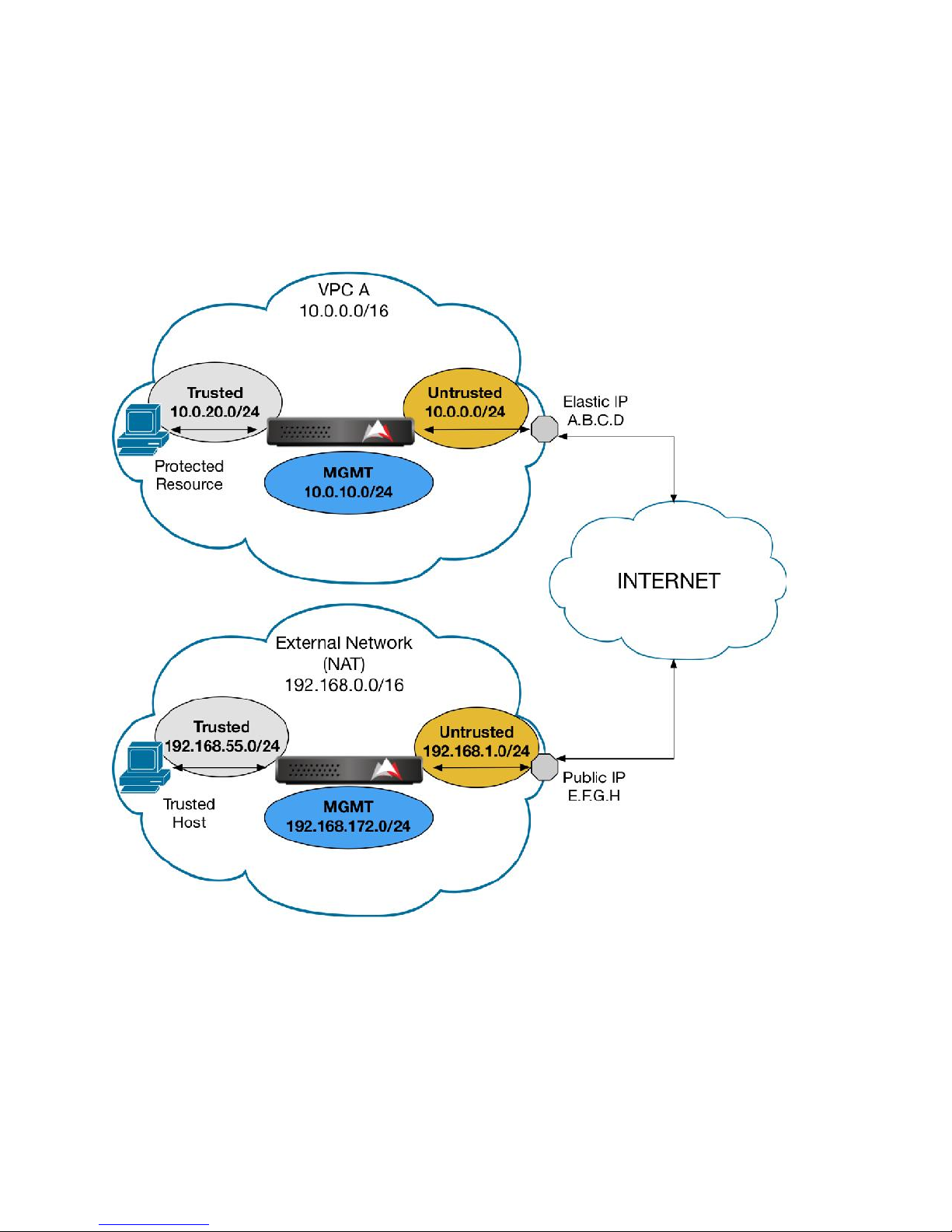
Configure Layer 3 NAT – External-to-VPC (Unidirectional)
This section describes how to connect an Insertion Gateway in an external network (behind a
NAT firewall) to a Resolving Gateway in a VPC.
81
Page 83
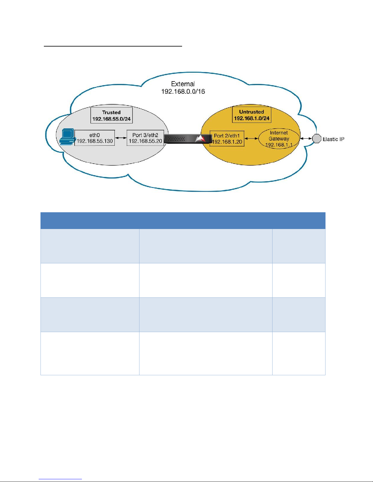
Variable
Description
Value
INS_TRUST_HOST_IP
IP address of the Trusted Host in the
Trusted Subnet; Trusted side of NAT
config
192.168.55.130
INS_TRUST_GW_IP
IP address of the Gateway Interface in the
Trusted Subnet; Trusted side of Route
config
192.168.55.20
INS_UNTRUST_GW_IP
IP address of the Gateway Interface in the
Untrusted Subnet; Untrusted side of NAT
config
192.168.1.20
INS_UNTRUST_ROUTER_IP
IP address of the Router Interface in the
Untrusted Subnet used to send traffic out
of the network; Untrusted side of Route
config
192.168.1.1
External Network Configuration (Trusted Host)
82
Page 84
83
Page 85
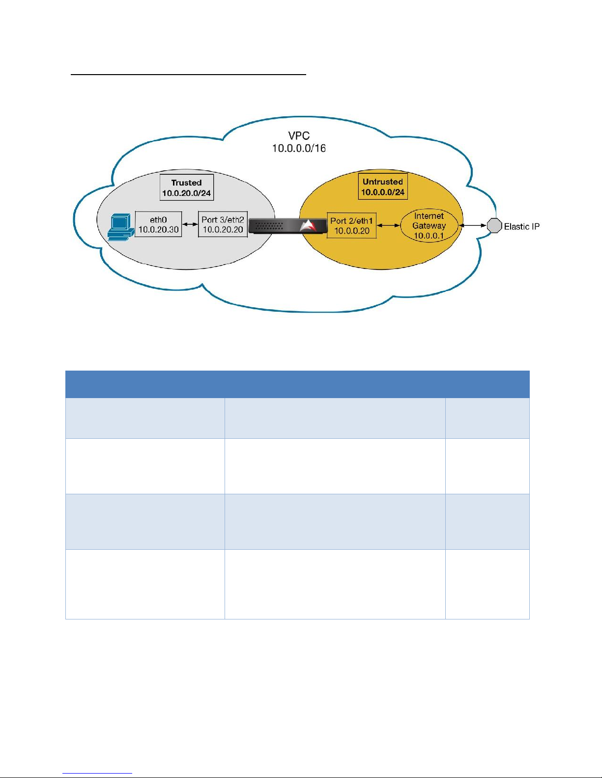
Variable
Description
Value
RES_TRUST_HOST_IP
IP address of the Trusted Host in the
Trusted Subnet; Trusted side of NAT config
10.0.20.30
RES_TRUST_GW_IP
IP address of the Gateway Interface in the
Trusted Subnet; Trusted side of Route
config
10.0.20.20
RES_UNTRUST_GW_IP
IP address of the Gateway Interface in the
Untrusted Subnet; Untrusted side of NAT
config
10.0.0.20
RES_UNTRUST_ROUTER_IP
IP address of the Router Interface in the
Untrusted Subnet used to send traffic out
of the network; Untrusted side of Route
config
10.0.0.1
VPC Network Configuration (Protected Resource)
84
Page 86
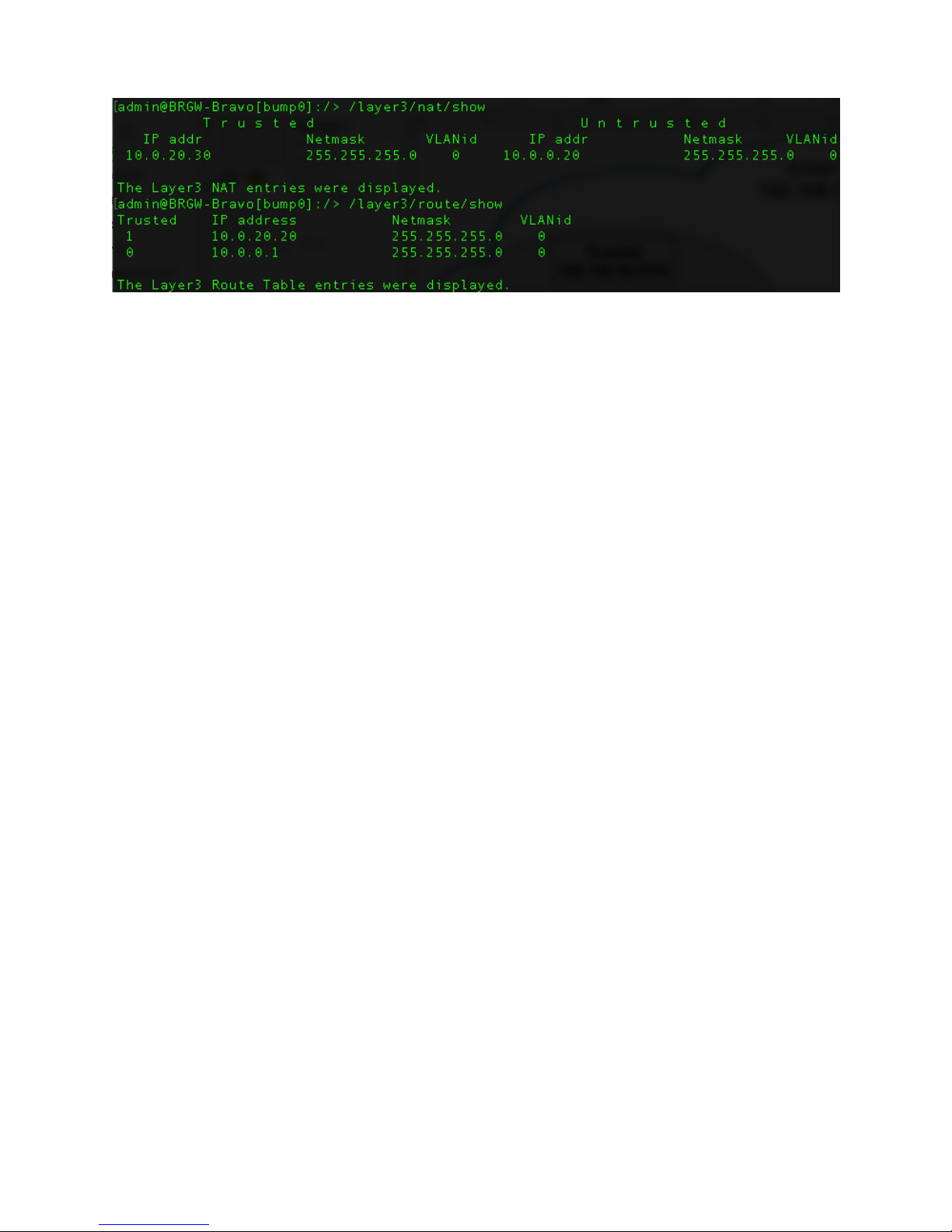
85
Page 87
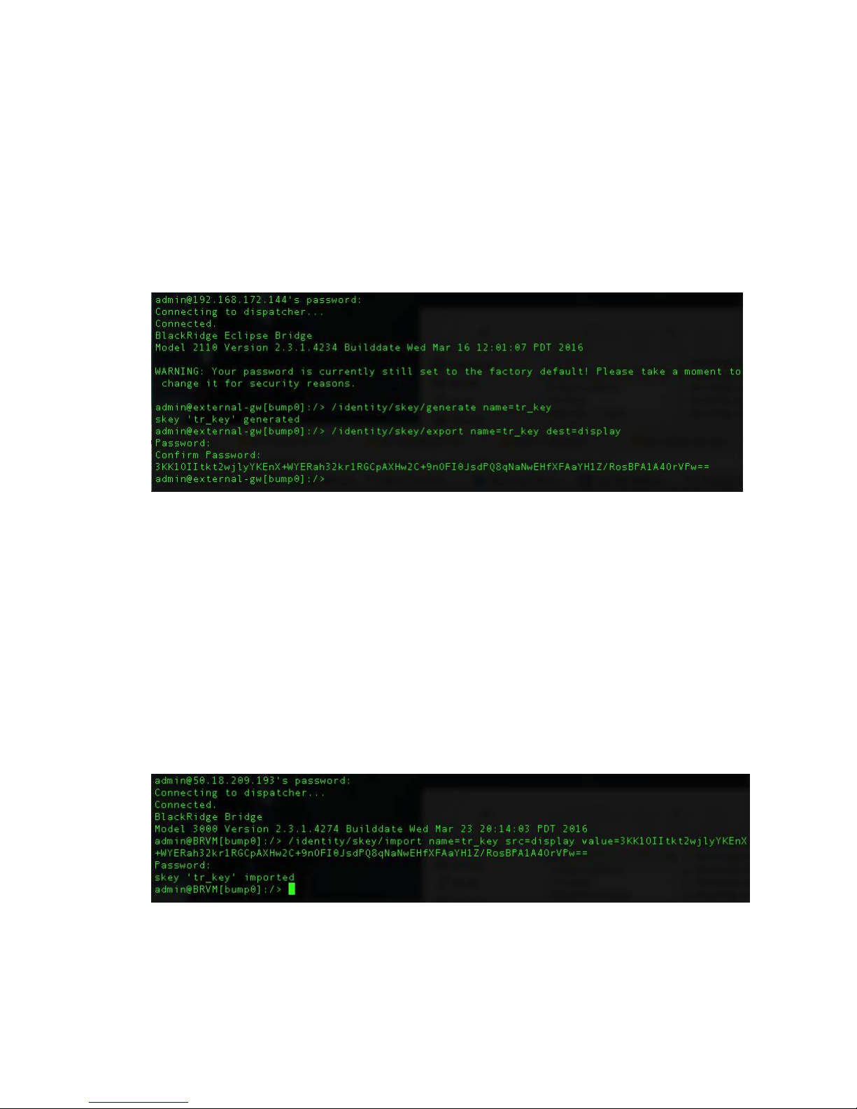
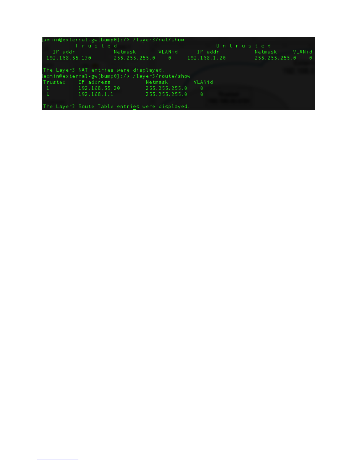
Task: Inserter – Generate and Export SKEY
1. SSH into the MGMT interface of the Inserter Gateway as “admin”.
2. Run the following commands:
/identity/skey/generate name=tr_key
/identity/skey/export name=tr_key dest=display
3. When prompted, input a password of your choosing twice to encrypt the skey value.
4. Copy the value printed to screen for use in the next step.
Task: Resolver – Import SKEY
1. SSH into the MGMT interface of the Resolver Gateway as “admin”.
2. Run the following command, using the skey value and password from the previous step:
/identity/skey/import name=tr_key src=display
value=<displayed key value from above>
Task: Inserter – Add NAT and Routes
1. On the Inserter Gateway, run the following commands:
86
Page 88
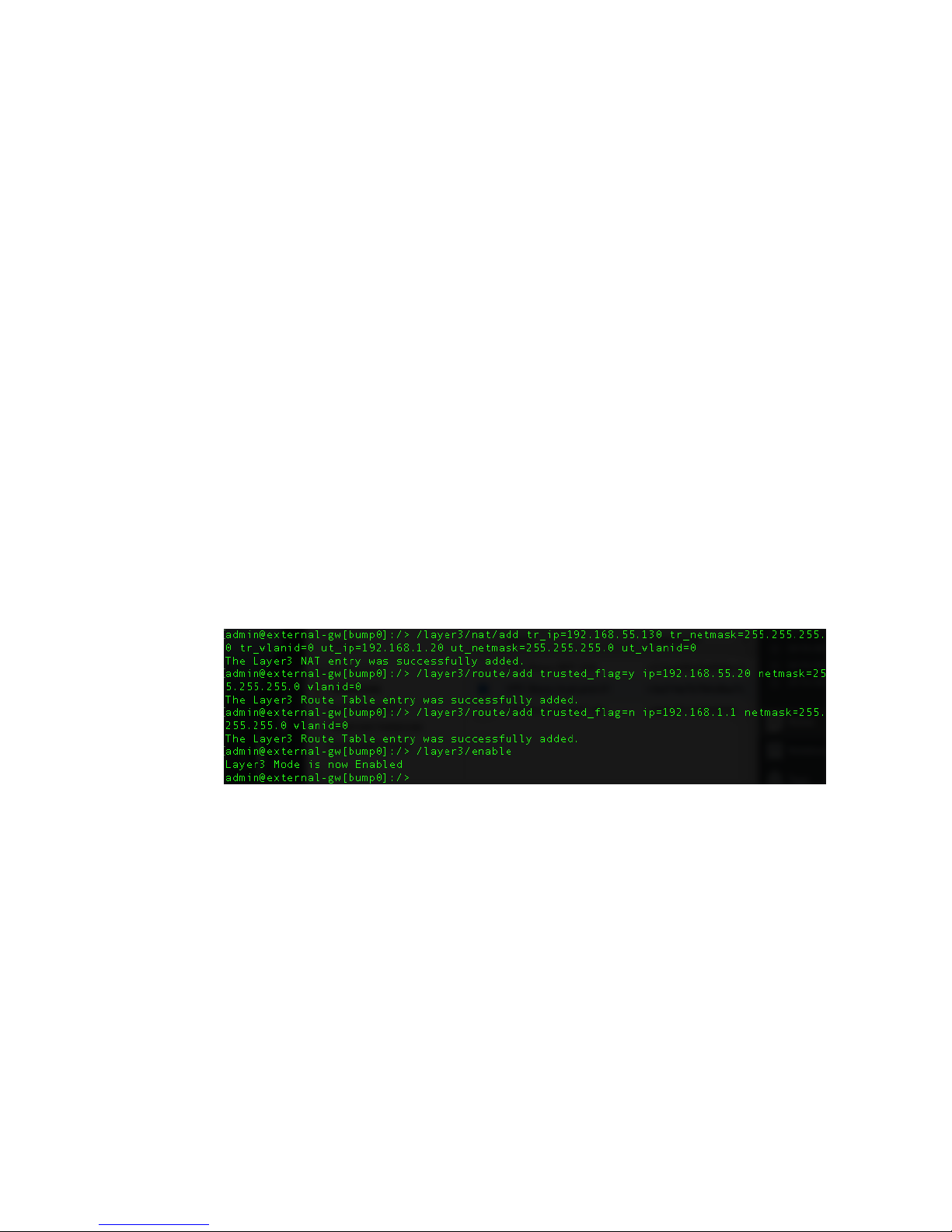
a. /layer3/nat/add tr_ip=<INS_TRUST_HOST_IP>
tr_netmask=255.255.255.0 tr_vlanid=0
ut_ip=<INS_UNTRUST_GW_IP> ut_netmask=255.255.255.0
ut_vlanid=0
i. INS_TRUST_HOST_IP = IP of the Trusted Host in the Trusted Subnet
ii. INS_UNTRUST_GW_IP = IP of the Gateway interface in the Untrusted
Subnet
b. /layer3/route/add trusted_flag=y ip=<INS_TRUST_GW_IP>
netmask=255.255.255.0 vlanid=0
i. INS_TRUST_GW_IP = IP of the Gateway interface in the Trusted
Subnet
c. /layer3/route/add trusted_flag=n
ip=<INS_UNTRUST_ROUTER_IP> netmask=255.255.255.0
vlanid=0
i. INS_UNTRUST_ROUTER_IP = IP of the Router interface in the
Untrusted Subnet
d. /layer3/enable
Task: Inserter – Add NAT and Routes
1. On the Resolving Gateway, run the following commands:
a. /layer3/nat/add tr_ip=<RES_TRUST_HOST_IP>
tr_netmask=255.255.255.0 tr_vlanid=0
ut_ip=<RES_UNTRUST_GW_IP> ut_netmask=255.255.255.0
ut_vlanid=0
i. RES_TRUST_HOST_IP = IP of the Trusted Host in the Trusted Subnet
ii. RES_UNTRUST_GW_IP = IP of the Gateway interface in the Untrusted
Subnet
87
Page 89
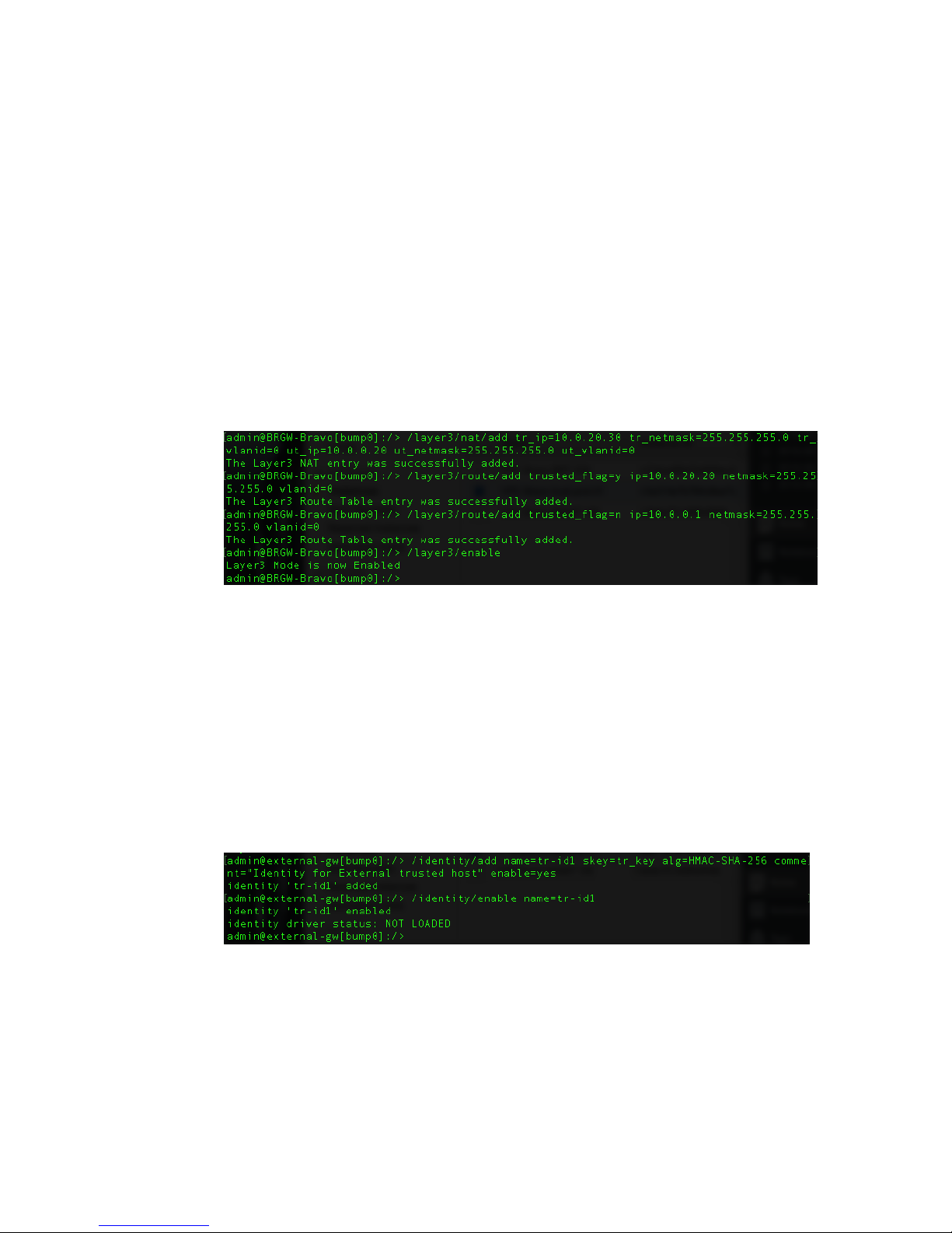
b. /layer3/route/add trusted_flag=y ip=<RES_TRUST_GW_IP>
netmask=255.255.255.0 vlanid=0
i. RES_TRUST_GW_IP = IP of the Gateway interface in the Trusted
Subnet
c. /layer3/route/add trusted_flag=n
ip=<RES_UNTRUST_ROUTER_IP> netmask=255.255.255.0
vlanid=0
i. RES_UNTRUST_ROUTER_IP = IP of the Router interface in the
Untrusted Subnet
d. /layer3/enable
Task: Inserter – Add and Enable Identity
1. On the Inserter Gateway, create an Identity and enable it:
a. /identity/add name=tr-id1 skey=tr_key alg=HMAC-SHA-256
comment="Identity for External trusted host"
enable=yes
b. /identity/enable name=tr-id1
Task: Inserter – Create Trusted Host and Associate
Identity
1. On the Inserter side, create a Trusted Host and associate it with the Identity:
88
Page 90
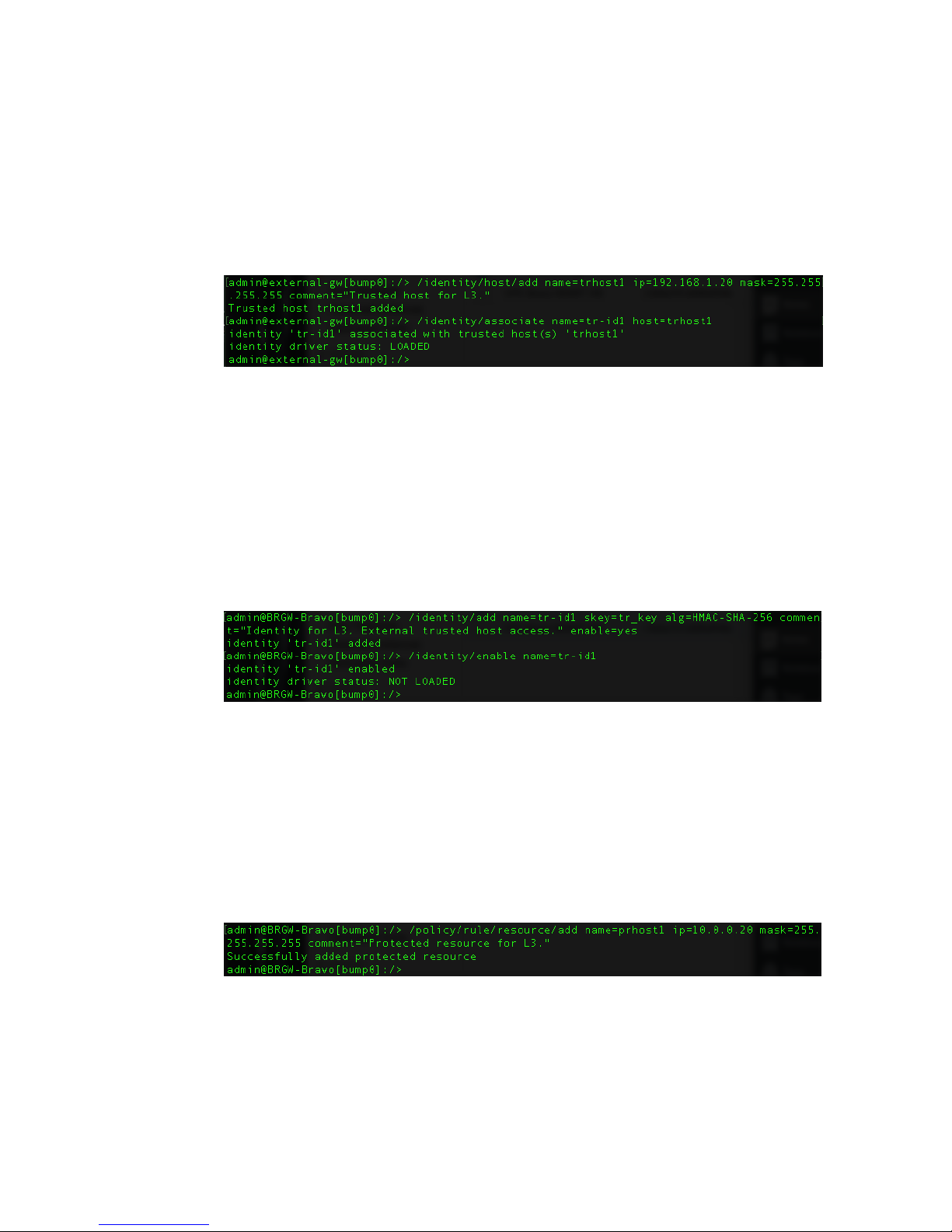
a. /identity/host/add name=trhost1 ip=<INS_UNTRUST_GW_IP>
mask=255.255.255.255 comment="Trusted host for L3."
i. INS_UNTRUST_GW_IP = IP of the Gateway interface in the
Untrusted Subnet
b. /identity/associate name=tr-id1 host=trhost1
Task: Resolver – Add and Enable Identity Using SKEY
1. On the Resolver side, create and enable a corresponding identity:
a. /identity/add name=tr-id1 skey=tr_key alg=HMAC-SHA-256
comment="Identity for L3, External trusted host
access." enable=yes
b. /identity/enable name=tr-id1
Task: Resolver – Add Protected Resource
1. On the Resolver side, configure the Protected Resource:
a. /policy/rule/resource/add name=prhost1
ip=<RES_UNTRUST_GW_IP> mask=255.255.255.255
comment="Protected resource for L3."
i. RES_UNTRUST_GW_IP = IP of the Gateway interface in the
Untrusted Subnet
89
Page 91
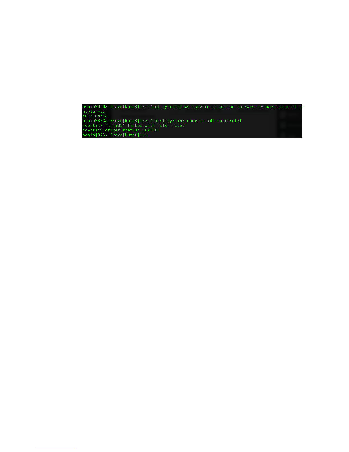
Task: Resolver – Add Rule and Link Identity
1. On the Resolver side, configure a Forward rule for the Protected Resource and link it to
the Identity:
a. /policy/rule/add name=rule1 action=forward
resource=prhost1 enable=yes
b. /identity/link name=tr-id1 rule=rule1
Task: Inserter – Enable Enforce Mode
1. On the Inserter side, run the following command.
a. /context/tac mode=enforce
Task: Resolver – Enable Enforce Mode
1. On the Resolver side, run the following command.
a. /context/tac mode=enforce
90
Page 92

SECTION VIII
91
Page 93
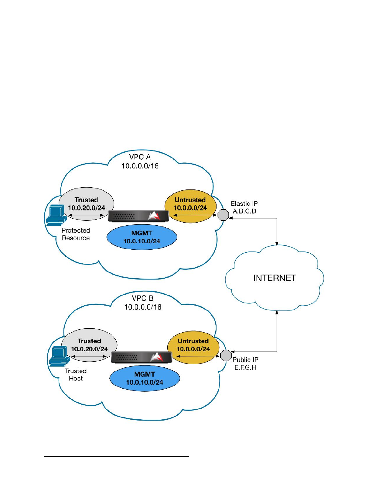
Configure Layer 3 NAT – VPC-to-VPC (Bidirectional)
This section will describe how to configure bidirectional communication between two separate
VPCs in AWS that are protected by BlackRidge TAC Gateways. Specifically, the Gateways will be
configured such that the Trusted+Protected host in VPC A can communicate with the
Trusted+Protected host in VPC B, and vice versa.
The configuration and internal addressing for each VPC in this example is identical. Different
Elastic IPs are assigned for external access to the various components of the VPC.
VPC Network Configuration (Protected Resource)
92
Page 94
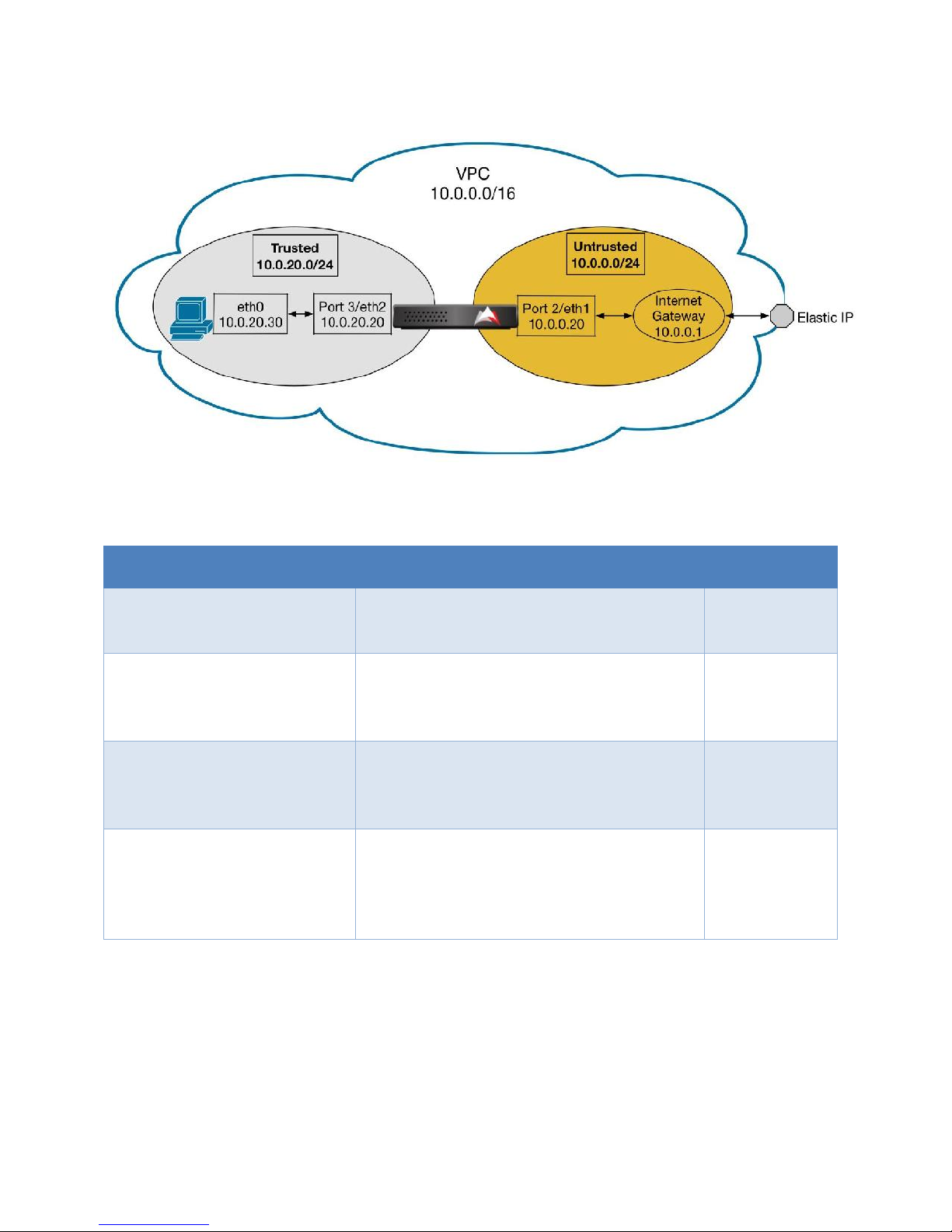
Variable
Description
Value
TRUST_HOST_IP
IP address of the Trusted Host in the
Trusted Subnet; Trusted side of NAT config
10.0.20.30
TRUST_GW_IP
IP address of the Gateway Interface in the
Trusted Subnet; Trusted side of Route
config
10.0.20.20
UNTRUST_GW_IP
IP address of the Gateway Interface in the
Untrusted Subnet; Untrusted side of NAT
config
10.0.0.20
UNTRUST_ROUTER_IP
IP address of the Router Interface in the
Untrusted Subnet used to send traffic out
of the network; Untrusted side of Route
config
10.0.0.1
93
Page 95
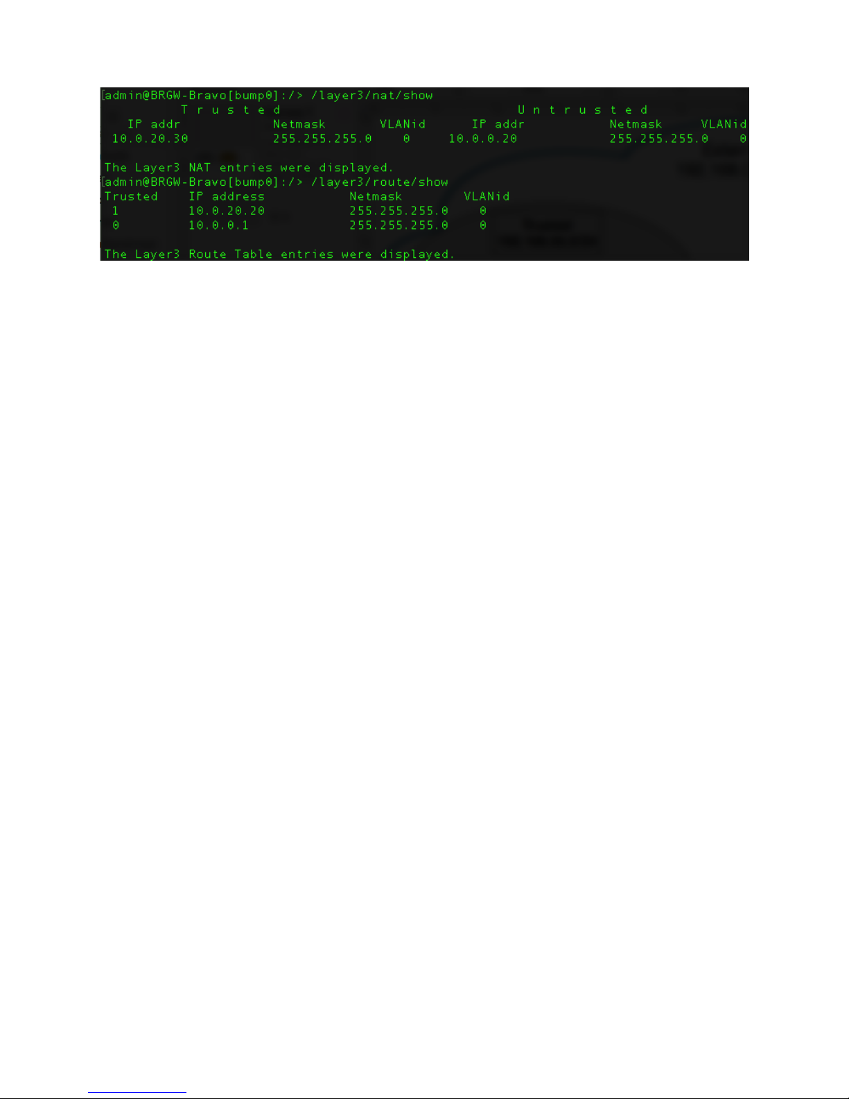
Task: Inserter + Resolver – Add NAT and Routes
The Gateway in each VPC has been configured for Layer 3 NAT mode using the following
commands:
/layer3/nat/add tr_ip=<TRUST_HOST_IP>
tr_netmask=255.255.255.0 tr_vlanid=0 ut_ip=<UNTRUST_GW_IP>
ut_netmask=255.255.255.0 ut_vlanid=0
o TRUST_HOST_IP = IP of the Trusted Host in the Trusted Subnet
o UNTRUST_GW_IP = IP of the Gateway interface in the Untrusted Subnet
/layer3/route/add trusted_flag=y ip=<TRUST_GW_IP>
netmask=255.255.255.0 vlanid=0
o TRUST_GW_IP = IP of the Gateway interface in the Trusted Subnet
/layer3/route/add trusted_flag=n ip=<UNTRUST_ROUTER_IP>
netmask=255.255.255.0 vlanid=0
o UNTRUST_ROUTER_IP = IP of the Router interface in the Untrusted Subnet
/layer3/enable
Note that each Trusted+Protected host in a VPC will require its own Elastic IP, as well as its own
NAT entry via the /layer3/nat/add command above. AWS provides five (5) Elastic IPs free of
charge; usage above that limit will incur additional costs.
94
Page 96
Task: Inserter + Resolver – Configure Trusted Host and
Protected Resource
Trusted Host and Protected Resource entries can be created for the Trusted+Protected host in
each VPC, and referenced in the commands to follow.
1. Trusted Host
/identity/host/add name=trhost1 ip=<UNTRUST_ROUTER_IP>
mask=255.255.255.255 comment="Trusted host for L3."
a. UNTRUST_ROUTER_IP = IP of the Router interface in the Untrusted Subnet
2. Protected Resource
/policy/rule/resource/add name=prhost1
ip=<UNTRUST_ROUTER_IP> mask=255.255.255.255
comment="Protected resource for L3."
a. UNTRUST_ROUTER_IP = IP of the Router interface in the Untrusted Subnet
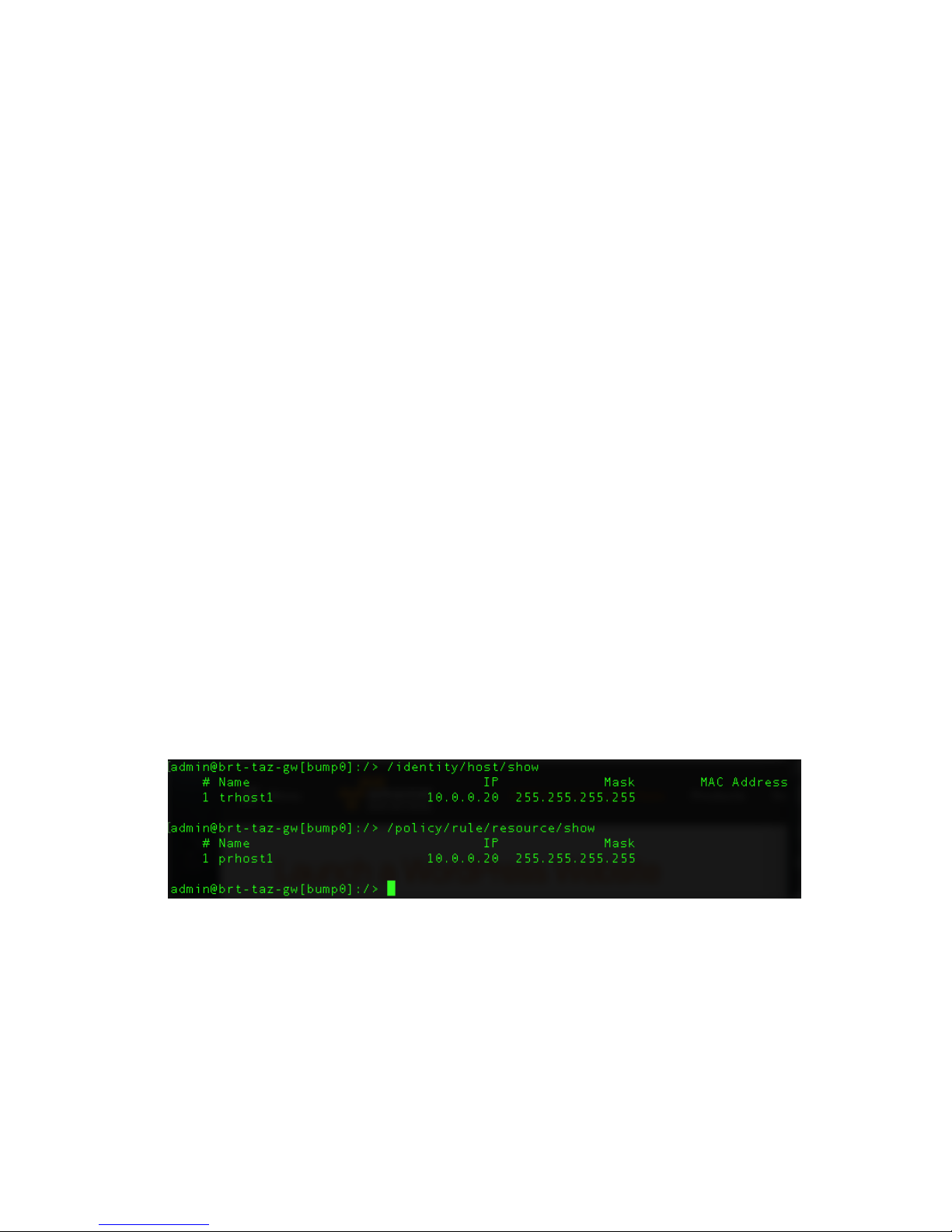
3. Verify the creation/existence of the Trusted+Protected host via the following
commands:
/identity/host/show
/policy/rule/resource/show
Task: Inserter – Generate and Export SKEY
1. SSH into the MGMT interface of the Inserter Gateway as “admin”.
2. Run the following commands:
/identity/skey/generate name=tr_key_Steve
/identity/skey/export name=tr_key_Steve dest=display
95
Page 97
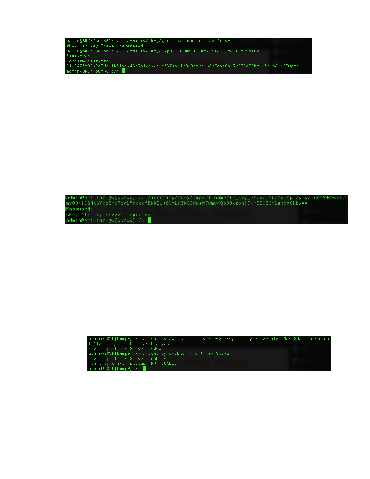
3. When prompted, input a password of your choosing twice to encrypt the skey value.
4. Copy the value printed to screen for use in the next step.
Task: Resolver – Import SKEY
1. SSH into the MGMT interface of the Resolver Gateway as “admin”.
2. Run the following command, using the skey value and password from the previous step:
/identity/skey/import name=tr_key_Steve src=display
value=<displayed key value from above>
Task: Inserter – Add and Enable Identity
1. On the Inserter Side, create and enable a new Identity:
a. /identity/add name=tr-id-Steve skey=tr_key_Steve
alg=HMAC-SHA-256 comment="Identity for L3." enable=yes
b. /identity/enable name=tr-id-Steve
96
Page 98
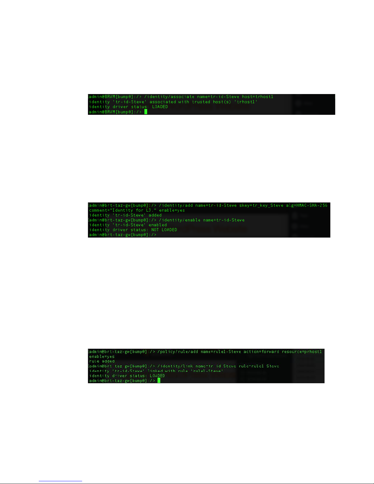
Task: Inserter – Associate Identity with Trusted Host
1. On the Inserter Side, associate the new Identity with the Trusted Host:
a. /identity/associate name=tr-id-Steve host=trhost1
Task: Resolver – Add and Enable Identity Using SKEY
1. On the Resolver side, create and enable a new Identity:
a. /identity/add name=tr-id-Steve skey=tr_key_Steve
alg=HMAC-SHA-256 comment="Identity for L3." enable=yes
b. /identity/enable name=tr-id-Steve
Task: Resolver – Add Rule for and Link Identity to
Protected Resource
1. On the Resolver side, create a Forward rule for the Protected Resource. Then, link the
rule to the Identity:
a. /policy/rule/add name=rule1-Steve action=forward
resource=prhost1 enable=yes
b. /identity/link name=tr-id-Steve rule=rule1-Steve
97
Page 99

Task: Inserter – Enable Enforce Mode
1. On the Inserter side, run the following command:
/context/tac mode=enforce
Task: Resolver – Enable Enforce Mode
1. On the Resolver side, run the following command:
/context/tac mode=enforce
98
Page 100

SECTION IX
99
 Loading...