

Page 1

Specifications & Set-up:
Black Opal Model RMU10HX
Flat Panel Display System
PS-RMU-M-0269-0_1 6.7.06 TW/TW i
Specifications & Set-up
READ THIS DOCUMENT THOROUGHLY BEFORE
ATTEMPTING TO ASSEMBLE OR OPERATE
THE
Black Opal
Multi Function Flat Panel Display System
Model RMU10HX
Treatment of this product other than as specified herein may result in:
damage to the product or attached systems;
invalidation of the warranty.
The location of this document should always be known to all users of, and technical
support personnel for, the Black Opal RMU.
The information contained herein is proprietary to Laserdyne Pty Ltd. No part of this work may be
reproduced or copied in any way without prior written permission of Laserdyne Pty Ltd.
Note: specifications herein are subject to change without notice.
CAUTIONS:
• User-supplied cables must be correctly wired (see Connector/Pin
Details).
• Ensure that external power is within the range specified.
• Ensure that external power is off before proceeding with set-up.
Page 2
Specifications & Set-up:
Black Opal Model RMU10HX
Flat Panel Display System
PS-RMU-M-0269-0_1 6.7.06 TW/TW ii
Tracking Records
This document is appropriate for the following product
configurations:
Model:
Black Opal Model:
RMU10HX.
Initial Installed Software Version:
4.5
Page 3

Specifications & Set-up:
Black Opal Model RMU10HX
Flat Panel Display System
PS-RMU-M-0269-0_1 6.7.06 TW/TW iii
TABLE OF CONTENTS
Chapter Page
1 SYSTEM SPECIFICATIONS 1-1
1.1 System Performance 1-1
1.2 Controls 1-2
1.3 Communications 1-3
1.4 Physical Characteristics 1-3
1.5 Electrical Requirements 1-3
1.6 Environmental 1-4
1.7 Connector/Pin Details 1-4
2 SET-UP 2-1
2.1 Mounts 2-1
2.2 Connections 2-1
2.3 Set-up Procedure 2-2
2.4 Heating and Cooling 2-3
LIST OF FIGURES
Figure 2-1: Mounts 2-1
Figure 2-2: Connections 2-2
Page 4
Specifications & Set-up:
Black Opal Model RMU10HX
Flat Panel Display System
PS-RMU-M-0269-0_1 6.7.06 TW/TW 1-1
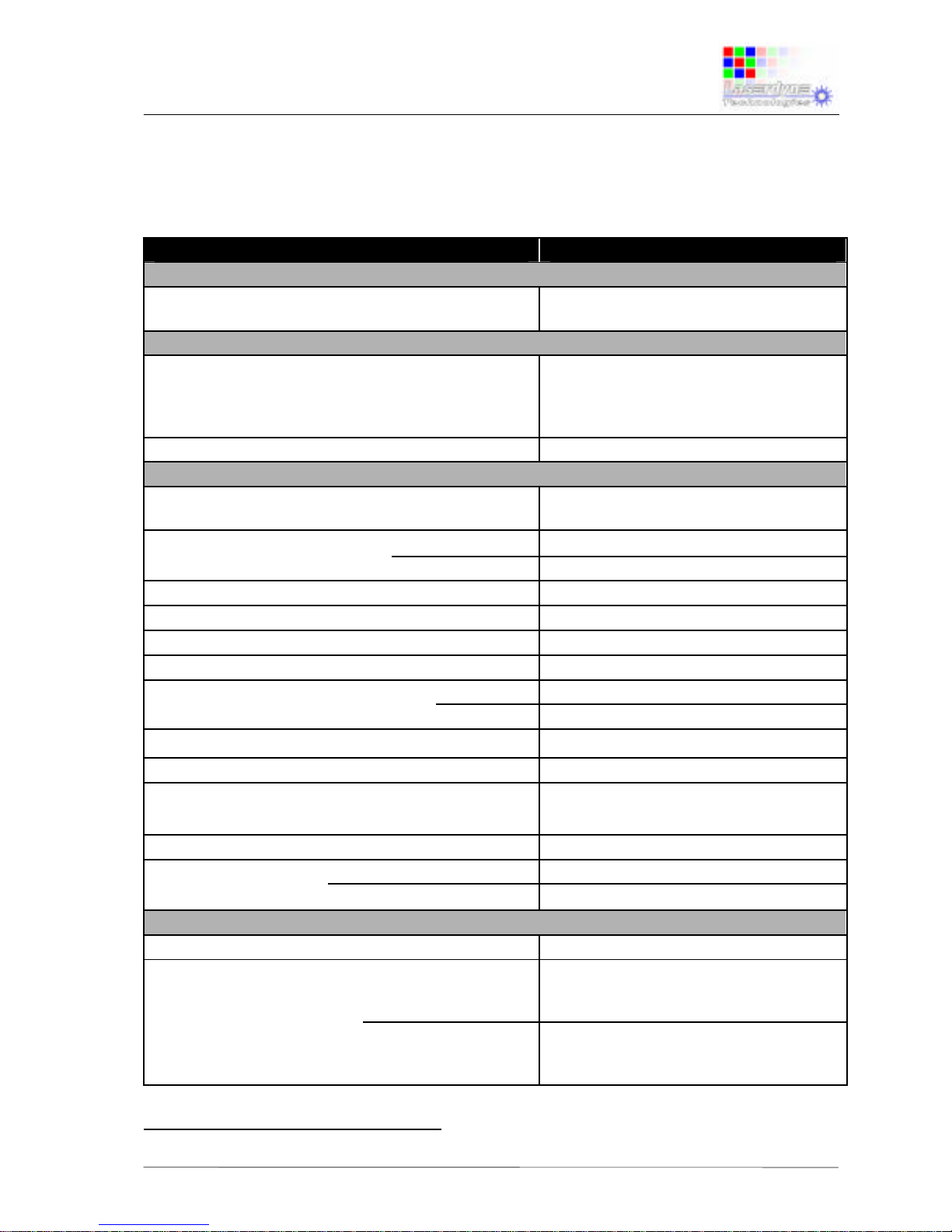
1 SYSTEM SPECIFICATIONS
1.1 System Performance
PARAMETER SPECIFICATION
Designation
RMU10HX Remote Monitor Unit, 10”, High
brightness, XGA
Control
Control Functions [factory configurable to
customer requirements]
power On/Off; backlight intensity;
menu select; select screen lay-out;
select image enhancement feature;
digital zoom; freeze frame
Controls
tactile 8-button membrane
Display
Type Active Matrix Colour (18-bit colour)
LCD Module
Display Size (″ {cm})
diagonal
10.4 {26.42}
active area
8.31 {21.1} x 6.24 {15.8}
Aspect Ratio [width:height]
4:3
Pixel Number [1 pixel is RGB trio]
1,024 x 768
Colour
262k [6-bit each colour]
Grey Scale
256 [8-bit]
Backlight Luminance [CCFT type; minimum
0
approx.; adjustable] (cdm-2) 1 maximum
1,700
Contrast Ratio [limiting; LCD]
300:1
Response Time [max.] (ms)
50
Readability [ambient conditions]
black-out to full direct sunlight
[105 lux]
Night Vision Device compatible?
yes [low intensity green]
Viewing Angle vertical
+40/-35
[full angle] (°)
horizontal
±55
Inputs
Inputs
2 video and 1 PC [4 and 1 optional]
Signal Formats video PAL [all forms], NTSC [all forms],
SECAM [all forms], CCIR-601, RS170;
interlaced and non-interlaced
PC non-interlaced, 60Hz, RGB, separate
Hsync. & Vsync., up to 1,024 x768
[standard PC XGA]
1
1 cdm-2 = 1 nit.
Page 5
Specifications & Set-up:
Black Opal Model RMU10HX
Flat Panel Display System
PS-RMU-M-0269-0_1 6.7.06 TW/TW 1-2
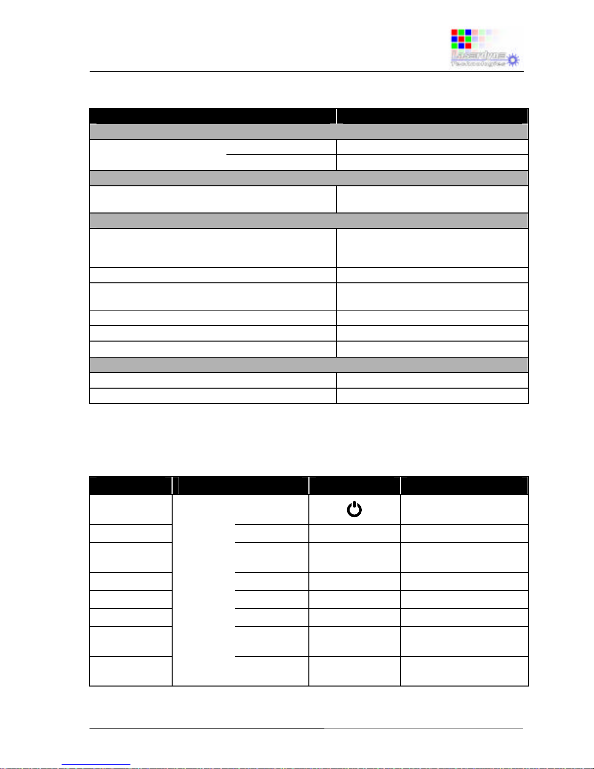
1.1 System Performance (cont’d)
PARAMETER SPECIFICATION
Inputs (cont’d)
Connection Formats video
Composite, S-Video [Y-C]
PC
RGB + Hsync. + Vsync.
Outputs
Video prime video input is output [what
comes in goes out]
Safety & Protection
Cooling thermal transfer by internal and
external convection; cooling fin fitted to
rear
Backfill
purged & backfilled [N2]
Display Window Antireflection, hard-coated, sealed,
EMI/EMC shielded
Altitude/Decompression
pressure relief valve, 2-way
Electrical Protection
conforms to QSTAG 307
Audible Emission [@ ≥ 10m]
nil
Support
MTBF (hours)
> 8,000
Operational Life (years)
10
1.2 Controls
Control Type Location Primary Label Primary Function
Button
membrane
on left of
top
toggle between active
and standby
Button
front face 2nd top
1
menu
Button
3rd top
2
show assigned screen
lay-outs for selection
Button
middle
3
enhance
Button
3rd bottom
4
zoom
Button
2nd bottom
5
freeze
Button
bottom left
-
backlight down;
scroll/adjust down
Button
bottom right
+
backlight up;
scroll/adjust up
Page 6
Specifications & Set-up:
Black Opal Model RMU10HX
Flat Panel Display System
PS-RMU-M-0269-0_1 6.7.06 TW/TW 1-3
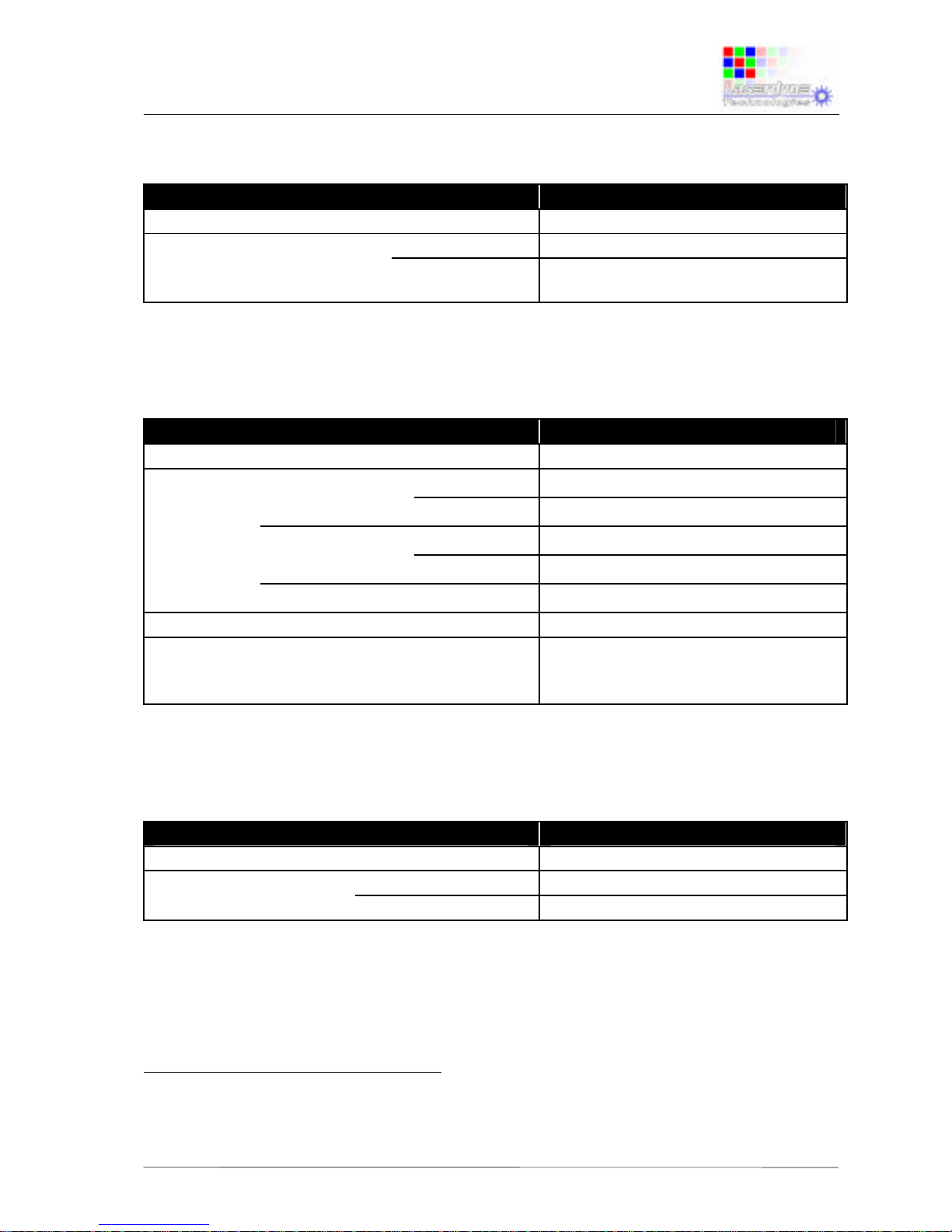
1.3 Communications
PARAMETER SPECIFICATION
Ports
one Serial port 2
Data Format
RS232 [RS422 optional]
Rate (Baud) 9,600 [1,200 to 230.6k optional; or to
10 Mbaud for RS422]
1.4 Physical Characteristics
PARAMETER SPECIFICATION
Mass [approx.] (kg)
4.7
Dimensions Width body
281
(mm) overall 3
307
Height body
211
overall
3
229
Depth 4
96
Specific Gravity
>1 [non-floatation]
Mounting 5
Dzus fasteners x 6 [type PFSC35] or
or 2-way adjustable mounting bracket
optional
1.5 Electrical Requirements
PARAMETER SPECIFICATION
Supply Voltage (Vdc)
20 to 33 [28 nominal]
Current Drain heater on
< 3
[@ 28Vdc; typical] (A) heater off
< 2
2
Shared with power input.
3
Including mounting flange.
4
Excluding connectors.
5
Optional 2-way adjustable mounting bracket has four ¼” clearance holes for mounting
Page 7
Specifications & Set-up:
Black Opal Model RMU10HX
Flat Panel Display System
PS-RMU-M-0269-0_1 6.7.06 TW/TW 1-4
1.6 Environmental
PARAMETER SPECIFICATION
Temperature (°C)
Operate 6 min.
-25 [without wind-chill]
max.
+55 [without solar radiation]
Survive min.
-30 [without wind-chill]
max.
+71 [without solar radiation]
Vibration and Shock
MIL-STD-810E, aircraft 7
Sealing 8
water resistant [drip & spray]
EMI/EMC 8
MIL-STD-461D
7
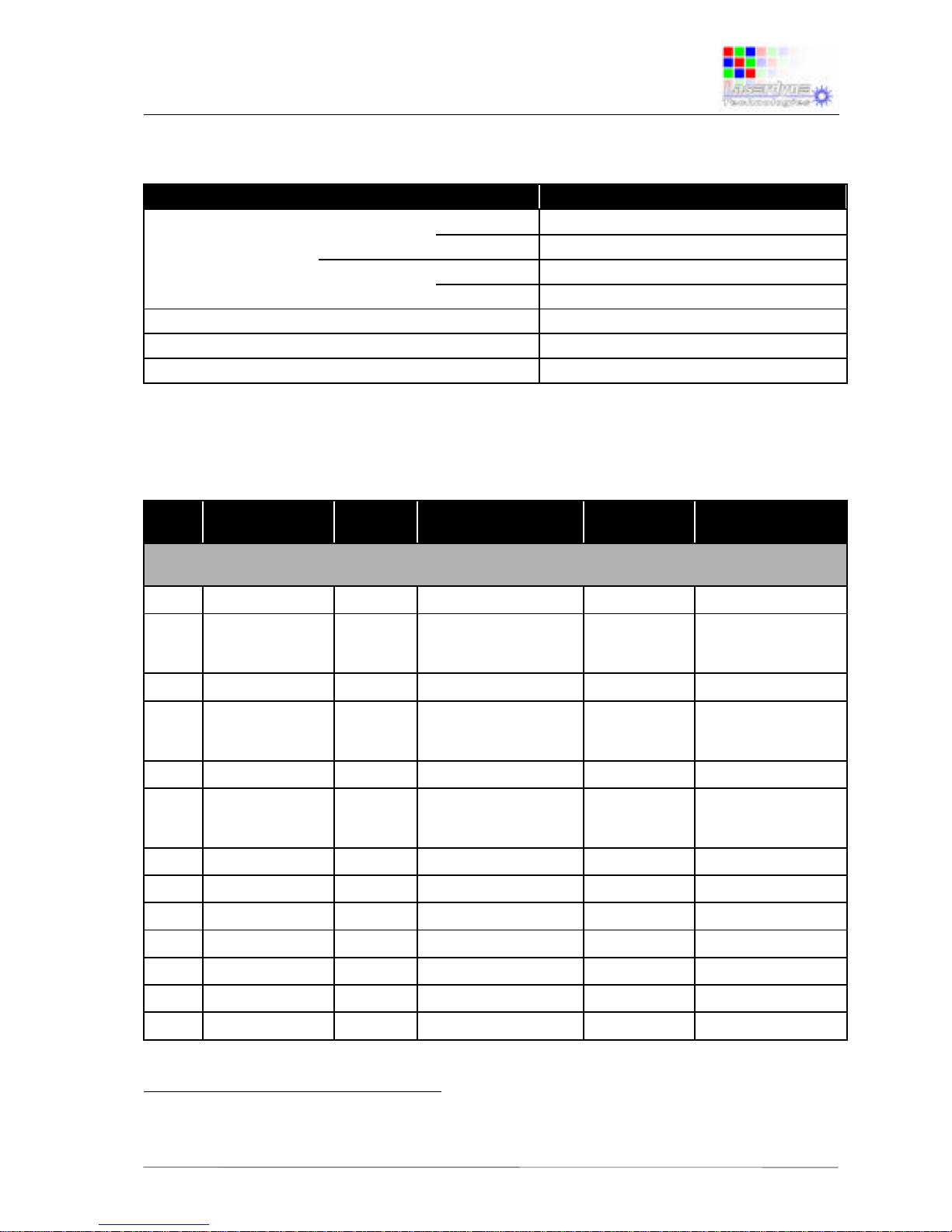
1.7 Connector/Pin Details
No. Name Pin
Marking
Purpose Notes for
Harness
Comment
A: VGA Input: Connector, MilSpec, Mil-C26482, Panel, Plug, Bayonet, 19 Way, 14 Shell, Pattern 105,
square flange, AB05 2100 14-19P N00
A1 RED OUT
A N/A
A2 RED IN
B RED INPUT
coax (B,P), 75Ω
DB15 pin 1. Also Pr
input for component
video
A3 GREEN OUT
C N/A
A4 GREEN IN
D GREEN INPUT
coax (D,R), 75Ω
DB15 pin 2. Also Y
(and SOG) input for
component video
A5 BLUE OUT
E N/A
A6 BLUE IN
F BLUE INPUT
coax (F,S), 75Ω
DB15 pin 3. Also Pb
input for component
video
A7 HS OUT
G N/A
A8 HS IN
H HSYNC INPUT signal wire DB15 pin 13
A9 VS OUT
J N/A
A10 VS IN
K VSYNC INPUT signal wire DB15 pin 14
A11 DDC_5V
L DDC CHANNEL +5V unused DB15 pin 9
A12 DDC_SDA
M DDC CHANNEL DATA unused DB15 pin 12
A13 DDC_SCL
N DDC CHANNEL CLOCK unused DB15 pin 15
6
When used in accordance with procedures in User’s Manual.
7
Contact supplier for details.
8
With compliant line connectors attached.
Page 8
Specifications & Set-up:
Black Opal Model RMU10HX
Flat Panel Display System
PS-RMU-M-0269-0_1 6.7.06 TW/TW 1-5
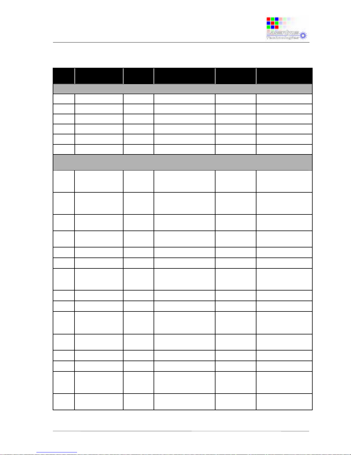
1.7 Connector/Pin Details (cont’d)
No. Name Pin
Marking
Purpose Notes for
Harness
Comment
A: VGA Input (cont’d)
A14 RED GND
P RED coax GND coax braid DB15 pin 6
A15 GREEN GND
R GREEN coax GND coax braid DB15 pin 7
A16 BLUE GND
S BLUE coax GND coax braid DB15 pin 8
A17 DIGITAL GND
T HSYNC GND signal wire DB15 pin 5
A18 DIGITAL GND
U VSYNC GND signal wire DB15 pin 10
A19 N/C
V UNUSED unused DB15 pin 4,11
B: Video Input: Connector, MilSpec, Mil-C26482, Panel, Socket, Bayonet, 19 Way, 14 Shell, Pattern
105, square flange, AB05 2100 14-19S N00
B1 Y1_GND
A Primary video
(composite or luma)
GND
coax, 75Ω
shield
B2 Y1_SIGNAL
B Primary video
(composite or luma)
input
coax, 75Ω
center
75Ω terminated in
display
B3 Y2_GND
C Secondary video
(composite or Y) GND
coax, 75Ω
shield
B4 Y2_SIGNAL
D Secondary video
(composite or Y) input
coax, 75Ω
center
75Ω terminated in
display
B5 RS485+
E RS485+ connection signal
B6 RS485-
F RS485- connection signal
B7 V-
G dc- (GND) connection 5A dc internally isolated
from comms and
video GND.
B8 V+
H Output power (+28V) 5A dc Same as input dc
B9 V+
J Output power (+28V) 5A dc Same as input dc
B10 VIDEO_OUT
K Switched video output
coax, 75Ω
center
either Y1 or Y2
output, 75Ω double
terminated
B11 GND_OUT
L Video output GND
coax, 75Ω
shield
B12 SPARE1
M Analogue input signal
SPARE1
B13 SPARE2
N Analogue input signal
SPARE2
B14 C1_SIGNAL
P Primary chroma input
[or VCR composite
input]
coax, 75Ω
center
75Ω terminated in
display
B15 C2_SIGNAL
R Secondary chroma
input
coax, 75Ω
center
75Ω terminated in
display
Page 9
Specifications & Set-up:
Black Opal Model RMU10HX
Flat Panel Display System
PS-RMU-M-0269-0_1 6.7.06 TW/TW 1-6
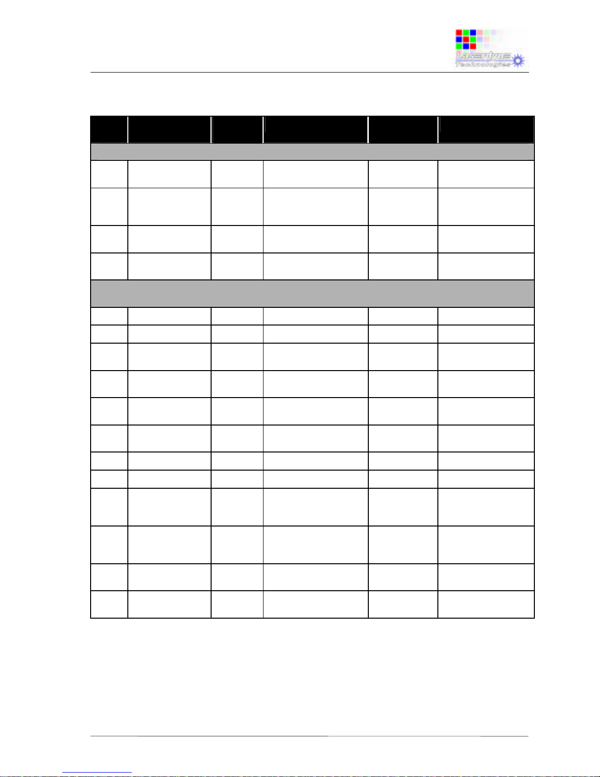
1.7 Connector/Pin Details (cont’d)
No. Name Pin
Marking
Purpose Notes for
Harness
Comment
B: Video Input (cont’d)
B16 C_GND
S Chroma common [or
VCR composite input]
coax, 75Ω
shield
B17 V-
T dc- (GND) connection 5A dc internally isolated
from comms and
video GND.
B18 RS232_TX
U RS232 transmit
(output from display)
signal
B19 RS232_RX
V RS232 receive (input
to display)
signal
C: dc Power Input & Comms Port Connection: Connector, MilSpec, Mil-C26482, Panel, Plug, Bayonet,
12 Way, 14 Shell, Pattern 105, square flange, AB05 2100 14-12P N00
C1 COMMS_GND
A common for comms signal
C2 N/C
B unused
C3 RS232_RX
C RS232 receive (input
to display)
signal
C4 RS232_TX
D RS232 transmit
(output from display)
signal
C5 nRESET
E active low display
reset control
reserved
C6 MODAB
F active low display
bootload control
reserved
C7 RS485-
G RS485- connection reserved
C8 RS485+
H RS485+ connection reserved
C9 V-
J dc- (GND) connection 5A dc internally isolated
from comms and
video GND.
C10 V-
K dc- (GND) connection 5A dc internally isolated
from comms and
video GND.
C11 V+
L Input power (+28V)
for display
5A dc +20..+33V input
C12 V+
M Input power (+28V)
for display
5A dc +20..+33V input
Page 10
Specifications & Set-up:
Black Opal Model RMU10HX
Flat Panel Display System
PS-RMU-M-0269-0_1 6.7.06 TW/TW 2-1
2 SET-UP
2.1 Mounts
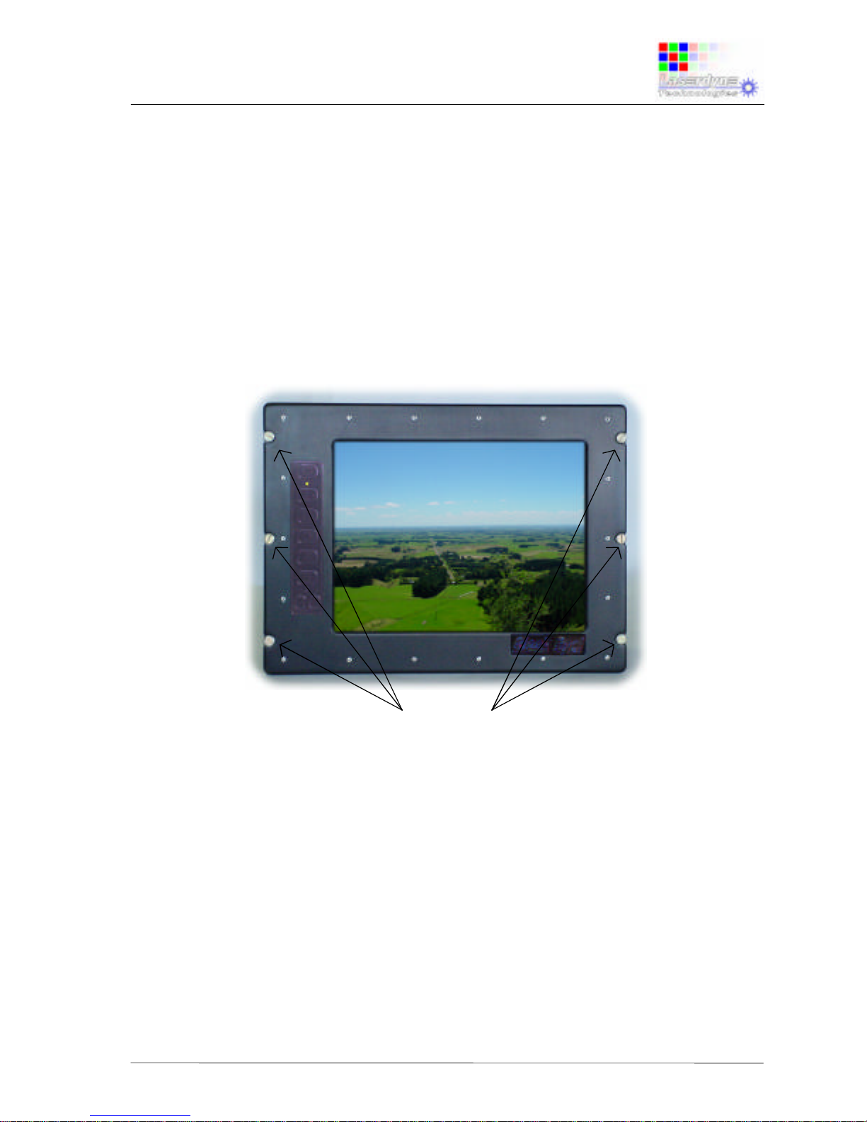
The RMU has two optional mounting methods:
six type PFSC35 Dzus fasteners, located on the left and right (three per
side) of the mounting flange; or
a 2-way adjustable mounting bracket fitted to the RMU.
In the case of the 2-way adjustable mounting bracket, four mounting points are
provided, being ¼” diameter clearance holes located in the top section of the
bracket.
Figure 2-1: Mounts
2.2 Connections
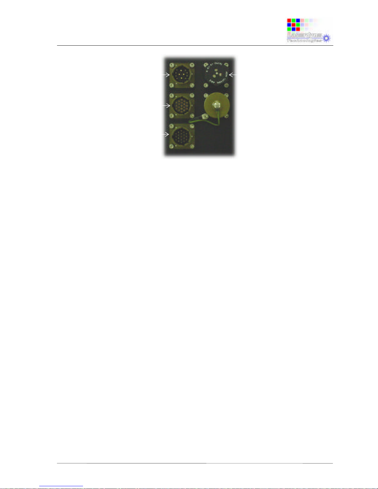
The RMU has three connection points located on the rear of the unit:
Connector A, the VGA Input connector;
Connector B, the Video Input connector; and
Connector C, the dc Power Input & Comms Port connector.
mounting
points
Page 11
Specifications & Set-up:
Black Opal Model RMU10HX
Flat Panel Display System
PS-RMU-M-0269-0_1 6.7.06 TW/TW 2-2
Figure 2-2: Connections
2.3 Set-up Procedure
CAUTION: User-supplied cables must be correctly wired (see list of
Connector/Pin Details).
Ensure that external power is within the range specified
herein.
Ensure that external power is OFF before proceeding with
set-up.
• Mount the unit to the vehicle or platform, using the six Dzus fasteners provided.
• Connect the required video cable to Connector B and to the external imaging
system(s).
• Connect the required VGA cable to Connector A and to the external VGA source.
• Connect the required power/data cable to Connector C and to the external power
source, and to the communication data source (RS232).
Connector C, Power
Input & Comms (12
way)
Connector B, Video
Input (19 way)
Connector A, VGA
Input (19 way)
Pressure Relief
Valve
Page 12
Specifications & Set-up:
Black Opal Model RMU10HX
Flat Panel Display System
T:\PROD&PRO\SPECS\PS-RMU-M-0269-0_1 6.7.06 TW/TW 2-3
2.4 Heating and Cooling
The unit contains internal heating and cooling mechanisms that are triggered at
certain internal temperatures.
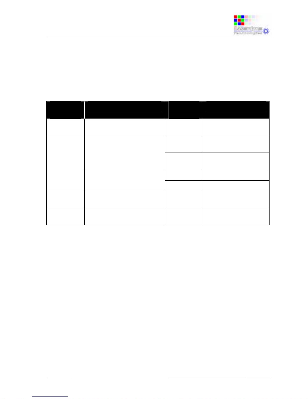
The operating procedures, internal temperatures and resulting operating conditions
are shown in the following table.
Ambient
Temp. (°C)
Procedure Internal
Temp. (°C)
Operating Condition
< -46 do not attempt to operate
unit
-46 to 0 de-ice unit prior to start-up
≤ 0
unit will not power up;
heater on
> 0 unit will power up;
internal convection on
0 to +55 none
≥ 10
heater off
≥ 55
backlight reduces
+55 to +60 provide forced air cooling
(e.g. fan)
> +60 do not attempt to operate
unit
≥ 75
unit will not power up
The approximate warm-up rate is 17s/°C (e.g. with starting internal temperature of 46°C, unit will power up in about 13 minutes; with starting internal temperature of 25°C, unit will power up in about 7 minutes).
Once the unit has warmed it will operate normally provided that the ambient
temperature stays within the specified operating temperature range. Otherwise the
heater will remain on.
 Loading...