

BLACKMER HD161A, HD162A, HD163A, HD361A, HD362A Installation, Operation & Maintenance Instructions Manual
...Page 1

COMPRESSORS CB9A-020 2009/10
INSTALLATION, OPERATION & MAINTENANCE INSTRUCTIONS
DISCONTINUED MODELS
HD161A HD162A HD163A
HD361A HD362A HD363A
HD601A HD602A HD603A
WARNING
THIS PRODUCT MUST ONLY BE INSTALLED IN
SYSTEMS WHICH HAVE BEEN DESIGNED BY THOSE
QUALIFIED TO ENGINEER SUCH SYSTEMS. THE
SYSTEM MUST BE IN ACCORDANCE WITH ALL
APPLICABLE REGULATIONS AND SA FETY COD ES
AND WARN OF ANY HAZARDS UNIQUE TO THE
PARTICULAR SYSTEM.
WARNING DANGER
DO NOT ATTEMPT TO OPEN THE COMPRESSOR
UNTIL YOU HAVE BLED OFF ALL PRESSURE. THE
COMPRESSOR VALVES MAY HOLD PRESSURE
INDEFINITELY IN THE DISCHARGE PIPING
CAUTION:
IF SYSTEM IS TO BE HYDROSTATICALLY TESTED,
COMPRESSOR MUST BE ISOLATED. WATER
ENTERING THE UNIT CAN CAUSE CORROSION AND
DAMAGE.
NOTE NAMEPLATE DATA HERE
MODEL: HD
ID#:
SERIAL NUMBER:
Before proceeding:
1. Note the nameplate data in the space provided above.
2. Obtain the appropriate parts lists for the model in question.
3. These compressors are used on a wide variety of gasses.
Before doing any work on the compressor, be certain of the identification of the
gas and the precautions to be followed when around that gas.
TABLE OF CONTENTS
GENERAL INFORMATION.............................2
Compressor Data
Nameplate Data
Maximizing Compressor Life
Suction Valve Unloaders
Seal Arrangements
OPTIONAL COMPONENTS...........................6
Relief Valves
Liquid Traps
Temperature and Pressure Switches
INSTALLATION ..............................................7
Location and Piping
Mounting the Compressor Unit
OPERATION ...................................................8
Pre-Start up Check List
Start Up Procedure
MAINTENANCE..............................................9
Routine Service Schedule
Tool List
Bolt Torque Table
Crankcase Lubrication / Oil Capacity
Rotation Direction
Compressor Disassembly
Compressor Assembly
Valve Replacement
Unloader Seal Replacement
Piston Ring Replacement
Seal (Packing) Replacement
Bearing Replacement
Oil Pump Replacement
EXTENDED STORAGE PROCEDURES......23
TROUBLESHOOTING..................................24
www.blackmer.com
Page 2
GENERAL INFORMATION
COMPRESSOR DATA
Air Cooled
Single-Seal Models
Double-Seal Models
Triple-Seal Models
Displacement
@ 350 rpm - CFM (m
@ 825 rpm - CFM (m
Max. BHP (kw) 10 (7.5) 15 (11) 40 (30)
MAWP - psia (kPa) 350 (2,413)
Maximum Discharge Temperature
Type: Single-stage, vertical, air-cooled reciprocating with single acting cylinders.
NOTE: Reduce maximum speeds by 9% for continuous duty operation.
3
/hr)
3
/hr)
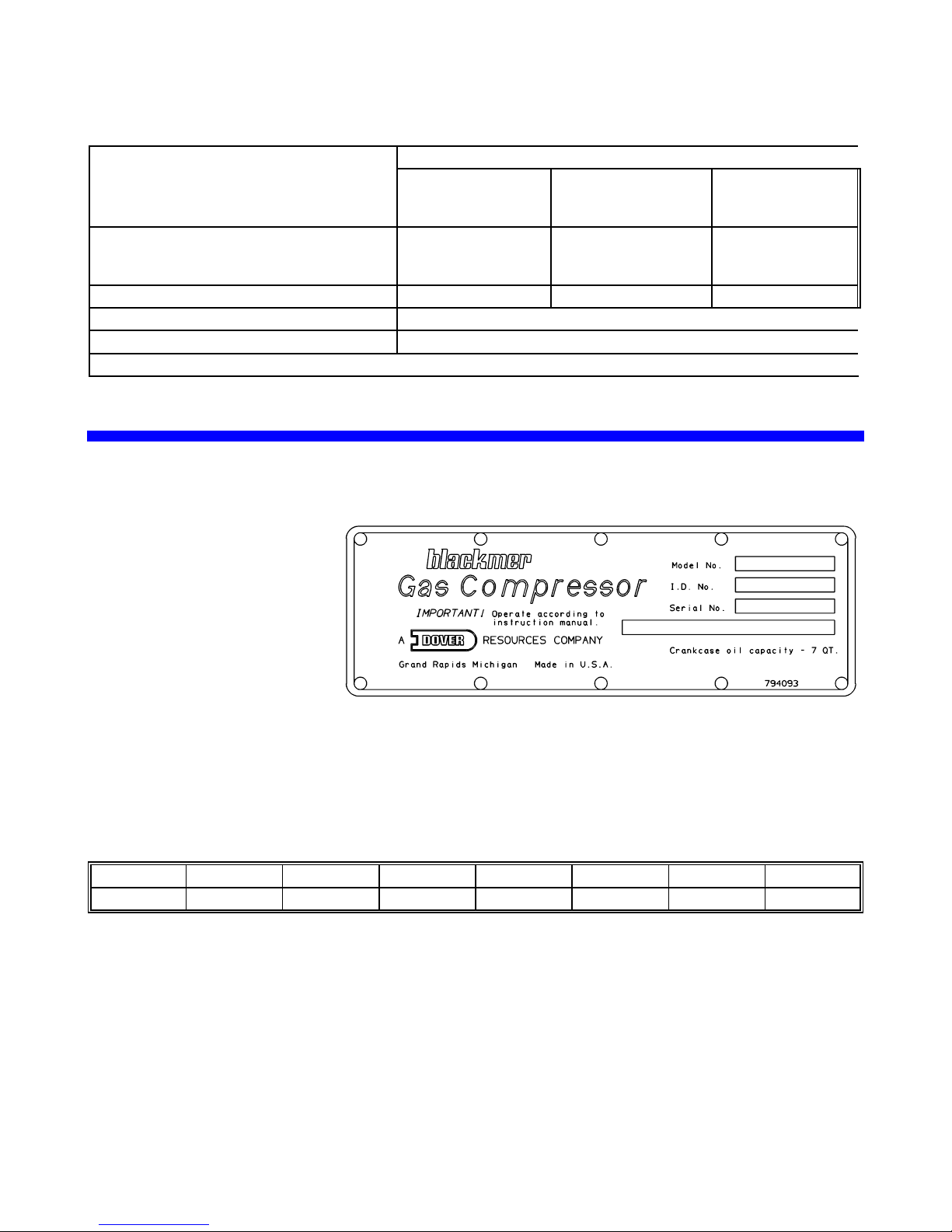
NAMEPLATE DATA
A nameplate is attached to the
side of all Blackmer compressors
showing the Model No., I.D. No.,
and Serial No. These numbers
should be available when
information or parts are needed
for a particular unit.
Model No. Indicates the basic
size and type of the compressor.
A suffix letter is used on most models to indicate the version.
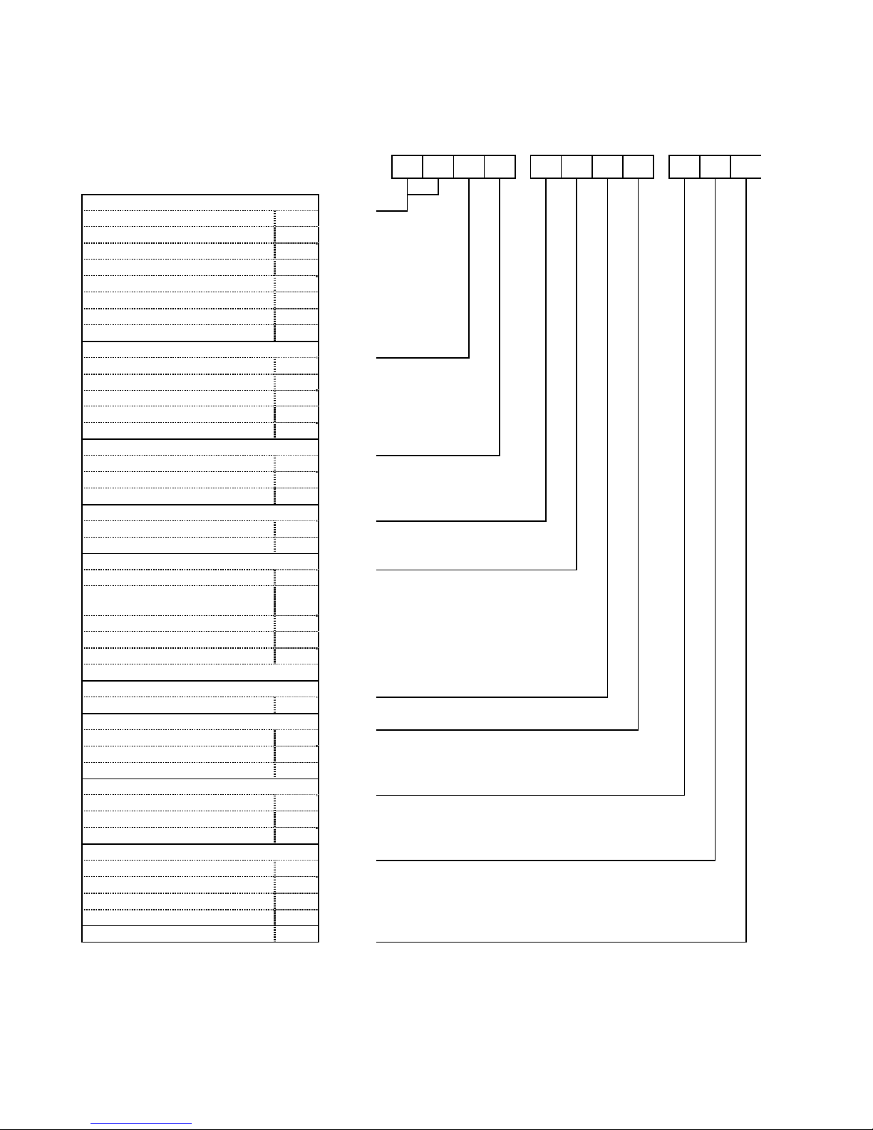
I.D. No. An 11 character code identifies the construction of the compressor. A key to the I.D. Number is found
on the next page.
Serial No. 6 digits and a suffix letter indicating the year of manufacture.
Suffix L M N P Q R S
Year 1991 1992 1993 1994 1995 1996 1997
HD161A
HD162A
HD163A
7.16 (12.2)
16.9 (28.7)
HD361A
HD362A
HD363A
15.3 (26.0)
36.0 (61.2)
350°F (176°C)
HD601A
HD602A
HD603A
27.2 (46.3)
64.2 (109.0)
CB9A-020 page 2
Page 3
GENERAL INFORMATION
HD SINGLE-STAGE COMPRESSORS
ID NUMBER KEY
VALVES Code Fields
TNT-12 steel BE 1 & 2
TNT-12 steel w/ Unloaders BF
Ductile Iron / PEEK PB
DI/PEEK w/ Unloaders PC
TNT-12 DI/PEEK PE
TNT-12 DI/PEEK w/ Unloaders PF
Stainless Steel SB
SS w/ Unloaders SC
O-RINGS Field 3
Buna-N B
Neoprene N
PTFE T
FKM V
Ethylene-Propylene E
GASKETS Field 4
Aluminum A
Iron F
Copper C
PISTON RINGS Field 5
Glass & Moly Filled M
Poly Filled PTFE A
SEAL (PACKING) ORIENTATION Field 6
All Lips up 1
Top Lips Down, Bottom Up
Tube to Stage 1 outlet
Top Lips Up, Bottom Down 3
Up, Down, Up 5
Down, Down, Up 6
Down, Up, Up 7
SEAL MATERIAL Field 7
PTFE T
CYLINDER & HEAD Field 8
Ductile Iron A
TNT-12 DI Cylinder B
TNT-12 DI Cyl. & Head C
PISTON RODS Field 9
Chrome Plated Steel 1
CrO2 Coated Steel 3
Black Surface Steel 4
CRANKSHAFT & OIL FILTER Field 10
Standard A
Extended Crankshaft B
Spin-on Oil Filter C
Ext. Crank & Oil Filter D
OTHER A Field 11
Notes: A 'Z' in any field indicates a non-standard option.
No model is available with all shown options.
2
P B B F
M 1 T A
1 A A
CB9A-020 page 3
Page 4
GENERAL INFORMATION
MAXIMIZING COMPRESSOR LIFE
Life of critical compressor components such as piston rings, valves and packing will vary considerably with each
application, installation, and operating procedures. Premature failure of wear parts can often be attributed to
one the following causes:
1. Excessive Temperatures
Primary causes are:
Operating at pressures other than those originally specified.
Handling a different gas than originally specified.
Clogged strainer or filter elements.
Line sizes too small, or other flow restrictions.
Excessive ambient temperature or suction gas temperature.
Cooling water temperature too high, or coolant flow too low.
Valve problems (see Foreign Material below).
Badly worn piston rings (see Foreign Material below).
Lower operating temperatures will significantly increase valve and piston ring life.
2. Foreign Material
Solid particles in the gas stream will:
Rapidly wear the piston rings and score the cylinder wall.
Destroy the rod packing causing excessive leakage and score the piston rods.
Lodge in the valves causing loss of capacity and broken valve plates and springs.
Liquid in the gas stream will:
Cause broken valve plates and springs.
Destroy the compressor if present in sufficient quantity.
On new installations, it is suggested that the valves and piston rings be inspected after the first few hundred
hours of operation. This will give an early indication of any abnormal problems and allow for corrective action to
be taken before a costly failure results. Although piston ring life will vary from application to application, wear
will be fairly consistent on subsequent sets of rings.
SUCTION VALVE UNLOADERS
Compressors may be fitted with suction valve unloaders to provide loadless start or capacity control functions.
Blackmer unloaders are basically a piston and a plunger atop the suction valve. When pressure is applied to
the top of the unloader piston, it and the plunger move downward, pushing the suction valve off its seat and
unloading the compressor. When the pressure signal is removed, the unloader spring pushes the piston and
plunger back up and the suction valve will resume normal operation.
In order for the unloaders to function, the unloader pressure must be at least 30 psi (207 kpa) above suction
pressure.
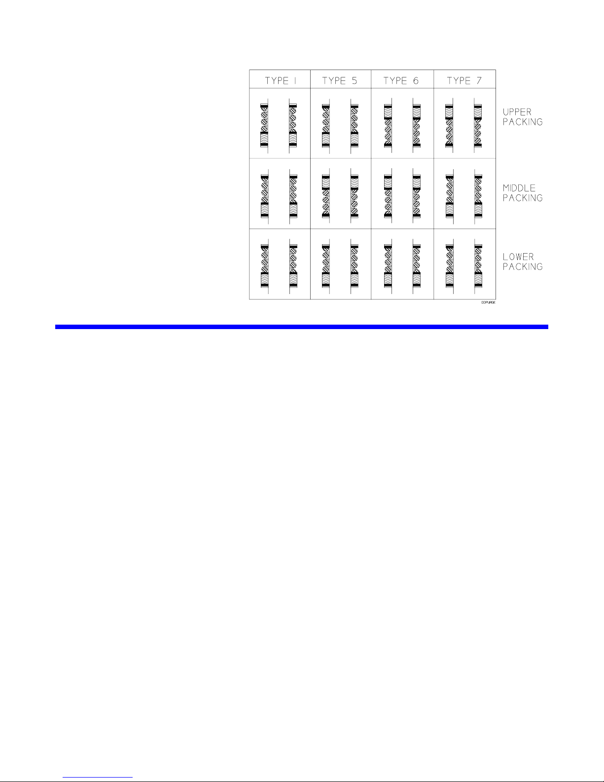
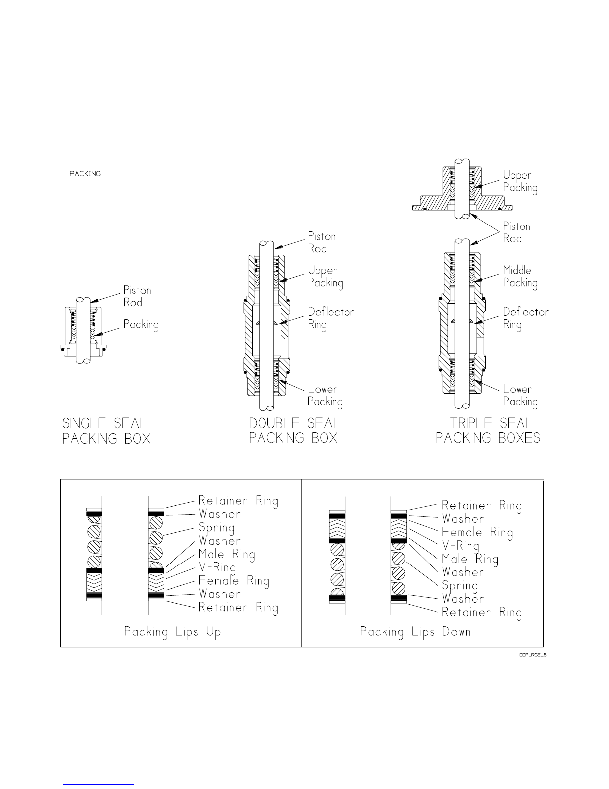
SEAL (PACKING) ARRANGEMENTS
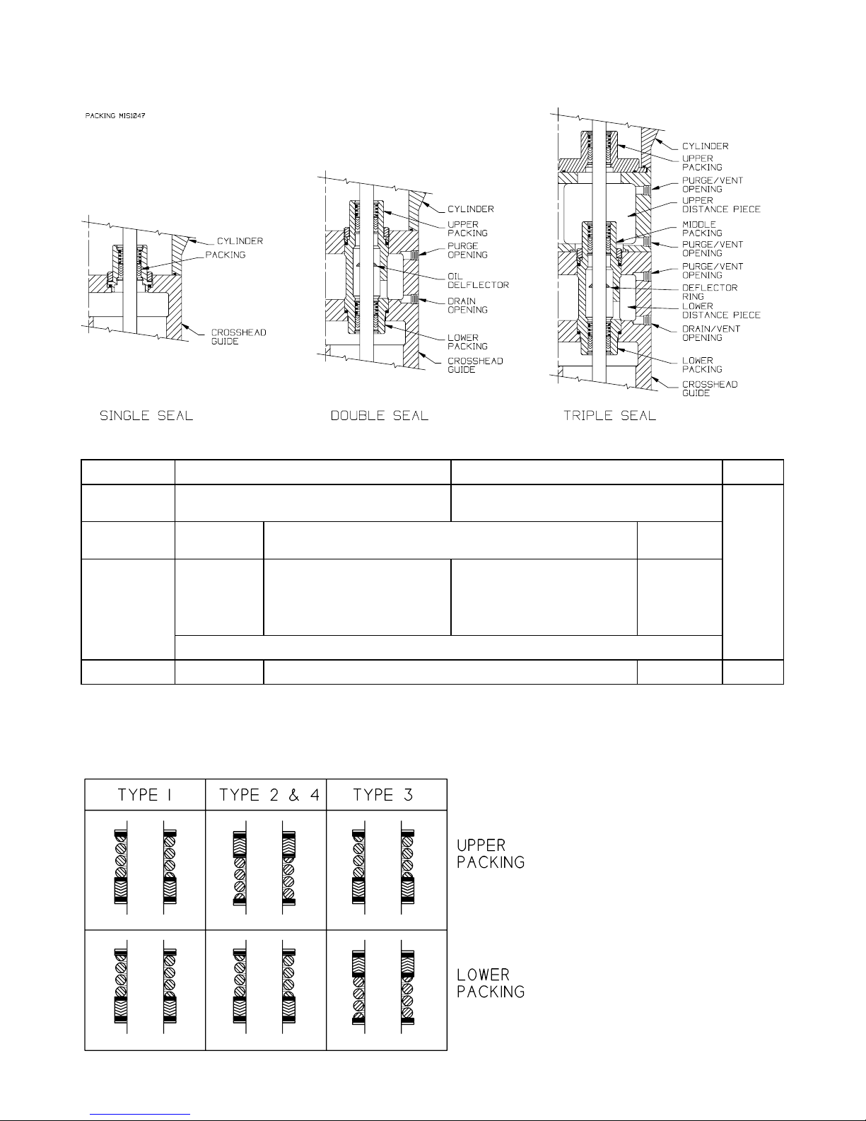
Single, Double and Triple Seal models are available to provide
a wide range of leakage control/containment options. Before
starting work on the compressor, note the seal orientation
indicated by the 6
compressor's nameplate. Also note any tubing connections in
the seal area. 1/4" NPT ports are provided between each pair
of seals to allow proper venting or pressurization of the seal
areas (double and triple seal models only).
SEAL ORIENTATION -
SINGLE SEAL COMPRESSORS
th
digit of the Compressor ID # shown on the
CB9A-020 page 4
Page 5
GENERAL INFORMATION
TYPICAL SEAL AREA CONSTRUCTION
SEAL ARRANGEMENTS - ALL DOUBLE SEAL COMPRESSORS
Type 1 2 3
Inlet
Pressure
Service General Gas
Upper
Distance
Piece
Connections
Lower Install drain valve. Drain accumulated condensate or oil weekly.
Ref. Notes: a b a c
a. Standard Configuration - use when no purge gas is available, or when mixing of the purge gas with
the product stream is not desirable.
b. Use when no external product leakage is desirable.
Note: Mixing of inert pressurization gas and the product stream is likely to occur.
c. Consult Factory.
Atmospheric Pressure or above Vacuum to 25 psia
Transfer
Plugged Purge with Inert gas below suction
pressure and above atmospheric
Toxic, Flammable or otherwise Hazardous Gases General Gas
Pressurize
pressure,
or
Vent to a safe location
Purge with an Inert gas above
suction pressure and above atmos-
or
pheric pressure
SEAL ORIENTATION –
DOUBLE SEAL COMPRESSORS
Transfer
Connect to:
1st-Stage
Discharge
Special
CB9A-020 page 5
Page 6
SEAL ORIENTATION –
ALL TRIPLE SEAL COMPRESSORS
GENERAL INFORMATION
OPTIONAL COMPONENTS
RELIEF VALVES
If a relief valve is not installed by the factory or the purchaser, one must be installed prior to compressor
startup. The relief valve should be installed in the discharge line between the compressor head and the first
block valve.
The type of relief valve should be appropriate to the application. Blackmer offers three relief valves for gas
compatibility: brass for LP-Gas service; aluminum for anhydrous ammonia; A.S.M.E. steel for both services,
and other applications.
The relief valve must be of a type, material and pressure rating suitable to the installation.
LIQUID TRAPS
Compressors handling gasses that contain condensates or other liquids must be protected from entry of the
liquid. LIQUID IN A COMPRESSOR CYLINDER CAN CAUSE DESTRUCTION OF THE COMPRESSOR.
Blackmer offers a variety of liquid traps. The most common variations include:
1. A non-code vessel fitted with a stainless steel float which will shut off the intake line to the compressor in
the event of an excessive liquid level. A vacuum breaking valve is provided on the liquid trap head in case
the trap closes and a vacuum develops between the compressor and the trap. A 1/4" manual drain valve
is provided.
2. The above trap is fitted with an additional port allowing for the use of an optional electric float switch which
provides protection to the compressor by stopping the compressor when a high liquid level is present in
the liquid trap. The electric float switch may be used with or without the mechanical float described above.
3. For additional protection, a larger ASME code stamped vessel is available. This liquid trap is typically
fitted with two electric float switches for both a high liquid level alarm and shut down signal, a relief valve,
and a 1" manual drain valve. Level gauges and automatic drain systems are available options.
TEMPERATURE SWITCHES
Temperature switches are highly recommended as high discharge temperature is a leading cause of premature
component failure and is often an early warning sign of impending problems.
Temperature switches should be installed with a thermowell as close to the compressor discharge as possible.
They should be set to actuate at a temperature just above the normal maximum operating temperature of the
compressor.
CB9A-020 page 6
Page 7
OPTIONAL COMPONENTS
LOW OIL PRESSURE SWITCHES
Loss of crankcase oil pressure is a rare occurrence, but can result in costly damage. A low oil pressure switch
set at about 15 psig (1 bar-g) may be installed to stop the compressor in the event of a lubrication failure. A 10
second delay timer should be used to lock the low oil pressure switch out during compressor startup.
PRESSURE SWITCHES
Pressure switches may be installed in the suction or discharge gas stream as protective devices or for
compressor control. They may be used to stop or start the compressor, or to control the suction valve
unloaders. Their use will vary with each application.
INSTALLATION
LOCATION AND PIPING
Compressor life and performance can be significantly reduced when installed in an improperly designed system.
Before starting layout and installation of the piping system, consider the following suggestions:
1. A strainer should be installed in the inlet line to protect the compressor from foreign matter. A #30 mesh
screen or finer is recommended. Strainers must be cleaned regularly-once every 180 days, or more
frequently if the system requires.
2. All piping must be leak free to a pressure of 1.5 times the maximum system pressure.
3. Expansion joints, placed within 36" (0.9 m) of the compressor, will compensate for expansion and
contraction of the pipes.
4. Piping must be well supported so that it does not spring away or drop down when flanges or union joints
are disconnected.
5. Both suction and discharge piping should slope down from the compressor. The compressor should not
be placed at a low point in the piping system.
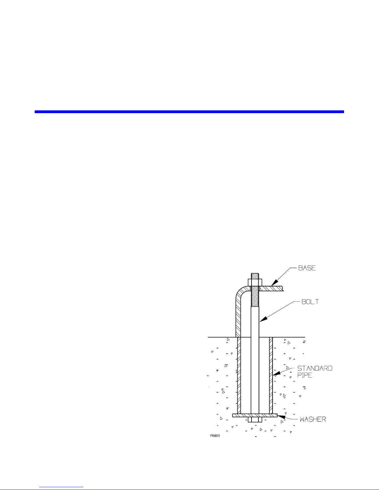
MOUNTING THE COMPRESSOR UNIT
A solid foundation reduces noise and vibration, and will
improve compressor performance. On permanent
installations it is recommended the compressor be secured
by anchor bolts as shown. This arrangement allows for
slight shifting of position to accommodate alignment with the
mounting holes in the base plate.
For new foundations, it is suggested that the anchor bolts
be set in concrete. When compressors are to be located on
existing concrete floors, holes should be drilled into the
concrete to hold the anchor bolts.
NOTE: To keep vibration at a minimum, in addition to a
solid concrete foundation it is important that the concrete be
located on a stable soil foundation. The base should have
complete contact along its entire length with the foundation.
Visible separations can result in vibrations which are
magnified in the upper part of the unit.
Pipe Type Anchor Bolt-Box
CB9A-020 page 7
Page 8

OPERATION
PRE-STARTUP CHECK LIST
1. After the compressor is installed in the system, a complete leak test should be performed on both the
compressor and the piping.
2. Check the alignment of the pipes to the compressor. Pipes should be supported so that they do not spring
away or drop down when flanges or union joints are disconnected.
3. If V-belt driven, check the alignment of the motor and the compressor sheaves. The faces of the sheaves
must be parallel.
4. It is recommended that pressure gauges be installed in the discharge and inlet lines. These can be used
to check actual suction and discharge conditions after startup.
5. Check the electrical connections for proper wiring, grounding, etc.
6. Blackmer compressors are shipped from the factory without oil in the crankcase. Fill with a high quality oil
of the proper viscosity (see "Lubrication").
7. Disconnect the power and remove the nameplate. Squirt oil onto the crosshead guide bores and rotate
the compressor by hand to verify smooth operation.
8. Ensure that all guards are in place.
STARTUP PROCEDURE
1. Start the compressor and check for oil pressure within 30 seconds. The pressure should register 25 psig
(172 kPa). Adjust if necessary (see "Lubrication"). If proper oil pressure is not present, stop the
compressor and correct the problem. Operating the compressor with low oil pressure will cause severe
damage to the unit. Note: These models must operate with the proper rotation direction. See 'Rotation'
section.
2. Verify the suction and discharge pressures to ensure that all readings are within the expected ranges.
Operating limits listed in the "Compressor Data" section must not be exceeded
3. Check for leakage from the piping and equipment.
4. If the seals (packing) have just been replaced, the lower seal must be manually lubricated during the first
60 minutes of operation. See "Packing Lubrication" section. New compressors have had the packing
broken in at the factory.
5. On newly rebuilt units, the valve holddown screws, valve cover plate bolts and cylinder head bolts should
all be retightened after 60 minutes running time. Also retighten all holddown bolts, flywheel bolts, etc. after
60 minutes running time.
CB9A-020 page 8
Page 9
MAINTENANCE
MAINTENANCE AND TROUBLESHOOTING MUST BE DONE BY AN INDIVIDUAL EXPERIENCED WITH
COMPRESSOR MAINTENANCE AND THE TYPE OF SYSTEM INVOLVED.
CAUTION: Before work is started on the compressor make sure all pressure is bled off on both the
suction and discharge.
NOTE: When servicing the compressor, refer to the appropriate Parts Lists for detailed exploded views of the
compressor parts.
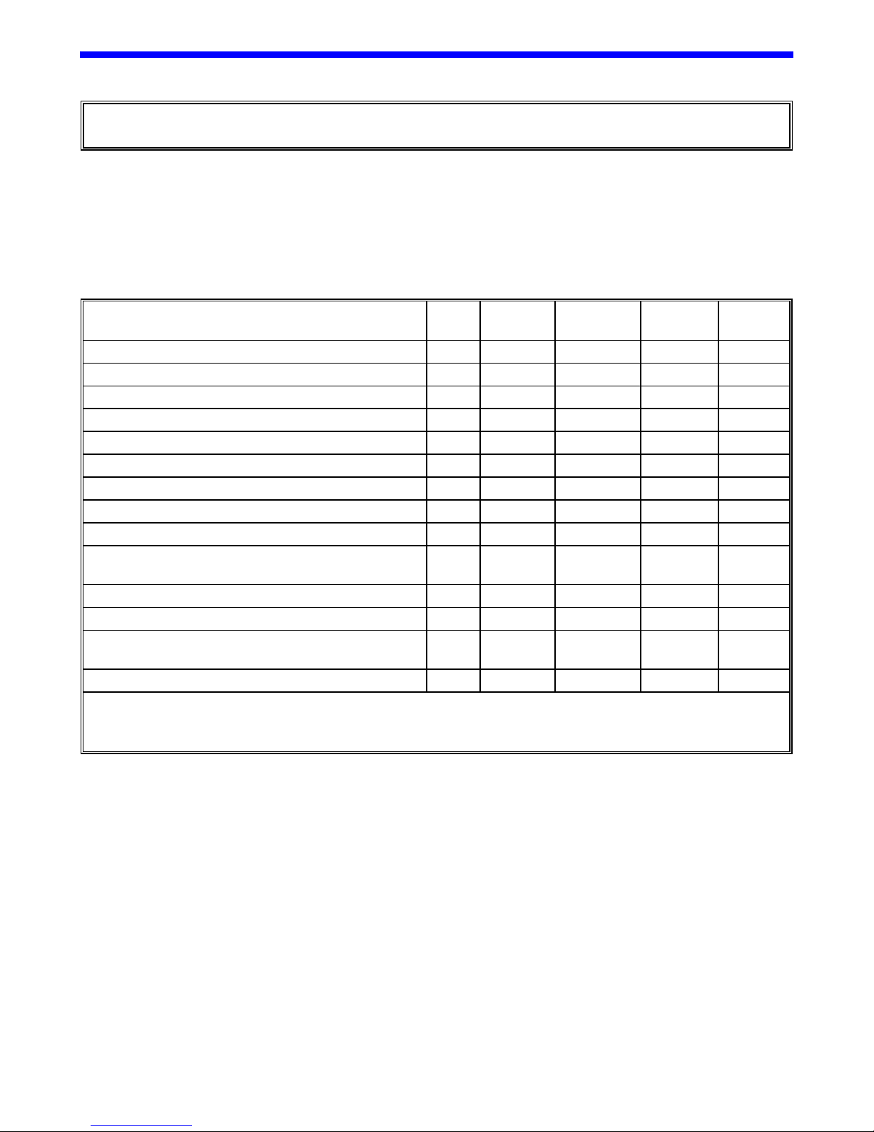
ROUTINE SERVICE SCHEDULE
Daily Weekly Monthly
Overall Visual Check X
Check Crankcase Oil Pressure X
Check Suction Pressure X
Check Discharge Pressure X
Drain Distance Piece X
Drain Liquid From Accumulation Points X
Clean Compressor Cooling Fins X
Check Crankcase Oil Level * X*
Check V-Belt Tension X
Change Oil *
(and Optional External Oil Filter)
Check Inlet Filter/Strainer Element X
Inspect Valves X
Lubricate Motor Bearings per Manufacturers
Suggestions
Inspect Motor Starter Contact Points X
X*
X
6
Months Yearly
* Change oil every 1,000 hours of operation (2,000 hours with optional external oil filter), or every 6
months which ever occurs first. If the oil becomes unusually dirty, change oil and external filter as
often as needed to maintain clean oil.
CB9A-020 page 9
Page 10
MAINTENANCE
TOOL LIST
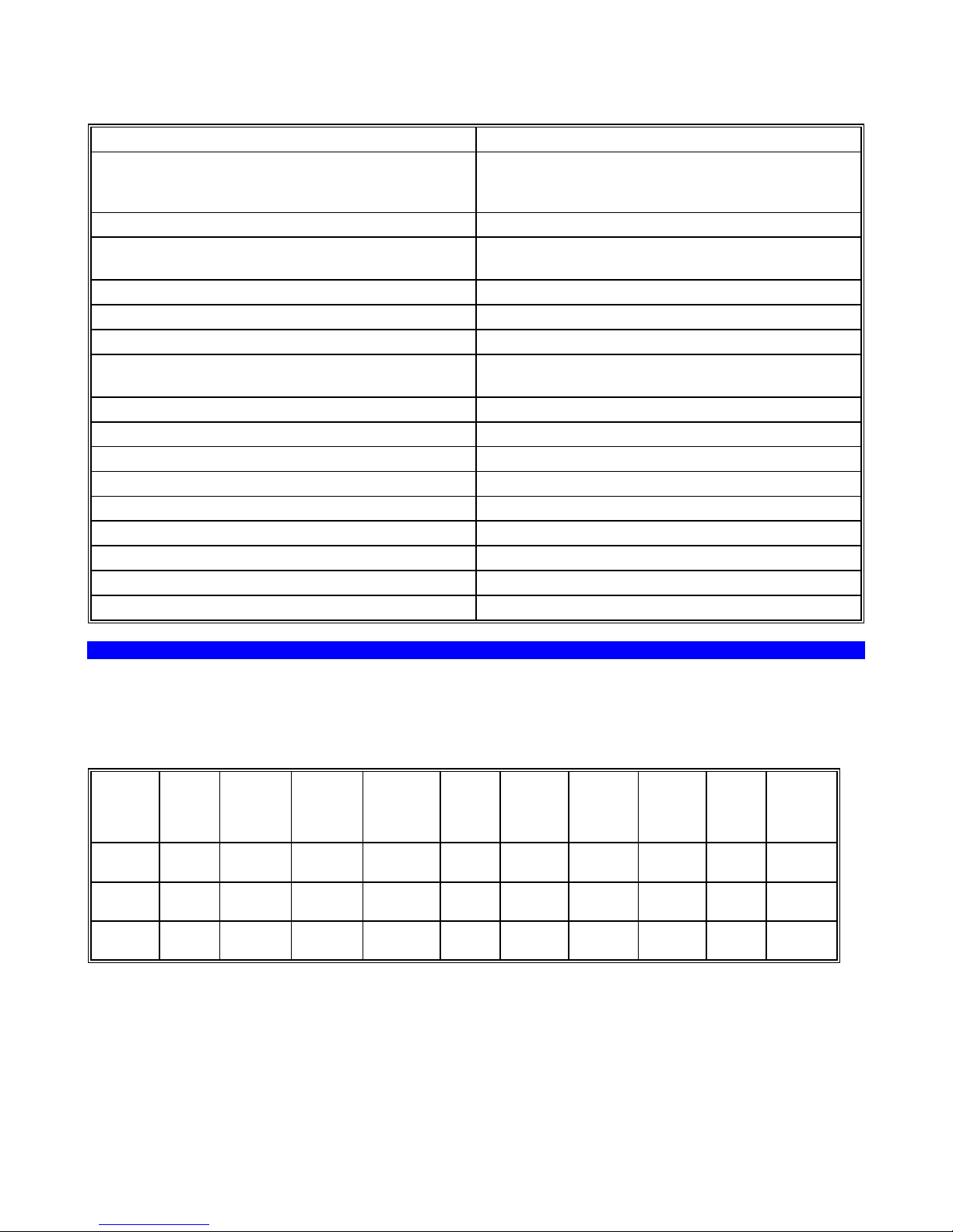
Description Used For:
Blackmer Packing Installation Tool
790536 for 160, 340, & 360 series
790538 for 600 series compressors
Blackmer Wrench 790535 Valve Hold-down screw
3" Adjustable Spanner with 1/4" pins
(like Blackmer PN 790316)
9/16, 5/8 or 3/4" End Wrench Cylinder and Crosshead Guide
1-1/16" Wrench or Socket Valve Caps
3/16" Allen Wrench
7/16", 1/2", 9/16", 3/4", 5/8", 3/4",
7/8" & 1-3/8" Sockets
Internal Snap Ring Pliers Seal Replacement
Feeler gauges or Depth Micrometer Piston Clearance
Screwdriver, Flat Blade Nameplate screws, Packing Installation
Pliers
Rubber Mallet
Arbor Press Wrist Pin Removal
Bearing Puller Crankshaft Bearin gs
Torque Wrench, 0 to 45 ft-lb range Various
Hoist (useful) Cylinder and Crosshead Guide
BOLT TORQUES
Proper bolt torques to use when reassembling the compressor.
BOLT TORQUE FOR BLACKMER COMPRESSORS FT-LBS (Nm)
Size
160
360
600
Con.
Rod
Bolt
30
(40.7)
35
(47.5)
45
(61.0
Bearing
Carrier
30
(40.7)
30
(40.7)
30
(40.7)
Bearing
Cover
Plate
35
(47.5)
35
(47.5)
40
(54.2)
Crank
Case
Inspec.
Plate
7
(9.5)
7
(9.5)
7
(9.5)
Rod-packing protection during installation.
Piston Nut, Piston,
Packing Box Hold-down Ring
Various
Cross
Head
Guide
(33.9)
(47.5)
(54.2)
Cylinder Head Valve
25
35
40
25
(33.9)
35
(47.5)
40
(54.2)
20
(27.1)
40
(54.2)
40
(54.2)
Assy.
Nut
-- -- 40
10
(13.6)
10
(13.6)
Valve
Cover
Plate
35
(47.5)
35
(47.5)
Valve
Hold
Down
Screw
(54.2)
40
(54.2)
40
(54.2)
CB9A-020 page 10
Page 11
MAINTENANCE
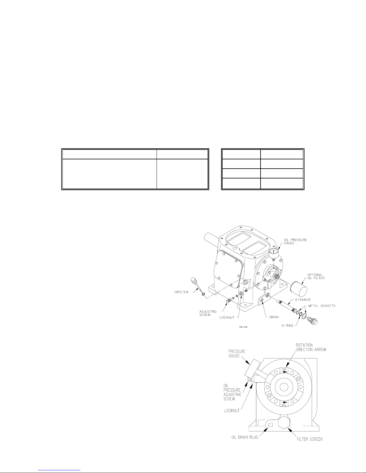
CRANKCASE LUBRICATION
Non-detergent motor oils are recommended. However, detergent oils can be used providing the gas being
handled does not react with the detergent in the oil. If using a detergent oil, be sure there is not a compatibility
problem. The following gasses are known to react with detergents in oil:
Ammonia Monoethylamine
Monomethylamine Dimethylamine Trimethylamine
The oil used, detergent or non-detergent, should be of high quality such as API grade SF, SG, SH or
similar. API grade SA, SB, SC or similar oils should never be used. Recycled oils should never be
used.
The oil in the crankcase should be changed every 1,000 hours or 180 days, whichever is shorter. Under severe
dusty or sandy operating conditions, the oil should be changed every 500 hours or every 90 days. NOTE: When
equipped with a spin-on oil filter, intervals between oil changes may double (not to exceed 180 days).
Air Temperature Oil Viscosity Size # Quarts
Below 0°F (-18°C)
0 to 32°F (-18 to 0°C)
32 to 80°F (0 to 27°C)
80°F (27°C) and above
To change the oil, drain the crankcase then clean the oil pickup screen in a suitable solvent. When reinstalling
the pickup screen, inspect the metal gasket and the O-ring for damage. Replace if necessary. If supplied, the
external oil filter should also be replaced. Refill the crankcase via the dipstick opening.
SAE 5W
SAE 10W
SAE 20W
SAE 30W
SETTING THE OIL PRESSURE: The oil
pressure should be about 25 psig.
1. Loosen the locknut.
2. To increase the pressure setting turn the
adjusting screw inward (clockwise).
To decrease the pressure setting turn the
adjusting screw outward (counterclockwise).
3. Retighten the locknut.
ROTATION
The compressor rotation direction is indicated by the upper arrow
(12 o'clock position) located on the face of the oil pump cover.
To reverse the rotation of the compressor, remove the capscrews in
the oil pump cover and rotate the cover 180 degrees. In this
position, the upper arrow on the oil pump cover will indicate rotation
in the opposite direction. NOTE: The oil pump pressure gauge must
also be removed and reinstalled in the upper gauge port.
OIL CAPACITY
160A 2
360A 3
600A 6
CB9A-020 page 11
Page 12

MAINTENANCE
COMPRESSOR DISASSEMBLY
CAUTION: Before work is started on the compressor make sure all pressure is bled off on both the
suction and discharge.
1. Remove the center head capscrews from the cylinder head. Remove the outer cylinder head capscrews.
2. The cylinder head assembly and cylinder head O-rings can now be removed from the cylinder. The
suction and discharge valve assemblies will come off with the cylinder head. For valve disassembly
instructions refer to "Valve Replacement."
3. Removal of the piston requires a 3" adjustable spanner wrench with 1/4" pins (such as Blackmer PN
790316)
a. Rotate the flywheel by hand to bring a piston to top dead center of the cylinder.
b. Remove the piston nut by rotating the nut counterclockwise. (Note the nylon locking insert in the
piston nut. This insert must be replaced during reassembly.)
c. To remove the piston from the cylinder, rotate it counterclockwise with the use of the adjustable
spanner wrench. For removal and replacement of the piston rings, refer to "Piston Ring
Replacement."
d. Remove the thrust washer and shims. Keep the shims & piston together.
e. Repeat these steps for the other piston.
4. Remove the cylinder capscrews. The cylinder and cylinder O-rings can then be lifted from the crosshead
guide (or distance piece).
5. Removal of the packing boxes is dependent on the Model Number of the Compressor. For disassembly of
the packing boxes, refer to "Seal (Packing) Replacement".
Single-Seal Models (HD161, HD361, HD601)
a. Using an adjustable spanner wrench, remove the packing box hold-down rings. (Replace the nylon
locking inserts in the hold-down rings during reassembly.)
b. Remove the packing boxes and packing box O-rings from the piston rods.
Double-Seal Model (HD162)
a. Lift the upper packing box asssemblies and O-rings off the piston rods.
b. Remove the oil diflector ring off each piston rod.
c. Remove the distance piece capscrews and lift the distance piece and O-rings off the crosshead
guide.
d. Lift the lower packing box asseblies and O-rings off the piston rods.
Double-Seal Models (HD362, HD602)
a. Using an adjustable spanner wrench, remove the packing box hold-down rings. (Replace the nylon
locking inserts in the hold-down rings during reassembly.)
b. The spacer rings, upper packing box O-rings, packing boxes and lower packing box O-rings can
then be removed from the piston rods.
Triple-Seal Models (HD163, HD363, HD603)
a. Lift the upper packing box assemblies and O-rings off the piston rods.
b. Remove the upper distance piece capscrews and lift the upper distance piece and O-rings off the
crosshead guide.
c. Using an adjustable spanner wrench, remove the packing box hold-down rings. (Replace the nylon
locking inserts in the hold-down rings during reassembly.)
d. The spacer rings, upper packing box O-rings, packing boxes and lower packing box O-rings can
then be removed from the piston rods.
6. Remove the crosshead guide capscrews, and lift the crosshead guide and gasket from the crankcase.
7. To remove the connecting rod assemblies (with the crossheads attached) it may be necessary to drain the
oil from the crankcase. NOTE: The piston rod is permanently attached to the crosshead to form a single
assembly. Do not attempt disassembly.
a. Remove the inspection plate from the crankcase.
b. Remove the locknuts from the connecting rod bolts. This will release the connecting rod cap (the
lower half of the connecting rod) and the two halves of the bearing insert. NOTE: The connecting
rod and the connecting rod cap are marked with a dot on one side so that they can be matched
properly when reassembling.
CB9A-020 page 12
Page 13

MAINTENANCE
c. Lift the crosshead assembly and connecting rod off the top of the crankcase.
NOTE: The connecting rod parts are not interchangeable and must be reassembled with the
same upper and lower halves. To avoid confusion, it is advisable to work on one connecting
rod at a time, or to mark the individual halves with corresponding numbers.
d. Remove the opposite connecting rod and crosshead assembly in the same manner as outlined in
step 8.
8. Rest the crosshead assembly on a bench. Carefully drive the wrist pin and wrist pin plugs out of the
crosshead and connecting rod using a suitable pin driver or an arbor press. Removal of the pin releases
the crosshead assembly from the connecting rod.
9. If necessary, the wrist pin bushings can be replaced after the crossheads are removed. Connecting Rods
with new brass bushings must be honed to the proper size after inst allation.
Inner Dimensions: 0.8753" to 0.8756" (22.233 mm to 22.240 mm).
10. To replace the crankshaft bearings, the crankcase must be disassembled, and the crankshaft removed.
Refer to "Bearing Replacement" for disassembly instructions.
COMPRESSOR ASSEMBLY
Compressor assembly is generally the opposite of compressor disassembly. Before reassembling, clean each
part thoroughly. Check all machined surfaces for burrs or roughness, and file lightly if necessary.
NOTE: If any of the O-rings or gaskets are removed or disturbed during service, it is recommended they be
replaced with new.
1. CRANKCASE ASSEMBLY
After replacing the crankshaft, bearing carrier, and bearing carrier assembly (see "Bearing Replacement"),
the connecting rod and crosshead can be installed.
a. Coat the wrist pin, the wrist pin bore in the crosshead assembly, and the bushing in the connecting rod
with grease, then attach the connecting rod to the crosshead assembly.
b. Start the wrist pin in the bore of the crosshead assembly and tap lightly until the pin begins to project
through to the inside of the crosshead assembly.
c. Slide the connecting rod up inside of the crosshead assembly and align the bushing with the wrist pin.
d. Lightly tap the wrist pin through the connecting rod until it is centered in the crosshead assembly.
NOTE: The wrist pin should be snug in the crosshead assembly. The connecting rod should rotate
freely on the wrist pin, but should not be loose.
e. Dip the wrist pin plugs in grease and press them in place.
f. Place the bearing halves into each half of the connecting rod, aligning the bearing tangs with the slots
in the connecting rod. Coat the bearing with grease.
g. Set the top of the connecting rod over the crankshaft journal. Replace the connecting rod cap,
remembering that the dots on the connecting rod and cap must be on the same side.
h. Start the nuts on the connecting rod bolts and torque per the Bolt Torque Table.
i. Follow this same procedure for the opposite connecting rod.
2. CROSSHEAD GUIDE
a. Place the crosshead guide gasket on top of the crankcase.
b. Lubricate the inside bore of the crosshead guide with light oil.
c. Set the crosshead guide over the piston rods and the crossheads, and slowly lower it against the
crankcase. Make certain that the crosshead assemblies are started straight in the bores of the
crosshead guide to prevent binding when lowering the crosshead guide into position.
d. Install the crosshead guide capscrews loosely.
3. Fill the crankcase with oil. See "Lubrication" for proper amount. Squirt oil into the crankshaft, roller
bearings, crankshaft journals, and crosshead assemblies so they will have lubrication at start up.
4. Attach the inspection plate and the inspection plate gasket to the crankcase.
CB9A-020 page 13
Page 14

MAINTENANCE
5. PACKING BOX ASSEMBLIES
Before installing the packing boxes into the crosshead guide, inspect the piston rods for scoring or
roughness. Remove any burrs or sharp edges. Lubricate the piston rods and packing box O-rings with
light oil. Do not damage the packing when starting it over the rod. Use of a Blackmer packing
installation tool is recommended.
Single-Seal Models (HD161, HD361, HD601)
a. Insert the packing box O-ring into the crosshead guide.
b. Start the packing box assembly, short end down, over the piston rod and into the counter-bored hole of
the crosshead guide.
c. Install the packing box retainer ring with new nylon locking inserts, and tighten securely.
d. Repeat the above steps for the remaining packing box.
Double-Seal Model (HD162)
a. Insert the lower packing box O-ring into the crosshead guide.
b. Install the packing box assembly over the piston rod and into the counter-bored hole of the crosshead
guide.
c. Repeat steps a - b for the other lower packing box.
d. Install new O-rings in the bottom of the distance piece. A small amount of grease may be used to hold
the O-rings in place during assembly.
e. Set the distance piece over the piston rods and against the crosshead guide, install and tighten the
upper distance piece capscrews.
f. Install each upper packing box O-ring over the piston rods.
g. Install each upper packing box over the piston rods.
Double-Seal Models (HD362, HD602)
a. Insert the lower packing box O-ring into the crosshead guide.
b. Start the packing box assembly, short end down, over the piston rod.
c. After the lower set of packing is started over the piston rod, make sure the oil deflector ring is properly
aligned (with the flat side down) over the piston rod. Use the hole in the side of the packing box to
center the deflector ring. Once the deflector ring is over the rod, the packing box can be fully inserted.
d. Install the upper packing box O-ring on the end of the packing box.
e. Place the packing box spacer ring over the O-ring.
f. Install the packing box retainer ring with new nylon locking inserts, and tighten.
g. Repeat the above steps for the remaining packing box.
Triple-Seal Models (HD163, HD363, HD603)
a. Follow the instructions for the Double-seal model.
b. Install new O-rings in the bottom of the upper distance piece. A small amount of grease may be used
to hold the O-rings in place during assembly.
c. Set the upper distance piece over the piston rods and against the crosshead guide, loosely install
upper distance piece capscrews.
d. Install each upper packing box O-ring over the piston rods.
e. Install each upper packing box over the piston rods.
6. Rotate the crankshaft by hand a few times, then uniformly tighten the crosshead guide capscrews (and
upper distance piece capscrews on triple-seal models) per the Bolt Torque Table.
7. New packing must be broken in. Refer to the end of "Seal Replacement".
8. CYLINDER ASSEMBLY
a. Install new O-rings in the bottom of the cylinder. A small amount of grease may be used to hold the
O-rings in place during assembly.
b. Set the cylinder over the piston rods and against the crosshead guide.
c. Loosely install the cylinder capscrews.
9. Rotate the flywheel by hand to ensure the compressor turns freely.
CB9A-020 page 14
Page 15
MAINTENANCE
10. PISTONS
a. If necessary, replace the piston rings and piston ring expanders (see "Piston Ring Replacement").
b. Rotate the flywheel by hand to bring one piston rod to top dead center of the cylinder assembly.
c. Set one (1) thrust washer and one (1) shim down against the shoulder of the piston rod.
d. Squeeze the piston rings inward, with light pressure, while threading the piston clockwise onto the rod.
Tighten with the 3" adjustable spanner wrench.
e. Follow this same procedure for the second piston.
f. Rotate the compressor by hand a number of times to verify that the pistons are centered in the cylinder
bores. The pistons must not touch the cylinder walls. If necessary, adjust the cylinder.
g. Tighten the cylinder capscrews per the Bolt Torque Table in an alternating pattern.
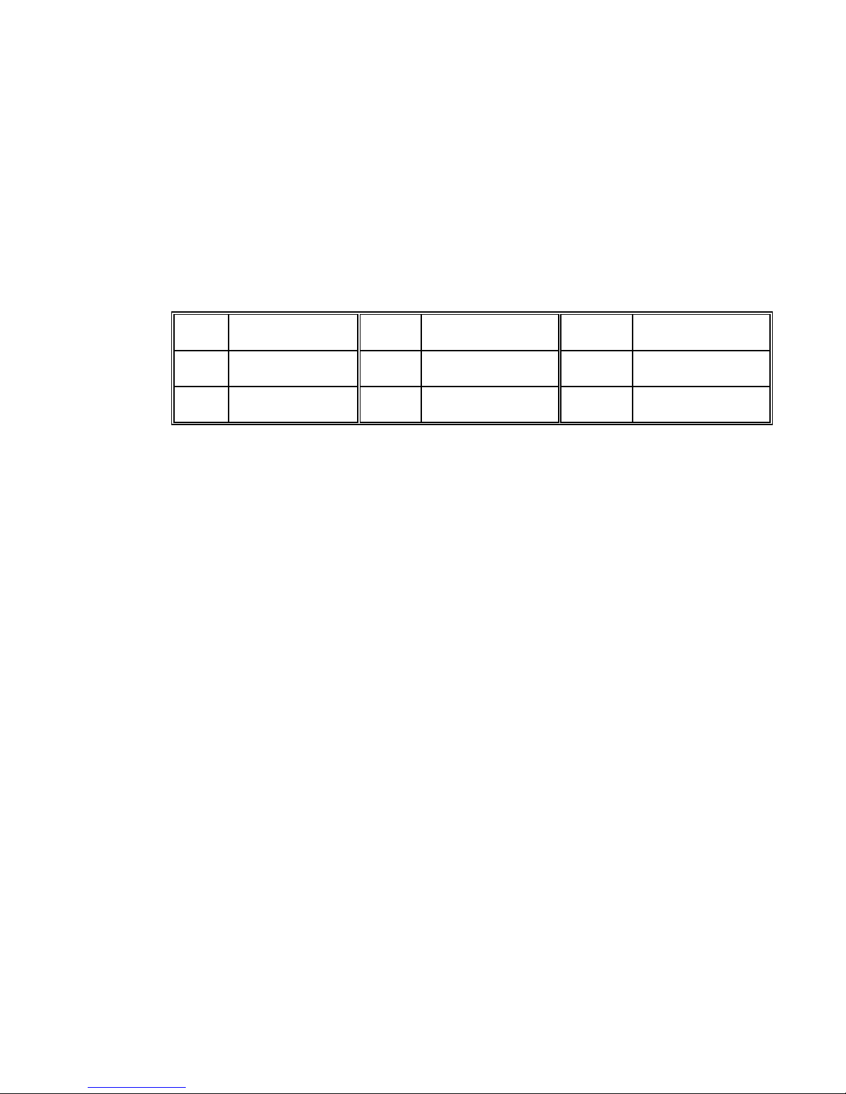
h. It is important that the proper number of shims be installed under the piston. To check, rotate the
flywheel by hand to bring one piston to the top.
1. Measure the distance from the top of the piston to the top of the cylinder.
HD161 .010" to .025"
(.254 to .635 mm
HD162 .015" to .030"
(.381 to .762 mm)
HD163 .025" to .040"
(.635 to 1.016 mm)
2. If necessary, remove the piston and add or subtract shims accordingly.
3. Follow this same procedure for the second piston.
i. Replace the nylon locking inserts in the piston retainer nuts.
j. Thread the piston nuts onto the piston rods and tighten with the spanner wrench.
11. CYLINDER HEAD ASSEMBLY
If the valve assemblies have been removed from the cylinder head, it is easiest to reinstall them before
attaching the cylinder head to the cylinder assembly. Refer to "Valve Replacement" for instructions.
a. Place the cylinder head O-rings in the grooves located on top of the cylinder.
b. Place the cylinder head assembly on top of the cylinder.
c. Hand tighten the outer capscrews and center capscrews into the cylinder head.
Note: Gaskets are used on the HD160 series center capscrews.
d. Uniformly torque the cylinder head capscrews according to the Bolt Torque Table.
12. Rotate the compressor by hand to verify that it turns freely. Make sure the pistons are not hitting against
the bottom of the cylinder head assembly.
13. Refer to the "Pre-Startup Check List", and "Startup Procedure".
14. After the compressor has been run for a sufficient enough time to reach operating temperature, allow to
cool and retighten the valve hold down screws.
HD361 .020" to .035"
(.508 to .889 mm)
HD362 .025" to .040"
(.635 to 1.016 mm)
HD363 .050" to .065"
(1.270 to 1.651 mm)
HD601
HDL601
HD602
HDL602
HD603
HDL603
.020" to .035"
(.508 to .889 mm)
.030" to .045"
(.762 to 1.143 mm)
.060" to .075"
(1.524 to 1.905 mm)
CB9A-020 page 15
Page 16
MAINTENANCE
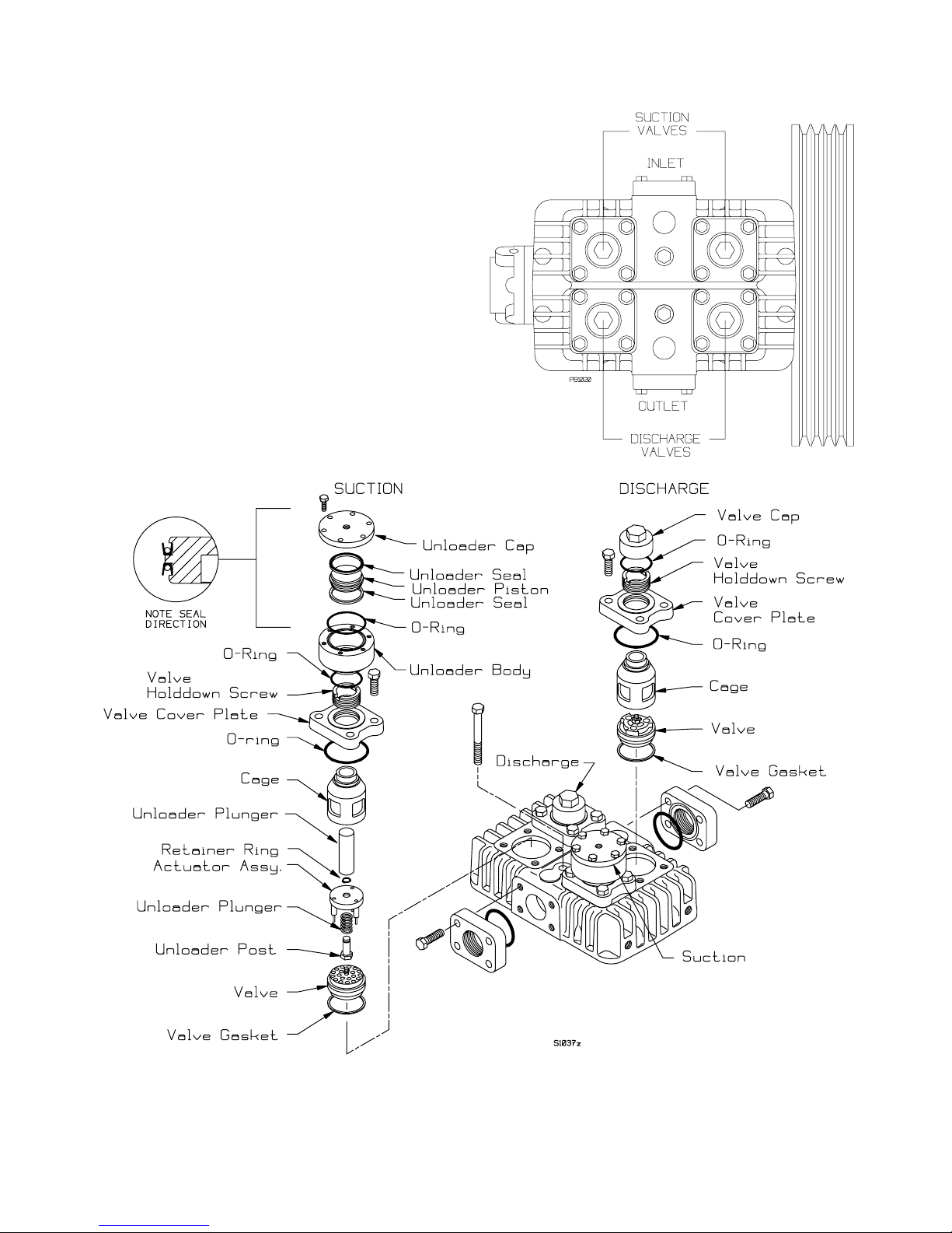
VALVE REPLACEMENT
When replacing the valves, it is important to install
the suction and discharge valves in the correct
location in the cylinder head.
NOTE: The valves may be removed without
removing the cylinder head from the cylinder. Be
sure to remove and replace the valve gaskets.
Typical Head Assembly (with Suction Valve Unloaders).
CB9A-020 page 16
Page 17
MAINTENANCE
VALVE REPLACEMENT continued
1. Remove the valve cap (or unloader assembly) and O-ring from each valve.
2. Remove the valve hold down screw with a spanner wrench (such as Blackmer PN 790535 ).
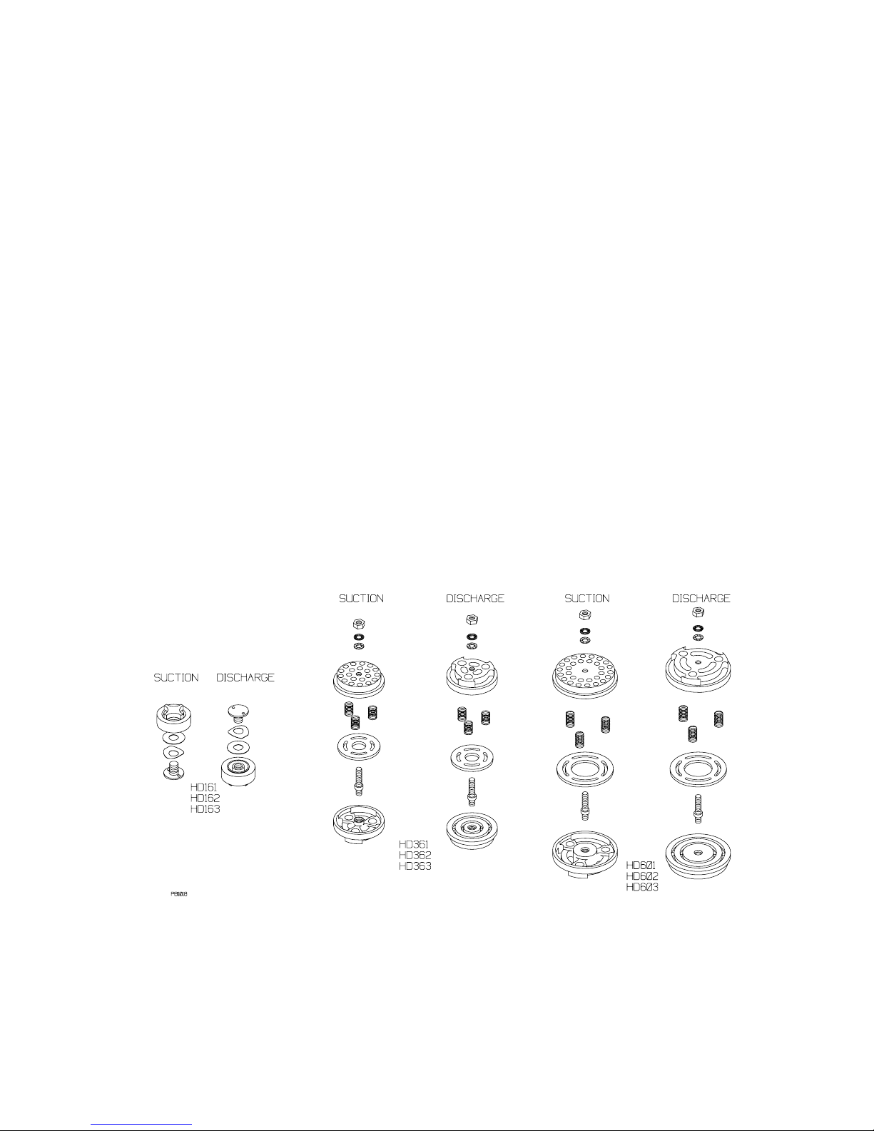
3. Valve Removal and Disassembly
Models HD161, HD162 & HD163
a. Remove the valve cage (and unloader plunger, actuator, and spring).
b. Remove the valve assembly and the valve gasket.
c. Inspect the valve for wear or breakage.
d. Valve Repair
1 Unscrew the valve halves and remove the spring and plate.
2 Inspect and replace worn components.
3 Reassemble valves as shown below and tighten the valve halves together.
Models HD361, HD362, HD363, HD601, HD602 & HD603
a. Remove the valve cover plate capscrews then lift off the cover plate and O-ring.
b. Remove the valve cage (and unloader plunger).
c. Remove the valve assembly and the valve gasket.
d. Inspect the valve for wear or breakage.
e. Valve Repair
1 Remove hex nut from valve (after removing the unloader actuator retaining ring, the actuator, spring,
and post.)
2 Separate the valve halves and remove springs and plate.
3 Inspect and replace worn components.
4 Reassemble valves as shown in the drawing and tighten the valve assembly nut according to the
Bolt Torque Table.
5 (Reassem ble the unloader post, spring, actuator and retainer ring.)
Typical Valve Assemblies
CB9A-020 page 17
Page 18

MAINTENANCE
4. To reinstall valves:
a. Install a new valve gasket into the cylinder head (remove any old gaskets).
b. Install the valve assembly in the cylinder head. Make sure the valve's orientation and location are
correct.
c. Center the valve cage on the valve assembly.
d. Applies only to suction valves with unloaders.
Models HD161, HD162 & HD163:
Install the Unloader spring, actuator and plunger in the cage.
Models HD361, HD362, HD363, HD601, HD602 & HD603
Install the unloader plunger in the cage.
e. Models HD361, HD362, HD363, HD601, HD602 & HD603
Make sure the valve hold down screw is removed from the cover plate, then install the valve cover plate
with a new O-ring. Tighten the cover plate capscrews according to the Bolt Torque Table.
f. Install the hold down screw and tighten according to the Bolt Torque Table.
g. Install the valve cap (or unloader assembly) and O-ring. (A little oil or grease on the O-ring will help
hold it in place during installation.)
5. After replacing the valves, rotate the flywheel by hand to check for interference between the pistons and the
valves.
6. After 60 minutes of running time, remove the valve cap (or unloader assembly) and retorque the hold down
screw. Replace the valve cap and O-ring.
UNLOADER SEAL REPLACEMENT
a. Remove the unloader cap and O-ring.
b. Remove the unloader body from the cylinder head (a strap wrench is helpful).
c. Push the unloader piston out the top of the unloader body.
d. Inspect and replace the seals as needed - note the seal orientation!
e. Inspect the unloader body bore - it must be clean and smooth.
f. Reassemble in the reverse order.
PISTON RING REPLACEMENT
1. Follow steps 1 through 3 of "Compressor Disassembly."
2. Remove the piston rings and the piston ring expanders from the pistons.
3. To replace the piston rings:
a. Place an expander in the top groove of the piston. Place an expander in the second groove with the
break in this expander 180 degrees from the break of the top expander. Place the third expander in the
bottom groove with its break in the same position as the top expander.
b. Place piston rings in all three grooves of the piston. Make sure the breaks in the piston rings are
directly opposite the breaks in the corresponding expanders.
4. Reassemble the compressor per steps 10 through 14 of "Compressor Assembly."
CB9A-020 page 18
Page 19
MAINTENANCE
SEAL (PACKING) REPLACEMENT
1. Follow the "Compressor Disassembly" section to remove the packing boxes.
2. Remove the upper and lower retainer ring from the packing box being serviced. Disassemble the packing
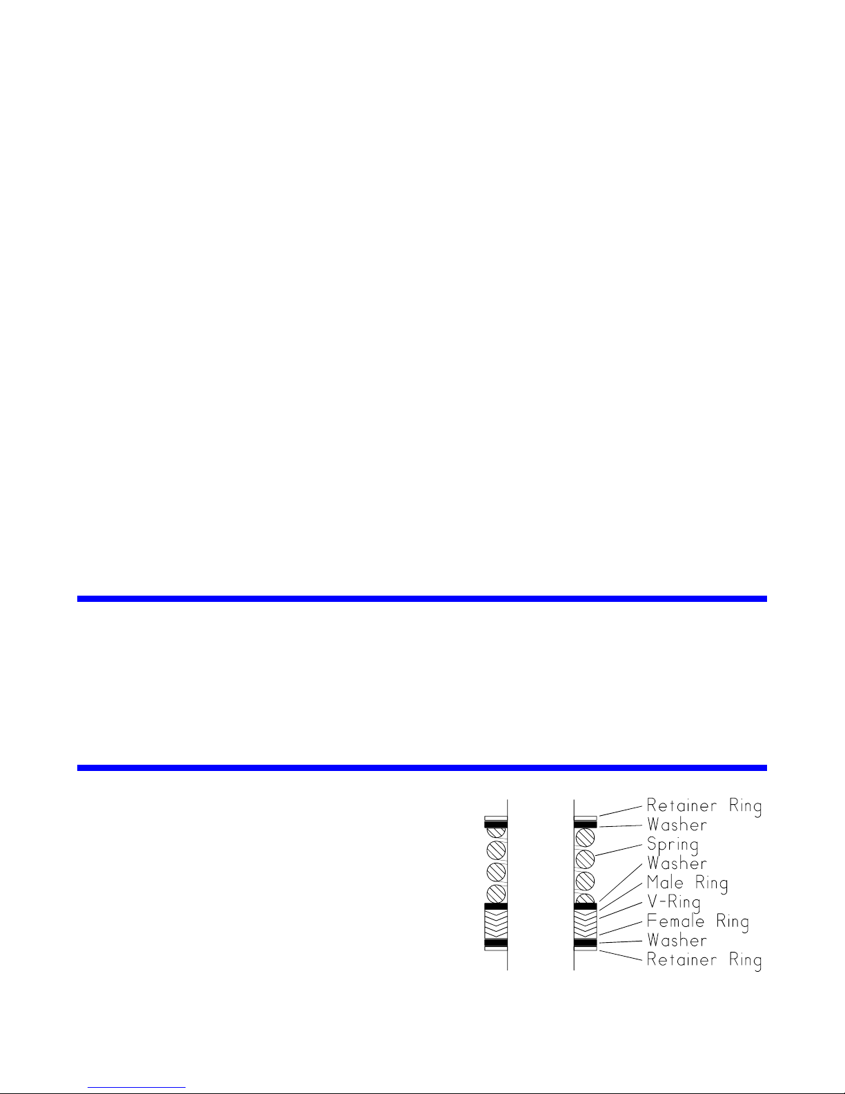
box and discard the old packing sets and packing springs.
NOTE: Before reassembling the packing boxes, refer back to "Seal Arrangements". The 6
th
digit of the
Compressor ID# identifies the packing orientation.
CB9A-020 page 19
Page 20

MAINTENANCE
3. Packing boxes may contain either one or two sets of packing, depending on the compressor being
serviced. To reassemble a packing box:
a. Clean the packing box in a suitable solvent. Inspect the bore for wear, roughness, or corrosion.
b. Install the first retainer ring (start with the inner ring on two seal packing boxes). See "Seal
Arrangements" for the proper location and orientation of the packing components, then install the
packing rings, spring, washers, and the second retainer ring. Note: To ease installation on the
second retainer ring, use a screwdriver handle and press on the last washer to compress the seal
spring slightly.
c. Two seal packing boxes only
Insert the oil deflector ring through the top of the packing box, flat side down, into the cavity between
the upper and lower packing. NOTE: The oil deflector ring will be positioned between the two sets of
packing. Install the second set of packing per step b.
4. The lower packing must be manually lubricated with oil several times during the first 60 minutes of
compressor operation. This will prevent overheating of the piston rods and potential damage to the
packing material.
WARNING!
DO NOT INSERT OBJECTS OR FINGERS INTO INSPECTION CAVITY
WHILE COMPRESSOR IS OPERATING.
To lubricate the packing:
Remove the inspection plate from the crosshead guide.
Stop the compressor frequently (approximately every 5 minutes) to allow adequate cooling of the
piston rods.
Lubricate the piston rods each time the compressor is stopped. A small oil can should be used for
lubrication.
5. Proceed according to steps 5 through 14 of "Compressor Assembly."
CB9A-020 page 20
Page 21
MAINTENANCE
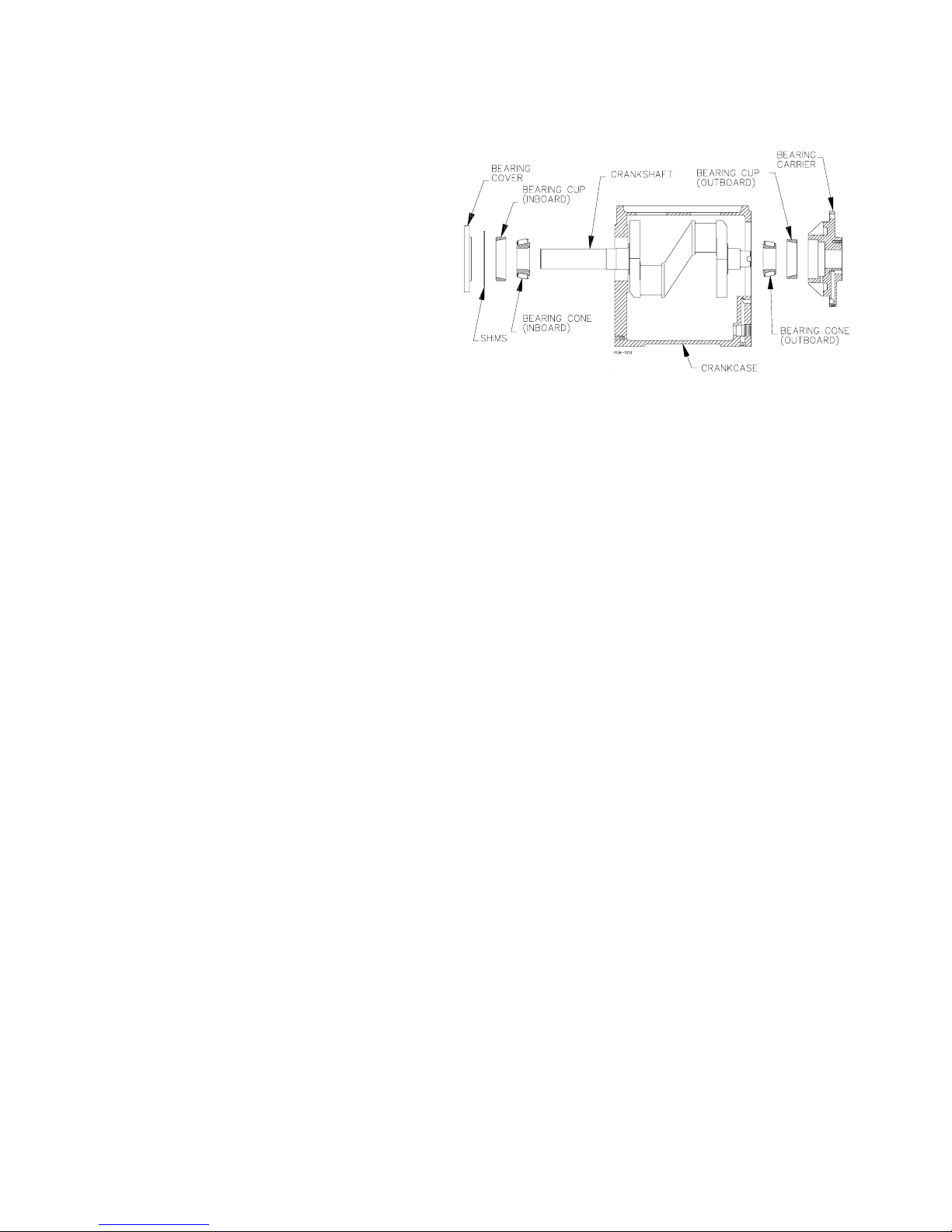
BEARING REPLACEMENT
NOTE: When replacing the bearings, the entire
bearing assembly, including the bearing cup and
the bearing cone, must be replaced.
1. Follow the steps in "Compressor
Disassembly."
2. Remove the Oil Pump per the section on "Oil
Pump Replacement".
3. Remove the flywheel.
4. Remove the bearing carrier and gasket from
the outboard end of the crankcase. The
outboard bearing cup will come off with the
bearing carrier and will need to be removed
with a bearing removal tool.
5. Remove the key from the crankshaft and slide the crankshaft through the outboard end of the crankcase.
Once the crankshaft is removed from the crankcase, the bearing cones can be removed with a bearing
puller.
6. Remove the bearing cover plate from the inboard end of the crankcase. The inboard bearing cup is
pressed into the crankcase and can be removed with the use of a bearing removal tool.
7. To install the bearings:
a. Grease the outer edges of the bearing cups.
b. Refer to the drawing for the proper orientation, and carefully press the inboard bearing cup into the
crankcase until it is flush with the outer surface of the crankcase.
c. Carefully press the outboard bearing cup into the bearing carrier assembly, noting the proper
orientation.
d. Press a bearing cone onto each end of the crankshaft with the tapered end outward. The bearing race
should rest against the shoulder on the crankshaft.
e. Lubricate the bearings with grease.
8. Install the crankshaft through the outboard end of the crankcase.
9. With the oil pump assembly removed, install the bearing carrier and gasket (the bolt holes are positioned to
ensure proper orientation). Tighten the bolts evenly per the Bolt Torque Table.
10. Reinstall the inboard bearing cover plate and a trial set of shims. If the bearings have not been replaced,
use the previous shim set. If the bearings have been replaced, use a thicker trial set of shims.
11. Rotate the crankshaft by hand to verify free movement of the shaft.
NOTE: If the crankshaft is loose, with an excessive amount of end play, too many shims have been used.
Lateral crankshaft movement (end play) between the bearings should be 0.0015" to 0.0030" (0.038 to 0.076
mm). If necessary, remove shims until the end play is within tolerance.
If the crankshaft binds or will not turn, not enough shims have been used pushing the bearing cup too tight
against the bearing cone. In this case, the crankshaft must be removed from the crankcase and the
inboard bearing cup driven toward the inboard side of the crankcase. Reinstall the crankshaft and the
bearing cover plate using additional shims as required.
12. Install the oil pump per the "Oil Pump Replacement" section.
13. Reassemble the compressor according to "Compressor Assembly."
CB9A-020 page 21
Page 22
MAINTENANCE
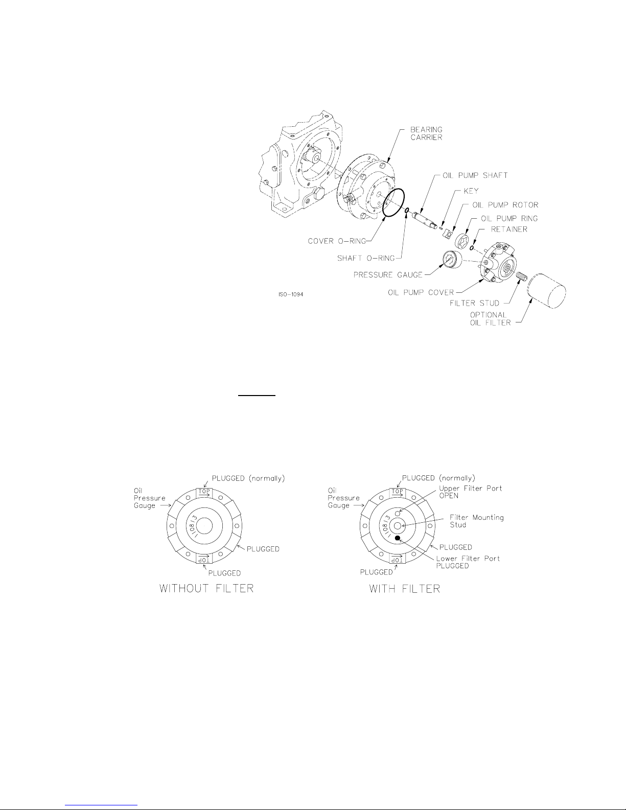
OIL PUMP REPLACEMENT
1. Remove the oil pump cover bolts and the oil pump cover.
2. Remove the cover O-ring, oil pump
ring and shaft assembly.
3. Clean, inspect and replace parts as
necessary.
4. Place the oil pump shaft assembly
(complete with oil pump rotor, key,
retainer ring and new shaft O-ring)
into the bearing housing. If the
bearing housing is bolted to the
crankcase, the slot in the end of the
oil pump shaft must align with the
pin in the end of the crankshaft.
5. Place the oil pump ring over the
rotor. Place the cover O-ring into
the bearing carrier (do not place it
on the oil pump cover).
6. Orient the oil pump cover with the upper direction arrow (the one labeled 'TOP') for the proper crankshaft
rotation direction.
7. Tighten the oil pump cover bolts by hand
bearing carrier by hand, either the oil pump shaft or other parts are not properly aligned. DO NOT
USE A WRENCH AT THIS POINT AS THE OIL PUMP WILL BE DAMAGED IF INSTALLED
INCORRECTLY.
8. Once the oil pump cover is secured by hand, the bolts may be evenly tightened per the Bolt Torque Table.
. NOTE: If the pump cover cannot be drawn flush with the
9. Verify that the proper plugs are installed in the oil pump cover per the above sketches.
CB9A-020 page 22
Page 23
EXTENDED STORAGE PROCEDURES
If a compressor is not to be put into service for some time, or if a compressor is to be taken out of service for an
extended period, the following procedures should be taken.
1. Fill the crankcase with rust inhibiting oil. (New compressors are shipped from the factory without oil.)
Squirt oil on the piston rods and crossheads through the nameplate opening. Loosen the V-belts to relieve
the load on the bearings. Rotate the compressor by hand a few times to distribute the oil.
2. Plug all openings and purge the compressor with an inert gas such as nitrogen or dry air at about 50 psig
(3.5 bar-g). This may be done at the factory if requested. Leave the compressor pressurized to prevent
air or moisture from entering the unit.
NOTICE: Tag the unit with a warning that it is pressurized.
3. If a purge gas is not available, fog oil into the compressor suction while rotating the unit. Then plug all
4. Turn the flywheel by hand a few revolutions once a month to distribute the oil.
5. Store the unit under a plastic wrap on its wooden shipping base up off the ground. If the unit was boxed
6. When the compressor is to be put in service, vent the remaining purge gas and change the crankcase oil.
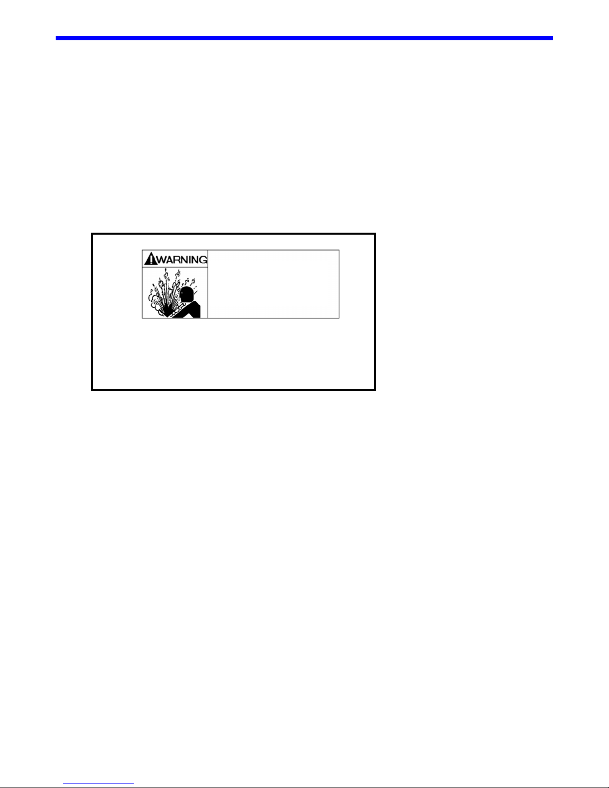
•
Hazardous pressure can
cause property damage,
serious personal injury
or death.
Compressor is pressurized with inert gas.
CAREFULLY bleed off gas BEFORE
attempting any service.
openings to keep out moisture, insects, etc.
for export shipment, leave it in its box. An indoor or covered storage area is preferable.
See the 'Pre-Startup Checklist' and 'Startup Procedure' sections in this manual.
CB9A-020 page 23
Page 24
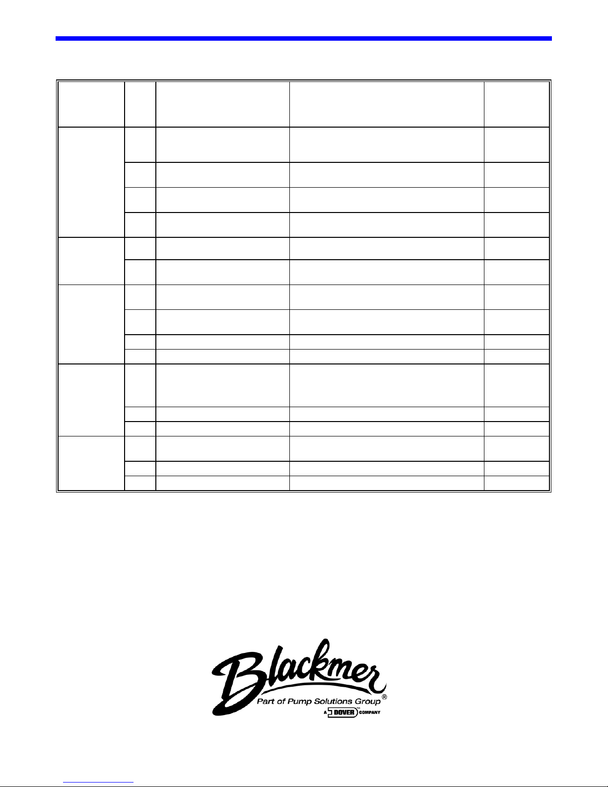
TROUBLESHOOTING
PROBLEM STEP PROBABLE CAUSE WHAT TO CHECK IF PROBLEM
STILL
EXISTS GO
TO STEP ...
Low Transfer
Rate
2 Compressor Valve Faulty Remove and inspect for broken or worn
3 Compressor Drive Slipping Tighten belts, check for sheared keys, loose
4 Piping Improperly Designed or
Knocks or
Other Noises
6 Worn Internal Parts Inspect through inspection plates and repa ir as
No Oil
Pressure
8 Oil Pump Not Working Check the Oil Pump drive tab or stop pin for
9 Low Oil Level Check and fill as necessary 10
10 Dirty Inlet Strainer Clean Inlet Strainer
Gas Leaking
From
Crankcase
Breather
12 Piston Rod Scored Replace crosshead assemblies and packing. 13
13 Improper Seal Arrangement See "Seal Arrangements".
Shake or
Vibration
15 Nonfunctioning Valves Replace or repair valves. 16
16 Unbalanced Load Consult Factory-See Notes Below
Consult factory for further information.
1 Worn or Broken Piston Rings Check condition of rings by restricting
discharge line. If pressure increases slowly,
rings are probably faulty.
springs, discs, or bodies.
couplings or flywheel.
Use proper pipe sizes.
Installed
5 Loose Valves Tighten valve hold-down screws. 6
necessary.
7 Oil Pump Relief Valve Not
Properly Set.
11 Faulty/Worn Packing Replace Packing. 12
14 Improper Mounting Ensure base rails are supported full length (see
Set oil pump relief valve. 8
damage.
"Mounting the Compressor Unit").
2
3
4
2
9
15
1809 Century Avenue, Grand Rapids, Michigan 49503 U.S.A. • (616) 241-1611 • Fax: (616) 241-3752
1108 So. Portland Avenue, Oklahoma City 73108 U.S.A. • (405) 9 42-66 22 • Fax (405) 942-2855
 Loading...