


GX
BLACKMER GX, GX2.5B, GX2B, GX4B, GX3E Operation And Maintenance
...
BLACKMER POWER PUMPS
A
INSTALLATION OPERATION AND MAINTENANCE INSTRUCTIONS
MODELS: GX2B, GX2.5B, GX3E, GX4B,
X2B, X2.5B, X3E, X4B
TABLE OF CONTENTS Page
PUMP DAT
Technical Data .................................................... 2
Initial Pump Start Up Information ........................ 2
INSTALLATION
Pre-Installation Cleaning ..................................... 3
Location and Piping ............................................. 3
Mounting ............................................................. 3
Coupling Alignment ............................................. 4
Gear Reducer Alignment – GX Models ............... 4
Pump Rotation .................................................... 4
To Change Pump Rotation .................................. 4
Check Valves ...................................................... 4
OPERATION
Pre-Start Up Check List ....................................... 5
Start Up Procedures ............................................ 5
Running the Pump in Reverse Rotation .............. 6
Flushing the Pump .............................................. 6
Pump Relief Valve ............................................... 6
Relief Valve Setting and Adjustment ................... 6
PUMP MAINTENANCE
Lubrication ............................................................. 7
Strainers ................................................................. 7
Vane Replacement ................................................. 8
Pump Disassembly ................................................ 8
Parts Replacement ................................................. 8
Pump Assembly ..................................................... 9
GEAR REDUCER MAINTENANCE
Gear Reducer Lubrication .................................... 11
Oil Seal Replacement .......................................... 12
Gear Reducer Disassembly ................................. 12
Gear Reducer Assembly ...................................... 12
PUMP TROUBLE SHOOTING .................................... 13
GEAR REDUCER TROUBLE SHOOTING .................. 14
NOTE: Numbers in parentheses following individual parts
indicate reference numbers on Blackmer Parts Lists.
Blackmer pump manuals and parts lists may be obtained
from Blackmer's website (www.blackmer.com) or by
contacting Blackmer Customer Service.
PUMP PUMP PARTS LIST
MODEL 2” 2.5” 3” 4”
GX
X
101-B01 101-B02 101-B03 101-B04
101-B05 101-B06 101-B07 101-B08
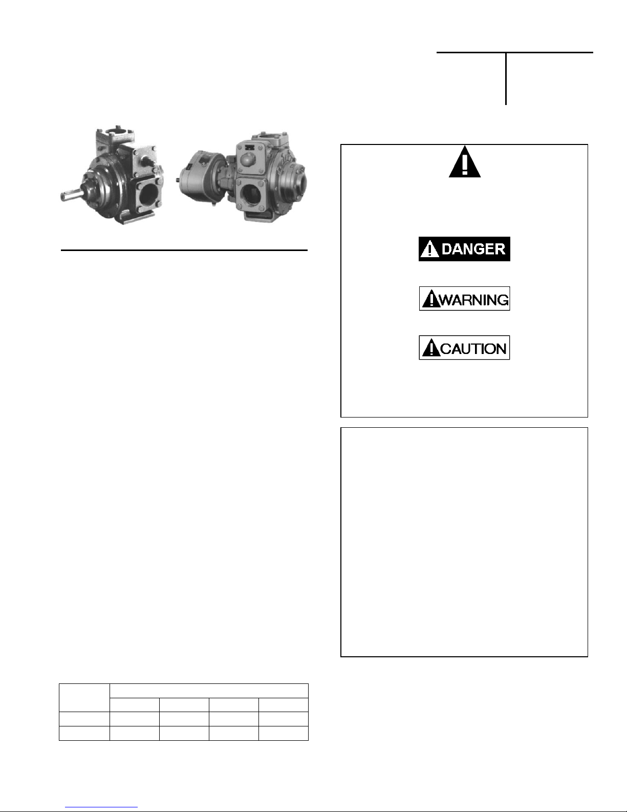
This is a SAFETY ALERT SYMBOL.
When you see this symbol on the product, or in the
manual, look for one of the following signal words and be
alert to the potential for personal injury, death or major
Warns of hazards that WILL cause serious personal injury,
death or major property damage.
Warns of hazards that CAN cause serious personal injury,
death or major property damage.
Warns of hazards that CAN cause personal injury
Indicates special instructions which are very
important and must be followed.
Blackmer Pumps MUST only be installed in systems,
which have been designed by qualified engineering
personnel. The system MUST conform to all applicable
local and national regulations and safety standards.
This manual is intended to assist in the installation and
operation of the Blackmer power pumps, and MUST be
kept with the pump.
Pump service shall be performed by qualified technician s
ONLY. Service shall conform to all applicable local and
national regulations and safety standards.
Thoroughly review this manual, all instruction s and hazard
warnings, BEFORE performing any work on the pump.
Maintain ALL system and pump operation and hazard
warning decals.
961222
INSTRUCTIONS NO. 101-B00
Section
Effective
Replaces
101
Jun 2015
Jan 2014
SAFETY DATA
property damage
or property damage.
NOTICE:
NOTICE:
SAFETY DATA
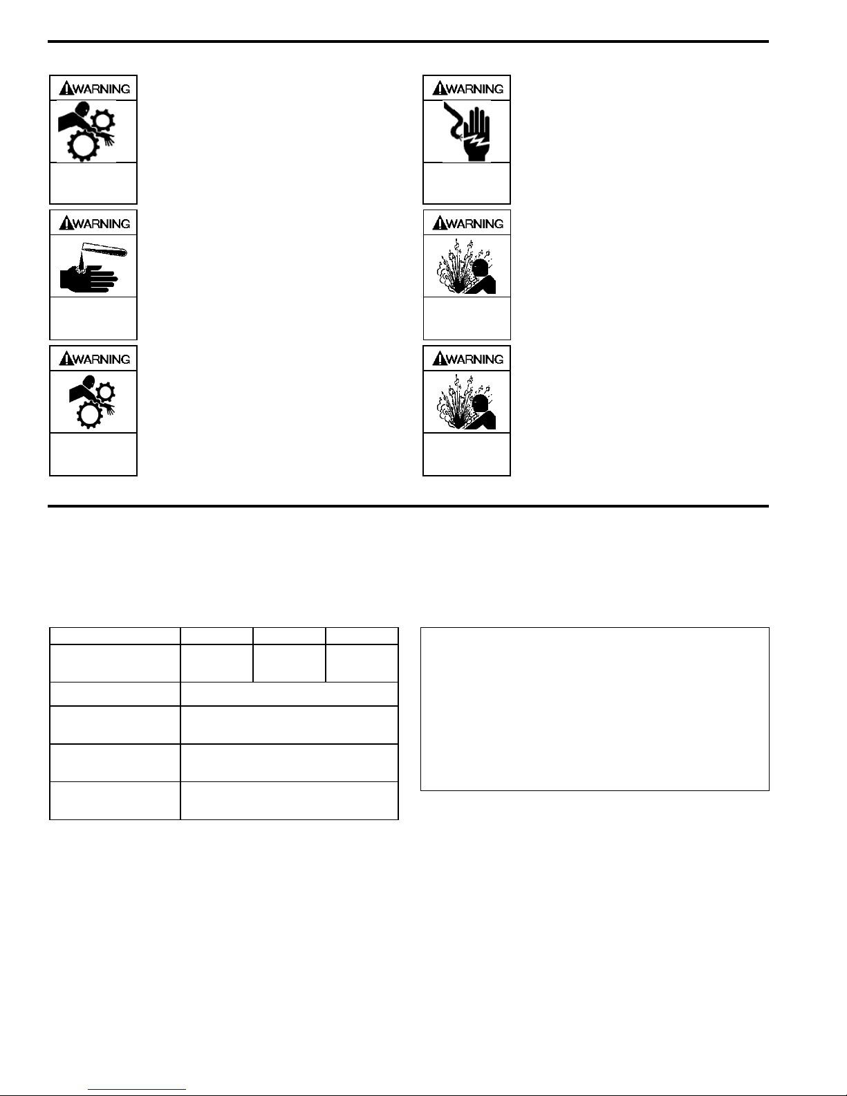
Failure to disconnect and lockout
electrical power or engine drive before
attempting maintenance can cause
Hazardous
machinery can
cause serious
personal injury.
severe personal injury or death
Hazardous voltage.
Can shock, burn or
cause death.
If pumping hazardous or toxic fluids,
system must be flushed and
decontaminated, inside and out, prior to
Hazardous or toxic
fluids can cause
serious injury.
performing service or maintenance
Operation without guards in place can
cause serious personal injury, major
property damage, or death.
Do not operate
without guard
in place
Hazardous pressure
can cause personal
injury or property
damage
Hazardous pressure
can cause personal
injury or property
damage
Failure to disconnect and lockout
electrical power before attempting
maintenance can cause shock, burns or
death
Disconnecting fluid or pressure
containment components during pump
operation can cause serious personal
injury, death or major property damage
Failure to relieve system pressure prior
to performing pump service or
maintenance can cause personal injury
or property damage.
PUMP DATA
PUMP IDENTIFICATION
A pump Identification tag, containing the pump serial number, I.D. number, and model designation, is attached to each pump. It is
recommended that the data from this tag be recorded and filed for future reference. If replacement parts are needed, or if
information pertaining to the pump is required, this data must be furnished to a Blackmer representative.
TECHNICAL DATA
Maximum Pump
Speed
Maximum Viscosity
Maximum Operating
Temperature *
Maximum
Differential Pressure
Maximum Working
Pressure
* Maximum operating limits are dependent on the materials of
construction. See Blackmer Material Specs 101-095.
2”, 2.5” 3” 4”
780 RPM 640 RPM 520 RPM
20,000 SSU (4,250 cP)
240 – 300°F (115 – 149°C)
125 psi (8.6 Bar)
175 psi (12.1 Bar)
INITIAL PUMP START UP INFORMATION
Model No.: ____________________________________
Serial No.: _______________________________ _____
ID No.: _______________________________________
Date of Installation: _____________________________
Inlet Gauge Reading: _________________________ ___
Discharge Gauge Reading: ____________________ ___
Flow Rate: _____________________________________
101-B00 page 2/16
INSTALLATION
NOTICE:
Blackmer pumps must only be installed in systems
designed by qualified engineering personnel. System
design must conform with all applicable regulations and
codes and provide warning of all system hazards.
Install, ground and wire to local and
National Electrical Code requirements.
Install an all-leg disconnect switch near
the unit motor.
Disconnect and lockout electrical power
Hazardous voltage.
Can shock, burn or
cause death.
Motors equipped with thermal protecti on automatically
disconnect motor electrical circuit when overload exists.
Motor can start unexpectedly and without warning.
before installation or service
Electrical supply MUST match motor
PRE-INSTALLATION CLEANING
NOTICE:
New pumps contain residual test fluid and rust inhibitor.
If necessary, flush pump prior to use.
Foreign matter entering the pump WILL cause extensive
damage. The supply tank and intake piping MUST be
cleaned and flushed prior to pump installation and operation.
LOCATION AND PIPING
Pump life and performance can be significantly reduced
when installed in an improperly designed system. Before
starting the layout and installation of the piping system,
review the following:
1. Locate the pump as near as possible to the source of
supply to avoid excessive inlet pipe friction.
2. The inlet line MUST be at least as large as the intake
port on the pump. The inlet piping should slope
downward to the pump without any upward loops.
Eliminate restrictions such as sharp bends; globe valves,
unnecessary elbows, and undersized strainers.
3. It is recommended a strainer be installed in the inlet line
to protect the pump from foreign matter. The strainer
should be located at least 24" (0.6m) from the pump,
and have a net open area of at least four times the area
of the intake piping. For viscosities greater than 1000
SSU, consult the strainer manufacture instructions.
Strainers must be cleaned regularly to avoid pump
starvation.
4. The intake system must be free of air leaks.
5. Expansion joints, placed at least 36" (0.9m) from the
pump, will compensate for expansion and contraction of
the pipes. Contact the flexible connector/hose
manufacturer for required maintenance/care and design
assistance in their use.
6.
Install pressure gauges in the NPT ports provided in the
pump casing to check pump at start up.
7. ALL piping and fittings MUST be properly supported to
prevent any piping loads from being placed on the pump.
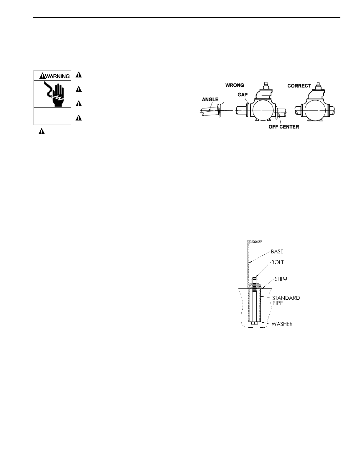
8. Check alignment of pipes to pump to avoid strains which
might later cause misalignment. See Figure 1. Unbolt
flanges or break union joints. Pipes should not spring
away or drop down. After pump has been in operation
for a week or two, completely recheck alignment.
Figure 1
9. When pumping liquids at elevated temperature,
provisions should be made to compensate for expansion
and contraction of the pipes, especially when long pipe
lines are necessary. Steel pipe expands approximately
3/4” (1.9 cm) per 100 feet (30.49 m) per 100°F (37.8°C)
rise in temperature.
PUMP MOUNTING
A solid foundation reduces noise and vibration, and will
improve pump performance. On permanent installations it is
recommended the pumping unit be secured by anchor bolts
as shown in Figure 2. This arrangement allows for slight
shifting of position to accommodate alignment with the
mounting holes in the base plate.
Figure 2 - Pipe Type Anchor Bolt Box
For new foundations, it is suggested that the anchor bolts be
set in concrete. When pumps are to be located on existing
concrete floors, holes should be drilled into the concrete to
hold the anchor bolts.
When installing units built on channel or structural steel type
bases, use care to avoid twisting the base out of shape when
anchor bolts are tightened. Shims should be used under the
edges of the base prior to tightening of the anchor bolts to
prevent distortion.
101-B00 page 3/16
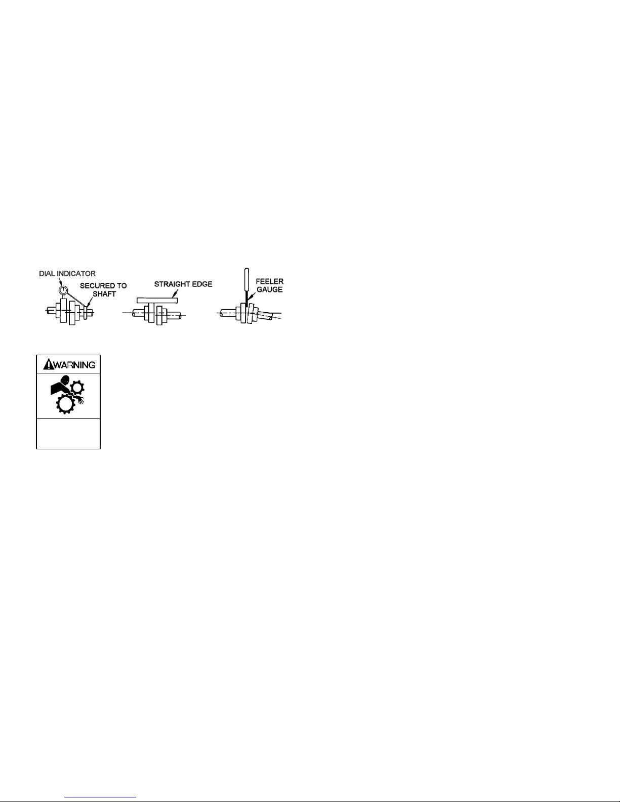
COUPLING ALIGNMENT
The pump must be directly coupled to a gear and/or driver
with a flexible coupling. Verify coupling alignment after
installation of new or rebuilt pumps. Both angular and
parallel coupling alignment MUST be maintained between
the pump, gear, motor, etc. in accordance with
manufacturer’s instructions. See Figure 3.
1. Parallel alignment: The use of a laser alignment tool or
dial indicator is preferred. If a laser alignment tool or dial
indicator is not available, use a straightedge. Turn both
shafts by hand, checking the reading through one
complete revolution. Maximum offset should be less
than .005" (.127 mm).
2. Angular alignment: Insert a feeler gauge between the
coupling halves. Check the spacing at 90° increments
around the coupling (four checkpoints). Maximum
variation should not exceed .005" (.127 mm). Some
laser alignment tools will check angular alignment as
well.
3. Replace the coupling guards after setting alignment.
Figure 3 – Alignment Check
Operation without guards in place can
cause serious personal injury, major
property damage, or death.
Do not operate
without guard
in place
PUMP ROTATION
A right-hand pump rotates clockwise with the intake and relief
valve on the right side, when viewed from the driven end.
A left-hand pump rotates counterclockwise with the intake
and relief valve on the left side, when viewed from the driven
end.
NOTICE:
On GX models, the gear reducer input shaft will rotate in
the opposite direction of the pump shaft. For example,
on a right-hand GX pump, the gear reducer shaft will
rotate counterclockwise.
NOTICE:
Confirm correct pump rotation by checking the pump
rotation arrows respective to pump driver rotation.
TO CHANGE PUMP ROTATION
To reverse rotation, the pump must be disassembled then
reassembled with the shaft on the opposite side of the pump.
See the ‘Maintenance’ section for instructions.
CHECK VALVES
The use of check valves or foot valves in the supply tank is
not recommended with self-priming, positive displacement
pumps.
If the possibility of liquid backflow exists when the pump is
off, a check valve in the pump discharge piping is
recommended because the pump can motor in the reverse
rotation and create undue stress on all attached components.
Never start a pump when it is rotating in the reverse rotation
as the added starting torque can damage the pump and
related equipment.
GEAR REDUCER ALIGNMENT – GX MODELS
The reducer can be rotated on its mounting to raise or lower
the input shaft to facilitate alignment to the motor shaft. To do
so, first loosen the four clamp capscrews (20C) and the two
setscrews (33) in the gear reducer spool flange. The reducer
is then free to rotate. If necessary, tap it lightly with a soft
faced mallet. When aligning the reducer, verify the alignment
of the coupling halves as indicated in “Coupling Alignment”
section.
NOTICE:
To determine maximum variation of gear reducer shaft
alignment, refer to Blackmer GX model dimension pages
101-B00 Page 4/16
OPERATION
Operation without guards in place can
cause serious personal injury, major
property damage, or death.
Do not operate
without guard
in place
Disconnecting fluid or pressure
containment components during pump
operation can cause serious personal
Hazardous pressure
can cause personal
injury or property
damage
injury, death or major property damage
PRE-START UP CHECK LIST
1. Check the alignment of the pipes to the pump. Pipes
should be supported so that they do not spring away or
drop down when pump flanges or union joints are
disconnected.
2. Verify proper coupling alignment.
3. On GX models, check the oil l evel in the gear reducer.
Refer to ‘Lubrication’ in the ‘Gear Reducer Maintenance’
section of this manual.
NOTICE:
Blackmer gear reducers are not lubricated at the factory.
Oil MUST be added before initial pump start-up
4. On GX models shipped without the gear reducer
attached, the inboard bearings are NOT greased at
the factory. The inboard bearing MUST be greased
after installation of the gear reducer and prior to
initial pump start up. See “Pump Lubrication” in the
Maintenance section of this manual.
5. Check the entire pumping system to verify that the proper
inlet and discharge valves are fully open, and that the
drain valves and other auxiliary valves are closed.
6. Install vacuum and pressure gauges on the pump in the
1/4” NPT connections provided to check suction and
discharge conditions after pump start-up.
7. Check the wiring of the motor, and briefly turn on the
power to make sure that the pump rotates in the direction
of the rotation arrow.
Failure to relieve system pressure prior
to performing pump service or
maintenance can cause personal injury
Hazardous pressure
can cause personal
injury or property
damage
or property damage.
Pumps operating against a closed valve
can cause system failure, personal
injury and property damage
Hazardous pressure
can cause personal
injury or property
damage
START UP PROCEDURES
NOTICE:
Consult the "General Pump Troubleshooting" section of
this manual if difficulties during start up are
experienced.
1. Start the motor. Priming should occur within one minute.
2. Check the suction and discharge pressure to see if the
pump is operating within the expected conditions.
Record pressures in the ‘Initial Start Up Information’
section.
3. Check for leakage from the p iping and equipment.
4. Check for overheating, e xces sive no ise or vibration of the
pump, reducer, and motor.
5. Check the flow rate to ensure the pump is operating
within the expected parameters. Record flow rate in the
‘Initial Start Up Information’ section.
6. Check the pressure setting of the relief valve by briefly
closing a valve in the discharge line and reading the
pressure gauge. This pressure should be 20 psi (1.4 bar)
higher than the maximum operating pressure.
Do not run the pump for more than 15 seconds with
the discharge valve completely closed.
If adjustments need to be made, refer to "Relief Valve
Setting & Adjustment."
Incorrect settings of the pressure relief
valve can cause pump component
failure, personal injury, and property
Hazardous pressure
can cause personal
injury or property
damage
damage.
101-B00 Page 5/16
 Loading...