

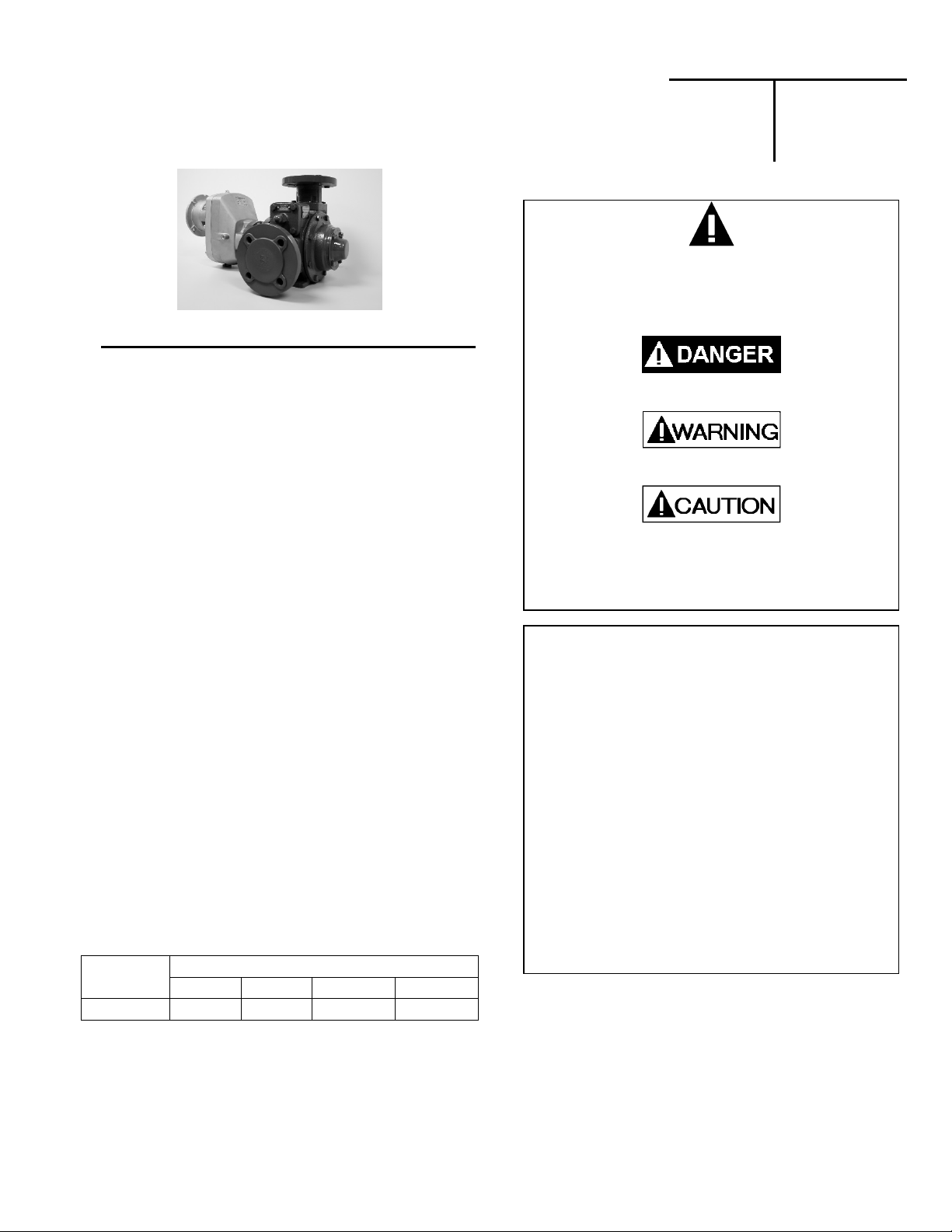
BLACKMER GNXH2A, GNXH2.5A, GNXH3A, GNXH4A, GNX2A Installation, Operation And Maintenance Instructions
...Page 1
BLACKMER POWER PUMPS
A
INSTALLATION OPERATION AND MAINTENANCE INSTRUCTIONS
MODELS: GNX(H)2A, GNX(H)2.5A, GNX(H)3A, GNX(H)4A
This is a SAFETY ALERT SYMBOL.
When you see this symbol on the product, or in the
TABLE OF CONTENTS Page PUMP DAT
Technical Data .................................................... 2
Initial Pump Start Up Information ........................ 2
INSTALLATION
Pre-Installation Cleaning ..................................... 3
Location and Piping ............................................. 3
Mounting ............................................................. 3
Coupling Alignment ............................................. 4
Motor Coupling Installation………………………...4
Gear Reducer Alignment – GNX(H) Models ....... 4
Pump Rotation .................................................... 6
To Change Pump Rotation .................................. 6
Check Valves ...................................................... 6
OPERATION
Pre-Start Up Check List ...................................... 7
Start Up Procedures ............................................ 8
Running the Pump in Reverse Rotation .............. 9
Flushing the Pump .............................................. 9
Pump Relief Valve ............................................... 9
Relief Valve Setting and Adjustment ................... 9
PUMP MAINTENANCE
Pump Lubrication ................................................. 10
Strainers............................................................... 11
Vane Replacement .............................................. 11
Pump Disassembly .............................................. 11
Parts Replacement .............................................. 11
Pump Assembly ................................................... 12
GEAR REDUCER MAINTENANCE ............................ 14
PUMP TROUBLE SHOOTING .................................... 16
GEAR REDUCER TROUBLE SHOOTING ................. 17
NOTE: Numbers in parentheses following individual parts
indicate reference numbers on Blackmer Parts Lists.
Blackmer pump manuals and parts lists may be obtained
from Blackmer's website (www.blackmer.com) or by
contacting Blackmer Customer Service.
PUMP PUMP PARTS LIST
MODEL 2” 2.5” 3” 4”
GNX(H)
101-C01 101-C02 101-C03 101-C04
manual, look for one of the following signal words and be
alert to the potential for personal injury, death or major
Warns of hazards that WILL cause serious personal injury,
death or major property damage.
Warns of hazards that CAN cause serious personal injury,
death or major property damage.
Warns of hazards that CAN cause personal injury
Indicates special instructions which are very
important and must be followed.
Blackmer Pumps MUST only be installed in systems, which
have been designed by qualified engineering personnel.
The system MUST conform to all applicable local and
national regulations and safety standards.
This manual is intended to assist in the installation and
operation of the Blackmer power pumps, and MUST be kept
with the pump.
Pump service shall be performed by qualified technician s
ONLY. Service shall conform to all applicable local and
national regulations and safety standards.
Thoroughly review this manual, all instructions and hazard
warnings, BEFORE performing any work on the pump.
Maintain ALL system and pump operation and hazard
warning decals.
961224
INSTRUCTIONS NO. 101-C00
Section
Effective
Replaces
101
Mar 2019
Oct 2018
SAFETY DATA
property damage
or property damage.
NOTICE:
NOTICE:
Page 2
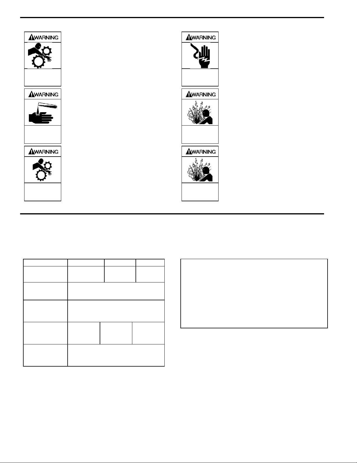
SAFETY DATA
Failure to disconnect and lockout
electrical power or engine drive before
attempting maintenance can cause
Hazardous
machinery can
cause serious
personal injury.
severe personal injury or death
Hazardous voltage.
Can shock, burn or
cause death.
If pumping hazardous or toxic fluids,
system must be flushed and
decontaminated, inside and out, prior to
Hazardous or toxic
fluids can cause
serious injury.
performing service or maintenance
Operation without guards in place can
cause serious personal injury, major
property damage, or death.
Do not operate
without guard
in place
Hazardous pressure
can cause personal
injury or property
Hazardous pressure
can cause personal
injury or property
damage
damage
Failure to disconnect and lockout
electrical power before attempting
maintenance can cause shock, burns or
death
Disconnecting fluid or pressure
containment components during pump
operation can cause serious personal
injury, death or major property damage
Failure to relieve system pressure prior
to performing pump service or
maintenance can cause personal injury
or property damage.
PUMP DATA
PUMP IDENTIFICATION
A pump Identification tag, containing the pump serial number, I.D. number, and model designation, is attached to each p ump. It is
recommended that the data from this tag be recorded and filed for future reference. If replacement parts are needed, or if
information pertaining to the pump is required, this data must be furnished to a Blackmer representative.
TECHNICAL DATA
Maximum Pump
Speed
2”, 2.5”
815 RPM 700 RPM 563 RPM
Maximum
Viscosity
Maximum
Operating
Temperature *
Maximum
Differential
Pressure
125 psi
(8.6 Bar)
(115 – 149°C)
Maximum
Working
Pressure
* Maximum operating limits are dependent on the materials of
construction. See Blackmer Material Specs 101-096.
3” 4”
20,000 SSU
(4,250 cP)
240 – 300°F
100 psi
(6.9 bar)
100 psi
(6.9 bar)
175 psi
(12.1 Bar)
INITIAL PUMP START UP INFORMATION
Model No.: __________________________ __________
Serial No.: _______________________________ _____
ID No.: _______________________________________
Date of Installation: _____________________________
Inlet Gauge Reading: ____________________________
Discharge Gauge Reading: _______________________
Flow Rate: ________________________ _____________
101-C00 page 2/20
Page 3
INSTALLATION
NOTICE:
Blackmer pumps must only be installed in systems
designed by qualified engineering personnel. System
design must conform with all applicable regulations and
codes and provide warning of all system hazards.
Install, ground and wire to local and
National Electrical Code requirements.
Install an all-leg disconnect switch near
the unit motor.
Disconnect and lockout electrical power
Hazardous voltage.
Can shock, burn or
cause death.
Motors equipped with thermal protection automatically
disconnect motor electrical circuit when overload exists.
Motor can start unexpectedly and without warning.
before installation or service
Electrical supply MUST match motor
nameplate specifications.
PRE-INSTALLATION CLEANING
NOTICE:
New pumps contain residual test fluid and rust inhibitor.
If necessary, flush pump prior to use.
Foreign matter entering the pump WILL cause extensive
damage. The supply tank and intake piping MUST be
cleaned and flushed prior to pump installation and operation.
LOCATION AND PIPING
Pump life and performance can be significantly reduced
when installed in an improperly designed system. Before
starting the layout and installation of the piping system,
review the following:
1. Locate the pump as near as possible to the source of
supply to avoid excessive inlet pipe friction.
2. The inlet line MUST be at least as large as the intake
port on the pump. The inlet piping should slope
downward to the pump without any upward loops.
Eliminate restrictions such as sharp bends; globe valves,
unnecessary elbows, and undersized strainers.
3. It is recommended a strainer be installed in the inlet line
to protect the pump from foreign matter. The strainer
should be located at least 24" (0.6m) from the pump,
and have a net open area of at least four times the area
of the intake piping. For viscosities greater than 1000
SSU, consult the strainer manufacture instructions.
Strainers must be cleaned regularly to avoid pump
starvation.
4. The intake system must be free of air leaks.
5. Expansion joints, placed at least 36" (0.9m) from the
pump, will compensate for expansion and contraction of
the pipes. Contact the flexible connector/hose
manufacturer for required maintenance/care and design
assistance in their use.
6. Install pressure gauges in the NPT ports provided in the
pump casing to check pump at start up.
7. ALL piping and fittings MUST be properly supported to
prevent any piping loads from being placed on the pump.
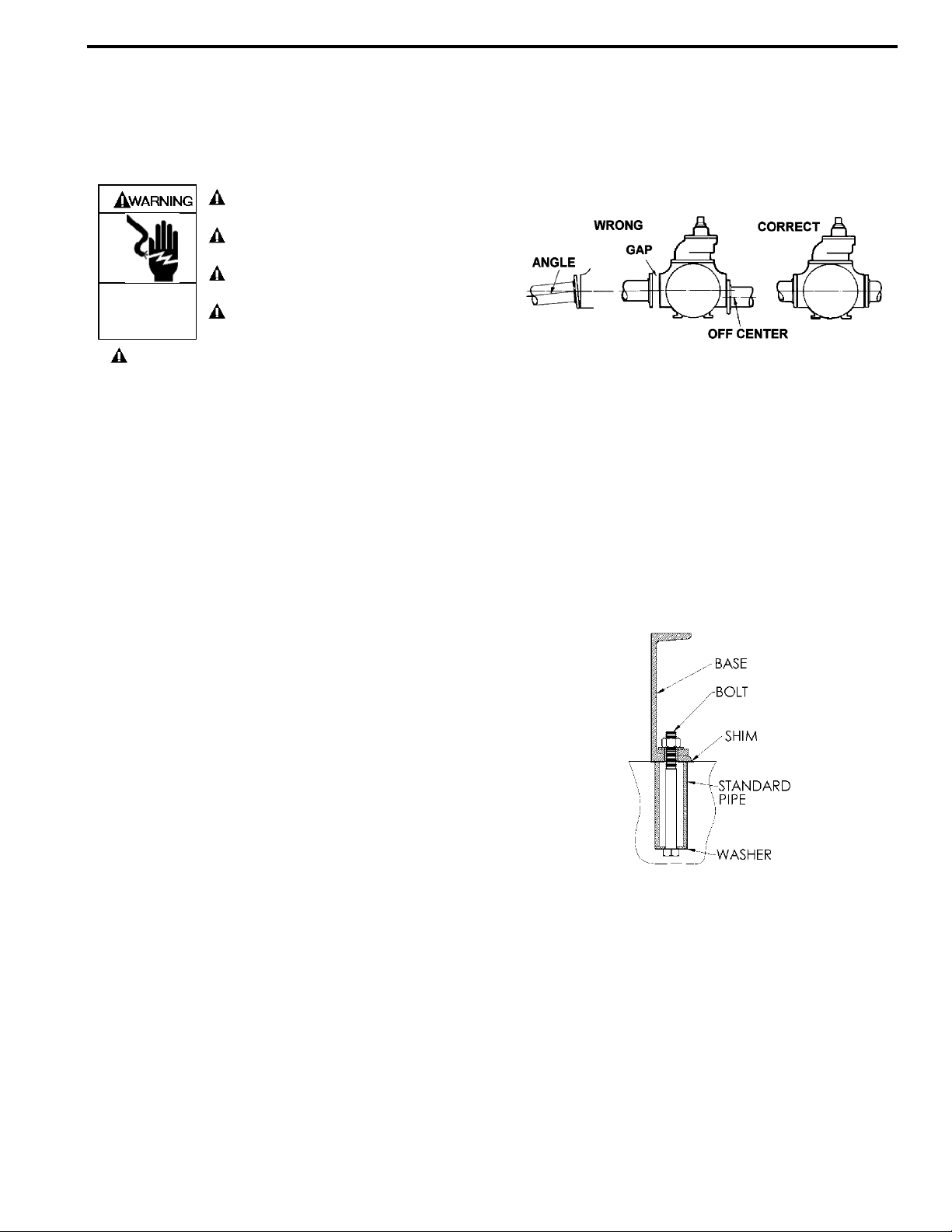
8. Check alignment of pipes to pump to avoid strains which
might later cause misalignment. See Figure 1. Unbolt
flanges or break union joints. Pipes should not spring
away or drop down. After pump has been in operation
for a week or two, completely recheck alignment.
Figure 1
9. When pumping liquids at elevated temperatur e,
provisions should be made to compensate for expansion
and contraction of the pipes, especially when long pipe
lines are necessary. Steel pipe expands approximately
3/4” (1.9 cm) per 100 feet (30.49 m) per 100°F (37.8°C)
rise in temperature.
PUMP MOUNTING
A solid foundation reduces noise and vibration, and will
improve pump performance. On permanent installations it is
recommended the pumping unit be secured by anchor bolts
as shown in Figure 2. This arrangement allows for slight
shifting of position to accommodate alignment with the
mounting holes in the base plate.
Figure 2 - Pipe Type Anchor Bolt Box
For new foundations, it is suggested that the anchor bolts be
set in concrete. When pumps are to be located on existing
concrete floors, holes should be drilled into the concrete to
hold the anchor bolts.
When installing units built on channel or structural steel type
bases, use care to avoid twisting the base out of shape when
anchor bolts are tightened. Shims should be used under the
edges of the base prior to tightening of the anchor bolts to
prevent distortion.
101-C00 page 3/20
Page 4
COUPLING ALIGNMENT – FOOTED
GEARBOX
The following pertains to units with non-standard, footed
gearboxes only. Standard GNX(H) units will not require
manual alignment.
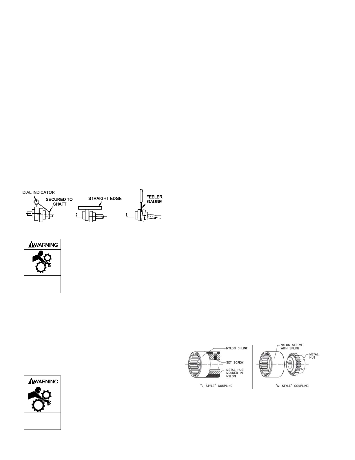
The pump must be directly coupled to a gear and/or driver
with a flexible coupling. Verify coupling alignment after
installation of new or rebuilt pumps. Both angular and
parallel coupling alignment MUST be maintained between
the pump, gear, motor, etc. in accordance with
manufacturer’s instructions. See Figure 3.
1. Parallel alignment: The use of a laser alignment tool or
dial indicator is preferred. If a laser alignment tool or dial
indicator is not available, use a straightedge. Turn both
shafts by hand, checking the reading through one
complete revolution. Maximum offset should be less
than .005" (.127 mm).
2. Angular alignment: Insert a feeler gauge between the
coupling halves. Check the spacing at 90° increments
around the coupling (four checkpoints). Maximum
variation should not exceed .005" (.127 mm). Some
laser alignment tools will check angular alignment as
well.
3. Replace the coupling guards after setting alignment.
Figure 3 – Alignment Check
Operation without guards in place can
cause serious personal injury, major
property damage, or death.
Do not operate
without guard
in place
ALIGNMENT – GNX(H) MODELS
The motor, gearbox, and pump are rigidly connected with
bolted, flange connections. These flanges ensure the motor
shaft, gearbox shafts, and pump shaft are aligned correctly,
without the need for manual alignment. However, due to
variations in base and foundation geometry the unit will
require shimming to reduce stress on the gearbox and pump
adapter. See PRESTART CHECKLIST section for details.
NEMA MOTOR COUPLING ADAPTER
Motor adapters allow for easy installation and removal of
industry standard motors. Motor adapters consist of a
coupling and an adapter housing that connects the motor to
the gear reducer.
NORD Gear supplies a coupling that is to be mounted on the
motor shaft. It is important that the coupling is properly
positioned.
• For NEMA Input Adapters, follow the Motor Installation
Instructions on page 5.
• For IEC Input Adapters, the supplied coupling will mount
directly against the motor shaft shoulder. No locating
measurements need to be taken.
Couplings
Couplings are made with tough abrasion resistant materials,
which resist most chemicals and petroleum products. They
are electrically isolated (prevent metal to metal contact) and
require no lubrication or maintenance. Depending upon the
size of the C-face input, NORD provides either a gear or a
jaw type coupling.
NORD supplies three different types of couplings depending
on the size of input: “J” style, “M” style and “Jaw” style
coupling.
Following are instructions on how to properly mount each
type of coupling onto the motor.
BoWex® Couplings
NORD C-face adapter input shafts have a machined spline
on the end. NORD incorporates two styles of BoWex®
couplings, the “J” and “M” styles. The “J” style is a one-piece
coupling with a metal hub and nylon spline. The “M” style is a
two-piece coupling – the metal hub and a nylon sleeve. Nylon
and steel components allow them to operate in high ambient
temperatures without lubrication or maintenance.
• Nylon sleeves resist dirt, moisture, most chemicals and
petroleum products
• No lubrication required
• Operating Conditions: -22ºF - 212ºF (-30ºC - 100ºC)
• Higher temperature coupling sleeve available up to 250ºF
(120ºC)
• Special bore available
Hazardous
machinery can
cause serious
personal injury.
Failure to disconnect and lockout
electrical power or engine drive before
attempting maintenance can cause
severe personal injury or death
NEMA Motor Coupling Styles
101-C00 Page 4/20
Page 5
BoWex® Couplings Mechanical Ratings “J” Style (NEMA & IEC)
Coupling
Type
BoWex®
J14
BoWex®
J24
BoWex®
J28
Rated Torque
Cont. Peak
(Lb-in)
(N-m)
44.3
5
106
12
398
45
88.5
10
212
24
1,195
135
Input
Adapter
Sizes
N56C 5/8”
N140TC 7/8”
N180TC
N180TC1
Bore
Size
1-1/8”
BoWex® Couplings Mechanical Ratings “M” Style (NEMA & IEC)
Coupling
Type
BoWex®
M38
BoWex®
M42
BoWex®
M48
*GNX(H)2/2.5 N250TC Frame size uses BoWex® M38
*GNX(H)3/4 N250TC Frame size uses BoWex
Rotex® Couplings
The cast iron jaw type couplings have an integral urethane
“spider” that provides smooth transmission of the motor
torque. A set screw on the coupling prohibits axial movement
along the motor shaft.
• Excellent shock and vibration dampening
• Excellent resistance to oils and most chemicals
• No metal-to-metal contact
• Operating Conditions: -22ºF - 195ºF (-30ºC - 90ºC)
• Higher temperature material (Hytrel) spider available up to
230ºF (110ºC)
• Low temperature materials available upon request
• Special bores available
Rated Torque
Cont. Peak
(Lb-in)
(N-m)
708
80
885
100
1,239
140
2,124
240
2,655
300
3,717
420
Input
Adapter
Sizes
N180TC,
N210TC,
N250TC*
N250TC* 1-5/8”
N280TC 1-7/8”
®
M42
Bore
Size
1-1/8”,
1-3/8”
Rotex® Couplings Mechanical Ratings “R” Style (NEMA & IEC)
Coupling
Type
Rotex®
R65
Rotex®
R90
Rated Torque
Cont. Peak
(Lb-in)
(N-m)
5,532
625
21,242
2400
11,063
1,250
42,484
4800
Input
Adapter
Sizes
N320TC 2-3/8”
N360TC 1-5/8”
Bore
Size
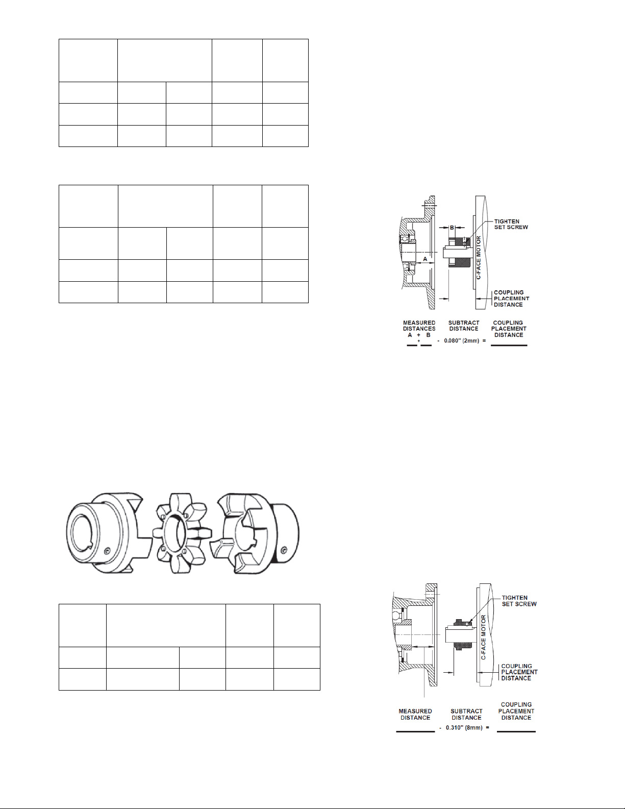
“J” Style Coupling NEMA C-face Motor Installation
1. Measure the distance from the face of the input adapter
to the face of the splined shaft and record that
measurement as A in the equation below.
2. Measure depth of coupling engagement zone and record
the measurement as “B” in the equation below.
101-C00 Page 5/20
3. Add “A” + “B” and subtract 0.08” (~2mm) from the
distance. This needs to be done so that the coupling will
not be preloaded after installation!
4. Use that measurement to locate the coupling from the
face of the motor onto the shaft.
5. Once in place, tighten the set screw to lock the coupling
in place. It is recommended that the key is staked or
bonded (Loctite) in place to prohibit the key from
vibrating out.
6. Mount the motor onto the input adapter with customer
supplied bolts. Make sure that the coupling from the
adapter and the motor engage securely. Use lock
washers or Loctite to prohibit bolts from becoming loose
from vibration.
“J” Style NEMA Motor Coupling Installation
“M” Style Coupling NEMA C-face Motor Installation
1. Measure the distance from the face of the input adapter
to the face of the splined shaft & record that
measurement.
2. Subtract 0.31” (~8mm) from the distance. This needs to
be done so that the coupling will not be preloaded after
installation!
3. Use that measurement to locate the coupling from the
face of the motor onto the shaft.
4. Once in place, tighten the set screw to lock the coupling
in place. It is recommended that the key is staked or
bonded (Loctite) in place to prohibit the key from
vibrating out.
5. Mount the motor onto the input adapter with customer
supplied bolts. Make sure that the coupling from the
adapter and the motor engage securely. Use lock
washers or Loctite to prohibit bolts from becoming loose
from vibration.
“M” Style NEMA Motor Coupling Installation
Page 6
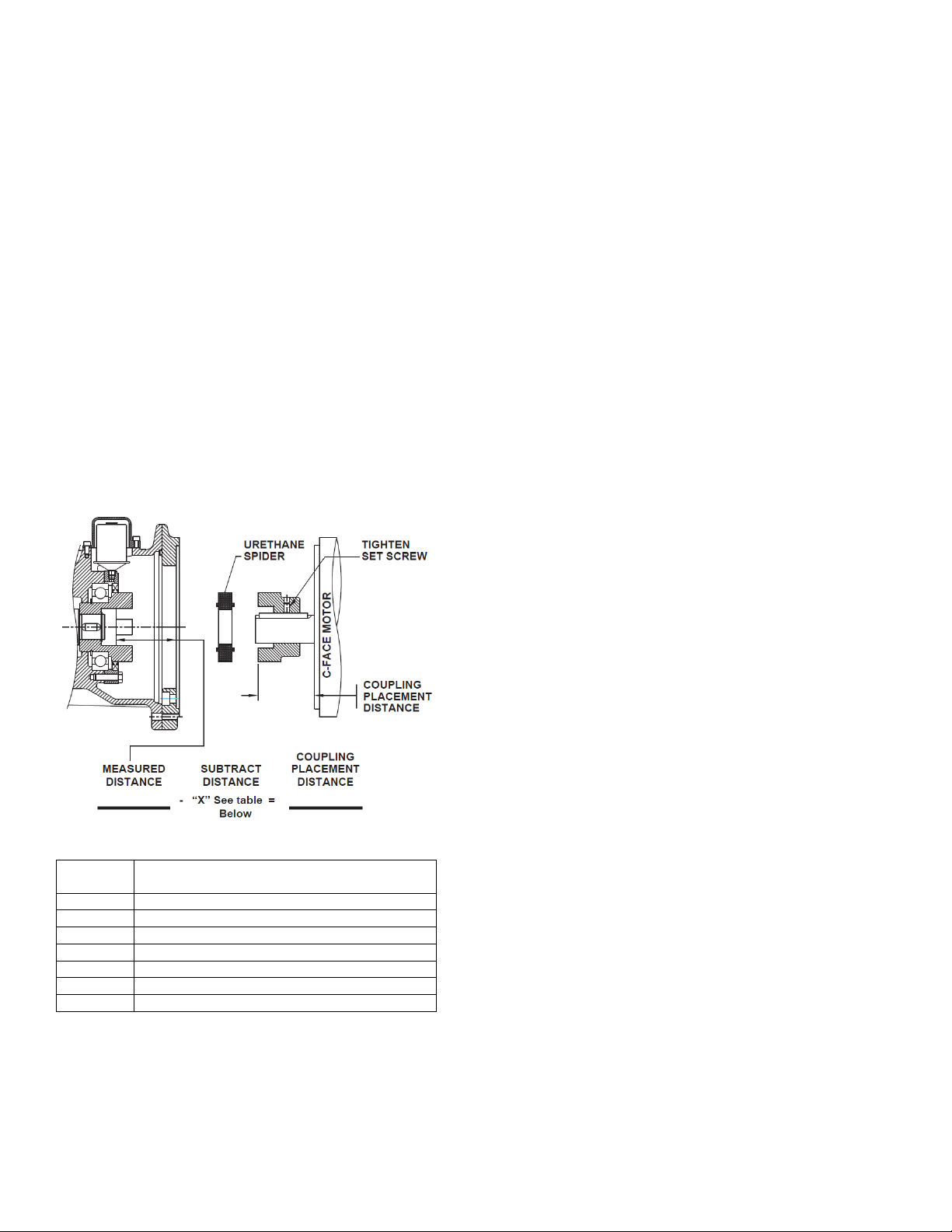
“Jaw” Style Coupling NEMA C-face Installation
1. Measure the distance from the face of the input adapter
to the face of the coupling as shown and record that
measurement.
2. Subtract the “X” dimension from the measured distance.
This needs to be done so that the coupling will not be
preloaded after installation!
3. Use that measurement to locate the coupling from the
face of the motor onto the shaft.
4. The metal portion of the coupling should be heated up
prior to assembly, generally 250ºF to 300ºF (120ºC to
150ºC).
Notice: DO NOT HEAT URETHANE SPIDER
5. Once in place, tighten the setscrew to lock coupling in
place. Let the coupling cool down before placing the
spider into the jaws. It is recommended that the key is
staked or bonded (Loctite) in place to prohibit the key
from vibrating out.
6. Mount the motor onto the input adapter with customer
supplied bolts. Make sure that the coupling from the
adapter and the motor engage securely. Use lock
washers or Loctite to prohibit bolts from becoming loose
from vibration.
PUMP ROTATION
A right-hand pump rotates clockwise with the intake and relief
valve on the right side, when viewed from the driven end.
A left-hand pump rotates counterclockwise with the intake
and relief valve on the left side, when viewed from the driven
end.
NOTICE:
On GNX(H) models, the gear reducer input shaft will
rotate in the opposite direction of the pump shaft. For
example, on a right-hand GNX(H) pump, the gear reducer
shaft will rotate counterclockwise. The motor fan can be
used to ensure proper rotation.
NOTICE:
Confirm correct pump rotation by checking the pump
rotation arrows respective to pump driver rotation.
TO CHANGE PUMP ROTATION
To reverse rotation, the pump must be disassembled then
reassembled with the shaft on the opposite side of the pump.
See the ‘Maintenance’ section for instructions.
CHECK VALVES
The use of check valves or foot valves in the supply tank is
not recommended with self-priming, positive displacement
pumps.
If the possibility of liquid backflow exists when the pump is
off, a check valve in the pump discharge piping is
recommended because the pump can motor in the reverse
rotation and create undue stress on all attached components.
Never start a pump when it is rotating in the reverse rotation
as the added starting torque can damage the pump and
related equipment.
Jaw Style NEMA Motor Coupling Installation
Coupling
Size
R14 0.06” (1.5 mm)
R19 & 24 0.08” (2.0 mm)
R28 0.10” (2.5 mm)
R38 & 42 0.12” (3.0 mm)
R48 0.14” (3.5 mm)
R65 0.18” (4.5 mm)
R90 0.22” (5.5 mm)
(Subtract this value from measured distance)
“X”
101-C00 Page 6/20
Page 7
OPERATION
Operation without guards in place can
cause serious personal injury, major
property damage, or death.
Do not operate
without guard
in place
Disconnecting fluid or pressure
containment components during pump
operation can cause serious personal
Hazardous pressure
can cause personal
injury or property
damage
injury, death or major property damage
PRE-START UP CHECK LIST
1. Check the alignment of the pipes to the pump. Pipes
should be supported so that they do not spring away or
drop down when pump flanges or union joints are
disconnected.
2. Verify proper coupling alignment on long coupled units.
3. For GNX(H) models:
3a. Bolt down the pump foot, while supporting the motor
with an appropriate lifting device (e.g. crane)
3b. Place a .125” thick shim under each of the motor
mounting holes
3c. Slowly lower the motor until it is unsupported
3d. Try pulling out each of the shims, while noticing the
the pull tension
3e. If the shims closest to the motor shaft easily pull out,
increase the shim thickness the same at all
locations and recheck
3f. If the shims furthest from the motor shaft easily pull
out, decreas e the shim thickness the same at all
locations and recheck
3g. The unit is properly shimmed when all 4 motor
shims have the same amount of tension when
pulled
3h. Bolt down the motor with the appropriate fastener.
4. The GNX(H)2 and GNX(H)2.5 gearbox will be shipped
with Mobil SHC630 synthetic oil. The GNX(H)3 and
GNX(H)4 will be shipped with Mobil SHC Gear 220
synthetic oil. If replacing the oil, refer to the GEAR
REDUCER MAINTENANCE section.
Failure to relieve system pressure prior
to performing pump service or
maintenance can cause personal injury
Hazardous pressure
can cause personal
injury or property
damage
or property damage.
Pumps operating against a closed valve
can cause system failure, personal
injury and property damage
Hazardous pressure
can cause personal
injury or property
damage
after installation of the gear reducer and prior to
initial pump start up. See “Pump Lubrication” in the
Maintenance section of this manual.
6. Check the entire pumping system to verify that the proper
inlet and discharge valves are fully open, and that the
drain valves and other auxiliary valves are closed.
7. Install vacuum and pressure gauges on the pump in the
1/4” NPT connections provided to check suction and
discharge conditions after pump start-up.
8. Check the wiring of the motor, and briefly turn on the
power to make sure that the pump rotates in the direction
of the rotation arrow.
NOTICE:
The GNX(H) Gear Reducer is shipped with the correct
amount of synthetic oil. If the unit will be orientated in a
non-standard way, please consult the factory for
lubrication information
5. On GNX(H) models shipped without the gear reducer
attached, the inboard bearings are NOT greased at
the factory. The inboard bearing MUST be greased
101-C00 Page 7/20
Page 8
START UP PROCEDURES
NOTICE:
Consult the "General Pump Troubleshooting" section of
this manual if difficulties during start up are
experienced.
1. Start the motor. Priming should occur within one minute.
2. Check the suction and discharge pressure to see if the
pump is operating within the expected conditions.
Record pressures in the ‘Initial Start Up Information’
section.
3. Check for leakage from the piping and equipment.
4. Check for overheating, excessive noise or vibration of the
pump, reducer, and motor.
5. Check the flow rate to ensure the pump is operating
within the expected parameters. Record flow rate in the
‘Initial Start Up Information’ section.
6. Check the pressure setting of the relief valve by briefly
closing a valve in the discharge line and reading the
pressure gauge. This pressure should be 20 psi (1.4 bar)
higher than the maximum operating pressure.
Do not run the pump for more than 15 seconds with
the discharge valve completely closed.
If adjustments need to be made, refer to "Relief Valve
Setting & Adjustment."
Hazardous pressure
can cause personal
injury or property
damage
Incorrect settings of the pressure relief
valve can cause pump component
failure, personal injury, and property
damage.
101-C00 Page 8/20
Page 9
RUNNING THE PUMP IN REVERSE ROTATION
NOTICE:
Pump should be operated in reverse rotation for no more
than 10 minutes and only when a separate pressure relief
valve is installed to protect the pump from excessive
pressure.
It may be desirable to run the pump in reverse rotation for
system maintenance. The pump will operate satisfactorily in
reverse rotation for a LIMITED time, at a reduced
performance level.
FLUSHING THE PUMP
NOTICE:
If flushing fluid is to be left in the pump for an extended
time, it must be a lubricating, non-corrosive fluid. If a
corrosive or non-lubricating fluid is used, it must be
flushed from the pump immediately.
1. To flush the pump, run the pump with the discharge
valve open and the intake valve closed. Bleed air into
the pump through the intake gauge plug hole or through
a larger auxiliary fitting in the intake piping. Pump air for
30 second intervals to clean out most of the pumpage.
2. Run a system compatible flushing fluid through the pump
for one minute to clear out the remainder of the original
pumpage.
3. To remove the flushing fluid, follow step 1 above.
NOTICE:
After flushing the pump some res idual fluid will remain in
the pump and piping.
NOTICE:
Properly dispose of all waste fluids in accordance with
the appropriate codes and regulations.
PUMP RELIEF VALVE
NOTICE:
The pump internal relief valve is designed to protect the
pump from excessive pressure and must not be used as
a system pressure control valve.
GNX(H) series pumps are fitted with an internal pressure
relief valve that bypasses back to the suction side of the
pump.
Pumping volatile liquids under suction lift may cause
cavitation. Partial closing of the discharge valve WILL result
in internal relief valve chatter and is NOT recommended. For
these applications, install an external system pressure
control valve, and any necessary bypass piping, back to the
storage tank.
A system pressure control valve is also recommended when
operating for extended periods (more than 1 minute) against
a closed discharge valve.
RELIEF VALVE SETTING AND ADJUSTMENT
The relief valve pressure setting is marked on a metal tag
attached to the valve cover. Generally, the relief valve should
be set at least 15 - 20 psi (1.0 - 1.4 Bar) higher than the
operating pressure, or the external bypass valve setting (if
equipped).
Incorrect settings of the pressure relief
valve can cause pump component
failure, personal injury, and property
Hazardous pressure
can cause personal
injury or property
damage
Hazardous or toxic
fluids can cause
serious injury.
DO NOT remove the R /V Cap OR adjust the relief valve
pressure setting while the pump is in operation.
1. To INCREASE the pressure setting, remove the relief
valve cap (1) and gasket (88). Loosen the locknut(3), if
equipped. Turn the adjusting screw (2) inward, or
clockwise. Inspect the R/V cap gasket (88) and replace
as required. Reattach the R/V cap gasket and cap.
2. To DECREASE the pressure setting, remove the relief
valve cap (1) and gasket (88). Loosen the locknut(3), if
equipped. Turn the adjusting screw (2) outward, or
counterclockwise. Inspect the R/V cap gasket (88) and
replace as required. Reattach the R/V cap gasket and
cap.
Refer to the individual Blackmer pump parts lists for various
spring pressure ranges. Unless specified otherwise, pumps
are supplied from the factory with the relief valve adjusted to
the mid-point of the spring range.
damage.
Relief valve cap is exposed to pumpage
and will contain some fluid
101-C00 Page 9/20
Page 10
Hazardous
machinery can
cause serious
personal injury.
Hazardous voltage.
Can shock, burn or
cause death.
Hazardous pressure
can cause personal
injury or property
damage
Hazardous pressure
can cause personal
injury or property
damage
Hazardous or toxic
fluids can cause
serious injury.
Do not operate
without guard
in place
Failure to disconnect and lockout
electrical power or engine drive
before attempting maintenance can
cause severe personal injury or death
Failure to disconnect and lockout
electrical power before attempting
maintenance can cause shock, burns
or death
Failure to relieve system pressure
prior to performing pump service or
maintenance can cause personal
injury or property damage.
Disconnecting fluid or pressure
containment components during pump
operation can cause serious personal
injury, death or major property damage
If pumping hazardous or toxic fluids,
system must be flushed and
decontaminated, inside and out, prior
to performing service or maintenance
Operation without guards in place can
cause serious personal injury, major
property damage, or death.
MAINTENANCE
NOTICE:
Maintenance shall be performed by qualified technicians
only. Follow the appropriate procedures and warnings
as presented in this manual.
SCHEDULED MAINTENANCE
PUMP LUBRICATION
NOTICE:
To avoid possible entanglement in moving parts do not
lubricate pump bearings, gear reducer or any other parts
while the pump is running.
NOTICE:
The inboard bearings of GNX(H) models shipped without
the gear reducer attached are NOT greased at the
factory. The inboard bearing MUST be greased after
installation of the gear reducer and prior to initial pump
start up.
NOTICE:
If pumps are repainted in the field, ensure that the grease
relief fittings (76A) are functioning properly after painting.
Do NOT paint them closed. Remove any excess paint
from the fittings.
Pump bearings should be lubricated every three months at
minimum. More frequent lubrication may be required,
depending on the application and operating conditions.
Recommended Grease:
Mobil® - Mobilgrease XHP222,
Exxon® - RONNEX MP Grease,
or equivalent Lithium grease..
Greasing Procedure:
1. Remove the grease relief fittings (76A) from the bearing
covers (27, 27A).
2. SLOWLY apply grease with a hand gun until grease
begins to escape from the grease relief fitting port. (76)
3. Replace the grease relief fittings (76A).
DO NOT overgrease pump bearings. While it is normal for
some grease to escape from the grease tell-tale hole after
lubrication, excessive grease on pumps equipped with
mechanical seals can cause seal failure.
If equipped with a Blackmer gear reducer, refer to the ‘Gear
Reducer Lubrication’ section of this manual.
PUMP SHAFT/GEARBOX COUPLING
An Anti-Seize compound should be applied to the end of the
pump shaft to help minimize fretting wear between the
gearbox coupling and pump shaft.
Recommended Anti-Seize Compound:
Loctite ® 39901 or equivalent
STRAINERS
Strainers must be cleaned regularly to avoid pump starvation.
Schedule will depend upon the application and conditions.
101-C00 Page 10/20
Page 11
VANE REPLACEMENT
NOTICE:
Maintenance shall be performed by qualified technicians
only. Follow the appropriate procedures and warnings as
presented in manual.
1. Flush the pump per instructions in this manual. Drain and
relieve pressure from the pump and system as required.
2. Remove the head assembly from the outboard
(nondriven) side of the pump according to steps 5 - 8 in
the "Pump Disassembly" section of this manual.
3. Turn the shaft by hand until a vane comes to the top (12
o'clock) position of the rotor. Remove the vane.
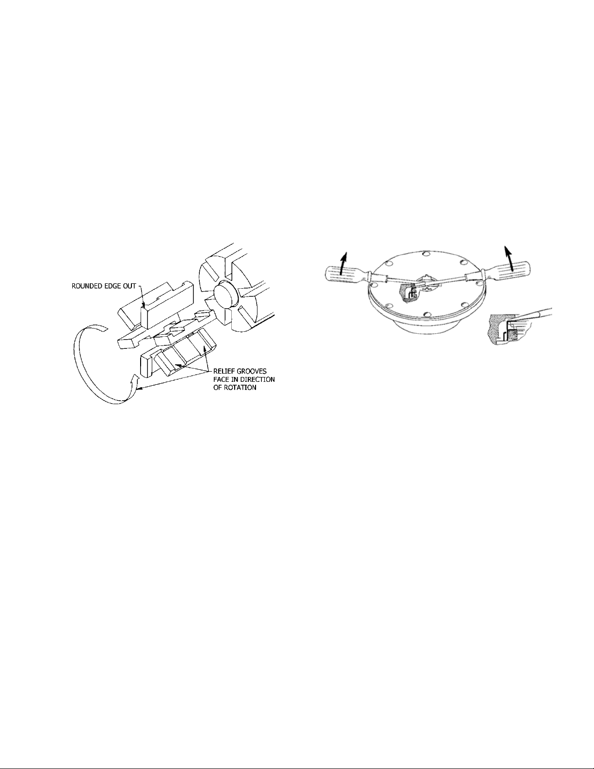
4. Install a new vane, ensuring that the rounded edge is UP,
and the relief grooves are facing towards the direction of
rotation. See Figure 4.
5. Repeat steps 3 and 4 until all vanes have been replaced.
6. Reassemble the pump according to the "Pump
Assembly." section of this manual.
6. GNX(H)4 pump models are equipped with bearing lock
collars (24A). To remove:
a. Remove the jam nuts (24C) and loosen the two set
screws (24B).
b. Slide the lock collar off the shaft.
c. Repeat steps a and b on the opposite shaft end.
7. Remove the head capscrews (21). Gently pry the head
away from the cylinder.
8. Slide the head off the shaft. The head O-ring (72),
bearing (24), and mechanical seal (153) will come off with
the head assembly. Remove and discard the head Oring.
a. Pull the bearing (24) from the housing in the head.
b. To remove the mechanical seal, use two screw
drivers against the backside of the seal jacket to
gently push the seal from the head (see Figure 5.
Use care when placing the screw drivers to prevent
damage to the seal faces. Remove and discard the
seal O-rings.
Figure 4 – Vane Replacement
PUMP DISASSEMBLY
NOTICE:
Follow all hazard warnings and instructions provided in
the “Pump Maintenance” section of this manual.
1. Flush the pump per instructions in this manual. Drain and
relieve pressure from the pump and system as required.
2. Remove the four adapter capscrews (20C) to release the
adapter (135). Remove the motor mounting bolts. With
the aid of a lifting device, slide the motor and gearbox
away from the pump. Refer to “Gear Reducer
Maintenance” for reducer disassembly instructions.
3. Starting on the inboard (driven) end of the pump, clean
the pump shaft thoroughly, making sure the shaft is free
of nicks and burrs. This will prevent damage to the
mechanical seal when the inboard head assembly is
removed.
4. Remove the outboard bearing cover capscrews (28) and
the outboard bearing cover (27) and bearing cover gasket
(26). Discard the bearing cover gasket.
5. The GNX(H)2, 2.5, and 3 are equipped with locknuts
(24A) and lockwashers (24B). To remove:
a. Bend up the engaged lockwasher tang and rotate the
locknut counterclockwise to remove it from the shaft.
b. Slide the lockwasher off the shaft. Inspect the
lockwasher for damage and replace as required.
c. Repeat steps a and b on the opposite shaft end.
101-C00 Page 11/20
Figure 5 – Mechanical Seal Removal
9. Pull the rotor and shaft (13) from the cylinder. While one
hand is pulling the shaft, the other hand should be
cupped underneath the rotor to prevent the vanes (14)
and push rods (77) from falling out. Carefully set the rotor
and shaft aside for future vane replacement and
reassembly.
10. Remove the remaining components from the outboard
side of the pump, as instructed in steps 7 and 8 above.
PARTS REPLACEMENT
1. If any of the O-rings have been removed or disturbed
during disassembly, they should be replaced with new Orings.
NOTE: PTFE O-rings should be heated in hot water to
aid installation.
2. Excessive or continuous leakage from the tell-tale hole in
the bearing cover may be an indication of a damaged
mechanical seal. If a mechanical seal has been leaking, it
is recommended the entire seal be replaced. Refer to
"General Pump Troubleshooting" for possible causes of
seal leakage.
Page 12
PUMP ASSEMBLY
Before reassembling the pump, inspect all component
parts for wear or damage, and replace as required. Wash
out the bearing/seal recess of the head and remove any
burrs or nicks from the rotor and shaft.
1. Reassemble the OUTBOARD side of the pump first:
For a CLOCKWISE rotation pump, position the pump
cylinder with the INTAKE port to the left.
For a COUNTERCLOCKWISE rotation pump, position
the pump cylinder with the INTAKE port to the right.
2. Apply a small amount of quality O-ring lubricant in the
head recess. With new O-rings installed, push the
mechanical seal assembly (153) into the recess of the
head with the seal jacket drive tangs inward. The pin in
the seal stationary seat MUST be between the lugs in the
back of the head recess.
3. Apply a small amount of O-ring lubricant to the O-ring
groove on the inside face of the head to facilitate
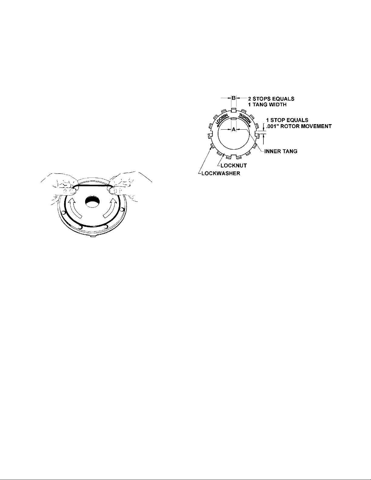
installation. Install a new head O-ring (72) in the groove
by laying the O-ring flat and starting in on one side of the
groove, stretching ahead with the fingers, as shown in
Figure 8.
9. Apply a thin coating of quality O-ring lubricant on the
inboard shaft to aid installation. Install the inboard head,
mechanical seal, and bearing as instructed in steps 2
through 6.
10. Rotate the shaft by hand to engage the seal drive tangs,
and to test for binding or tight spots. If the rotor does not
turn freely, lightly tap the rims of the heads with a soft
faced mallet until the correct position is found. Install all of
the remaining head capscrews for each head and
uniformly tighten, then torque to 25 lbs ft (34 Nm).
Figure 8 – Head O-Ring Installation
4. Install the head (20) on the outboard side of the cylinder.
Install and snug up four head capscrews (21) 90° apart.
5. Hand pack the ball bearing (24) with grease. Refer to
"Lubrication" in the Pump Maintenance Section for the
recommended grease.
6. Install the bearing into the head recess. The bearing balls
should face outward, with the grease shield inward.
Ensure the bearing is fully and squarely seated against
the mechanical seal.
7. Turn the pump cylinder around and begin assembly on
the opposite, inboard end.
8. Remove the vanes (14) and push rods (77) from the rotor
and shaft assembly. Inspect for wear and damage, and
replace as follows:
a. Partially install the non-driven end of the rotor and
shaft (13) into the open side of the pump cylinder.
b. Leave part of the rotor outside of the cylinder so that
the bottom vanes can be installed and held in place
as the push rods are installed in the push rod holes
of the rotor. Insert the new vanes into the rotor slots
with the rounded edges outward, and the vane relief
grooves facing TOWARDS the direction of rotation.
Refer to Figure 4 in “Vane Replacement.”
c. After the bottom vanes an d push rods are installed,
insert the rotor and shaft fully into the cylinder.
d. Install the remaining vanes into the top positions of
the rotor. Rotate the shaft by hand to engage the
drive tangs of the mechanical seal jacket in the
rotor slots.
Figure 9 – Locknut Assembly
11. LOCKNUT ADJUSTMENT –
GNX(H)2,GNX(H)2.5, and GNX(H)3 Models Only
It is important that the bearing locknuts (24A) and
lockwashers (24B) be installed and adjusted properly.
Overtightening locknuts can cause bearing failure or a
broken lockwasher tang. Loose locknuts will allow the
rotor to shift against the discs, causing wear. See Figure
a. On both ends of the pump shaft, install a lockwasher
(24B) with the tangs facing outward, followed by a
locknut (24A) with the tapered end inward. Ensure the
inner tang "A" of the lockwasher is located in the slot
in the shaft threads, bending it slightly, if necessary.
b. Tighten both locknuts to ensure that the bearings are
bottomed in the head recess. DO NOT overtighten
and bend or shear the lockwasher inner tang.
c. Loosen both locknuts one complete turn.
d. Tighten one locknut until a slight rotor drag is felt
when turning the shaft by hand.
e. Back off the nut the width of one lockwasher tang "B".
Secure the nut by bending the closest aligned
lockwasher tang into the slot in the locknut. The pump
should turn freely when rotated by hand.
f. Tighten the opposite locknut by hand until it is snug
against the bearing. Then, using a spanner wrench,
tighten the nut the width of one lockwasher tang “B”.
Tighten just past the desired tang, then back off the
nut to align the tang with the locknut slot. Secure the
nut by bending the aligned lockwasher tang into the
slot in the locknut. The pump should continue to turn
freely when rotated by hand.
g. To check adjustment, grasp the nut and washer with
fingers and rotate back and forth. If this cannot be
done, one or both locknuts are too tight and should be
alternately loosened one stop at a time 0.001"
(0.025mm). Begin by loosening the locknut adjusted
last.
101-C00 Page 12/20
Page 13
12. LOCK COLLAR INSTALLATION – GNX(H)4 Models
a. Slide the lock collar (24A) over the shaft and against
the bearing (24), with the counterbored side towards
the bearing
b. Push the collar (24A) forcibly against the bearing (24)
by hand, while tightening the two setscrews (24B).
Install and tighten the two jam nuts (24C) against the
collar
c. Rep eat this procedure on the opposite pump end.
After installing both lock collars, verify the shaft turns
freely when rotated by hand
13. Attach a new bearing cover gasket (26) and the outboard
bearing cover (27) to the outboard head. Install and
torque the bearing cover capscrews (28) to 15 ft-lbf (20
Nm).
14. Lightly oil Adapter O-ring (135B) and install on inboard
head.
15. Ensure the key (35) is installed on the pump shaft. With
the aid of a lifting device, slide the motor and gearbox
assembly towards the pump engaging gearbox shaft
receiver with the pump shaft.
16. Install the Adapter screws (20C) into the inboard head
and torque to 23 ft-lbf.
17. RELIEF VALVE ASSEMBLY
a. Insert the valve (9) into the relief valve bore of the
casing with the fluted end inward.
b. Install the relief valve spring (8) and spring guide (7)
against the valve.
c. Attach a new relief valve O-ring (10) and the valve
cover (4) on the cylinder.
d. Screw the relief valve adjusting screw (2) with locknut
(3) into the valve cover (4) until it makes contact with
the spring guide (7).
e. After the relief valve has been adjusted, tighten the
Locknut (3) and install the relief valve cap (1) and Oring (88).
NOTICE:
The relief valve setting MUST be tested and adjusted
more precisely before putting the pump into service.
Refer to "Relief Valve Setting and Adjustment"
Operation without guards in place can
cause serious personal injury, major
property damage, or death.
Do not operate
without guard in
place.
18. Reinstall coupling, shaft key, and coupling guards.
19. Refer to “Pre-Start Up Check List” and “Start Up
Procedures” sections of this manual prior to restarting
pump operation.
101-C00 Page 13/20
Page 14

GEAR REDUCER MAINTENANCE
NOTICE:
Detailed maintenance instructions for the gearbox
can be found at www.nord.com/docs. The
following are excerpts from those documents and
should be treated as reference only.
STORAGE
NOTICE:
For storage periods longer than 9 months, or for
storage in less than desirable conditions, please
consult NORD for recommendations.
Storage for up to 9 months is possible, so long as the
following conditions are observed:
Store the gear unit in its actual mounting position in
accordance with the specified oil fill-level, in a clean and
dry temperature controlled area. Avoid temperature
fluctuations within the range of 0°C and 40°C (32°F to
104°F) and avoid relative humidity conditions in excess
of 60%.
Protect all exposed or unpainted shaft and flange
surfaces with an anti-corrosion agent or grease.
Store in a location free from shock and vibration, to
avoid false brinelling of bearing elements and
raceways.
Whenever possible, rotate the shafts periodically, by
hand if necessary, to help prevent brinelling (bearing
damage) and to help keep the shaft seals pliable.
Avoid direct exposure to the sun or UV light and
aggressive or corrosive materials in the environment
(ozone, gases, solvents, acids, caustic solutions, salts,
radioactivity, etc.
Commissioning
Prior to gear unit start-up, complete the following:
Please check your gear unit for a vent and if applicable
to your product, remove the sealing plug to activate
NOTICE:
To prevent build-up of excessive pressure, sealed
vents must be activated as shown prior to gear
unit start up. Excessive pressure may cause
damage to internal gearbox components and
leakage.
Check the lubricant and be sure the gear unit is filled
with the proper oil type, to the proper level, as
determined by the mounting position.
Check the condition of all shaft seals and all assembled
flange gasket areas. If any change is detected in the
shape, color, hardness or permeability, or if any leaks
are detected, the corresponding shaft seals and/or
gaskets must be replaced.
Remove all anti-corrosive metal protectant from
otherwise bare metal surfaces. Follow product
manufacturer’s directions and warnings during surface
protection removal.
Check the resistance of all motor and brake windings to
verify the integrity of the winding insulation and inspect
all terminal box openings and wire connection areas to
verify that all components are dry and free of corrosion.
Long Term Storage
By taking special precautions, problems such as seal
leakage and reducer failure due to the lack of lubrication,
improper lubrication quantity, or contamination can be
avoided. The following precautions will protect gear
reducers during periods of extended storage:
Store the gear unit in its actual mounting position in
accordance with the specified oil fill-level, in a clean and
dry temperature controlled area. Avoid temperature
fluctuations within the range of 0°C and 40°C (32°F to
104°F) and avoid relative humidity conditions in excess
of 60%.
Fill the reducer full with oil that is compatible with the
product normally used or recommended during service.
Apply grease to all unpainted or unprotected shafts,
bores, keyways, flange surfaces, tapped holes, and to
the exterior of all oil seals.
Store in a location free from shock and vibration, to
avoid false brinelling of bearing elements and
raceways.
Once every few months rotate the input shaft
approximately 10-20 revolutions to redistribute the
weight of gears and shafts and to prevent brinnelling of
the bearings and drying of the seal track.
Avoid direct exposure to the sun or UV light and
aggressive or corrosive materials in the environment
(ozone, gases, solvents, acids, caustic solutions, salts,
radioactivity, etc.)
Commissioning After Long-Term Storage
Please check your gear unit for a vent and if applicable
to your product, remove the sealing plug to activate.
NOTICE:
To prevent build-up of excessive pressure, sealed vents
must be activated as shown prior to gear unit start up.
Excessive pressure may cause damage to internal
gearbox components and leakage.
Remove all anti-corrosive metal protectant from
otherwise bare metal surfaces. Follow product
manufacturer’s directions and warnings during surface
protection removal.
Drain the reducer and refill it with the proper type and
amount of lubricant.
Observe start-up and initial operation to make sure
there are no seal or gasket leaks, or unusual sounds,
vibration or heat rise during operation.
Check the resistance of all motor and brake windings to
verify the integrity of the winding insulation and inspect
all terminal box openings and wire connection areas to
verify that all components are dry and free of corrosion.
101-C00 Page 14/20
Page 15
Lubrication
V
V
Proper gearbox lubrication is essential in order to reduce
friction, heat, and component wear. Lubricants reduce heat
and wear by inserting a protective “fluid boundary” between
mating parts and preventing direct metal to metal contact.
Lubricants also help prevent corrosion and oxidation,
minimize foam, improve heat transfer, optimize reducer
efficiency, absorb shock loads and reduce noise. Most
NORD reducers are shipped from the factory with a predetermined oil fiIl level in accordance to the specified
reducer size and mounting position.
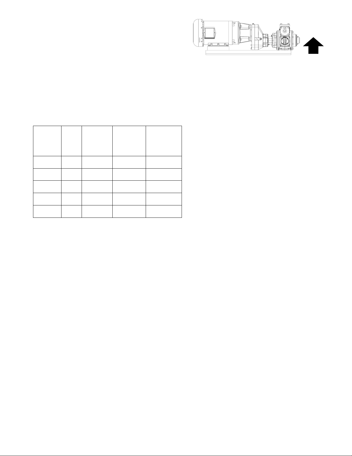
The standard orientation for the gearbox is shown in Figure
10. The gearbox is filled with the correct amount of oil and
is the correct configuration for this orientation. For any other
orientation, please consult the factory.
Lubrication Table
ISO
Viscosity
G220 PAO-
G220 PAO -31 to 140 Mobil
VG220 MINVG220 FG 23 to 104 Fuchs
VG460 PAO -31 to 176 Mobil SHC
*Standard Oil Shipped with Gearbox
Oil Formulation Codes:
MIN-EP - Mineral Oil with EP Additive
PAO - Synthetic Polyalphaolefin Oil
PAO-EP – Synthetic Polyaphoalefin Oil with EP Additive
FG - Food-Grade Oil
Oil
Type
EP
EP
Ambient
Temp
Range
(°F)
-31 to 140 Mobil SHC
32 to 104 Mobilgear
Brand Pump
Gear 220*
SHC630*
600XP220
FM220
634
Model:
Standard Oil
Shipped with
Gearbox
GNX(H)3,
GNX(H)4
GNX(H)2,
GNX(H)2.5
The “Ambient Temperature” is intended to be an
operation guideline based upon the typical properties of
all the lubricant. The viscosity and other properties of
the lubricant change based upon load, speed, ambient
conditions, and reducer operating temperatures. The
user should consult with their lubrication supplier &
NORD gear before considering changes in oil type or
viscosity.
Do not to mix different oils with different additive
packages or different base oil formulation types.
Polyglycol (PG) oils are not miscible with other oil types
and should never be mixed with mineral oil or
polyalphaolefin (PAO) synthetic oil.
UP
Figure 10 - Standard Gearbox Orientation
NOTICE:
To prevent reducer overheating, observe the
maximum operating oil temperature limits:
Mineral Oil: 176 – 180 °F
Synthetic Oil: 225 °F
In the following instances, please consult NORD for
specific recommendations:
o Gear units will operate in high ambient
temperature conditions exceeding 40°C
(104°F).
o Gear units will operate in cold ambient
temperature conditions approaching 0°C
(32°F) or lower.
o Lo wer than an ISO VG100 viscosity oil is
being considered for a cold-temperature
service.
o Fluid grease is required for lubricating the
gear unit.
Observe the general lubrication guidelines outlined
in user manual U10750.
NOTICE:
101-C00 Page 15/20
Page 16
PUMP TROUBLESHOOTING
Maintenance shall be performed by qualified technicians only,
following the appropriate procedures and warnings as presented in this manual.
Symptom Probable Cause
Pump Not Priming
Reduced Capacity
Noise
Damaged Vanes
Broken Shaft
Mechanical Seal
Leakage
1. Pump not wetted.
2. Worn vanes
3. Suction valve closed.
4. Air leaks in the suction line.
5. Strainer clogged.
6. Suction line or valves clogged or too restrictive.
7. Pump vapor-locked.
8. Pump speed too low for priming.
9. Relief valve partially open, worn or not seating properly.
1. Pump speed too low.
2. Suction valves not fully open.
3. Air leaks in the suction line.
4. Excessive restriction in the suction line (undersized piping, too many elbows & fittings, clogged
strainer, etc.).
5. Damaged or worn parts.
6. Excessive restriction in discharge line causing partial flow through the relief valve.
7. Relief Valve worn, set too low, or not seating properly.
8. Vanes installed incorrectly (see "Vane Replacement").
1. Excessive vacuum on the pump due to:
a. Undersized or restricted fittings in the suction line.
b. Pump speed too fast for the viscosity or volatility of the liquid.
c. Pump too far from fluid so urce.
2. Running the pump for extended periods with a closed discharge line.
3. Pump not securely mounted.
4. Bearings worn or damaged.
5. Vibration from improperly anchored piping.
6. Bent shaft, or drive coupling misaligned.
7. Excessively worn rotor.
8. Malfunctioning valve in the system.
9. Relief valve setting too low.
10. Damaged vanes (see following category).
11. Vanes installed incorrectly (see "Vane Replacement").
1. Foreign objects entering the pump.
2. Running the pump dry for extended periods of time.
3. Cavitation.
4. Viscosity too high for the vanes and/or the pump speed.
5. Incompatibility with the liquids pumped.
6. Excessive heat.
7. Worn or bent push rods, or worn push rod holes.
8. Settled or solidified material in the pump at start-up.
9. Hydraulic hammer - pressure spikes.
10. Vanes installed incorrectly (see "Vane Replacement").
1. Foreign objects entering the pump.
2. Viscosity too high for the pump speed
- EC Rotor & Shaft required for fluid viscosities over 20,000 SSU.
3. Relief valve not opening.
4. Hydraulic hammer - pressure spikes.
5. Pump/driver misalignment.
6. Excessively worn vanes or vane slots.
7. Settled or solidified material in the pump at start-up.
1. O-rings not compatible with the liquids pumped.
2. O-rings nicked, cut or twisted
3. Shaft at seal area damaged, worn or dirty.
4. Ball bearings overgreased.
5. Excessive cavitation.
6. Mechanical seal faces cracked, scratched, pitted or dirty.
101-C00 Page 16/20
NOTICE:
Page 17
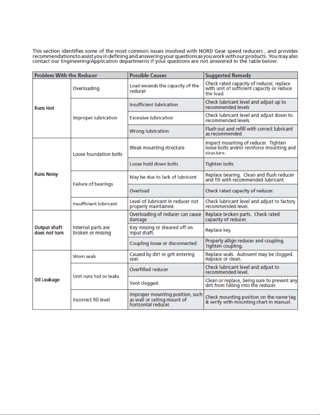
GEAR REDUCER TROUBLESHOOTING
NOTICE:
Maintenance shall be performed by qualified technicians only,
following the appropriate procedures and warnings as presented in this manual.
101-C00 Page 17/20
Page 18

This page intentionally left blank
101-C00 Page 18/20
Page 19

This page intentionally left blank
101-C00 Page 19/20
Page 20
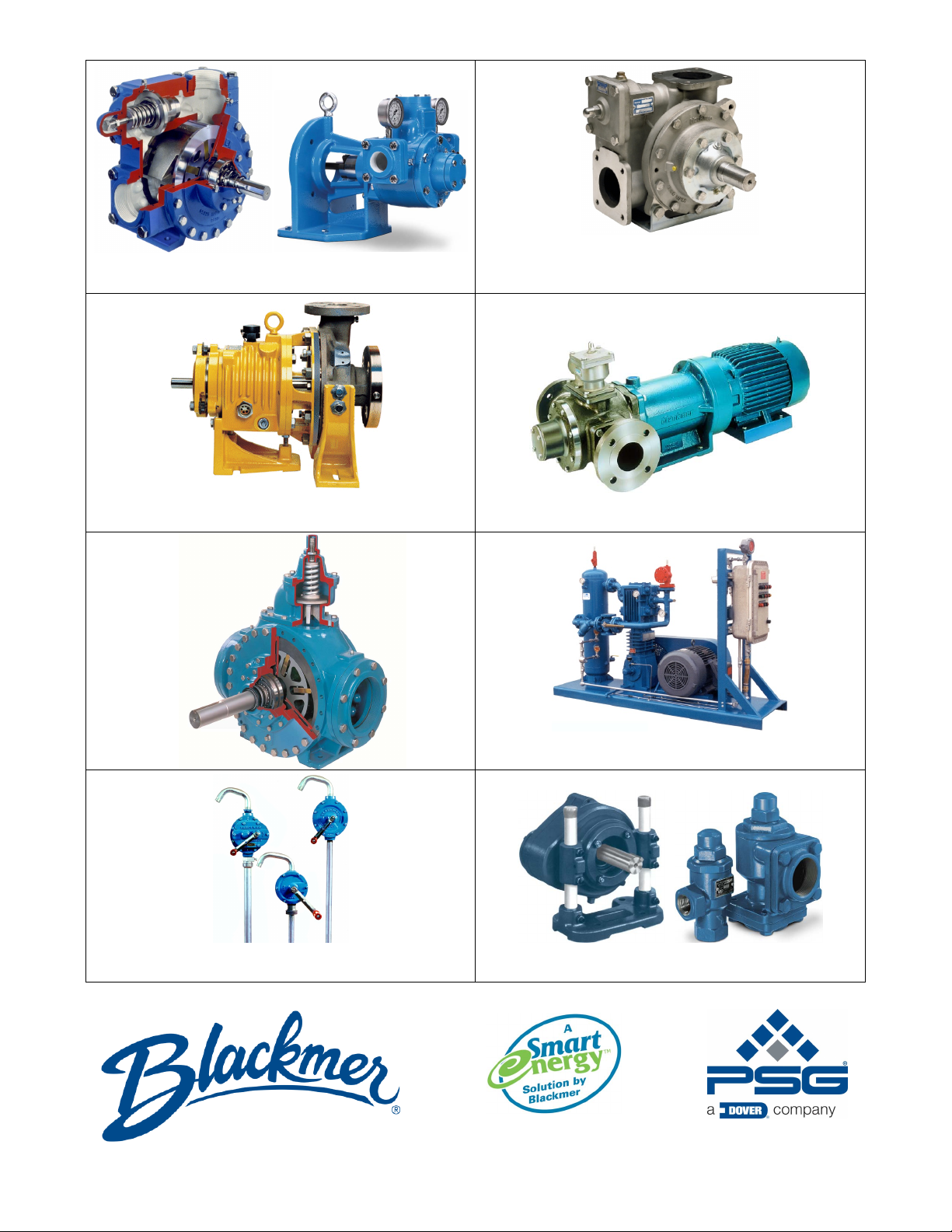
Sliding Vane Pumps: 5 to 2200 GPM
Refined Fuels, Liquefied Gases, Solvents,Process
®
System One
Centrifugal Pumps
10 to 7500 GPM; Process, Marine
L 6, 8 & 10”
HX
Sliding Vane Pumps
130 to 2,220 GPM
Refineries
Terminals
Barges
Ships
Stainless Steel Sliding Vane Pumps
1 to 265 GPM: Acids, Brines, Sugars, Syrups,
Beer, Beet Juice, Cider, Flavor Extracts, etc.
Magnetic Drive Pumps
Stainless Steel: 14 to 215 GPM
Reciprocating Gas Compressors
Liquefied Gas Transfer, Boosting, Vapor Recovery
Hand Opera
Dispensing, Transfer, In-line
ted Pumps
Accessories
Gear Reducers, Bypass Valves, Strainers
Visit www.blackmer.com for complete information on all Blackmer products
1809 Century Avenue, Grand Rapids, Michigan 49503-1530 U.S.A.
Telephone: (616) 241-1611 • Fax: (616) 241-3752
E-mail: [email protected] • Internet Address: www .blackmer.com
 Loading...