

Page 1
R
OPERATOR’S MANUAL
MANUAL DEL OPERADOR
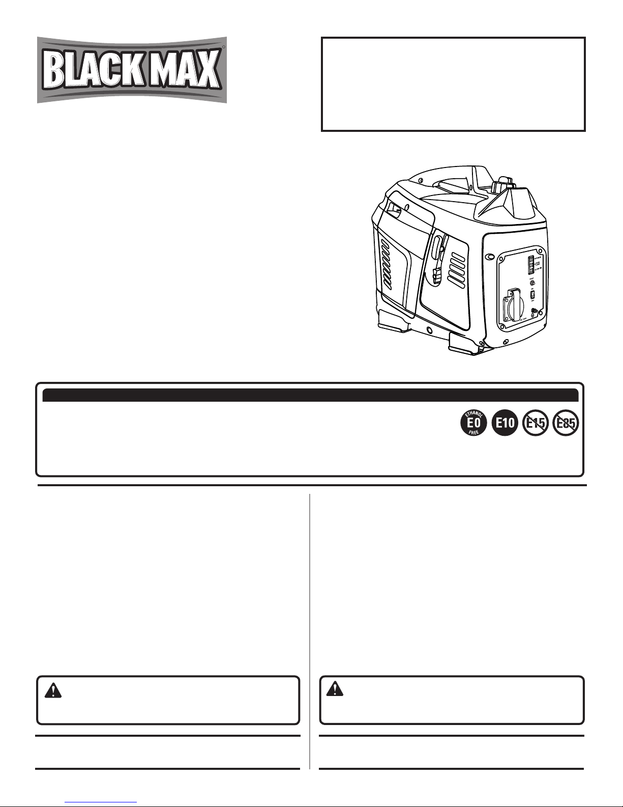
DIGITAL INVERTER GENERATOR
GENERADOR DEL INVERSOR DE DIGITACES
BMi1000
NEUTRAL FLOATING
NEUTRAL DE FLOTACIÓN
CUSTOMER SERVICE
1-800-726-5760
Mexico SERVICIO AL CLIENTE
1 800 843 1111
NOTICE AVISO
Do not use E15 or E85 fuel in this product. It is a violation of federal law and will damage the unit
and void your warranty. Only use unleaded gasoline containing up to 10% ethanol.
No utilice combustibles E15 o E85 con este producto. Esto constituye una violación a la ley
federal, dañará la unidad y anulará la garantía. Utilice únicamente gasolina sin plomo que
contiene hasta 10% de etanol.
TABLE OF CONTENTS
Important Safety Instructions ...............................................3-4
Specific Safety Rules .............................................................. 4
Symbols ...............................................................................5-7
Electrical ..............................................................................8-9
Features ................................................................................ 10
Assembly .............................................................................. 11
Operation .........................................................................11-14
Maintenance ....................................................................15-18
Troubleshooting ....................................................................19
Warranty ...........................................................................20-21
Parts Ordering / Service ...........................................Back Page
Instrucciones de seguridad importantes .............................. 3-4
Reglas de seguridad específicas .............................................4
Símbolos .............................................................................. 5-7
Aspectos eléctricos .............................................................. 8-9
Características .......................................................................10
Armado ...................................................................................11
Funcionamiento ................................................................ 11-14
Mantenimiento .................................................................. 15-18
Corrección de problemas .......................................................19
Garantía ............................................................................ 20-21
Pedidos de piezas / servicio ...............................Pág. posterior
ÍNDICE DE CONTENIDO
WARNING: To reduce the risk of injury, the user must
read and understand the operator’s manual before using this
product.
SAVE THIS MANUAL FOR
FUTURE REFERENCE
ADVERTENCIA: Para reducir el riesgo de lesiones, el
usuario debe leer y comprender el manual del operador antes
de usar este producto.
GUARDE ESTE MANUAL
PARA FUTURAS CONSULTAS
Page 2

See this fold-out section for all of the figures
referenced in the operator’s manual.
Consulte esta sección desplegable
para ver todas las figuras a las que se hace
referencia en el manual del operador.
ii
Page 3
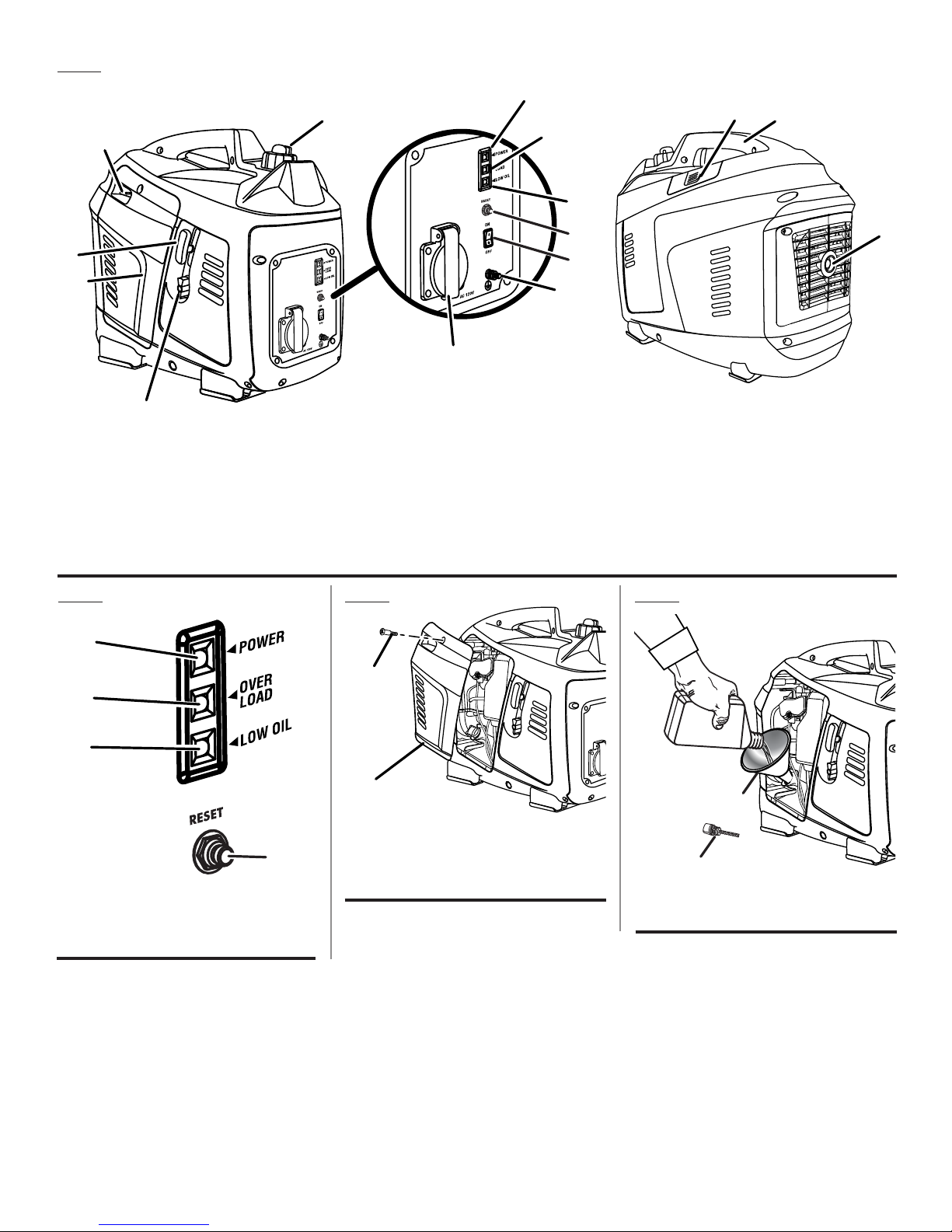
Fig. 1
C
B
L
E
D
K
M
N
J
I
O
H
G
F
A
A - On/off switch/fuel valve (interruptor de
encendido y apagado/ válvula de combustible)
B - Engine maintenance cover (cubierta de
mantenimiento del motor)
C - Starter grip and rope (mango del arrancador
y cuerda)
D - Choke lever (palanca del anegador)
E - Vented fuel cap (tapa del tanque ventilación)
F - 120 volt AC 15 amp receptacle (120 V de ca
15 A receptáculo)
G - Ground terminal (terminal de conexión a
tierra)
H - Auto idle switch (interruptor de ralentí
automático)
I - Reset button (botón de reajuste)
Fig. 2 Fig. 4Fig. 3
A
B
B
C
A
D
A - Power indicator (indicador de encendido)
B - Overload indicator (indicador de sobrecarga)
C - Low oil indicator (luz de bajo nivel de aceite)
D - Reset button (botón de reajuste)
A - Engine maintenance cover (cubierta de
mantenimiento del motor)
B - Screw (tornillo)
J - Low oil indicator (luz de bajo nivel de aceite)
K
- Overload indicator (indicador de sobrecarga)
L - Power indicator (indicador de potencia)
M
- Spark plug cover (cubierta de la bujía)
N - Carry handle (mango de acarreo)
O- Muffler with spark arrestor screen (silenciador
con pantalla parachispas)
B
A
A - Oil cap/dipstick (tapa de relleno de aceite/
varilla medidora de aceite)
B - Funnel (embudo)
iii
Page 4
T
H
R
OT
T
LE
S
M
A
R
T
O
F
F
O
N
1
2
0
V
.
C
O
V
E
R
L
OA
D
I
N
D
I
C
A
T
O
R
:
12
V
O
U
T
P
U
T
L
A
L
A
R
M
Fig. 5
Fig. 8
Fig. 11
C
A
B
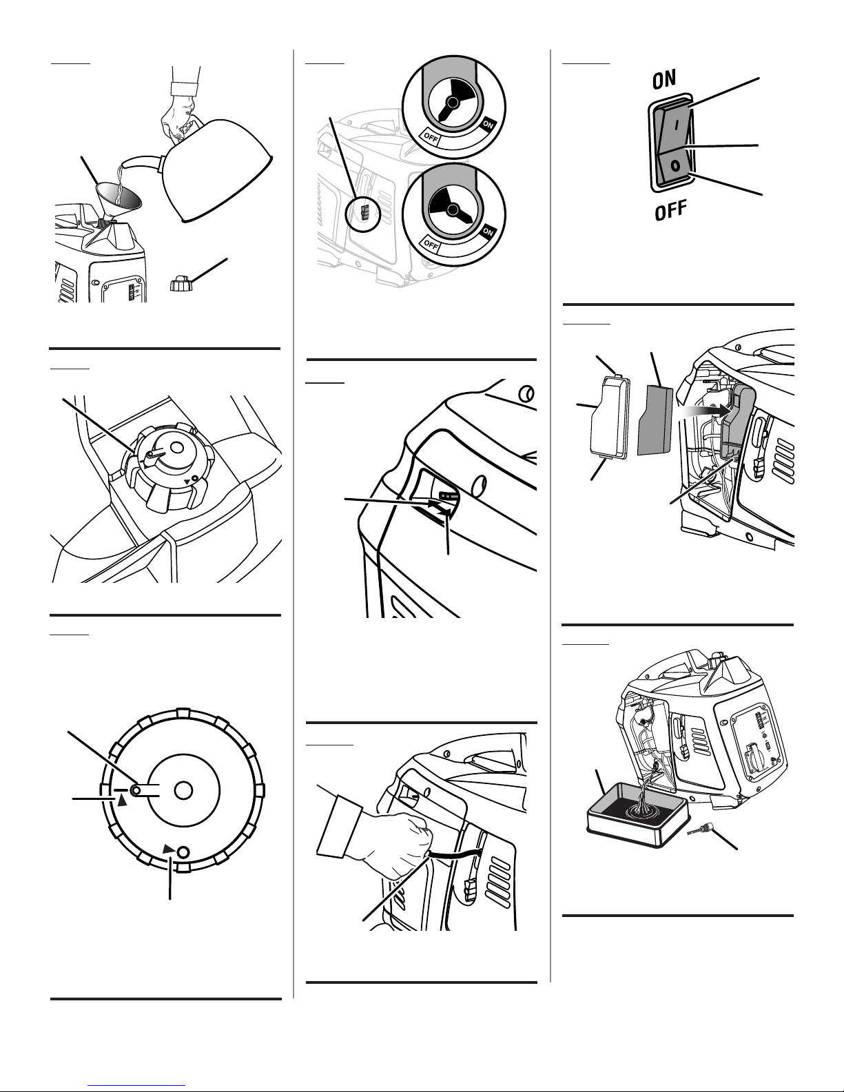
A - Funnel (embudo)
B - Vented fuel cap (tapa del tanque ventilación)
Fig. 6
A
A
B
C
A - On/off switch/fuel valve (interruptor de
encendido y apagado/válvula de combustible)
B - Off (apagado)
C - On (encendido)
Fig. 9
B
A
B
A - Auto idle switch (interruptor de ralentí
automático)
B - Off (apagado)
C - On (encendido)
Fig. 12
B
A
B
C
D
A - Vented fuel cap (tapa del tanque ventilación)
Fig. 7
Top View
Vista superior
A
B
C
A - Fuel cap lever (palanca de la tapa de
combustible)
B - Open position (I) [posición abierto (I)]
C - Closed/storage position (O) [posición
cerrado/almacenamiento (O)]
A
A - Move choke lever right to start (desplace
derecha de la palanca del anegador para
arrancar)
B - Move choke lever left to run (desplace
izquierda la palanca del anegador para poner
en marcha)
Fig. 10
A
A - Starter grip and rope (mango del arrancador
y cuerda)
A - Air filter cover (tapa del filtro de aire)
B - Tab (orejeta)
C - Air filter (filtro de aire)
D - Slot (ranura)
Fig. 13
B
A
A - Oil cap/dipstick (tapa de relleno de aceite/
varilla medidora de aceite)
B - Container (recipiente)
iv
Page 5
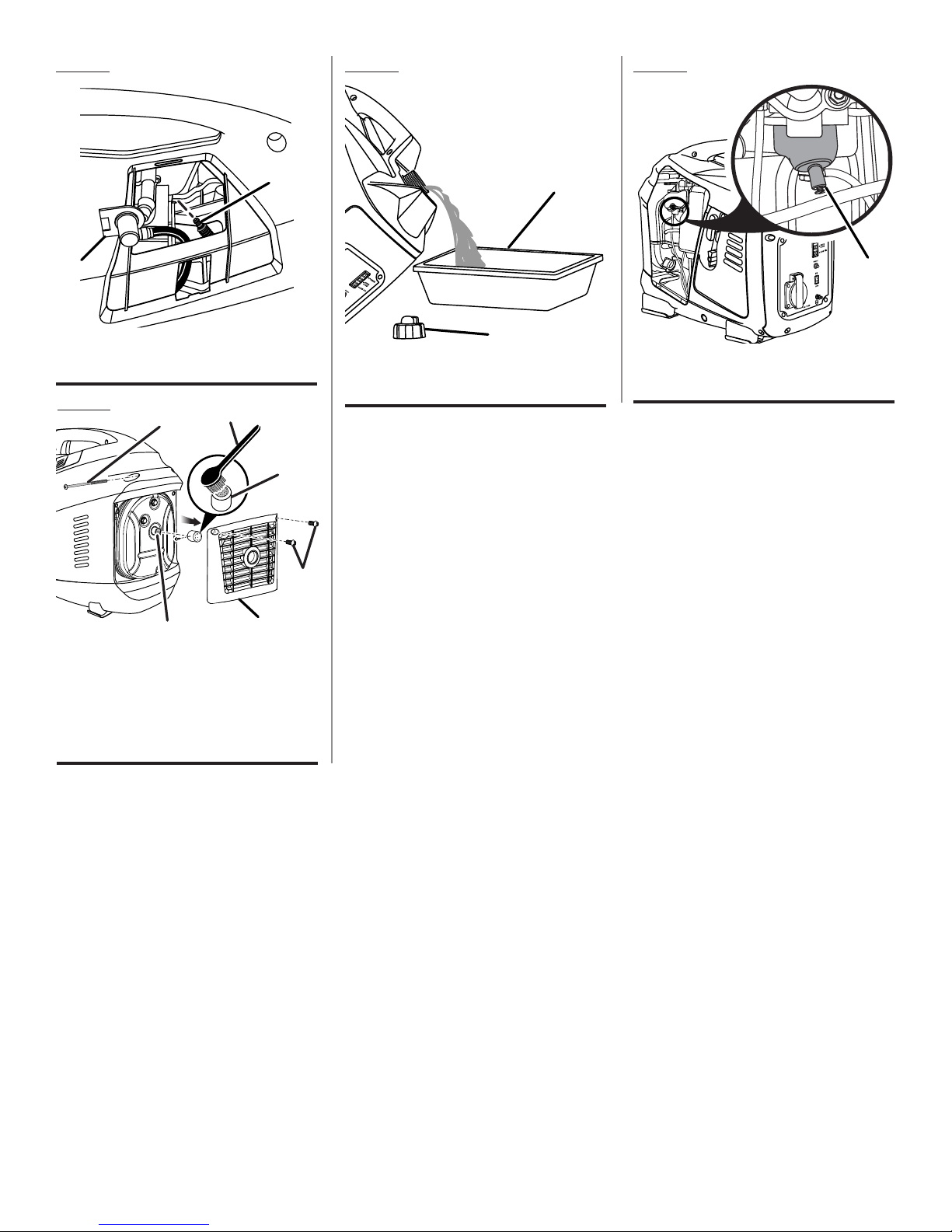
Fig. 14
Fig. 16 Fig. 17
A
A - Spark plug cap (tapa de la bujía)
B - Spark plug (bujía)
Fig. 15
F
D
B
B
B
A
A
A - Vented fuel cap (tapa del tanque ventilación)
B - Container (recipiente)
A - Carburetor drain screw (tornillo de drenaje
del caburador)
C
A
E
A - Screws (tornillos)
B - Muffler outlet (recubrimiento del silenciador)
C - Spark arrestor (parachispas)
D - Wire brush (cepillo de alambre)
E - Rear panel (panel posterior)
F - Long screw (tornillo largo)
v
Page 6
To register your Black Max product,
please visit: www.blackmaxtools.com
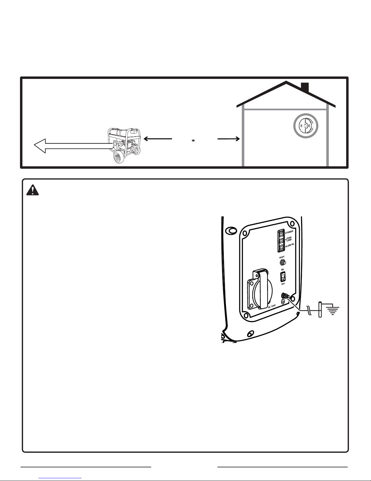
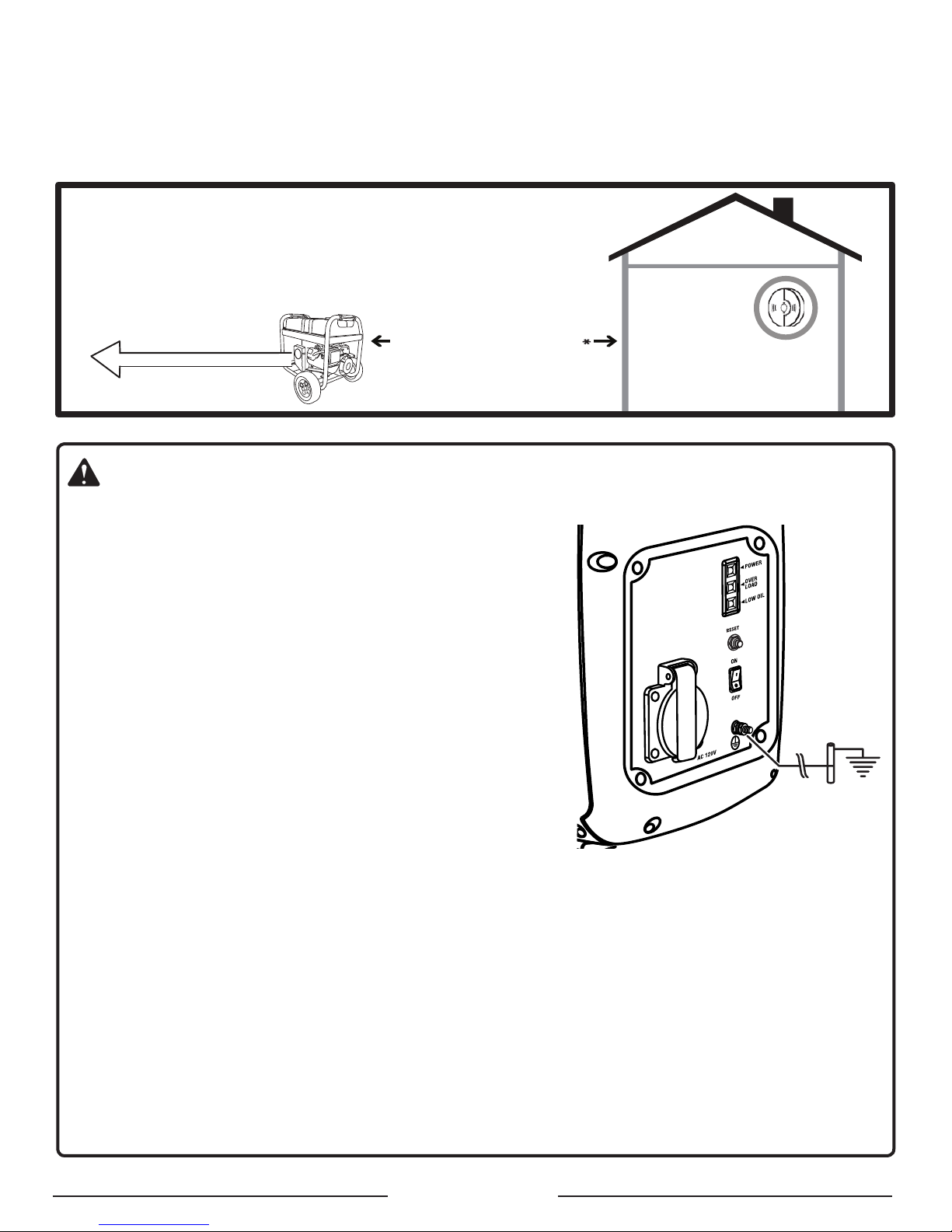
LOCATE GENERATOR AT LEAST 20 FT.* AWAY TO REDUCE THE
RISK OF CARBON MONOXIDE GETTING INSIDE THE HOME
* Minimum distance as recommended by U.S. Department of Health and Human
Services Centers for Disease Control and Prevention (www.cdc.gov/co). Your specific
home and/or wind conditions may require additional distance.
CO Detector
in Living Areas
Exhaust (CO)
Direct exhaust AWAY
from all windows, doors,
and vents.
KEEP AT LEAST
20 FT. AWAY
Only use OUTSIDE and
FAR AWAY from windows,
doors, and vents.
WARNING:
GROUNDING THE GENERATOR
If this generator will be used only with cord and plug-connected
equipment, National Electric Code does not require that the unit be
grounded. However, other methods of using the generator may require
grounding to reduce the risk of shock or electrocution. Consult a qualified electrician, electrical inspector, or local agency having jurisdiction
for local codes or ordinances to find out if grounding is needed in your
situation before using the generator.
When grounding is required, the nut and ground terminal on the frame
are used to connect the generator to a suitable ground source. The
ground path should be made with #8 size wire. Connect the terminal of
the ground wire between the lock washer and the nut, and tighten the
nut fully. Connect the other end of the wire securely to a suitable ground
source that is in contact with the soil for a minimum distance of 8 ft.
The National Electric Code contains several practical ways in which to
establish a good ground source. If a steel or iron rod is used, it should
be at least 5/8 in. diameter, and if a nonferrous rod is used, it should
be at least 1/2 in. diameter and be listed as material for grounding. If
a rock bottom is encountered before reaching a depth of 8 ft., drive
the ground rod in at an angle of up to 45°. If the rock bottom is again encountered, the rod can be buried in a trench
that is at least 30 in. deep. In all cases, the upper end of the grounding rod should either be flush with (or below) the
ground or must be otherwise protected from physical damage.
All electrical tools and appliances operated from this generator must be properly grounded by use of a third wire or
be “Double Insulated.”
It is recommended to:
1. Use electrical devices with 3-prong grounded plugs.
2. Use an extension cord intended for outdoor use with a 3-pole receptacle and a 3-prong plug at opposite ends to
ensure continuity of the ground protection from the generator to the appliance.
Check and adhere to all applicable federal, state, and local regulations relating to grounding specifications. Consult a
qualified electrician or service personnel if the grounding instructions are not completely understood or if in doubt as
to whether the generator is properly grounded.
Page 2 — English
Page 7
IMPORTANT SAFETY INSTRUCTIONS
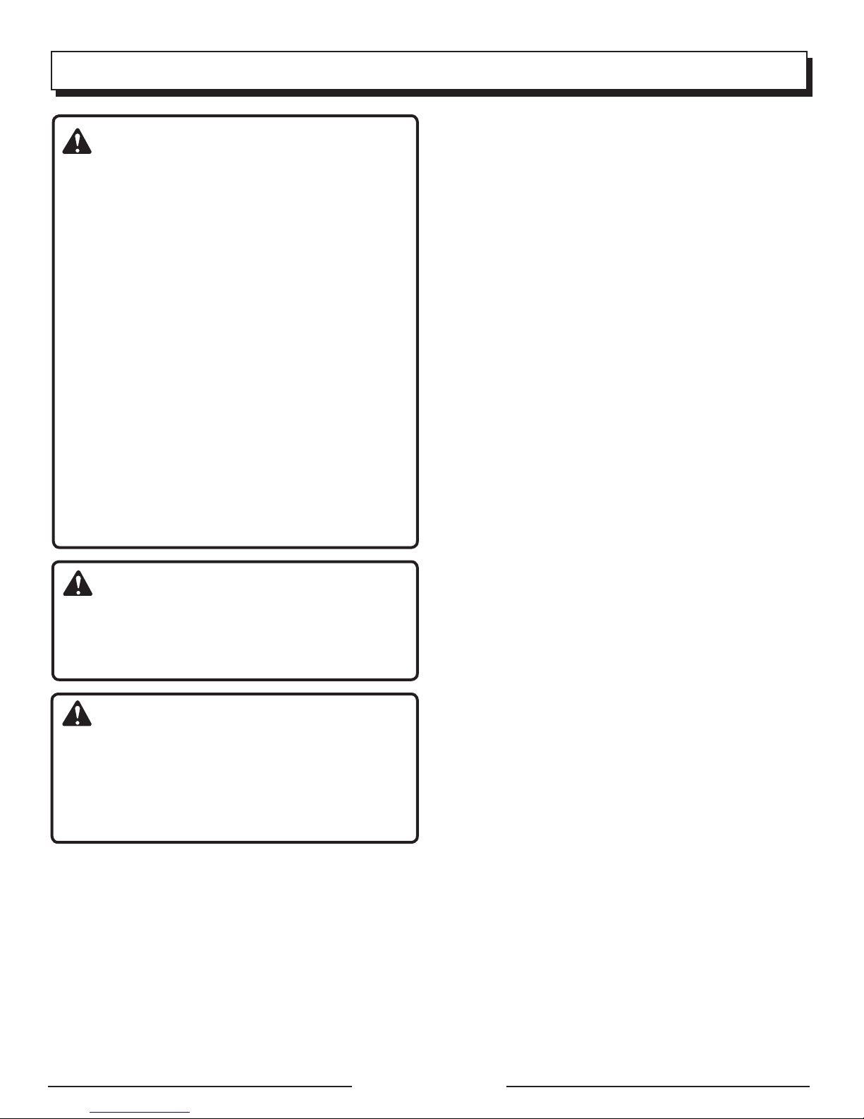
DANGER:
Carbon Monoxide. Using a generator indoors CAN KILL
YOU IN MINUTES.
Generator exhaust contains high levels of carbon
monoxide (CO), a poisonous gas you cannot see or smell.
If you can smell the generator exhaust, you are breathing
CO. But even if you cannot smell the exhaust, you could
be breathing CO.
Never use a generator inside homes, garages,
crawlspaces, or other partly enclosed areas. Deadly
levels of carbon monoxide can build up in these areas.
Using a fan or opening windows and doors does NOT
supply enough fresh air.
ONLY use a generator outdoors and far away from
open windows, doors, and vents. These openings
can pull in generator exhaust.
Even when you use a generator correctly, CO may
leak into the home. ALWAYS use a battery-powered or
battery-backup CO alarm in the home.
If you start to feel sick, dizzy, or weak after the generator
has been running, move to fresh air RIGHT AWAY. See
a doctor. You could have carbon monoxide poisoning.
WARNING:
Read and understand all instructions. Failure to follow
all instructions listed below could result in electrocution,
fire, and/or carbon monoxide poisoning, which can cause
death or serious injury.
WARNING:
In some applications, National Electric Code requires
generator to be grounded to an approved earth ground.
Before using the ground terminal, consult a qualified
electrician, electrical inspector, or local agency having
jurisdiction for local codes or ordinances that apply to
the intended use of the generator.
SAVE THESE INSTRUCTIONS
This manual contains important instructions for this product
that should be followed during installation and maintenance
of the generator.
Do not connect to a building’s electrical system unless
the generator and transfer switch have been properly
installed and the electrical output has been verified by
a qualified electrician. The connection must isolate the
generator power from utility power and must comply with
all applicable laws and electrical codes.
Do not allow children or untrained individuals to use this
unit.
Do not start or operate the engine in a confined space,
building, near open windows, or in other unventilated space
where dangerous carbon monoxide fumes can collect.
Carbon monoxide, a colorless, odorless, and extremely
dangerous gas, can cause unconsciousness or death.
Keep all bystanders, children, and pets at least 10 feet
away.
Wear sturdy and dry shoes or boots. Do not operate while
barefoot.
Do not operate generator when you are tired or under the
influence of drugs, alcohol, or medication.
Keep all parts of your body away from any moving parts
and all hot surfaces of the unit.
Do not touch bare wire or receptacles.
Do not use generator with electrical cords which are worn,
frayed, bare, or otherwise damaged.
Before storing, allow the engine to cool for 30 minutes
and drain fuel from the unit.
Do not operate or store the generator in rain, snow, or
wet weather.
Store the generator in a well-ventilated area with the fuel
tank empty. Fuel should not be stored near the generator.
Empty fuel tank, turn the on/off switch/fuel valve to OFF
and restrain the unit from moving before transporting in
a vehicle.
Provide a plastic sheet or absorbent pad below the
generator to catch any drips of fuel or lubricant when
transporting.
To reduce the risk of fire and burn injury, handle fuel with
care. It is highly flammable.
Do not smoke while handling fuel.
Store fuel in a container approved for gasoline.
Position the unit on level ground, stop engine, and allow
to cool for five minutes before refueling.
Loosen fuel cap slowly to release pressure and to keep
fuel from escaping around the cap.
Tighten the fuel cap securely after refueling.
Wipe spilled fuel from the unit.
Never attempt to burn off spilled fuel under any
circumstances.
Generators vibrate in normal use. During and after the
use of the generator, inspect the generator as well as
extension cords and power supply cords connected to
it for damage resulting from vibration. Have damaged
items repaired or replaced as necessary. Do not use plugs
or cords that show signs of damage such as broken or
cracked insulation or damaged blades.
For power outages, permanently installed stationary
generators are better suited for providing back-up power
to the home. Even a properly connected portable generator
can become overloaded. This may result in overheating
or stressing the generator components, possibly leading
to generator failure.
Page 3 — English
Page 8
IMPORTANT SAFETY INSTRUCTIONS
Use only recommended or equivalent replacement parts
and accessories and follow instructions in the Maintenance
section of this manual. Use of any other parts or failure
to follow maintenance instructions may create a risk of
shock or injury.
SPECIFIC SAFETY RULES
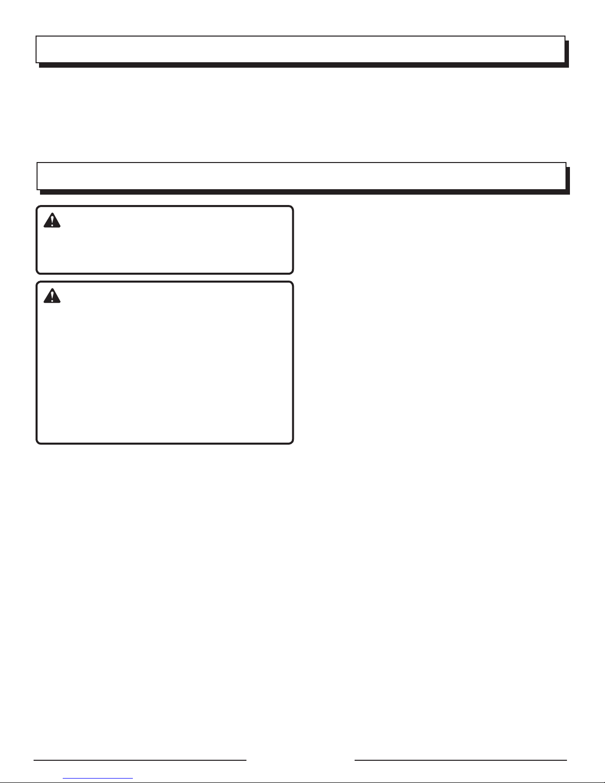
DANGER:
Risk of fire and serious burns: Never remove fuel cap
when unit is running. Shut off engine and allow the unit
to cool at least five minutes. Remove cap slowly.
WARNING:
When this generator is used to supply a building
wiring system: generator must be installed by a
qualified electrician and connected to a transfer switch
as a separately derived system in accordance with
NFPA 70, National Electrical Code. The generator shall
be connected through a transfer switch that switches
all conductors other than the equipment grounding
conductor. The frame of the generator shall be connected
to an approved grounding electrode. Failure to isolate the
generator from power utility can result in death or injury
to electric utility workers.
Do not use this generator to provide power for emergency
medical equipment or life support devices.
This generator has a neutral floating condition. This means
the neutral conductor is not electrically connected to the
frame of the machine.
Always use a battery-powered carbon monoxide detector
when running the generator. If you begin to feel sick,
dizzy, or weak while using the generator, shut it off and
get to fresh air immediately. See a doctor. You may have
carbon monoxide poisoning.
Place the generator on a flat, stable surface with a slope
of no more than 4°.
Operate outdoors in a well-ventilated, well-lit area isolated
from working areas to avoid noise interference.
Operating the generator in wet conditions could result in
electrocution. Keep the unit dry.
Maintain the unit per maintenance instructions in this
Operator’s Manual.
Inspect the unit before each use for loose fasteners, fuel
leaks, etc. Replace damaged parts.
Keep the generator a minimum of 3 feet away from all
types of combustible material.
Do not operate generator near hazardous material.
Do not operate generator at a gas or natural gas filling
station.
Do not touch the muffler or cylinder during or immediately
after use; they are HOT and will cause burn injury.
Do not allow the generator’s gas tank to overflow when
filling. Fill to 1 in. below the top neck of the gasoline tank
to allow for fuel expansion. Do not cover the fuel tank cap
when the engine is running. Covering the fuel tank cap
during use may cause engine failure and/or damage to
the tool.
Do not smoke when filling the generator with gasoline.
Shut down the engine and allow to cool for five minutes
before adding gasoline or lubricant to the generator.
Do not remove the oil dipstick or the fuel tank cap when
the engine is running.
Pay close attention to all safety labels located on the
generator.
Keep children a minimum of 10 feet away from the
generator at all times.
The unit operates best in temperatures between 23°F and
104°F with a relative humidity of 90% or less.
Operating voltage and frequency requirement of all
electronic equipment should be checked prior to plugging
them into this generator. Damage may result if the
equipment is not designed to operate within a +/- 10%
voltage variation, and +/- 3 hz frequency variation from
the generator name plate ratings.
For outdoor use only.
Save these instructions. Refer to them frequently and use
them to instruct others who may use this product. If you
loan someone this product, loan them these instructions
also.
Page 4 — English
Page 9
SYMBOLS
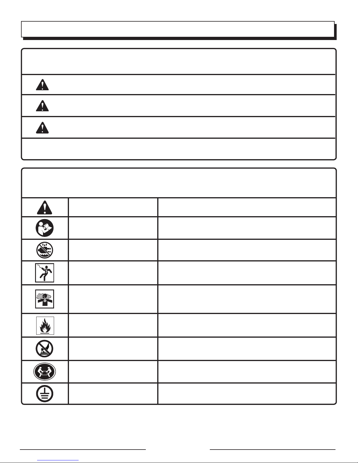
The following signal words and meanings are intended to explain the levels of risk associated with this product.
SYMBOL SIGNAL MEANING
DANGER:
WARNING:
CAUTION:
NOTICE:
Some of the following symbols may be used on this product. Please study them and learn their meaning. Proper
interpretation of these symbols will allow you to operate the product better and safer.
Indicates an imminently hazardous situation, which, if not avoided, will result
in death or serious injury.
Indicates a potentially hazardous situation, which, if not avoided, could result
in death or serious injury.
Indicates a potentially hazardous situation, which, if not avoided, may result in
minor or moderate injury.
(Without Safety Alert Symbol) Indicates important information not related to an
injury hazard, such as a situation that may result in property damage.
SYMBOL NAME DESIGNATION/EXPLANATION
Safety Alert Indicates a potential personal injury hazard.
Read Operator’s Manual
Wet Conditions Alert Do not expose to rain or use in damp locations.
To reduce the risk of injury, user must read and understand
operator’s manual before using this product.
Electric Shock
Toxic Fumes
Fire/Explosion
Hot Surface and Exhaust
Gases
Lifting Hazard
Ground
Failure to use in dry conditions and to observe safe practices can
result in electric shock.
Running generator gives off carbon monoxide, an odorless, colorless, poison gas. Breathing carbon monoxide can cause nausea,
fainting, or death.
Fuel and its vapors are extremely flammable and explosive. Fire
or explosion can cause severe burns or death.
To reduce the risk of injury or damage, avoid contact with any
hot surface and do not place any body parts in the path of hot
exhaust gases.
To reduce the risk of serious injury, avoid attempting to lift the
generator alone.
Consult with local electrician to determine grounding requirements
before operation.
Page 5 — English
Page 10
SYMBOLS
Some of the following symbols may be used on this product. Please study them and learn their meaning. Proper
interpretation of these symbols will allow you to operate the product better and safer.
SYMBOL NAME DESIGNATION/EXPLANATION
V Volts Voltage
A Amperes Current
Hz Hertz Frequency (cycles per second)
W Watt Power
hrs Hours Time
gal Gallon Volume
qt Quart Volume
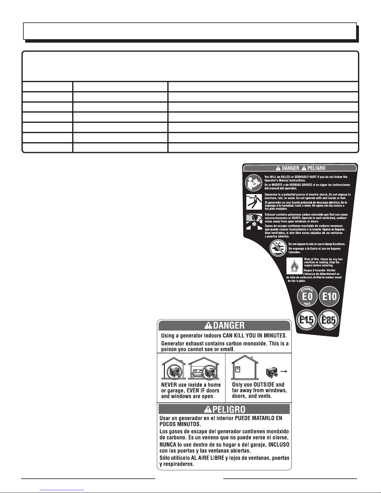
SAFETY LABELS
The information below can be found on the generator. For your safety, please
study and understand all of the labels before starting the generator.
If any of the labels come off the unit or become hard to read, contact customer
service or a qualified service center for replacement.
You WILL be KILLED or SERIOUSLY HURT if you do not follow the Operator’s
Manual instructions.
Risk of Fire. Do not add fuel while the product is operating.
Generator is a potential source of electric shock. Do not expose to moisture,
rain, or snow. Do not operate with wet hands or feet.
Exhaust contains poisonous carbon monoxide gas that can cause
unconsciousness or DEATH. Operate in well-ventilated, outdoor areas away
from open windows or doors.
Do not expose to rain or use in damp locations.
Using a generator indoors CAN KILL YOU IN MINUTES. Generator exhaust
contains carbon monoxide. This is a poison you cannot see or smell.
NEVER use inside a home or garage, EVEN IF doors and windows are open.
Only use OUTSIDE and far away from windows, doors, and vents.
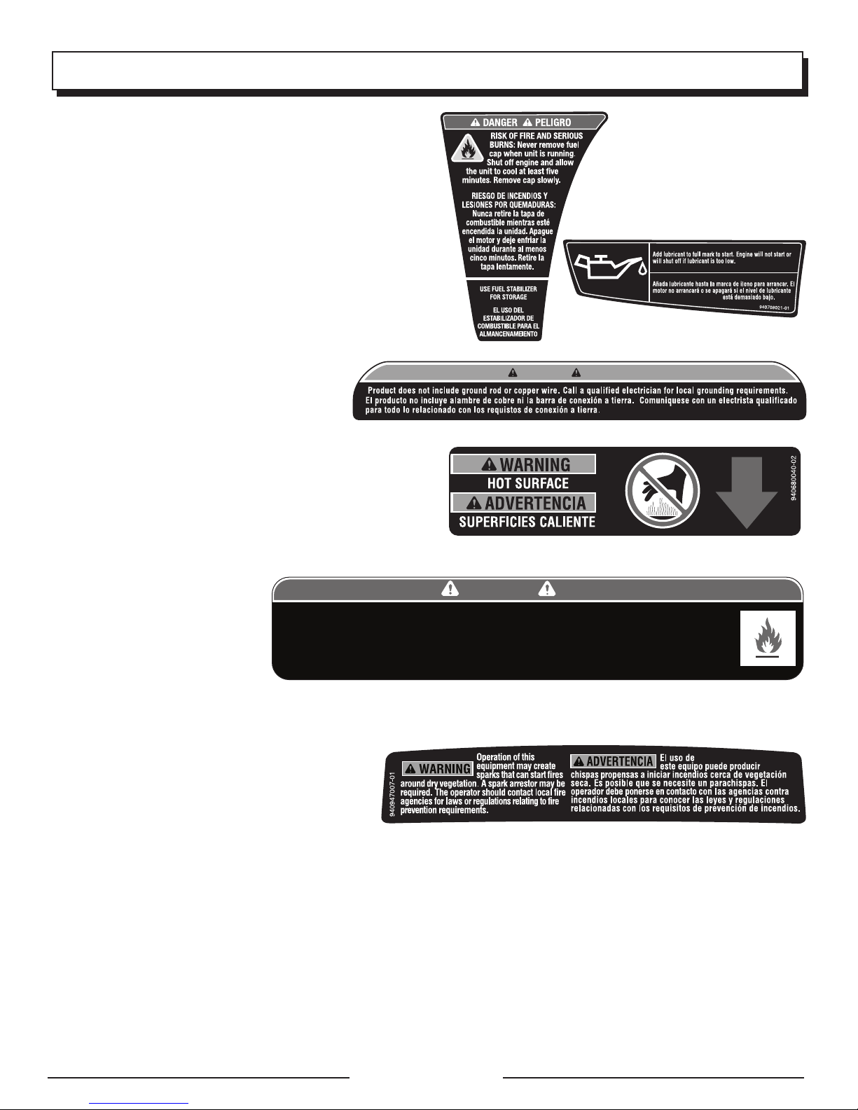
FUEL WARNING
No smoking when filling with gasoline. Do not
overfill. Full level is 1 in. below the top of the fuel
neck. Stop the engine for five minutes before
refueling to avoid the heat from the muffler
igniting fuel vapors.
Page 6 — English
Page 11
SYMBOLS
FUEL WARNING
Never remove fuel cap when unit is running. Shut off engine
and allow the unit to cool at least five minutes. Remove cap
slowly to release any pressure built up in the fuel system
and to avoid the heat from the muffler igniting fuel vapors.
ENGINE LUBRICANT WARNING
You must add lubricant before first operating the generator.
Always check the lubricant level before each operation. The
lubricant level should always register between the hatched
areas on the dipstick. The unit is equipped with a sensor
which will automatically shut off the engine if the lubricant
level falls below a safe limit.
GROUNDING WARNING
This generator does not include a ground rod or
copper wire. Call a qualified electrician for local
grounding requirements.
HOT SURFACE WARNING
Do not touch the muffler or aluminum cylinder of the engine.
They are very HOT and will cause severe burns. Don’t put
body parts or any flammable or combustible materials in the
direct path of the exhaust.
CLEARANCE WARNING
While operating and storing, keep
at least 3 feet of clearance on all
sides of this product, including
overhead. Allow a minimum of
30 minutes of “cool down” time
before storage. Heat created by
muffler and exhaust gases could
Risk of Fire. Keep all objects at least 3 feet away from this machine. Heat from Muffler and Exhaust gases
can ignite combustible objects.
Riesgo de incendio. Mantener todos los objetos a una distancia mínima de 91,4 cm (3 pies) de esta
máquina. El calor de los gases del silenciador y el escape pueden prender fuego a objetos combustibles.
940974090-03
be hot enough to cause serious
burns and/or ignite combustible
objects.
SPARK ARRESTOR
Operation of this equipment may create sparks
that can start fires around dry vegetation. A spark
arrestor may be required. The operator should
contact local fire agencies for laws or regulations
relating to fire prevention requirements.
WARNING
ADVERTENCIA
DANGER PELIGRO
Page 7 — English
Page 12
ELECTRICAL
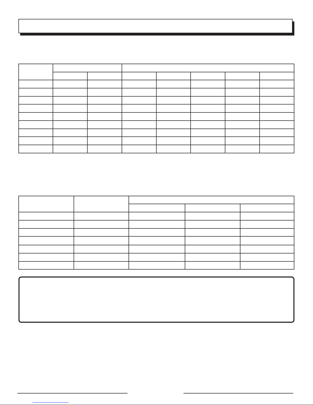
EXTENSION CORD CABLE SIZE
Refer to the table below to ensure the cable size of the extension cords you use are capable of carrying the required load.
Inadequate size cables can cause a voltage drop, which can damage the appliance and overheat the cord.
Current in
Amperes
2.5 300 600 1000 ft. 600 ft. 375 ft. 250 ft.
5 600 1200 500 ft. 300 ft. 200 ft. 125 ft.
7.5 900 1800 350 ft. 200 ft. 125 ft. 100 ft.
10 1200 2400 250 ft. 150 ft. 100 ft. 50 ft.
15 1800 3600 150 ft. 100 ft. 65 ft.
20 2400 4800 175 ft. 125 ft. 75 ft.
25 3000 6000 150 ft. 100 ft.
30 3600 7200 125 ft. 65 ft.
40 4800 9600 90 ft.
Load in Watts Maximum Allowable Cord Length
At 120V At 240V #8 Wire #10 Wire #12 Wire #14 Wire #16 Wire
ELECTRIC MOTOR LOADS
It is characteristic of common electric motors in normal operation to draw up to six times their running current while starting.
This table may be used to estimate the watts required to start electric motors; however, if an electric motor fails to start or
reach running speed, turn off the appliance or tool immediately to avoid equipment damage. Always check the requirements
of the tool or appliance being used compared to the rated output of the generator.
Motor Size (H.P.) Running Watts
1/8 275 N/A 850 1200
1/6 275 600 850 2050
1/4 400 800 1050 2400
1/3 450 950 1350 2700
1/2 600 1000 1800 3600
3/4 850 1200 2600 —
1 1100
Universal Capacitor Split Phase
N/A
Watts Required to Start Motor
3300 —
NOTICE:
Operating voltage and frequency requirement of all electronic equipment should be checked prior to plugging them
into this generator. Damage may result if the equipment is not designed to operate within a +/- 10% voltage variation,
and +/- 3 hz frequency variation from the generator name plate ratings. To avoid damage, always have an additional
load plugged into the generator if solid state equipment (such as a television set) is used. A power line conditioner is
recommended for some solid state applications.
Page 8 — English
Page 13
ELECTRICAL
GENERATOR CAPACITY
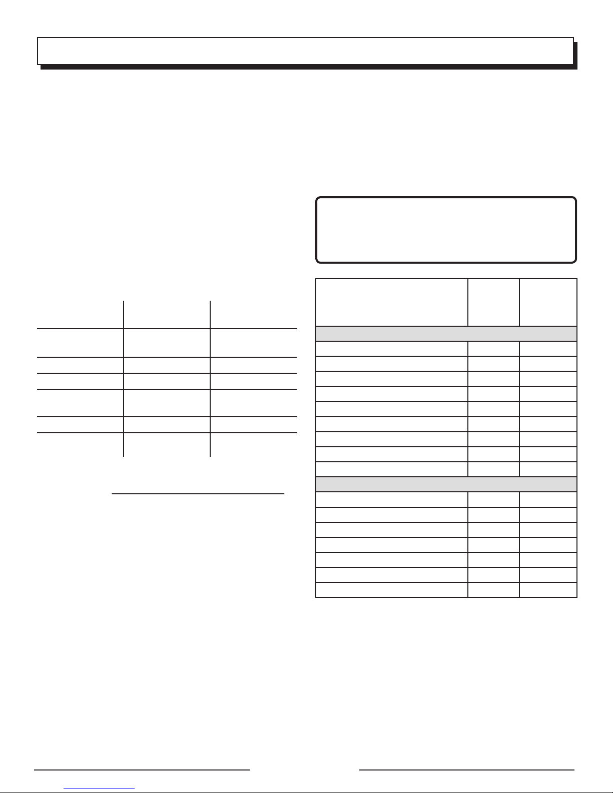
Make sure the generator can supply enough continuous (running) and surge (starting) watts for the items you will power
at the same time. Follow these simple steps.
1. Select the items you will power at the same time.
2. Total the continuous (running) watts of these items. This
is the amount of power the generator must produce to
keep the items running. See the wattage reference chart
at right.
3. Estimate how many surge (starting) watts you will need.
Surge wattage is the short burst of power needed to
start electric motor-driven tools or appliances such as a
circular saw or refrigerator. Because not all motors start
at the same time, total surge watts can be estimated by
adding only the item(s) with the highest additional surge
watts to the total rated watts from step 2.
Example:
Tool or Appliance
Running
Watts*
Starting
Watts*
Refrigerator 700 1350
Portable Fan 40 120
Laptop 250 250
46 in. Flat Panel
190 190
Television
Light (75 Watts) 75 75
1255 Total
Running Watts
1350 Highest
Starting Watts
Total Running Watts 1255
Highest Starting Watts + 1350
Total Starting Watts Required 2605
POWER MANAGEMENT
To prolong the life of the generator and attached devices,
it is important to take care when adding electrical loads to
the generator. There should be nothing connected to the
generator outlets before starting its engine. The correct and
safe way to manage generator power is to sequentially add
loads as follows:
1. With nothing connected to the generator, start the engine
as described later in this manual.
2. Plug in and turn on the first load, preferably the largest
load you have.
3. Permit the generator output to stabilize (engine runs
smoothly and attached device operates properly).
4. Plug in and turn on the next load.
5. Again, permit the generator to stabilize.
6. Repeat steps 4 and 5 for each additional load.
Never add more loads than the generator capacity. Take
special care to consider surge loads in generator capacity
as previously described.
NOTICE:
Do not overload the generator’s capacity. Exceeding the
generator’s wattage/amperage capacity may damage
the generator and/or electrical devices connected to it.
Estimated
Application/Equipment
Emergency / Home Standby
Lights (qty. 4 x 75 W) 300 300
Refrigerator 700 1350
46 in. Flat Panel Television 190 190
Satelite Receiver 250 250
Portable Fan 40 120
Heater 1300 1300
Laptop 250 250
Slow Cooker 270 270
Radio 50 50
Job Site
Electric Drill − 3/8 in. 600 1000
Quartz Halogen Work Light 1000 1000
Reciprocating Saw 960 1920
Circular Saw − 7-1/4 in. 1400 2300
Miter Saw − 10 in. 1800 1800
Air Compressor − 1/4 HP 970 1600
Airless Sprayer − 1/3 HP 600 1200
*Wattages listed are approximate. Check tool or appliance for actual wattage.
Running
Watts*
Estimated
Starting
Watts*
Page 9 — English
Page 14

FEATURES
PRODUCT SPECIFICATIONS
ENGINE
Engine Type .......... Single Cylinder (OHV) Four Cycle, 54 cc
Replacement Spark Plug ........ Bosch A7RTC or equivalent
Engine Lubricant Volume...........................................8.5 oz.
Fuel Volume .............................................................0.6 Gal.
GENERATOR
Rated Voltage ............................................................. 120 V
Rated Amps ................................................................. 7.5 A
Rated Running Watts ................................................900 W
Starting Watts ......................................................... 1,000 W
Rated Frequency ........................................................ 60 Hz
KNOW YOUR GENERATOR
See Figure 1.
The safe use of this product requires an understanding of the
information on the product and in this operator’s manual as
well as a knowledge of the project you are attempting. Before
use of this product, familiarize yourself with all operating
features and safety rules.
120 V AC RECEPTACLE
Your generator has a single phase, 60 Hz outlet that is a 120
Volt AC, 15 Amp receptacle. It can be used for operating
appropriate appliances, electrical lighting, tools, and motor
loads.
AIR FILTER
The air filter helps to limit the amount of dirt and dust drawn
into the unit during operation.
AUTO IDLE SWITCH
The auto idle switch is used to control the speed of the
engine and conserve fuel. When the switch is in the ON (I)
position and no appliances are connected to the unit, the
engine will idle. If an appliance is added, the engine speed
will increase to power the item. If the appliance is removed,
the engine will return to idle.
CARRY HANDLE
The generator has a carry handle for easy transport.
CHOKE LEVER
The choke lever is used when starting the engine.
FUEL TANK
The fuel tank has a capacity of 0.6 gallon.
NOTE: The fuel flows from the fuel tank to the carburetor
only when the on/off switch/fuel valve is in the ON (I) position.
GROUND TERMINAL
The ground terminal is used to assist in properly grounding
the generator to help protect against electrical shock.
Consult with a qualified local electrician for grounding
requirements in your area.
LED DISPLAY
LEDs provide feedback to indicate whether the generator is
in use, overloaded, or in need of lubricant.
LOW OIL SHUT DOWN PROTECTOR
The low oil sensor causes the engine to stop if the level of
lubricant in the crankcase is insufficient.
OIL CAP/DIPSTICK
Remove the oil fill cap to check and add lubricant to the
generator when necessary.
ON/OFF SWITCH/FUEL VALVE
The on/off switch/fuel valve is used in combination with the
starter grip and rope to start the generator. It is also used
to turn the generator off.
RESET BUTTON
The reset button is used to restore power if an overload
occurs. To restore power, depress the reset button.
STARTER GRIP AND ROPE
The starter grip and rope is used (along with the on/off
switch/fuel valve) to start the generator’s engine.
VENTED FUEL CAP
The generator has a fuel cap with a vent that can be opened
and closed. During normal operation the vent should be in
the OPEN (I) position.
Page 10 — English
Page 15
ASSEMBLY
UNPACKING
This product has been shipped completely assembled.
Carefully remove the product and any accessories from
the box. Make sure that all items listed in the packing list
are included.
WARNING:
Do not use this product if it is not completely assembled
or if any parts appear to be missing or damaged. Use of
a product that is not properly and completely assembled
could result in serious personal injury.
Inspect the product carefully to make sure no breakage
or damage occurred during shipping.
Do not discard the packing material until you have
carefully inspected and satisfactorily operated the
product.
If any parts are damaged or missing, please call
1-800-726-5760 for assistance.
PACKING LIST
Generator
Engine Lubricant (SAE 10W 30)
Funnel
Spark Plug Wrench
Operator’s Manual
WARNING:
If any parts are damaged or missing do not operate this
product until the parts are replaced. Use of this product
with damaged or missing parts could result in serious
personal injury.
WARNING:
Do not attempt to modify this product or create
accessories not recommended for use with this product.
Any such alteration or modification is misuse and could
result in a hazardous condition leading to possible serious
personal injury.
OPERATION
DANGER:
Carbon Monoxide. Using a generator indoors CAN KILL
YOU IN MINUTES.
Generator exhaust contains high levels of carbon
monoxide (CO), a poisonous gas you cannot see or smell.
If you can smell the generator exhaust, you are breathing
CO. But even if you cannot smell the exhaust, you could
be breathing CO.
Never use a generator inside homes, garages,
crawlspaces, or other partly enclosed areas. Deadly
levels of carbon monoxide can build up in these
areas. Using a fan or opening windows and doors
does NOT supply enough fresh air.
ONLY use a generator outdoors and far away from
open windows, doors, and vents. These openings
can pull in generator exhaust.
Even when you use a generator correctly, CO may
leak into the home. ALWAYS use a battery-powered or
battery-backup CO alarm in the home.
If you start to feel sick, dizzy, or weak after the generator
has been running, move to fresh air RIGHT AWAY. See
a doctor. You could have carbon monoxide poisoning.
WARNING:
If this generator will be used only with cord and plugconnected equipment, National Electric Code does
not require that the unit be grounded. However, other
methods of using the generator may require grounding
to reduce the risk of shock or electrocution. Consult a
qualified electrician, electrical inspector, or local agency
having jurisdiction for local codes or ordinances to find
out if grounding is needed in your situation before using
the generator.
WARNING:
Do not allow familiarity with this product to make you
careless. Remember that a careless fraction of a second
is sufficient to inflict serious injury.
WARNING:
Do not use any attachments or accessories not
recommended by the manufacturer of this product. The
use of attachments or accessories not recommended
can result in serious personal injury.
Page 11 — English
Page 16
OPERATION
NOTICE:
The spark arrestor on this product has not been evaluated
by the USDA Forest Service and cannot be used on U.S.
forest lands. In addition, product users must comply
with Federal, State, and local fire prevention regulations.
Check with appropriate authorities. Contact customer
service or a qualified service center to purchase a
replacement spark arrestor.
NOTICE:
Before each use, inspect the entire product for damaged,
missing, or loose parts such as screws, nuts, bolts,
caps, etc. Tighten securely all fasteners and caps and
do not operate this product until all missing or damaged
parts are replaced. Please contact customer service or
a qualified service center for asssistance.
Overload:
The overload indicator will blink when the generator’s
maximum wattage/amperage is reached. If the wattage/
amperage capacity is exceeded, the LED will become solid
and the unit’s output will automatically shut down. To reset
the generator, remove all loads from the generator and press
the reset button. Once the overload indicator goes out, add
loads back one at a time, being careful not to exceed the
generator’s wattage rating.
Lubricant:
The oil indicator will light and the engine will automatically
shut off whenever the lubricant level in the engine becomes
low. The engine may not be restarted until sufficient engine
lubricant has been added to the generator.
NOTE: It is normal for the indicator lights to illuminate and/
or blink each time the engine is started. Once the engine
warms up, the lights should default to the pattern above.
APPLICATIONS
This generator is designed to supply electrical power for
operating compatible electrical lighting, appliances, tools,
and motor loads.
BEFORE OPERATING THE UNIT
Only use OUTSIDE and at least 20 feet away from
windows, doors, and vents as recommended by the U.S
Department of Health and Human Services Centers for
Disease Control and Prevention. Your specific home and/
or wind conditions may require additional distance.
NEVER use inside a home or garage, EVEN IF doors and
windows are open.
Always position the generator on a flat firm surface.
SPECIAL REQUIREMENTS:
There may be General or State Occupational Safety and
Health Administration (OSHA) regulations, local codes or
ordinances that apply to the intended use of the generator.
Please consult a qualified electrician, electrical inspector, or
the local agency having jurisdiction:
In some areas, generators are required to be registered
with local utility companies.
If the generator is used at a construction site, there may
be additional regulations which must be observed.
LED DISPLAY
See Figure 2.
Power:
The power indicator will light when the generator is on and
the receptacle is operational.
NOTE: If the generator is overloaded, the power indicator
light will go off.
CHECKING/ADDING LUBRICANT
See Figures 3 - 4.
NOTICE:
Attempting to start the engine before it has been properly
filled with lubricant will result in equipment failure.
NOTE: If a separate engine manual is provided for this
product, please follow the instructions provided in the
engine manual instead of the information listed below.
Engine lubricant has a major influence on engine performance and service life. For general, all-temperature use,
SAE 10W-30 is recommended. Always use a 4-stroke motor
lubricant that meets or exceeds the requirements for API
service classification SJ.
This engine comes with a feature that will shut off the engine
when a specific lubricant level is not maintained. The engine
will not restart until an appropriate lubricant level is reached.
NOTE: Non-detergent or 2-stroke engine lubricants will
damage the engine and should not be used.
Loosen the screw at the top of the engine maintenance
cover. Remove cover and set aside.
Unscrew the oil cap/dipstick and remove.
Wipe dipstick clean and re-seat in hole; do not re-thread.
Remove dipstick again and check lubricant level.
Lubricant level should fall between the minimum and
maximum marks on the dipstick.
If level is low, add engine lubricant until the fluid level
rises between the minimum and maximum marks on the
dipstick.
Replace and secure the oil cap/dipstick.
Replace the engine maintenance cover and reinstall the
screw to secure.
Page 12 — English
Page 17
OPERATION
USING FUEL STABILIZER
Fuel gets old, oxidizes, and breaks down over time. Adding
a fuel stabilizer (not included) extends the usable life of fuel
and helps prevent deposits from forming that can clog the
fuel system. Follow fuel stabilizer manufacturer’s directions
for correct ratio of stabilizer to fuel.
Mix fuel stabilizer and gasoline prior to filling the tank
by using a gas can or other approved fuel container and
shaking gently to combine.
NOTE: To control the amount of fuel stabilizer being added
to the engine, always mix fuel stabilizer with gasoline
before fueling the tank rather than adding fuel stabilizer
directly into the generator’s fuel tank.
Replace and secure the fuel tank cap.
Start and run the engine for at least 5 minutes to allow
stabilizer to treat the entire fuel system.
WARNING:
Always shut off engine before fueling. Never remove
fuel cap or add fuel to a machine with a running or hot
engine. Make sure the unit is sitting on a flat, level surface
and only add fuel outdoors. If the engine is hot, let the
unit cool for at least five minutes before adding fuel.
After fueling, immediately replace fuel cap and tighten
securely. Move at least 30 ft. from refueling site before
starting engine. Do not smoke and stay away from open
flames and sparks! Failure to follow these instructions
could result in a fire and cause serious personal injury.
NOTE: Always use unleaded gasoline with a pump octane
rating of 86 or higher. Never use old, stale, or contaminated
gasoline, and do not use an oil/gas mixture. Do not allow dirt
or water into the fuel tank. Do not use E85 fuel.
ETHANOL-BLENDED FUELS
NOTICE:
Do not use E15 or E85 fuel in this product. It is a
violation of federal law and will damage the unit
and void your warranty. Only use unleaded gasoline
containing up to 10% ethanol.
CHECKING/ADDING FUEL
See Figures 5 and 8.
DANGER:
Risk of fire and serious burns: Never remove fuel cap
when unit is running. Shut off engine and allow the unit
to cool at least five minutes. Remove cap slowly.
WARNING:
Gasoline and its vapors are highly flammable and
explosive. To prevent serious personal injury and property
damage, handle gasoline with care. Keep away from
ignition sources, handle outdoors only, do not smoke
while adding fuel, and wipe up spills immediately.
When adding gas to the generator, make sure the unit is
sitting on a flat, level surface. If the engine is hot, let the
generator cool for five minutes before adding gas. ALWAYS
fill the fuel tank outdoors with the machine turned off.
Remove the fuel cap slowly.
Put the on/off switch/fuel valve in the ON ( I ) position.
Fill the fuel tank to 1 in. below the top of the fuel neck.
Replace and secure the fuel cap.
OPENING AND CLOSING VENTED FUEL CAP
See Figures 6 - 7.
The generator has a fuel cap with a vent that can be opened
and closed.
To open the vent, rotate the fuel cap lever to the OPEN
(I) position. The vent should be open during operation.
To close the vent, rotate the fuel cap lever to the CLOSED
(O) position. The vent should be closed when the
generator is not in use.
STARTING THE ENGINE
See Figures 7 - 11.
NOTICE:
On a level surface with the engine off, check the lubricant
level before each use of the generator.
NOTE: If location of generator is not level, the unit may not
start or may shut down during operation.
Unplug all loads from the generator.
Open the vent on the fuel cap by rotating the fuel cap
lever to the OPEN (I) position.
Put the auto idle switch in the OFF (O) position.
Put the on/off switch/fuel valve in the ON ( I ) position.
NOTE: When the on/off switch/fuel valve is in the ON ( I )
position fuel will flow from the fuel tank to the engine.
Move the choke lever to the START position.
NOTE: If engine is warm, move the choke lever to the
RUN position.
Pull the starter grip and rope until the engine runs.
NOTE: Do not allow the grip to snap back after starting;
return it gently to its original place.
Allow the engine to run for 15 - 30 seconds, then move
the choke lever in to the RUN position.
NOTE: For quieter more efficient operation, place the
auto idle switch in the ON (I) position.
Page 13 — English
Page 18
OPERATION
STOPPING THE ENGINE
See Figures 7 - 8.
Remove any load from the generator.
Put the on/off switch/fuel valve in the OFF (O) position.
Close the vent on the fuel cap by rotating the fuel cap
lever to the CLOSED (O) position.
NOTE: If the temperature is above 75˚F, leave the vent
on the fuel cap open to relieve pressure.
To stop the engine in an emergency situation:
Put the on/off switch/fuel valve in the OFF (O) position.
WARNING:
While operating and storing, keep at least 3 feet of
clearance on all sides of this product, including overhead.
Allow a minimum of 30 minutes of “cool down” time
before storage. Heat created by muffler and exhaust
gases could be hot enough to cause serious burns and/
or ignite combustible objects.
HIGH ALTITUDE OPERATION
Your engine is configured for operation below 1500 feet
altitude at the factory. Your engine must be reconfigured for
operation above 1500 feet altitude. Operating the engine
with the wrong engine configuration at a given altitude may
increase its emissions, decrease fuel efficiency, degrade
performance, and cause irreversible damage. Engines
configured for high altitude operation cannot be operated
in standard altitude conditions. A qualified service center
should ensure that your engine is properly configured for
your location.
Page 14 — English
Page 19
MAINTENANCE
Normal maintenance, replacement or repair of emission
control devices and systems may be performed by any
qualified repair establishment or individual with original
or equivalent parts. Warranty and recall repairs must be
performed by an authorized service center; please contact
customer service for assistance.
WARNING:
Before inspecting, cleaning, or servicing the machine,
shut off engine, wait for all moving parts to stop, and
disconnect spark plug wire and move it away from
spark plug. Allow 30 minutes of cool down time before
performing any maintenance. Failure to follow these
instructions can result in serious personal injury or
property damage.
WARNING:
When servicing, use only recommended or equivalent
replacement parts. Use of any other parts could create
a hazard or cause product damage.
NOTICE:
Periodically inspect the entire product for damaged,
missing, or loose parts such as screws, nuts, bolts,
caps, etc. Tighten securely all fasteners and caps and
do not operate this product until all missing or damaged
parts are replaced. Please contact customer service or
a qualified service center for assistance.
GENERAL MAINTENANCE
Keep the generator in a clean and dry environment where it
is not exposed to dust, dirt, moisture, or corrosive vapors.
Do not allow the cooling air slots in the generator to become
clogged with foreign material such as leaves, etc.
Do not use a garden hose to clean the generator. Water
entering the fuel system or other internal parts of the unit can
cause problems that will decrease the life of the generator.
To clean the unit:
Use a soft bristle brush and/or vacuum cleaner to loosen
and remove dirt and debris.
Clean air vents with low pressure air that does not exceed
25 psi.
Wipe the exterior surfaces of the generator with a damp cloth.
CHECKING/CLEANING AIR FILTER
See Figure 12.
For proper performance and long life, keep air filter clean.
Loosen the screw at the top of the engine maintenance
cover. Remove cover and set aside.
Depress tabs on top and bottom of air filter cover. Remove
cover and set aside.
Remove the air filter.
Wash the air filter with warm, soapy water. Rinse and
squeeze to dry.
Reinstall the air filter.
NOTE: Make sure the filter is seated properly inside the
generator. Installing the filter incorrectly will allow dirt to
enter the engine, causing rapid engine wear.
Reinstall the air filter cover by aligniing the tabs on the
cover with the slots in the generator housing.
Replace the engine maintenance cover and reinstall the
screw to secure.
NOTE: Do not run the generator without the air filter. Rapid
engine wear will result.
CHANGING ENGINE LUBRICANT
See Figure 13.
Loosen the screw at the top of the engine maintenance
cover. Remove cover and set aside.
Remove the oil fill cap/dipstick.
Tilt the generator to the side and allow lubricant to drain
from the oil fill hole into an approved container.
NOTE: Drain the lubricant while the engine is still warm
but not hot. Warm lubricant will drain quickly and more
completely.
WARNING:
Do not change engine lubricant while it is hot. Accidental
contact with hot engine lubricant could result in serious
burns.
Return the generator to an upright position and refill with
lubricant following the instructions in the Checking/
Adding Lubricant section previously in this manual.
For amount of lubricant needed to refill, see Product
Specifications earlier in this manual or the accompanying
engine manual, if applicable.
Replace and secure the oil cap/dipstick.
Replace the engine maintenance cover and reinstall the
screw to secure.
NOTE: Consult hazardous waste management guidelines in
your area for the proper way to dispose of used lubricant.
Page 15 — English
Page 20

MAINTENANCE
SPARK PLUG MAINTENANCE
See Figure 14.
The spark plug must be properly gapped and free of deposits
in order to ensure proper engine operation. To check:
Remove the spark plug cover.
Remove the spark plug cap.
Clean any dirt from around base of spark plug.
Remove spark plug using spark plug wrench.
Inspect spark plug for damage, and clean with a wire
brush before reinstalling. If insulator is cracked or chipped,
spark plug should be replaced. For replacement spark
plug, see Product Specifications earlier in this manual
or the accompanying engine manual, if applicable.
Measure plug gap. The correct gap is 0.024−0.028 in.
(0.60-0.70 mm). To widen gap, if necessary, carefully
bend the ground (top) electrode. To lessen gap, gently
tap ground electrode on a hard surface.
Seat spark plug in position; thread in by hand to prevent
cross-threading.
NOTICE:
Be careful not to cross-thread the spark plug. Crossthreading will seriously damage the product.
Tighten with wrench to compress washer. If spark plug
is new, use 1/2 turn to compress washer appropriate
amount. If reusing old spark plug, use 1/8 to 1/4 turn for
proper washer compression.
NOTE: An improperly tightened spark plug will become
very hot and could damage the engine.
CLEANING THE EXHAUST PORT AND
MUFFLER
Depending on the type of fuel used, the type and amount of
lubricant used, and/or your operating conditions, the exhaust
port and muffler may become blocked with carbon deposits.
If you notice a power loss with your gas-powered products,
you may need to remove these deposits to restore performance. We highly recommend that only qualified service
technicians perform this service.
SPARK ARRESTOR
See Figure 15.
NOTICE:
The spark arrestor on this product has not been evaluated
by the USDA Forest Service and cannot be used on U.S.
forest lands. In addition, product users must comply
with Federal, State, and local fire prevention regulations.
Check with appropriate authorities. Contact customer
service or a qualified service center to purchase a
replacement spark arrestor.
The spark arrestor must be cleaned or replaced every 50
hours or yearly to ensure proper performance of your product. Spark arrestors may be in different locations depending
on the model purchased. Contact customer service or a
qualified service center for the location of the spark arrestor
for your model.
To clean the spark arrestor:
Remove the long screw located above the rear panel.
Loosen the screws on the rear panel. Remove rear panel
and set aside.
Remove the screw securing the spark arrestor in place.
Remove the spark arrestor and gently clean using a wire
brush.
Replace the spark arrestor and rear panel. Ensure that
all screws are tightened securely.
Reinstall long screw and tighten securely.
DRAINING FUEL TANK/CARBURETOR
See Figures 16 - 17.
To help prevent gum deposits in the fuel system, drain the
fuel from the tank and carburetor before storing.
DRAINING THE FUEL TANK
NOTICE:
Remove all lubricant from the unit before draining the fuel
tank. Failure to do so could cause damage to the unit.
Remove the fuel cap.
Tilt the generator and allow fuel to drain from the fuel tank
into an approved container.
When the fuel has drained from the tank, replace the fuel
cap.
Page 16 — English
Page 21

MAINTENANCE
DRAINING THE CARBURETOR
Loosen the screw at the top of the engine maintenance
cover. Remove cover and set aside.
Put the on/off switch/fuel valve in the OFF (O) position.
Position a suitable container under the carburetor drain
screw to catch fuel; loosen the screw.
Allow fuel to drain completely into container.
Retighten drain screw securely.
Replace the engine maintenance cover and reinstall the
screw to secure.
NOTE: Consult hazardous waste management guidelines in
your area for the proper way to dispose of used fuel.
TRANSPORTING
Put the on/off switch in the OFF (O) position.
Close the vent on the fuel cap by rotating the fuel cap
lever to the OFF (O) position.
Allow 30 minutes of “cool down” time before transporting
the machine. Make sure engine and exhaust of unit are
cool.
If transporting in a vehicle, drain the fuel tank, and
securely restrain the generator.
Do not drop or strike unit or place under heavy objects.
Provide a plastic sheet or absorbent pad below the gen-
erator to catch any drips of fuel or lubricant.
STORAGE
When preparing the generator for storage, allow the unit to cool for 30 minutes then follow the guidelines below.
STORAGE TIME PRIOR TO STORING
Less than 2 months Drain gasoline from tank and dispose of in a suitable container according to state and local
ordinances.
2 months to 1 year Drain fuel from carburetor.
Drain gasoline from tank and dispose of in a suitable container according to state and local
ordinances.
1 year or more Drain fuel from the carburetor.
Remove spark plug.
Drain gasoline from tank and dispose of in a suitable container according to state and local
ordinances.
Put a tablespoon of engine lubricant into the spark plug cylinder. Turn the engine slowly with the
pull rope to distribute the lubricant.
Reinstall spark plug.
Change engine lubricant.
After removal from storage:
Fill with fresh gasoline.
NOTE: If storing gasoline in suitable container for later use, make sure gasoline has been treated with fuel stabilizer according to stabilizer manufacturer’s instructions.
Page 17 — English
Page 22
MAINTENANCE
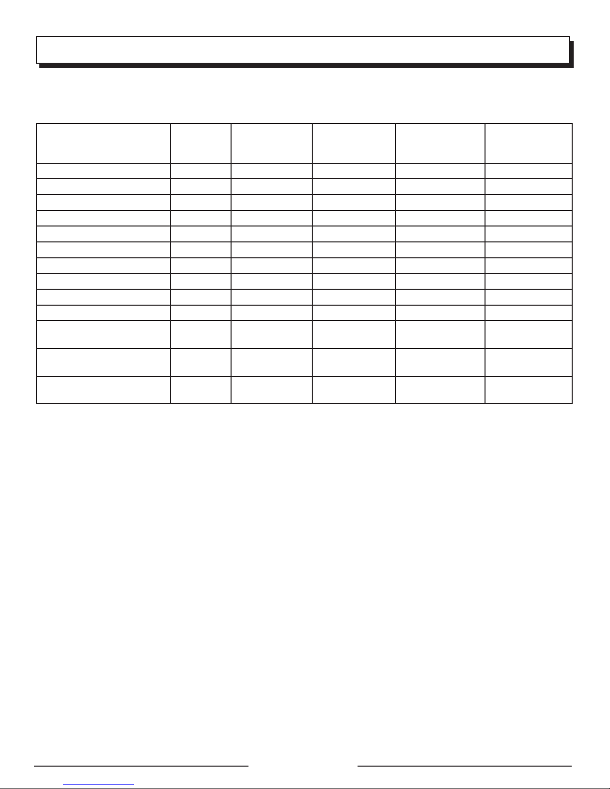
MAINTENANCE SCHEDULE
NOTE: If a separate engine manual is provided for this generator, please follow the maintenance schedule provided in the
engine manual instead of the maintenance information listed below.
Before
each use
Check Engine Lubricant
Change Engine Lubricant
Check Air Filter
Clean Air Filter
Change Air Filter
Check/Adjust Spark Plug
Replace Spark Plug
Check/Clean Spark Screen
Clean Fuel Tank and Filter
Check Fuel Hose
Check All Hose
Connections
Inspect Fuel Tank Vapor
Vent (If Equipped)
Inspect Carbon Canister
(CARB Models Only)
1. These items should only be carried out by a qualified service center.
NOTE: Maintenance should be performed more frequently when generator is used in dusty areas.
When generator has exceeded the maximum figures specified in the table, maintenance should still be cycled
according to the intervals of time or hours stated herein.
1
After 1st month
or 20 hours of
operation
Every 3 months
or 50 hours of
operation
Every 6 months
or 100 hours
of operation
Every year or
after 300 hours
of operation
Page 18 — English
Page 23
TROUBLESHOOTING
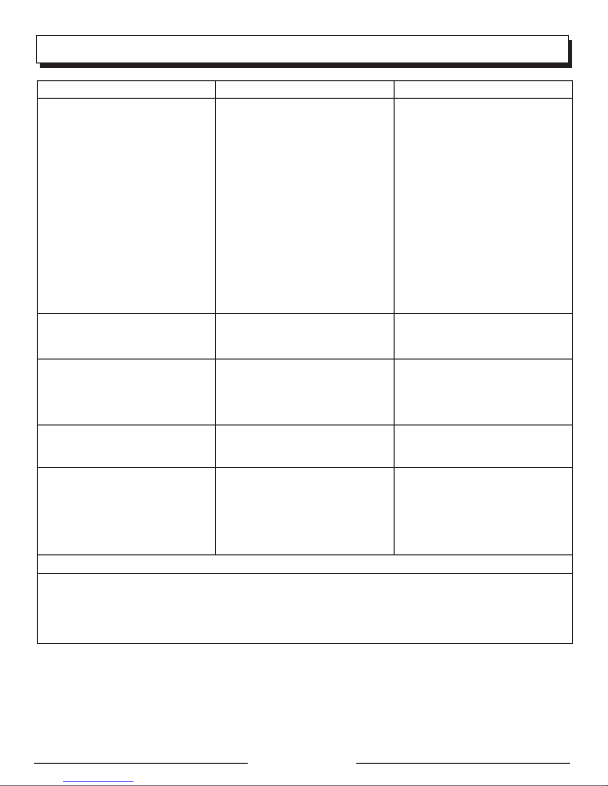
PROBLEM POSSIBLE CAUSE SOLUTION
Engine will not start. On/Off switch is OFF (O).
No fuel.
Stale gasoline or water in gasoline.
Lubricant level is low.
Spark plug faulty, fouled, or improperly
gapped.
Choke lever is in RUN position.
Engine stored without treating or
draining gasoline, or refueled with bad
gasoline.
Dirty fuel filter.
Engine hard to start. Water in gasoline.
Weak spark at spark plug.
Engine lacks power. Dirty air filter.
Engine stored without treating or
draining gasoline, or refueled with bad
gasoline.
AC receptacle does not work. Generator is overloaded.
Item plugged in is defective.
Generator makes a “spark knock” or
“pinging” noise.
If problem persists after trying the above solutions, contact customer service or a qualified service center for assistance.
An occasional light “knocking” or “pinging” under heavy load is not a cause
for concern. However, if the knocking
or pinging occurs under normal load
at a steady engine speed, the problem
may be with the brand of gasoline being used.
Turn On/Off switch to ON (I).
Fill fuel tank.
Drain entire system and refill with fresh
fuel.
Engine is equipped with Low Oil Shutoff.
If engine lubricant level is low, it must be
filled before unit will start. Check engine
lubricant level and fill, if necessary.
Replace spark plug.
Put the choke lever in the START
position.
Drain fuel and carburetor. Refuel with
fresh gasoline.
Contact a qualified service center.
Drain entire system and refill with fresh
fuel.
Contact a qualified service center.
Check air filter. Clean or replace as
needed.
Drain fuel and carburetor. Refuel with
fresh gasoline.
Remove loads and press the reset
button.
Try a different item.
Switch to a different brand of gasoline,
making sure that the octane rating is 86
or higher. If problem continues, contact
a qualified service center.
NOTICE:
As the equipment owner, you are responsible for the performance of the required maintenance listed in the Maintenance
section It is recommended that you retain all receipts covering maintenance on your equipment. Neglecting or failing
to perform the required maintenance may increase emissions, decrease fuel efficiency, degrade performance, cause
irreversible engine damage and/or void your warranty.
Page 19 — English
Page 24
WARRANTY
LIMITED WARRANTY
WARRANTY COVERAGE
OWT Industries, Inc., (the Company) warrants to the original retail purchaser that this Black Max Product is free from
defects in material and workmanship and agrees to repair or replace, at the Company’s sole discretion, any defective
Product free of charge within these time periods from the date of purchase:
Two years, if the Product is used solely for personal, family, or household use;
90 days, if the Product is used for business or commercial use.
This warranty applies only to Products sold within the United States of America, the District of Columbia, Canada,
Mexico, the Commonwealth of Puerto Rico, the Virgin Islands, Guam, the Canal Zone, or American Samoa.
This warranty is not transferable and does not cover damage resulting from defects other than in material or workmanship, or damage caused by unreasonable use, including the failure to provide reasonable and necessary maintenance.
Other items not covered under this warranty include:
Transportation charges for sending the product to the Company or its authorized service representative for warranty
service, or for shipping repaired or replacement products back to the customer; these charges must be borne by
the original retail purchaser.
Engine. Your Product is equipped with an engine that is covered exclusively by a separate warranty from the engine
manufacturer. Please refer to the engine manual included with the Product for warranty information related to the
engine.
Damages caused by abuse, accident, misuse, neglect, alteration, modification, the effects of corrosion, erosion,
normal wear and tear or repairs by other than the Company or its authorized service representative.
Warranty is voided if the customer fails to install, maintain and operate the product in accordance with the instructions and recommendations of the Company as set forth in the Product’s operator’s manual or if the Product is used
as rental equipment.
The Company will not pay for repairs or adjustments to the Product, or for any costs or labor, performed without the
Company’s prior authorization.
IMPORTANT: Some components not covered under this warranty may still be covered by a separate warranty
issued by the engine manufacturer. Please see the Engine Manufacturer Warranty (if any) supplied with this
product for further details.
Proof of purchase in the form of your dated sales receipt, cash register slip, etc. showing the serial number and the
model of your Product will be required before the Company and/or its authorized service representatives can perform
warranty service on the Product.
THIS LIMITED WARRANTY IS IN LIEU OF ALL OTHER EXPRESS WARRANTIES. ANY IMPLIED WARRANTY OF
MERCHANTABILITY, FITNESS FOR A PARTICULAR PURPOSE, OR OTHERWISE, APPLICABLE TO THIS PRODUCT,
SHALL BE LIMITED IN DURATION TO THE DURATION OF THIS LIMITED WARRANTY. THE WARRANTY SERVICE
DESCRIBED ABOVE IS THE EXCLUSIVE REMEDY UNDER THIS WARRANTY. THE COMPANY SHALL NOT BE LIABILE
FOR ANY SPECIAL, INCIDENTAL OR CONSEQUENTIAL DAMAGES.
SOME STATES DO NOT ALLOW A LIMITATION ON THE DURATION OF IMPLIED WARRANTIES, OR THE EXCLUSION
OR LIMITATION OF INCIDENTAL, OR CONSEQUENTIAL DAMAGES, SO THE ABOVE LIMITATION OR EXCLUSION
MAY NOT APPLY TO YOU.
HOW TO OBTAIN WARRANTY SERVICE
For warranty service: Call toll free 1-800-726-5760, or write to OWT Industries, Inc., P.O. Box 35, Highway 8,
Pickens, SC 29671.
For warranty service outside the USA, please contact your local Black Max dealer.
SAVE YOUR SALES SLIP
EXCLUSIONS AND LIMITATIONS
Page 20 — English
Page 25

WARRANTY
LIMITED ENGINE WARRANTY
OWT Industries, Inc., (the Company), warrants that each new engine sold by it will be free, under normal use and
service, from defects in material and workmanship for a period listed below from the date of sale to the original retail
purchaser. The Company’s obligation under this Limited Warranty shall be limited to the repair and replacement, at
the Company’s option, of any part or parts which upon examination is/are found, in the Company’s judgment, to have
been defective in material or workmanship. It shall be a condition of the Company’s obligation under this Limited
Warranty that the Company, directly or through one of its Distributors or Service Centers authorized to service the
particular engine involved, receive prompt notice of any warranty claim and that the engine or the part or parts claimed
to be defective be promptly delivered, transportation prepaid, to such Distributor or Service Center for inspection and
repair. All repairs qualifying under this Limited Warranty must be performed by the Company or one of its authorized
Distributors or Service Centers.
WARRANTY PERIODS:
144F Gasoline Engine (Private/Residential) Limited 2 year Warranty
144F Gasoline Engines (Commercial) Limited 90 Day Warranty
The repair or replacement of any part or parts under this Limited Warranty shall not extend the term of the engine
warranty beyond the original term as set forth above.
LIMITATIONS AND EXCLUSIONS: This Limited Warranty shall not apply to:
1. Repair required because of prolonged storage including damage caused by old or contaminated fuel in the fuel tank,
fuel lines, or carburetor, sticky valves or corrosion and rust of engine parts.
2. Repair required due to overheating. (Most often caused by overloaded or clogged or damaged or missing flywheel,
fan, inlet air passages, cooling fins, or air shrouds.)
3. Dirt or grit related wear caused by improper air cleaner maintenance (most often resulting in worn piston, piston
rings, cylinders, valves, valve guides, carburetor, or other internal components).
4. Broken or scored parts caused by low oil level, dirty, or improper grade of oil.
5. Engine tune-ups and normal maintenance service including, but not limited to, valve adjustment, normal replacement
of service items, fuel, and lubricating oil, etc.
6. Any engine which has been subject to negligence, misuse, accident, misapplication, or overspeeding.
7. Any engine that has been installed, repaired, or altered by anyone in a manner which in the Company’s sole judgment
adversely affects its performance or reliability.
8. Any engine which has been fitted with or repaired with parts or components not manufactured or approved by OWT
Industries, Inc. which in the Company’s sole judgment adversely affects its performance or reliability.
9. Instances when normal use has exhausted the life of a component or an engine.
The customer is responsible for all transportation charges in connection with any warranty work.
The Company reserves the right to modify, alter, or improve any engines or parts without incurring any obligation to
modify or replace any engine or parts previously sold without such modification, alternation, or improvement.
No person is authorized to give any other warranty or to assume any additional obligation on the Companys’ behalf
unless made in writing and signed by an officer of the Company.
THIS WARRANTY, OWT INDUSTRIES, INC. OBLIGATION HERE UNDER, ARE IN LIEU OF ANY OTHER WARRANTIES
OR OBLIGATIONS OF ANY KIND, EXPRESSED OR IMPLIED, INCLUDING ANY WARRANTIES OF MERCHANTABILITY
OR FITNESS FOR A PARTICULAR PURPOSE. THERE ARE NO WARRANTIES WHICH EXTEND BEYOND THE
DESCRIPTION ON THE FACE HERE-OF. OWT INDUSTRIES, INC. SHALL IN NO EVENT BE LIABLE FOR ANY
CONSEQUENTIAL OR INCIDENTAL DAMAGES.
IF YOU HAVE ANY QUESTIONS REGARDING YOUR WARRANTY RIGHTS
AND RESPONSIBILITIES, CONTACT OWT INDUSTRIES, INC. AT 1-800-726-5760.
Page 21 — English
Page 26

NOTES
Page 22 — English
Page 27
Para registrar su producto de Black Max,
por favor visita: www.blackmaxtools.com
UBIQUE EL GENERADOR A UNA DISTANCIA DE POR LO MENOS 6 M (20 PIES)*
PARA REDUCIR EL RIESGO DE QUE EL MONÓXIDO DE CARBONO
INGRESE EN LA CASA
* Distancia mínima recomendada por el Departamento de Salud y Servicios Humanos y por los
Centros para el Control y la Prevención de Enfermedades de los Estados Unidos (www.cdc.gov/co).
Las condiciones particulares de su casa o del viento puede requerir una distancia adicional.
MANTEGA UNA DISTANCIA DE
Escape (CO)
Dirija el escape LEJOS
de ventanas, puertas y
orificios de ventilación.
ADVERTENCIA:
CONEXIÓN A TIERRA DEL GENERADOR
Si este generador se utiliza únicamente con aparatos conectados con
cable y enchufe, el Código Eléctrico Nacional no exige que la unidad esté
puesta a tierra. Sin embargo, si se usa el generador de otra forma, podría
ser necesario ponerlo a tierra para reducir el riesgo de descargas eléctricas
o electrocución. Antes de usar el generador, consulte a un electricista
calificado, un inspector eléctrico o un organismo local que tenga jurisdicción
para saber si es necesario ponerlo a tierra en su situación.
Si es necesario poner a tierra la unidad, deben utilizarse la tuerca y el
terminal de conexión a tierra del bastidor para conectar el generador a una
fuente apropiada de conexión a tierra. La conexión a tierra debe realizarse
con alambre calibre Nº 8. Conecte el terminal del alambre de conexión a
tierra entre la arandela y la tuerca, y apriete firmemente la tuerca. Conecte
el otro extremo del alambre firmemente a una fuente apropiada de conexión
a tierra que esté en contacto con el suelo a lo largo de una distancia de al
menos 2,4 m (8 pies).
El Código Eléctrico Nacional especifica varias maneras prácticas para
establecer una buena fuente de conexión a tierra. Si se utiliza una barra de
acero o de hierro, éste debe ser de 15,9 mm (5/8 pulg.) de diámetro, y si
se utiliza una barra no ferrosa, ésta debe ser de 13 mm (1/2 pulg.) de diámetro como mínimo y estar listada como material
adecuado para conexión a tierra. Si encuentra un estrato rocoso antes de llegar a una profundidad de 2,4 m (8 pies), clave
la jabalina de puesta a tierra a un ángulo de a lo sumo 45°. Si aun así la jabalina se encuentra con el estrato rocoso, se la
puede enterrar en una trinchera de al menos 75 cm (30 pulg.) de profundidad. En cualquier caso, el extremo superior de la
jabalina debe estar al ras del suelo (o por debajo del rasante) o protegido de posibles daños físicos por otro medio.
Todas las herramientas eléctricas y aparatos alimentados por este generador deben conectarse apropiadamente a tierra
mediante el uso de un tercer alambre o tener un diseño con “doble aislamiento”.
Se recomienda:
1. Usar dispositivos eléctricos con clavija de tres patillas conectada a tierra.
2. Para asegurar la continuidad de la protección a tierra del generador al dispositivo, utilice un cordón de extensión para
uso a la intemperie con un receptáculo de tres orificios en un extremo y una clavija de tres patillas en el otro.
Revise y cumpla con todas las reglas federales, estatales y locales relevantes en relación con las especificaciones de conexión
a tierra. Consulte a un electricista calificado o técnico de servicio si no ha comprendido completamente las instrucciones
de conexión a tierra o si no está seguro si el generador está conectado a tierra correctamente.
POR LO MENOS 6 M (20 PIES)
Utilícelo únicamente EN EL EXTERIOR
y ALEJADO de ventanas, puertas y
orificios de ventilación.
Detector de CO
en áreas habitadas
Página 2 — Español
Page 28
INSTRUCCIONES DE SEGURIDAD IMPORTANTES
PELIGRO:
Monóxido de carbono. Usar un generador en el interior LO
MATARÁ EN POCOS MINUTOS.
Los gases de escape del generador contienen niveles altos
de monóxido de carbono (CO), un gas venenoso que no
puede verse ni olerse. Si puede oler los gases de escape
del generador, está respirando CO. Pero incluso si no puede
oler los gases de escape, es posible que esté respirando CO.
Nunca use un generador dentro de su hogar, garaje,
sótano, ni demás espacios parcialmente encerrados. En
dichos espacios, pueden acumularse niveles mortales
de monóxido de carbono. Usar un ventilador o abrir
puertas y ventanas NO proporciona suficiente aire
fresco.
SÓLO utilice el generador al aire libre y lejos deventanas,
puertas y respiraderos abiertos. Estas aberturas pueden
atraer los gases de escape del generador.
Incluso si utiliza el generador correctamente, el CO puede
ingresar en su hogar. SIEMPRE utilice una alarma de CO de
pilas o con pilas de respaldo en su hogar.
Si comienza a sentirse descompuesto, mareado o débil
luego de que el generador estuvo funcionando, trasládese
adonde haya aire fresco INMEDIATAMENTE. Vea a un doctor.
Puede sufrir intoxicación por monóxido de carbono.
ADVERTENCIA:
Lea y comprenda todas las instrucciones. El
incumplimiento de cualquiera de las instrucciones siguientes
puede causar electrocución, incendio o intoxicación por
monóxido de carbono, lo cual puede causar la muerte o
lesiones graves.
ADVERTENCIA:
En ciertas aplicaciones, el Reglamento Nacional de
Electricidad exige que el generador esté conectado
a una tierra aprobada. Antes de utilizar la terminal de
tierra, consulte a un electricista calificado, inspector de
instalaciones eléctricas u organismo gubernamental de
la localidad en lo referente a las reglas y disposiciones
relacionadas con el uso deseado del generador.
GUARDE ESTAS INSTRUCCIONES
Este manual contiene importantes instrucciones que se deben
seguir durante la instalación y las actividades de mantenimiento
del generador y las baterías.
No conecte la unidad al sistema eléctrico de un edificio a
menos que el generador y el interruptor de transferencia se
hayan instalado correctamente y que un electricista calificado
haya verificado la salida de energía eléctrica. La conexión
debe aislar la corriente del generador del servicio público
y debe cumplir con todas las leyes y los códigos eléctricos
pertinentes.
No permita que utilicen esta unidad niños ni personas
carentes de la debida instrucción para su manejo.
No haga arrancar o funcionar el motor en un espacio
confinado, de edificio, cerca de ventana abiertas, o en
otro área sin ventilación donde se puedan recolectar las
emanaciones de monóxido de carbono. El monóxido de
carbono, un gas incoloro, inodoro y sumamente peligroso,
puede causar la pérdida de la conciencia o la muerte.
Mantenga a todos los circunstantes, niños y animales por
lo menos a 3 m (10 pies) de distancia.
Use botas o zapatos robustos y secos. No utilice la unidad
estando descalzo.
No utilice este generador cuando se encuentre fatigado,
enfermo o bajo los efectos de drogas, alcohol o
medicamentos.
Mantenga todas las partes del cuerpo alejadas de toda pieza
móvil y superficie caliente de la unidad.
No toque cables ni receptáculos desprovistos de aislamiento.
No utilice el generador con cordones de corriente gastados,
deshilachados, pelados o dañados de cualquier forma.
Antes de guardar la unidad, deje que se enfríe el motor
durante 30 minutos y retire el combustible de la unidad.
No utilice or guarde el generador en la lluvia, nieve o tiempo
húmedo.
Guarde el generador en un lugar bien ventilado y con el
tanque de combustible vacío. El combustible no se debe
guardar cerca del generador.
Antes de transportar la unidad en un vehículo, gire el
interruptor de encendido y apagado/ válvula de combustible
a apagado, vacíe el tanque de combustible e inmovilice
aquélla.
Coloque una lámina de plástico o una almohadilla absorbente
debajo del generador para atrapar las gotas de combustible
o lubricante cuando lo transporte.
Para reducir el riesgo de incendio o de lesiones por
quemadura, maneje con cuidado el combustible. Es
sumamente inflamable.
No fume mientras esté mezclando el combustible o
reabasteciendo el tanque.
Almacene el combustible en un recipiente aprobado para
gasolina.
Coloque la unidad sobre el piso nivelado, apague el motor,
y deje que se enfríe durante cinco minutos antes de
reabastecerlo de combustible.
Afloje la tapa del tanque de combustible para aliviar la presión
y para evitar que se escape combustible por la tapa.
Después de reabastecer de combustible la unidad ponga
la tapa y apriétela firmemente.
Limpie todo el combustible que se haya derramado de la
unidad.
Nunca intente en ninguna circunstancia eliminar el
combustible derramado quemándolo.
Los generadores vibran durante el uso normal. Durante y
después del uso del generador, inspeccione el generador,
así como los cordones de extensión y los cordones de
corriente conectados a éste, para ver si tienen daños
causados por la vibración. Deben repararse o reemplazarse
los artículos dañados, según sea necesario. No use enchufes
Página 3 — Español
Page 29
INSTRUCCIONES DE SEGURIDAD IMPORTANTES
ni cordones que muestren señales de daño, como roturas
o agrietamientos en el aislamiento, o daño en las espigas.
Los generadores fijos instalados de manera permanente
son la mejor alternativa para abastecer de electricidad al
hogar durante los cortes de energía. Incluso los generadores
portátiles que están conectados correctamente pueden
sobrecargarse. De esta manera, los componentes del
generador pueden recalentarse o exigirse demasiado, lo
que podría producir una falla en el generador.
Solo utilice piezas de repuesto recomendadas o equivalents
y accessorios y siga las instrucciones descritas en la
REGLAS DE SEGURIDAD ESPECÍFICAS
PELIGRO:
Riesgo de incendios y lesiones por quemaduras: Nunca
retire la tapa de combustible mientras esté encendida la
unidad. Apague el motor y deje enfriar la unidad durante al
menos cinco minutos. Retire la tapa lentamente.
ADVERTENCIA:
Cuando este generador se utiliza para abastecer el
sistema de cableado de un edificio: un electricista
calificado debe instalar el generador, que debe conectarse
a un interruptor de transferencia como un sistema derivado
independiente, de conformidad con el Reglamento Nacional
de Electricidad (NFPA 70). El generador se conectará a
través de un interruptor de transferencia que controla todos
los conductores, excepto el conductor de conexión a tierra
del equipo. El bastidor del generador debe conectarse a
un electrodo de conexión a tierra aprobado. Si no se aísla
el generador de las líneas de alto voltaje puede causarse la
muerte o lesiones a los trabajadores de dichas líneas.
No utilice este generador para suministrar energía a
dispositivos de soporte vital o equipos médicos de
emergencia.
Este generador tiene un punto neutro flotante. Esto significa
que el conductor neutro no está conectado por vías eléctricas
al marco de la máquina.
Siempre use un detector de monóxido de carbono de
baterías al utilizar el generador. Si comienza a sentirse mal,
mareado o débil al estar utilizando el generador, apáguelo
y respire aire fresco de inmediato. Vea a un doctor. Puede
sufrir intoxicación por monóxido de carbono.
Coloque el generador en una superficie estable horizontal
con una pendiente de no más de 4°.
Utilice la unidad al aire libre en un área bien ventilada e
iluminada, aislada de las áreas de trabajo para evitar la
interferencia del ruido.
Si se utiliza el generador en condiciones húmedas, puede
causarse una electrocución. Mantenga seca la unidad.
sección de Mantenimiento de este manual. El empleo de
piezas diferentes o el incumplimiento de las instrucciones
de mantenimiento puede significar un riesgo de descarga
eléctrica o de lesiones.
Mantenga la unidad según las instrucciones de mantenimiento
señaladas en este manual del operador.
Inspeccione cada vez la unidad antes de usarla para ver si
tiene tornillos flojos, fugas de combustible, etc. Reemplace
toda pieza dañada.
Mantenga el generador a una distancia mínima de 914 mm
(3 pies) de todo tipo de material combustible.
No utilice el generador cerca de materiales peligrosos.
No utilice el generador en una estación de abastecimiento
de gasolina o gas natural.
No toque el silenciador ni el cilindro durante el funcionamiento
de la unidad ni inmediatamente después; están CALIENTES
y causan lesiones por quemadura.
No permita que se derrame el tanque del generador al
abastecerlo de gasolina. Llénelo hasta una altura de 25,4
mm (1 pulg.) abajo del cuello del tanque de gasolina para
permitir la expansión del combustible. Revise el orificio de
ventilación del interior del tanque de combustible para ver
si tiene basura. No bloquee el respiradero.
No fume mientras abastece de gasolina el generador.
Apague el motor y déjelo enfriar durante cinco minutos antes
de agregar gasolina o lubricante al generador.
No retire la varilla de nivel de aceite ni la tapa del tanque del
combustible mientras esté funcionando el motor.
Preste atención en particular a todas las etiquetas de
seguridad adheridas al generador.
En todo momento mantenga a los niños a una distancia
mínima de 3 m (10 pies) del generador.
La unidad funciona mejor a una temperatura entre -5 y 40
°C (23 y 104 °F) con una humedad relativa de 90% o menos.
El requerimiento de voltaje y frecuencia operativa de todos los
equipos electrónicos debe comprobarse antes de enchufarlos
a este generador. Pueden ocurrir daños si el equipo no está
diseñado para operar dentro de una variación de voltaje
de +/-10% y una variación de frecuencia de +/-3 hz de los
valores nominales que aparecen en la placa de identificación
del generador.
Para usarse sólo en el exterior
Guarde estas instrucciones. Consúltelas con frecuencia y
empléelas para instruir a otras personas que puedan utilizar
esta producto. Si presta a alguien esta producto, facilítele
también las instrucciones.
Página 4 — Español
Page 30
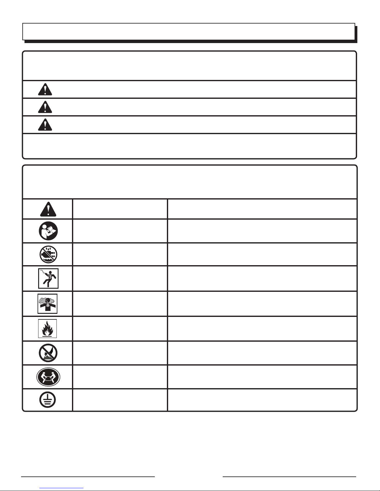
SÍMBOLOS
Las siguientes palabras de señalización y sus significados tienen el objeto de explicar los niveles de riesgo relacionados con este
producto.
SÍMBOLO SEÑAL SIGNIFICADO
PELIGRO:
Indica una situación peligrosa inminente, la cual, si no se evita, causará la muerte
o lesiones serias.
ADVERTENCIA:
PRECAUCIÓN:
AVISO:
Es posible que se empleen en este producto algunos de los siguientes símbolos. Le suplicamos estudiarlos y aprender su significado.
Una correcta interpretación de estos símbolos le permitirá utilizar mejor y de manera más segura el producto.
Indica una situación peligrosa posible, la cual, si no se evita, podría causar la
muerte o lesiones serias.
Indica una situación peligrosa posible, la cual, si no se evita, podría causar lesiones
menores o leves.
(Sin el símbolo de alerta de seguridad) Indica información importante no
relacionada con ningún peligro de lesiones, como una situación que puede
ocasionar daños físicos.
SÍMBOLO NOMBRE DESIGNACIÓN/EXPLICACIÓN
Alerta de seguridad Indica un peligro posible de lesiones personales.
Lea el manual del operador
Alerta de condiciones húmedas No exponga la unidad a la lluvia ni la use en lugares húmedos.
Descarga eléctrica
Emanaciones tóxicas
Fuego / Explosión
Superficie caliente y gases de
escape
Para reducir el riesgo de lesiones, el usuario debe leer y comprender el
manual del operador antes de usar este producto.
Si no se usa la unidad en condiciones secas y no se observan prácticas
seguras de trabajo, puede producirse una descarga eléctrica.
Con el funcionamiento del generador se emite monóxido de carbono, un
gas tóxico incoloro e inodoro. Si se inhala monóxido de carbono puede
causarse náusea, desmayo o la muerte.
El combustible y los vapores del mismo son extremadamente inflamables
y explosivos. El fuego o una explosión pueden causar quemaduras graves
e incluso la muerte.
Para reducir el riesgo de lesiones corporales o daños materiales evite tocar
toda superficie caliente y no coloque partes del cuerpo en la trayectoria
de los gases de escape.
Peligro al levantar
Conexión a tierra
Para reducir el riesgo de lesiones serias, evite intentar levantar el generador
usted solo.
Consulte a un electricista de la localidad para determinar los requisitos
de conexión a tierra antes de utilizar la unidad.
Página 5 — Español
Page 31
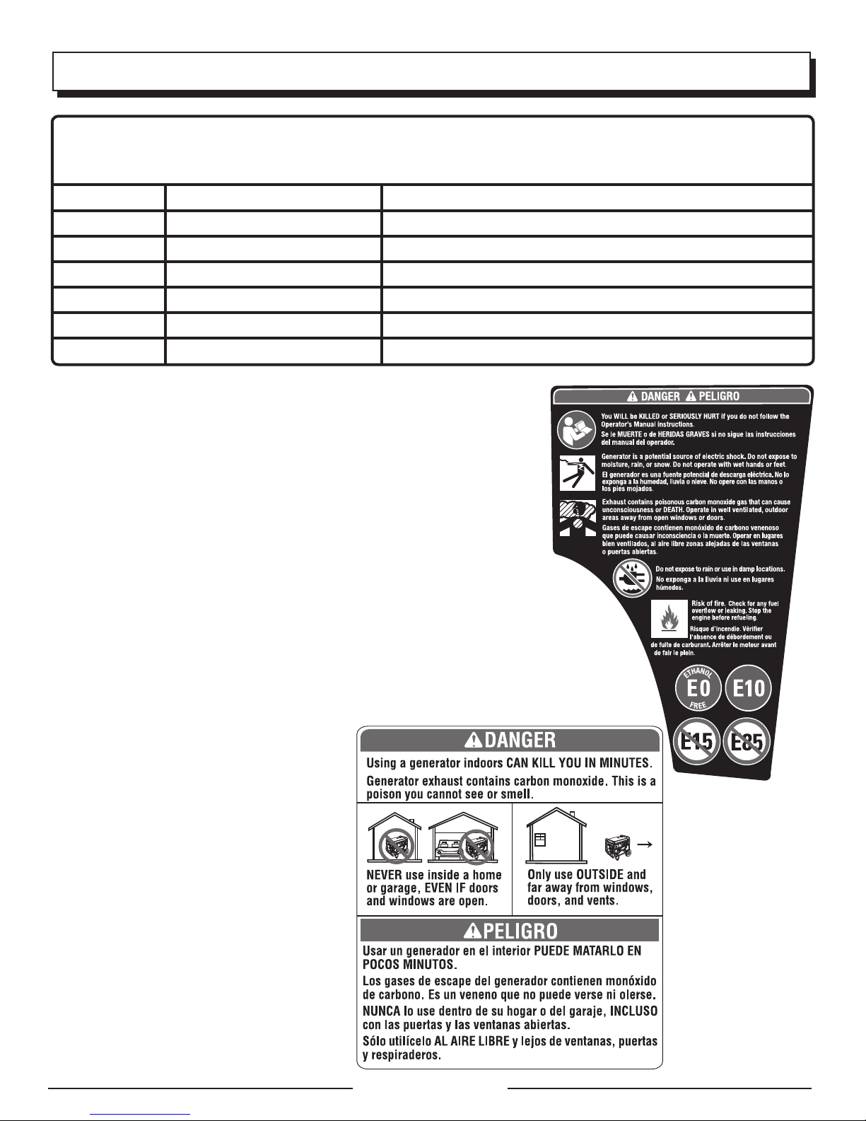
SÍMBOLOS
Es posible que se empleen en este producto algunos de los siguientes símbolos. Le suplicamos estudiarlos y aprender su significado.
Una correcta interpretación de estos símbolos le permitirá utilizar mejor y de manera más segura el producto.
SÍMBOLO NOMBRE DENOMINACIÓN / EXPLICACIÓN
V Voltios Voltaje
A Amperios Corriente
Hz Hertz Frecuencia (ciclos por segundo)
W Watt Potencia
hrs Horas Tiempo
gal Galón Volumen
qt Cuarto Volumen
ETIQUETAS DE SEGURIDAD
La siguiente información puede encontrarse en el generador. Para su propia
seguridad, le sugerimos estudiar y entender todas la etiquetas antes de poner
marcha el generador.
Si se desprende de la unidad cualquiera de las etiquetas o se vuelven ilegibles,
comuníquese con algún el servicio al cliente o con un centro de servicio
calificado para obtener un reemplazo.
SE MATARÁ o LESIONARÁ GRAVEMENTE si no sigue las instrucciones del
Manual del operador.
Riesgo de incendio. No agregue combustible cuando el producto esté
functionando.
El generador es una fuente potencial de descarga eléctrica. No lo exponga
a humedad, la lluvia nin a la nieve. No opere con manos o pies húmedos.
El escape contiene gas venenoso de monóxido de carbono que puede
causar pérdida del conocimiento a la MUERTE. Opere en áreas exteriores
bien ventiladas lejos de puertas o ventanas abiertas.
No exponga la unidad a la lluvia ni la use en lugares húmedos.
Usar un generador en el interior PUEDE
MARTARLO EN POCOS MINUTOS. Los
gases de escape del generador contienen
monóxido de carbono. Es un veneno que
no puede verse ni olerse.
NUNCA lo use dentro de su hogar o del
garaje, INCLUSO con las puertas y las
ventanas abiertas.
Sólo utilícelo AL AIRE LIBRE y lejos de
ventanas, puertas y respiraderos.
ADVERTENCIA DE COMBUSTIBLE
No fume al abastecer el combustible. No llene
de más. El nivel de lleno es 25,4 mm (1 pulg.)
debajo del cuello del tanque de combustible.
Pare la marcha del motor cinco minutos antes
del reabastecimiento de combustible para
evitar que el calor del silenciador encienda los
vapores de combustible.
Página 6 — Español
Page 32

SÍMBOLOS
ADVERTENCIA PARA LA TANQUE DE COMBUSTIBLE
Nunca retire la tapa de combustible mientras esté encendida
la unidad. Apague el motor y deje enfriar la unidad durante al
menos cinco minutos. Quite la tapa lentamente para liberar la
presión que se haya acumulado en el sistema de combustible
y para evitar que el calor del silenciador provoque la ignición
de los vapores del combustible.
ADVERTENCIA DEL LUBRICANTE DE MOTOR
Antes de utilizar el generador debe abastecerlo de lubricante.
Antes de utilizar la unidad, revise el nivel de lubricante. El
nivel de lubricante siempre debe estar entre las áreas cubierta
con rayas entrecruzadas de la varilla de nivel. La unidad está
equipada de un sensor, el cual apaga automáticamente el
motor si el nivel de lubricante desciende abajo del límite de
seguridad.
ADVERTENCIA ACERCA DE LA CONEXIÓN A TIERRA
Este generador no incluye un cable de cobre ni
una jabalina de puesta a tierra. Consulte con un
electricista calificado para conocer los requisitos
locales de puesta a tierra.
WARNING
ADVERTENCIA
ADVERTENCIA DE SUPERFICIE CALIENTE
No toque el silenciador ni el cilindro de aluminio del motor.
Están muy CALIENTES y causan quemaduras graves.
No ponga ningún partes del cuerpo o material inflamable
o combustible directamente en la trayectoria de las
emanaciones del escape.
ADVERTENCIA DE ESPACIO
LIBRE
Tanto en funcionamiento como
al guardarlo, mantenga siempre
91,4 cm (3 pies) de espacio
libre en todos los laterales de
Risk of Fire. Keep all objects at least 3 feet away from this machine. Heat from Muffler and Exhaust gases
can ignite combustible objects.
Riesgo de incendio. Mantener todos los objetos a una distancia mínima de 91,4 cm (3 pies) de esta
máquina. El calor de los gases del silenciador y el escape pueden prender fuego a objetos combustibles.
940974090-03
este producto, incluida la parte
superior. Aguarde al menos 30
minutos para el equipo se enfríe antes de guardarlo. El calor
generado por el silenciador y los gases de escape puede
ser suficiente para causar quemaduras graves y/o prender
fuego a objetos combustibles.
PARACHISPAS
El uso de este equipo puede producir chispas
propensas a iniciar incendios cerca de vegetación
seca. Es posible que se necesite un parachispas.
El operador debe ponerse en contacto con las
agencias contra incendios locales para conocer
las leyes y regulaciones relacionadas con los
requisitos de prevención de incendios.
DANGER PELIGRO
Página 7 — Español
Page 33
ASPECTOS ELÉCTRICOS
CALIBRE DEL CORDÓN DE EXTENSIÓN
Consulte el cuadro mostrado abajo para asegurarse de que el calibre de los cordones de extensión que utilice puedan
con la carga eléctrica requerida. Los cordones de calibre insuficiente pueden causar una caída de voltaje, lo cual puede
quemar el dispositivo y recalentar el cordón mismo.
Corriente en
Amperios
2,5 300 600 305 m (1000 pies) 183 m (600 pies) 114 m (375 pies) 76 m (250 pies)
5 600 1200 152 m (500 pies) 91 m (300 pies) 61 m (200 pies) 38 m (125 pies)
7,5 900 1800 107 m (350 pies) 61 m (200 pies) 38 m (125 pies) 31 m (100 pies)
10 1200 2400 76 m (250 pies) 46 m (150 pies) 31 m (100 pies) 15 m (50 pies)
15 1800 3600 46 m (150 pies) 31 m (100 pies) 20 m (65 pies)
20 2400 4800 53 m (175 pies) 38 m (125 pies) 23 m (75 pies)
25 3000 6000 46 m (150 pies) 31 m (100 pies)
30 3600 7200 38 m (125 pies) 20 m (65 pies)
40 4800 9600 27 m (90 pies)
Carga en vatios Longitud máxima permitida del cordón
A 120 V A 240 V Conduct. #8 Conduct. #10 Conduct. #12 Conduct. #14 Conduct. #16
CARGAS DE MOTORES ELÉCTRICOS
Es característico en el funcionamiento normal de los motores eléctricos comunes consumir durante el arranque hasta seis
veces su corriente de operación. Esta tabla puede emplearse para estimar la potencia necesaria (en vatios) para arrancar
los motores eléctricos; no obstante, si un motor eléctrico no arranca o no alcanza la velocidad de funcionamiento, apague
el dispositivo o herramienta de inmediato para evitar dañar el equipo. Siempre verifique los requisitos de la herramienta o
aparato con la salida nominal del generador.
Capacidad del motor
(H.P.)
1/8 275 N/A 850 1200
1/6 275 600 850 2050
1/4 400 800 1050 2400
1/3 450 950 1350 2700
1/2 600 1000 1800 3600
3/4 850 1200 2600 —
1 1100 N/A 3300 —
Potencia en marcha
(vatios)
Potencia necesaria para arrancar el motor (vatios)
Universal
Capacitor Fase dividida
AVISO:
El requerimiento de voltaje y frecuencia operativa de todos los equipos electrónicos debe comprobarse antes de
enchufarlos a este generador. Pueden ocurrir daños si el equipo no está diseñado para operar dentro de una variación
de voltaje de +/-10% y una variación de frecuencia de +/-3 hz de los valores nominales que aparecen en la placa
de identificación del generador. A fin de evitar daños, siempre tenga una carga adicional enchufada al generador en
caso de usarse equipos de estado sólido (tales como un aparato de televisión). También podría resultar necesario un
condicionador de la línea eléctrica para algunas aplicaciones; por ejemplo, con una computadora. También podria
resultar necesario un condicionador de la línea eléctrica para algunas aplicaciones de equipo de estado sólido.
Página 8 — Español
Page 34
ASPECTOS ELÉCTRICOS
CAPACIDAD DEL GENERADOR
Cerciórese que el generador pueda suministrar suficientes
vatios de potencia continua (en marcha) y de sobrecorriente
(al arrancar) para los equipos que desee alimentar al mismo
tiempo. Siga estos pasos sencillos.
1. Seleccione los equipos que desea alimentar al mismo
tiempo.
2. Sume la potencia continua (en marcha) en vatios de
estos equipos. Esta es la cantidad de potencia que el
generador debe producir para mantener en marcha los
equipos. Observe la tabla de referencia de potencia en
vatios, a la derecha.
3. Calcule cuánta potencia inicial (al arranque) en vatios
necesitará. La potencia inicial (en vatios) es la breve
variación rápida de potencia necesaria para poner en
marcha los aparatos o herramientas accionados con motor
eléctrico como las sierras circulares o los refrigeradores.
Debido a que no todos los motores arrancan al mismo
tiempo, se puede calcular la potencia inicial total en
vatios sumando sólo los equipos con el mayor valor de
potencia inicial adicional a la potencia nominal del paso 2.
Ejemplo:
Herramienta
o aparato
Refrigerador 700 1350
Ventilador portátil 40 120
Ordenador portátil 250 250
Televisión de pantalla plana de 116,8
cm (46 pulg.)
Luz (75 Watts) 75 75
Potencia continua total en vatios 1255
Potencia arranque máxima en vatios + 1350
Potencia total arranque en vatios requerida 2605
Potencia
continua
en vatios*
190 190
1255 vatios,
potencia en
marcha total
ADMINISTRACIÓN DE LA POTENCIA
A fin de prolongar la vida útil del generador y los dispositivos
acoplados, es importante tener cuidado al agregar cargas
eléctricas al generador. NO debe haber equipo alguno
conectado a los tomacorrientes del generador antes de poner
en marcha el motor respectivo. La manera correcta y segura
de administrar la potencia del generador consiste en agregar
las cargas de manera secuencial de la manera siguiente:
1. Sin equipos conectados al generador, ponga en marcha
el motor de la manera que se describe posteriormente
en este manual.
2. Enchufe y active la primera carga, preferiblemente la
máxima carga que tenga.
Potencia
arranque
en vatios*
1350 vatios,
potencia inicial
máxima
Página 9 — Español
3. Deje que se estabilice la salida del generador (el motor
marcha uniformemente y el dispositivo acoplado funciona
correctamente).
4. Enchufe y active la siguiente carga.
5. Nuevamente, deje que el generador se estabilice.
6. Repita los pasos 4 y 5 para cada carga adicional.
Nunca añada más cargas que las que permita la capacidad
del generador. Tenga especial cuidado al considerar las
cargas de sobrecorriente en la capacidad del generador
según se describió anteriormente.
AVISO:
No exceda la capacidad del generador. Si excede la
capacidad de corriente (amperios) y potencia (vatios) del
generador puede dañar el generador y los dispositivos
eléctricos conectados al mismo.
W de
Herramienta o aparato
Emergencia /
En casa espera
Luz (cant. 4 x 75 W) 300 300
Refrigerador 700 1350
Televisión de pantalla pla-
na de 116,8 cm (46 pulg.)
Receptor satelital 250 250
Ventilador portátil 40 120
Calentador 1300 1300
Ordenador portátil 250 250
Olla lenta 270 270
Radio 50 50
Sitio de trabajo
Taladro eléctrico − 3/8 HP 600 1000
Lámpara de trabajo de
halógeno de cuarzo
Sierra alternativa 960 1920
Sierra circular - 184 mm
(7-1/4 pulg.)
Sierra de ingletes − 254 mm
(10 pulg.)
Compresor de aire −
1/4 HP
Rociador de aire
comprimido − 1/3 HP
*Los valores de potencias en vatios indicados son aproximados.
Verifique la potencia real de cada herramienta o aparato.
Funcionamiento
Estimados*
190 190
1000 1000
1400 2300
1800 1800
970 1600
600 1200
W de
Arranque
Estimados*
Page 35

CARACTERÍSTICAS
ESPECIFICACIONES DEL PRODUCTO
MOTOR
Tipo de motor ................Leva única elevada (SOHC), 54 cc
Bujía de repuesto ...................Bosch A7RTC o equivalente
Volumen de aceite de motor .......................0,25 l (8,5 onz.)
Volumen de combustible .............................. 2,27 l (0,6 gal.)
GENERADOR
Voltaje nominal ........................................................... 120 V
Amperaje nominal........................................................ 7,5 A
Potencia en marcha .................................................. 900 W
Potencia de arranque ............................................. 1,000 W
Frecuencia nominal .................................................... 60 Hz
FAMILIARÍCESE CON EL GENERADOR
Vea la figura 1.
El uso seguro que este producto requiere la comprensión
de la información impresa en el producto y en el manual del
operador así como ciertos conocimientos sobre el proyecto
a realizar. Antes de usar este producto, familiarícese con
todas las características de funcionamiento y normas de
seguridad.
RECEPTÁCULOS DE 120 V, C.A.
El generador incorpora el siguiente tomas monofásicas
receptáculo de 60 Hz que son 120 V y 15A de corriente
alterna. El receptáculo pueden utilizarse para accionar los
aparatos, iluminación eléctrica, herramientas y motores
apropiados.
FILTRO DE AIRE
El filtro de aire ayuda a limitar la cantidad de tierra y polvo
que penetra a la unidad durante el funcionamiento.
INTERRUPTOR DE RALENTÍ AUTOMÁTICO
El interruptor de ralentí automático se utiliza para controlar la
velocidad del motor y conservar el combustible. Cuando el
interruptor está en la posición de ON (I) (encendido) y no hay
ningún artefacto conectado a la unidad, el motor se ralentiza.
Si se agrega un artefacto, la velocidad del motor aumentará
hasta alimentar la unidad. Si se extrae el artefacto, el motor
volverá a ralentí.
MANGO DE ACARREO
El generador tiene un mango de acarreo para facilitar el
transporte.
PALANCA DEL ANEGADOR
La palanca del anegador se emplea al arrancar el motor.
TANQUE DE COMBUSTIBLE
El tanque de combustible tiene una capacidad de 2,27 l
(0,6 gal.).
NOTA: El combustible circula desde el tanque de
combustible hasta el carburador sólo cuando el interruptor
de encendido y apagado/ válvula de combustible está en
la posición de ON (I) (encendido).
TERMINAL DE CONEXIÓN A TIERRA
El terminal de conexión a tierra se utiliza para ayudar a
conectar a tierra correctamente el generador como ayuda
de protección contra descargas eléctricas. Consulte con un
electricista local calificado con respecto a los requisitos de
conexión a tierra en el área geográfica donde se encuentre
usted.
VISOR DE DIODOS LUMINISCENTES
Los diodos luminiscentes indican si el generador está en
uso, está sobrecargado o si necesita lubricante.
PROTECCIÓN DE APAGADO POR BAJA
CANTIDAD DE ACEITE
El sensor de bajo nivel de aceite provoca la detención del
motor cuando el nivel de aceite en el cárter es insuficiente.
TAPA DE ACEITE/VARILLA PARA MEDIR EL
ACEITE
Retire la tapa de aceite/varilla para medir el aceite para
revisar el nivel y añadir lubricante al motor cuando sea
necesario.
INTERRUPTOR DE ENCENDIDO Y APAGADO/
VÁLVULA DE COMBUSTIBLE
El interruptor de encendido y apagado/ válvula de
combustible se utiliza en combinación con el mango del
arrancador y cuerda para arrancar del motor. Además se
utiliza para apagar del motor.
BOTÓN DE REAJUSTE
El botón de reajuste es utilizado para restablecer la
corriente si una sobrecarga ocurre. Para restablecer la
corriente, oprima el botón reset.
MANGO DEL ARRANCADOR Y CUERDA
El mango del arrancador y cuerda se usa (junto con el
interruptor de encendido y apagado/ válvula de combustible)
para arrancar el motor del generador.
TAPA DE COMBUSTIBLE VENTEADA
El generador tiene una tapa de combustible con una rejilla
que puede abrirse y cerrarse. Durante el funcionamiento
normal, la rejilla debe estar en la posición ABIERTA (I).
Página 10 — Español
Page 36
ARMADO
DESEMPAQUETADO
Embarcamos este producto completamente armado.
Extraiga cuidadosamente de la caja la herramienta y los
accesorios. Asegúrese de que estén presentes todos los
artículos enumerados en la lista de empaquetado.
ADVERTENCIA:
No use este producto si no está totalmente ensamblado o
si alguna pieza falta o está dañada. Si utiliza un producto
que no se encuentra ensamblado de forma correcta y
completa, puede sufrir lesiones graves.
Inspeccione cuidadosamente la unidad para asegurarse
que no haya sufrido ninguna rotura o daño durante el
transporte.
No deseche el material de empaquetado hasta que haya
inspeccionado cuidadosamente el producto y lo haya
utilizado satisfactoriamente.
Si hay piezas dañadas o faltantes, le suplicamos llamar
al 1-800-726-5760, donde le brindaremos asistencia.
FUNCIONAMIENTO
LISTA DE EMPAQUETADO
Generador
Lubricante de motor (SAE 10W 30)
Embudo
Llave para bujía
Manual del operador
ADVERTENCIA:
Si falta o está dañada alguna pieza, no utilice este
producto sin haber reemplazado la pieza. Usar este
producto con partes dañadas o faltantes puede causar
lesiones serias al operador.
ADVERTENCIA:
No intente modificar esta producto ni introducir
accesorios no recomendados para la misma. Cualquier
alteración o modificación constituye maltrato y puede
causar una condición peligrosa, y como consecuencia
posibles lesiones corporales graves.
PELIGRO:
Monóxido de carbono. Usar un generador en el interior
LO MATARÁ EN POCOS MINUTOS.
Los gases de escape del generador contienen niveles
altos de monóxido de carbono (CO), un gas venenoso
que no puede verse ni olerse. Si puede oler los gases de
escape del generador, está respirando CO. Pero incluso
si no puede oler los gases de escape, es posible que
esté respirando CO.
Nunca use un generador dentro de su hogar, garaje,
sótano, ni demás espacios parcialmente encerrados.
En dichos espacios, pueden acumularse niveles
mortales de monóxido de carbono. Usar un ventilador
o abrir puertas y ventanas NO proporciona suficiente
aire fresco.
SÓLO utilice el generador al aire libre y lejos de
ventanas, puertas y respiraderos abiertos. Estas
aberturas pueden atraer los gases de escape del
generador.
Incluso si utiliza el generador correctamente, el CO puede
ingresar en su hogar. SIEMPRE utilice una alarma de CO
de pilas o con pilas de respaldo en su hogar.
Si comienza a sentirse descompuesto, mareado o
débil luego de que el generador estuvo funcionando,
trasládese adonde haya aire fresco INMEDIATAMENTE.
Vea a un doctor. Puede sufrir intoxicación por monóxido
de carbono.
ADVERTENCIA:
Si este generador se utiliza únicamente con aparatos
conectados con cable y enchufe, el Código Eléctrico
Nacional no exige que la unidad esté puesta a tierra. Sin
embargo, si se usa el generador de otra forma, podría
ser necesario ponerlo a tierra para reducir el riesgo de
descargas eléctricas o electrocución. Antes de usar
el generador, consulte a un electricista calificado, un
inspector eléctrico o un organismo local que tenga
jurisdicción para saber si es necesario ponerlo a tierra
en su situación.
ADVERTENCIA:
No permita que su familiarización con este producto lo
vuelva descuidado. Tenga presente que un descuido de
un instante es suficiente para causar una lesión grave.
ADVERTENCIA:
No utilice ningún aditamento o accesorio no recomendado
por el fabricante de este producto. El empleo de
aditamentos o accesorios no recomendados podría
causar lesiones graves.
Página 11 — Español
Page 37

FUNCIONAMIENTO
AVISO:
El parachispas que acompaña a este producto no ha sido
evaluado por el Servicio Forestal del Departamento de
Agricultura de EE. UU. y no se puede usar en terrenos
forestales de EE. UU. Además, los usuarios del producto
deben cumplir con los reglamentos de prevención de
incendios locales, estatales y federales. Consulte a las
autoridades que correspondan. Póngase en contacto
con el servicio al cliente o un centro de servicio calificado
para comprar un parachispas de repuesto.
AVISO:
Antes de cada uso, inspeccione todo el producto para
detectar partes dañadas, faltantes o sueltas, como
tornillos, tuercas, pernos, tapas, etc. Apriete firmemente
todos los sujetadores y las tapas y no accione este
producto hasta que todas las partes faltantes o dañadas
sean reemplazadas. Póngase en contacto con el servicio
al cliente o con un centro de servicio calificado para
recibir asistencia.
APLICACIONES
Este generador está diseñado para suministrar alimentación
eléctrica para el funcionamiento de iluminación eléctrica
compatible, electrodomésticos, herramientas y cargas de
motor.
ANTES DE ACCIONAR LA UNIDAD
Sólo utilícelo AL AIRE LIBRE y guarde una distancia al
menos de 6 m (20 pies) alejado de ventanas, puertas
y orificios de ventilación según lo recomendado por el
Departamento de Salud y Servicios Humanos y por los
Centros para el Control y la Prevención de Enfermedades
de los Estados Unidos. Las condiciones particulares
de su casa o del viento puede requerir una distancia
adicional.
NUNCA lo use dentro de su hogar o del garaje, INCLUSO
con las puertas y las ventanas abiertas.
Coloque siempre el generador sobre una superficie firme
plana.
REQUISITOS ESPECIALES:
Es posible que se apliquen reglamentaciones de la
Administración de Salud y Seguridad Ocupacional
(Occupational Safety and Health Administration, OSHA)
generales o estatales, códigos u ordenanzas locales al uso
para el que fue diseñado el generador.
Consulte a un electricista calificado, a un inspector de
instalaciones eléctricas o a la agencia local con jurisdicción:
En algunas áreas, se deben registrar los generadores en
las respectivas compañías de servicios públicos locales.
Si el generador es utilizado en una obra en construcción,
es posible que se deban respetar reglamentaciones
adicionales.
VISOR DE DIODOS LUMINISCENTES
Vea la figura 2.
Potencia:
El indicador de potencia se encenderá cuando el generador
esté encendido y el receptáculo es funcionando.
NOTA: El generador está sobrecargado, la luz del indicador
de potencia se apagará.
Sobrecarga:
El indicador de sobrecarga brillará intermitentemente cuando
el generador alcance el máximo vataje/amperaje. Si se
excede la capacidad de vataje/amperaje, la luz LED quedará
fija y la salida de la unidad se apagará automáticamente.
Para restaura el generador, quitar todas las cargas del
generador y apretar el botón de reajuste. Cuando el indicador
de sobrecarga se apaga, agregue cargas atrás al generador
teniendo de uno en uno cuidado para no exceder la valores
de potencias de generadores.
Lubricante:
La luz de bajo nivel de lubricante parpadeará y el motor se
detendrá automáticamente cuando el nivel de lubricante
del motor sea bajo. Es posible que el motor no pueda
encenderse hasta que no se agregue suficiente aceite de
motor en el generador.
NOTA: Es normal que las luces del indicador se enciendan
o parpadeen cada vez que se encienda el motor. Cuando
el motor se haya calentado, las luces deben regresar de
manera predeterminada al patrón anterior.
VERIFICACIÓN Y ABASTECIMIENTO DE
LUBRICANTE
Vea las figuras 3 y 4.
AVISO:
Si se intenta arrancar el motor antes de haberse abastecido debidamente de lubricante podría descomponerse
el equipo.
NOTA: Si recibe un manual del motor para este producto,
respete el instrucciones que se indique en el manual del
motor y no la información que figura a continuación.
El lubricante de motor empleado es un factor de gran
importancia en el rendimiento y vida de servicio del motor.
Para uso general, a todas temperaturas, se recomienda el
aceite SAE 10W-30. Siempre utilice lubricante para motor
de cuatro tiempos que satisfaga o sobrepase los requisitos
SJ de clasificación de servicio API.
Ce moteur est doté d’un dispositif qui arrête le moteur
lorsque le niveau de lubrifiant est incorrect. Le moteur ne
redémarre pas tant que le niveau de lubrifiant correct n’est
pas atteint.
NOTA: El lubricante sin detergente o para motor de dos
tiempos daña el motor, por lo cual no debe usarse.
Afloje el tornillo en la parte superior de la cubierta de
mantenimiento del motor. Retire la cubierta y apártela.
Página 12 — Español
Page 38
FUNCIONAMIENTO
Desenrosque la tapa de relleno de aceite/varilla medidora
de aceite y retírela.
Limpie la varilla de nivel y vuelva a asentarla en el agujero;
no la enrosque.
Retire de nuevo la varilla medidora de lubricante y
verifique el nivel de lubricante. El nivel de lubricante debe
estar entre las marcas mínima y máxima en la varilla
medidora.
Si el nivel está bajo, agregue lubricante para motor hasta
que el nivel de fluido se encuentre entre las marcas
mínima y máxima en la varilla medidora.
Vuelva a colocar la tapa de relleno de aceite/varilla
medidora de aceite y asegúrela.
Vuelva a colocar la cubierta de mantenimiento del motor
y réinstaller el tornillo para asegurarla.
USO DE ESTABILILZADOR DE COMBUSTIBLE
El combustible se hace viejo, se oxida y descompone al
paso del tiempo. Agregando estabilizador de combustible
(no incluido) se prolonga la vida útil del combustible y se
evita la formación de depósitos, los cuales pueden tapar
el sistema del combustible. Siga las instrucciones del
fabricante del estabilizador de combustible en cuanto a la
debida proporción estabilizador-combustible.
Mezcle el estabilizador de combustible y la gasolina
antes de llenar el tanque mediante el uso de una lata de
gasolina u otro recipiente aprobado para combustible;
agítela suavemente para realizar la mezcla.
NOTA: Para controlar la cantidad de estabilizador de
combustible que se agrega al motor, siempre mézclelo con
la gasolina antes de llenar el tanque, en vez de agregarlo
directamente al tanque de combustible del generador.
Coloque de nuevo la tapa del tanque de combustible y
asegúrela.
Arranque el motor y déjelo funcionar por lo menos cinco
minutos para permitir que el estabilizador trate todo el
sistema de combustible.
COMBUSTIBLES MEZCLADOS CON ETANOL
AVISO:
No utilice combustibles E15 o E85 con este producto.
Esto constituye una violación a la ley federal, dañará
la unidad y anulará la garantía. Utilice únicamente
gasolina sin plomo que contiene hasta 10% de etanol.
VERIFICACIÓN Y ABASTECIMIENTO DE
COMBUSTIBLE
Vea las figuras 5 y 8.
PELIGRO:
Riesgo de incendios y lesiones por quemaduras:
Nunca retire la tapa de combustible mientras esté
encendida la unidad. Apague el motor y deje enfriar la
unidad durante al menos cinco minutos. Retire la tapa
lentamente.
ADVERTENCIA:
La gasolina y los vapores de la misma son extremadamente
inflamables y explosivos. Para evitar lesiones y
daños físicos serios, maneje con cuidado la gasolina.
Manténgala lejos de fuentes de ignición, manéjela
solamente al aire libre, no fume mientras vierta la gasolina
y limpie de inmediato cualquier derramamiento que
ocurra.
Al abastecer de gasolina la generador, asegúrese de que la
unidad esté asentada en una superficie horizonal nivelada.
Si el motor está caliente, deje que la generador se enfríe
durante al menos cinco minutos antes de reabastecerla con
gasolina. SIEMPRE llene el tanque al aire libre y teniendo
apagada la máquina.
Retire lentamente la tapa de combustible.
Lleve el interruptor de encendido y apagado/ válvula de
combustible en la posición de ON ( I ) (encendido).
Llene el tanque de combustible hasta una altura de
25,4 mm (1 pulg.) abajo del cuello del tanque.
Coloque de nuevo la tapa del tanque de combustible y
asegúrela.
ADVERTENCIA:
Apague siempre el motor antes de reabastecer
combustible. Nunca retire la tapa de combustible ni
agregue combustible a una máquina mientras el motor
esté en funcionamiento o caliente. Asegúrese de que
la unidad esté apoyada en una superficie horizontal y
nivelada, y solo agregue combustible al aire libre. Si el
motor está caliente, deje que el unidad se enfríe durante
al menos cinco minutos antes de reabastecer. Vuelva a
colocar inmediatamente la tapa del tanque después de
reabastecer y apriétela firmemente. Aléjese al menos 9
metros (30 pies) del sitio de carga de combustible antes
de poner en marcha el motor. No fume y permanezca
lejos de llamas abiertas y chispas! La inobservancia
de estas instrucciones podrían provocar un incendio y
lesiones personales graves.
Página 13 — Español
Page 39
FUNCIONAMIENTO
NOTA: Siempre utilice gasolina sin plomo con un octanaje
nominal inicial de 86 o mayor. Nunca utilice gasolina vieja,
pasada o contaminada, y no utilice mezcla de aceite y
gasolina. No permita que entre tierra o agua en el tanque
de combustible. No use combustible E85.
ABERTURA Y CIERRE DE LA TAPA DE
COMBUSTIBLE VENTEADA
Vea las figuras 6 y 7.
El generador tiene una tapa de combustible con una rejilla
que puede abrirse y cerrarse.
Para abrir la rejilla, gire la palanca de la tapa de
combustible hasta la posición ABIERTA (I). La rejilla debe
estar abierta durante el funcionamiento.
Para cerrar la rejilla, gire la palanca de la tapa de
combustible hasta la posición CERRADO (O). La rejilla
debe estar cerrada cuando el generador no esté en uso.
ARRANQUE DEL MOTOR
Vea las figuras 7 a 11.
AVISO:
Teniendo la unidad en una superficie nivelada y con el
motor apagado, revise el nivel de aceite cada vez antes
de usar el generador.
NOTA: Si el generador no está en una superficie nivelada,
es posible que no arranque o se apague durante su
funcionamiento.
Desconecte todas las cargas del generador.
Abra la rejilla de la tapa del combustible girando la
palanca de la tapa de combustible hasta la posición
ABIERTA (I).
Lleve el interruptor de ralentí automático a la posición
OFF (O) (apagado).
Lleve el interruptor de encendido y apagado/ válvula de
combustible en la posición de ON ( I ) (encendido).
NOTA: Cuando el interruptor de encendido y apagado/
válvula de combustible está en la posición ON (I)
(encendido), el combustible circulará desde el tanque
de combustible hasta el motor.
Mueva la palanca del anegador hacia afuera hasta la
posición de ARRANQUE.
NOTA: Si el motor está tibio, coloque la palanca del
anegador en la posición de FUNCIONAMIENTO.
Tire del mango del arrancador y cuerda hasta que
comience a funcionar el motor.
NOTA: No permita que el mango se retraiga violentamente
después de arrancar; regréselo suavemente a su lugar
original.
Permita que el motor funcione 15 - 30 segundos y,
luego coloque la palanca del anegador en la posición de
FUNCIONAMIENTO.
NOTA: Si desea que la máquina funcione más silenciosa
y eficientemente, lleve el interruptor de ralentí automático
a la posición ON (I) (encendido).
APAGADO DEL MOTOR
Vea las figuras 7 y 8.
Desconecte del generador toda carga presente.
Lleve el interruptor de encendido y apagado/ válvula de
combustible en la posición de OFF (O) (apagado).
Cierre la rejilla de la tapa del combustible girando la
palanca de la tapa de combustible hasta la posición
CERRADO (O).
NOTA: Si la temperatura se encuentra por arriba de los 24˚
C (75 ˚F), deje abierta la rejilla en la tapa del combustible
para aliviar la presión.
Para apagar el motor en una situación de emergencia:
Lleve el interruptor de encendido y apagado/ válvula de
combustible a la posición de OFF ( O ) (apagado).
ADVERTENCIA:
Tanto en funcionamiento como al guardarlo, mantenga
siempre 91,4 cm (3 pies) de espacio libre en todos los
laterales de este producto, incluida la parte superior.
Aguarde al menos 30 minutos para el equipo se enfríe
antes de guardarlo. El calor generado por el silenciador
y los gases de escape puede ser suficiente para causar
quemaduras graves y/o prender fuego a objetos
combustibles.
OPERACIÓN A ALTITUDES ELEVADAS
Su motor está configurado para funcionar por debajo de los
457,2 m (1 500 pies) de altitud medidos en la fábrica. Su motor
se debe volver a configurar para funcionar por sobre los 457,2 m
(1 500 pies) de altitud. Hacer funcionar el motor con la
configuración equivocada a determinada altura puede
aumentar las emisiones, reducir la eficiencia del combustible,
perjudicar el funcionamiento y provocar daños irreversibles
al motor. Los motores que estén configurados para funcionar
en una altitud alta no se pueden utilizar en condiciones
de altitud estándar. Un centro de servicio calificado debe
asegurarle que su motor está debidamente configurado para
funcionar donde usted se encuentre.
Página 14 — Español
Page 40
MANTENIMIENTO
Cualquier establecimiento o técnico de reparaciones
calificado puede realizar el mantenimiento normal, el
reemplazo o la reparación de los dispositivos y sistemas
de control de emisiones, con repuestos originales o
equivalentes. Un centro de servicio autorizado deberá
realizar las reparaciones y el retiro del producto que cubra
la garantía; póngase en contacto con el servicio al cliente
para obtener ayuda.
ADVERTENCIA:
Antes de inspeccionar, limpiar o dar servicio a la máquina,
apague el motor, espere a que se detengan todas las
piezas en movimiento, desconecte el cable de la bujía
y aléjelo de ésta. Permita un período de enfriamiento
de 30 minutos antes de efectuar cualquier tarea de
mantenimiento. El incumplimiento de cualquiera de estas
instrucciones puede causar lesiones físicas graves o
daños a la propiedad.
ADVERTENCIA:
Al dar servicio a la unidad, sólo utilice piezas de repuesto
recomendadas o equivalentes. El empleo de piezas
diferentes puede causar un peligro o dañar el producto.
AVISO:
Inspeccione periódicamente todo el producto para
detectar partes dañadas, faltantes o sueltas, como
tornillos, tuercas, pernos, tapas, etc. Apriete firmemente
todos los sujetadores y las tapas y no accione este
producto hasta que todas las partes faltantes o dañadas
sean reemplazadas. Póngase en contacto con el servicio
al cliente o con un centro de servicio calificado para
recibir asistencia.
MANTENIMIENTO GENERAL
Mantenga el generador en un entorno limpio y seco, en el
cual no esté expuesto al polvo, tierra, humedad o vapores
corrosivos. No permita que las ranuras de aire de ventilación
del generador se tapen de materia extraña, como hojas, etc.
No utilice una manguera de jardín para limpiar el generador.
El agua que entra al sistema de combustible u otras partes
internas puede causar problemas que acortan la vida de
servicio del generador.
Para limpiar la unidad:
Con un cepillo de cerdas suaves y/o una aspiradora afloje
y elimine la tierra y la basura.
Limpie las aberturas de ventilación con aire a baja presión
que no se exceda de 25 psi.
Limpie las superficies exteriores del generador con un
paño húmedo.
REVISIÓN Y LIMPIEZA DEL FILTRO DE AIRE
Vea la figura 12.
Para obtener un desempeño apropiado y una larga vida útil
de la unidad, mantenga limpios los filtro de aire.
Afloje el tornillo en la parte superior de la cubierta de
mantenimiento del motor. Retire la cubierta y apártela.
Persione las orejetas en la parte superior e inferior de la
tapa del filtro de aire. Retire la tapa y apártela.
Extraiga el filtro de aire.
Lave el filtro de aire con agua jabonosa tibia. Enjuáguelo
y estrújelo para secarlo.
Vuelva a instalar la filtro de aire.
NOTA: Asegúrese de que el filtro esté asentado
correctamente dentro del generador. Si el filtro se instala
de forma incorrecta, el polvo entrará en el motor y lo que
hará que este se desgaste rápidamente.
Vuelva a colocar la tapa del filtro de aire por alinear las
lengüetas de la tapa con las ranuras del generador.
Vuelva a colocar la cubierta de mantenimiento del motor
y réinstaller el tornillo para asegurarla.
NOTA: No ponga a funcionar el generador sin los filtro de
aire. Se causa un desgaste acelerado del motor.
CAMBIO DE LUBRICANTE DE MOTOR
Vea la figura 13.
Afloje el tornillo en la parte superior de la cubierta de
mantenimiento del motor. Retire la cubierta y apártela.
Desenrosque la tapa de relleno de aceite/la varilla medidora
y retírela.
Incline el generador para permitir que el lubricante drene
por el agujero de llenado de aceite en un contenedor
aprobado.
NOTA: Drene el aceite mientras esté tibio el motor, no
caliente. El lubricante tibio se drena con mayor facilidad
y compleción.
ADVERTENCIA:
No cambie el lubricante para motor cuando esté caliente.
El contacto accidental con lubricante para motor caliente
podría ocasionarle graves quemaduras.
Vuelva a colocar el generador en una posición recta y
reabastezca de lubricante la unidad de conformidad con
las instrucciones indicadas en el apartado Verificación y
abastecimiento de lubricante. Para conocer la cantidad
de lubricante que se debe agregar, consulte la sección
anterior Especificaciones del producto de este manual
o el manual del motor adjunto, si corresponde.
Vuelva a colocar la tapa de relleno de aceite/varilla
medidora de aceite y asegúrela.
Página 15 — Español
Page 41

MANTENIMIENTO
Vuelva a colocar la cubierta de mantenimiento del motor
y réinstaller el tornillo para asegurarla.
NOTA: Consulte las normas de desecho de residuos
peligrosos de su localidad para averiguar la forma correcta
de desechar el aceite usado.
MANTENIMIENTO DE LA BUJÍA
Vea la figura 14.
La bujía debe tener el debido espacio interelectródico y debe
estar libre de depósitos para que el motor funcione de forma
correcta. Para verificar:
Extraiga la cubierta de la bujía.
Retire la tapa de la bujía.
Limpie toda la tierra presente alrededor de la base de la
bujía.
Retire la bujía con la llave para bujía.
Inspeccione la bujía para ver si está dañada, y límpiela
con un cepillo de alambre antes de volver a instalarla.
Si el aislante está agrietado o desportillado, debe
reemplazarse la bujía. Para saber cuál es la bujía
de recambio correcta, consulte la sección anterior
Especificaciones del producto de este manual o el
manual del motor adjunto, si corresponde.
Mida el espacio interelectródico. La separación correcta es
0,60 - 0,70 mm (0,024 − 0,028 pulg.). Para ampliar la
separación, doble con cuidado el electrodo (superior)
de conexión a tierra. Para angostar el espacio, golpee
suavemente sobre una superficie dura el electrodo de
tierra.
Asiente en su lugar la bujía y enrósquela con la mano
para evitar trasroscarla.
AVISO:
Tenga cuidado de no enroscar de forma cruzada la bujía.
Si hace eso, el producto se dañará gravemente.
Apriétela con una llave para comprimir la arandela. Si
es nueva la bujía, gírela 1/2 vuelta para comprimir al
nivel adecuado la arandela. Si va a volver a usar la bujía
vieja, gírela de 1/8 a 1/4 de vuelta para comprimir al nivel
adecuado la arandela.
NOTA: Si no se aprieta debidamente, la bujía se calienta
mucho y podría dañar el motor.
LIMPIEZA DEL ORIFICIO DE ESCAPE Y DEL
SILENCIADOR
Según sea el tipo de combustible empleado, el tipo y
cantidad de lubricante empleado, así como las condiciones
de funcionamiento, puede obstruirse el orificio de escape
y el silenciador con depósitos de carbono. Si observa
alguna pérdida de potencia en la productos con motor de
gasolina, quizá sea necesario eliminar dichos depósitos
para restablecer el desempeño original. Recomendamos
enfáticamente que este servicio lo realicen únicamente
técnicos de servicio calificados.
PARACHISPAS
Vea la figura 15.
AVISO:
El parachispas que acompaña a este producto no ha sido
evaluado por el Servicio Forestal del Departamento de
Agricultura de EE. UU. y no se puede usar en terrenos
forestales de EE. UU. Además, los usuarios del producto
deben cumplir con los reglamentos de prevención de
incendios locales, estatales y federales. Consulte a las
autoridades que correspondan. Póngase en contacto con
el servicio al cliente o con un centro de servicio calificado
para comprar un parachispas de repuesto.
Es necesario limpiar o reemplazar el parachispas cada 50
horas o anualmente para asegurarse del buen funcionamiento
de la unidad. Los parachispas pueden estar instalados en
diferentes posiciones dependiendo del modelo del cual se
trate. Comuníquese con un centro de servicio calificado
para confirmar la ubicación del parachispas para su modelo
específico.
Para limpiar el parachispas:
Retire el tornillo largo situado arriba el panel posterior.
Afloje los tornillos del panel posterior. Retire del panel
posterior y apártela.
Quite el tornillo que mantienen el parachispas en su lugar.
Quite el parachispas y límpielo suavemente con un cepillo
de alambre.
Vuelva a colocar el parachispas y panel posterior.
Asegúrese de que todos los tornillos está apretado
firmemente.
Vuelva el tornillo largo y apriete firmemente.
Página 16 — Español
Page 42
MANTENIMIENTO
DRENAJE DEL TANQUE DEL COMBUSTIBLE
Y DEL CARBURADOR
Vea las figuras 16 y 17.
Para evitar los depósitos de sustancias gomosas en el
sistema de combustible, vacíe el tanque de combustible y
el carburador antes de guardarlo.
DRENAJE DEL TANQUE DE COMBUSTIBLE
AVISO:
Extraiga todo el lubricante de la unidad antes de drenar
el tanque de combustible. Si no hace esto, la unidad
podría dañarse.
Retire la tapa del tanque de combustible.
Incline el generador para permitir que el combustible
drene por el tanque de combustible en un contenedor
aprobado.
Una vez que se haya drenado todo el combustible del
tanque, reemplace la tapa del tanque de combustible.
DRENAJE DEL CARBURADOR
Afloje el tornillo en la parte superior de la cubierta de
mantenimiento del motor. Retire la cubierta y apártela.
Lleve el interruptor de encendido y apagado/ válvula de
combustible en la posición de OFF (O) (apagado).
Coloque un recipiente adecuado bajo el tornillo de
drenaje del carburador para recibir el combustible; afloje
el tornillo.
Permita que se drene completamente el combustible y
caiga en el recipiente.
Vuelva a apretar el tornillo de drenaje.
Vuelva a colocar la cubierta de mantenimiento del motor
y réinstaller el tornillo para asegurarla.
NOTA: Consulte las normas de desecho de residuos
peligrosos de la localidad donde se encuentre para averiguar
la forma correcta de desechar el combustible usado.
TRANSPORTE
Lleve el interruptor del encendido y apagado en la
posición de OFF (O) (apagado).
Cierre la rejilla de la tapa del combustible girando la
palanca de la tapa de combustible hasta la posición
CERRADO (O).
Permita un período de enfriamiento de 30 minutos antes
de transportar la máquina. Asegúrese de que estén fríos
el motor y el escape de la unidad.
Si lo transporta en un vehículo, vacíe el tanque de
combustible e inmovilice el generador.
No deje caer la unidad, no la golpee ni la coloque bajo
objetos pesados.
Coloque una lámina de plástico o una almohadilla ab-
sorbente debajo del generador para atrapar las gotas
de combustible o lubricante cuando lo almacene o lo
transporte.
ALMACENAMIENTO
Al preparar el generador para guardarlo, deje que la unidad se enfríe durante 30 minutos y luego siga los lineamientos
señalados abajo.
TIEMPO DE
ALMACENAMIENTO
Menos de dos meses Vacíe el tanque de combustible y colóquelo en un recipiente apropiado según lo establecido
por las disposiciones estatales y locales.
De dos meses a un
año
Un año o más Drene el combustible del carburador.
NOTA: Si guarda gasolina en un recipiente adecuado para utilizarla en otro momento, asegúrese de que haya sido
tratada con un estabilizador de combustible de acuerdo con las instrucciones del fabricante del estabilizador.
Drene el combustible del carburador.
Vacíe el tanque de combustible y colóquelo en un recipiente apropiado según lo establecido
por las disposiciones estatales y locales.
Retire la bujía.
Vacíe el tanque de combustible y colóquelo en un recipiente apropiado según lo establecido
por las disposiciones estatales y locales.
Ponga una cucharada sopera del lubricante para motor en el cilindro de la bujía. Gire el motor
lentamente con la cuerda de tiro para distribuir el lubricante.
Instale de nuevo la bujía.
Cambie el lubricante del motor.
Al sacar la unidad después de haberla tenido guardada:
Reabastezca de gasolina fresca la unidad.
ANTES DE GUARDARLO
Página 17 — Español
Page 43
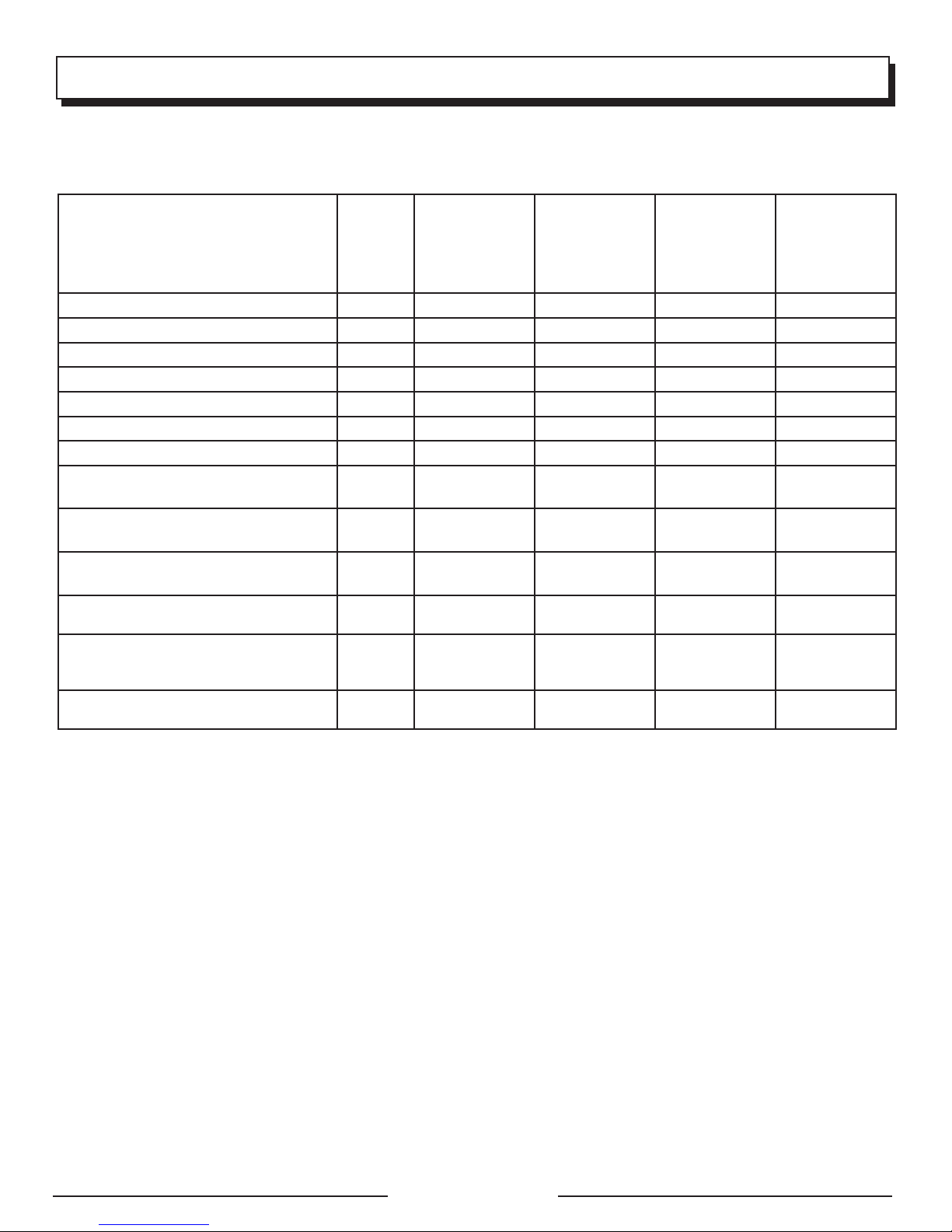
MANTENIMIENTO
PROGRAMA DE MANTENIMIENTO
NOTA: Si recibe un manual del motor para este generador en particular, respete el cronograma de mantenimiento que se
indique en el manual del motor y no la información de mantenimiento que figura a continuación.
Al cabo del
Antes de
cada uso
Revisar el lubricante del motor
Cambiar el lubricante del motor
Revisar el filtro de aire
Limpiar el filtro de aire
Cambiar el filtro de aire
Comprobar/ajustar la bujía
Reemplazar la bujía
Comprobar/limpiar la pantalla
parachispas
Limpiar el depósito y el filtro de
combustible
Comprobar de manguera de
combustible
Compruebe todas las conexiones de
mangueras
Inspeccione la respirador del vapor
del tanque de combustible (si está
instalada)
Inspeccione el depósito de carbón
(únicamente modelos CARB)
1 Estas tareas deben ser efectuadas sólo por el centro de servicio calificado.
NOTA: La frecuencia de mantenimiento debe ser mayor si se el generador se usa en zonas de mucho polvo.
Si el generador ha sobrepasado los valores máximos especificados en el cuadro, aun debe seguirse el programa
1
de mantenimiento de acuerdo con los intervalos allí recomendados.
primer mes o
20 horas de
funcionamiento
Cada 3 meses
o 50 horas de
funcionamiento
Cada 6 meses
o 100 horas de
funcionamiento
Cada año
o luego de
300 horas de
funcionamiento
Página 18 — Español
Page 44

CORRECCIÓN DE PROBLEMAS
PROBLEMA POSSIBLE CAUSE SOLUCIÓN
El motor no arranca. El interruptor de encendido y apagado está
en OFF (O) (apagado).
No hay combustible.
Gasolina pasada o agua pasada en la
gasolina.
Está bajo el nivel de lubricante.
Bujía defectuosa, sucia o con separación
incorrecta.
La palanca de anegador está en la posición
FUNCIONAMIENTO.
El motor almacenado sin tratamiento ni
vaciado de gasolina, o reabastecido de
gasolina de mala calidad.
Elemento de combustible obstruidos.
Ponga el interruptor de encendido y
apagado está en ON (I) (encendido).
Llene el tanque.
Drene todo el sistema y reabastézcalo con
combustible nuevo.
El motor posee un apagado por poco
aceite. Si el nivel del lubricante del motor es
bajo, debe llenarse antes de que la unidad
arranque. Revise el nivel del lubricante del
motor, y reabastézcalo si es necesario.
Reemplace la bujía.
Mueva el anegador de la palanca del
anegador hasta la posición ARRANQUE.
Vacíe el combustible y el carburador.
Reabastezca de gasolina fresca la unidad.
Comuníquese con un centro de servicio
calificado.
Cuesta trabajo arrancar el motor. Hay agua en la gasolina.
Está débil la chispa de la bujía.
Le falta potencia al motor. Está sucio el filtro de aire.
El motor almacenado sin tratamiento ni
vaciado de gasolina, o reabastecido de
gasolina de mala calidad.
No funciona el receptáculo de C.A. Está sobrecargado del generador.
Está defectuoso el dispositivo conectado.
El generador produce un ruido como de
“cascabeleo” o “explosiones”.
Si el problema persiste después de probar las soluciones mencionadas arriba, comuníquese con el servicio al cliente o con un centro
de servicio calificado para solicitar asistencia.
Un leve ruido ocasional de “cascabeleo” o
“explosiones” si la carga es pesada no debe
ser causa de preocupación. No obstante, si
tal cascabeleo o explosiones ocurren con
una carga normal a velocidad estable del
motor, el problema puede ser la marca de
gasolina utilizada.
Drene todo el sistema y reabastézcalo con
combustible nuevo.
Comuníquese con un centro de servicio
calificado.
Compruebe el elemento de filtro de aire.
Limpie o reemplace según sea necesario.
Compruebe el elemento de filtro de aire.
Limpie o reemplace según sea necesario.
Quite cargas y apriete el botón de reajuste.
Pruebe con un dispositivo diferente.
Cambie a una marca diferente de gasolina,
y asegúrese de que sea de un octanaje de
86 por lo menos. Si el problema continúa,
comuníquese con un centro de servicio
calificado.
AVISO:
Como propietario equipo, usted es responsable de que se realice el mantenimiento obligatorio que se indica en esta Mantenimiento.
Le recomendamos que guarde todos los comprobantes relacionados con el mantenimiento de su equipo. Negligencia o falta del
mantenimiento indicado puede aumentar las emisiones, reducir la eficiencia del combustible, perjudicar el funcionamiento, provocar
daños irreversibles al motor y anulará su garantía.
Página 19 — Español
Page 45
GARANTÍA
GARANTIA LIMITADA
COBERTURA DE LA GARANTÍA
OWT Industries, Inc., (la Compañía) garantiza al comprador minorista original que este Producto Black Max carece de
defectos en material y mano de obra, y acuerda reparar o reemplazar, a la entera discreción de la Compañía, cualquier
Producto defectuoso sin cargo en los siguientes períodos a partir de la fecha de la compra:
Dos años si el Producto se utiliza exclusivamente para fines personales, familiares o domésticos.
90 días si el Producto se utiliza para fines comerciales.
Esta garantía sólo es válida para los Productos vendidos dentro del territorio de los Estados Unidos de América, el
distrito de Columbia, Canadá, México, el Estado Libre Asociado de Puerto Rico, las Islas Vírgenes, Guam, la Zona del
Canal o Samoa Americana.
Esta garantía no es transferible y sólo cubre los daños derivados de defectos en material o mano de obra y no los
daños causados por el uso irracional, incluida la falta de mantenimiento razonable y necesario. Entre los artículos
que no cuentan con la cobertura de esta garantía, se encuentran:
Los gastos de transporte originados por el envío del producto a la Compañía o a su representante de servicio
autorizado para el mantenimiento incluido en la garantía, o por el envío al consumidor de productos reparados o
reemplazados; estos cargos corren por cuenta del comprador minorista original.
Motor. El Producto está equipado con un motor que cuenta con la cobertura exclusiva de otra garantía de su
fabricante. Consulte el manual del motor incluido con el Producto para obtener información sobre la garantía
correspondiente al motor.
Los daños causados por el maltrato, los accidentes, el uso indebido, la negligencia, la alteración, la modificación,
los efectos de la corrosión, la erosión, el desgaste normal o las reparaciones realizadas por personas ajenas a la
Compañía o a sus representantes de servicio autorizados.
La garantía queda anulada si el cliente no instala, mantiene o utiliza el producto respetando las instrucciones y las
recomendaciones de la Compañía, según se expresa en el manual del operador del Producto, o si el Producto se
utiliza como equipo de alquiler.
La Compañía no se hará cargo de las reparaciones o los ajustes al Producto, o de cualquier tarea o gasto que no sea
autorizado previamente por esta Compañía.
IMPORTANTE: A los componentes que esta garantía no cubra, los podrá cubrir una garantía adicional emitida
por el que fabricante del motor. consulte la garantía del fabricante del motor (si la hubiera) que se entregó con
el producto para conocer más detalles.
GUARDE SU COMPROBANTE DE COMPRA
Antes de que la Compañía o sus representantes de servicio autorizados puedan efectuar el servicio correspondiente
cubierto por la garantía del Producto, se solicitará como comprobante de compra una factura de compra con fecha,
un recibo de la caja registradora, etc. que incluya el número de serie y el modelo.
ESTA GARANTÍA LIMITADA PREVALECE SOBRE CUALQUIER OTRA GARANTÍA EXPRESA. CUALQUIER GARANTÍA
IMPLÍCITA DE COMERCIABILIDAD, IDONEIDAD PARA UN FIN ESPECÍFICO U OTRA QUE BRINDE COBERTURA
PARA ESTE PRODUCTO ESTARÁ LIMITADA EN DURACIÓN AL PLAZO DE ESTA GARANTÍA LIMITADA. EL SERVICIO
DE GARANTÍA DESCRITO ANTERIORMENTE ES EL ÚNICO RECURSO BAJO ESTA GARANTÍA. LA COMPAÑÍA NO
SERÁ RESPONSABLE DE CUALQUIER DAÑO ESPECIAL, INDIRECTO O CONSECUENTE. ALGUNOS ESTADOS NO
PERMITEN LIMITACIONES EN CUANTO A LA DURACIÓN DE UNA GARANTÍA IMPLÍCITA, O LA EXCLUSIÓN O LIMITACIÓN DE LOS DAÑOS INDIRECTOS O CONSECUENTES; POR LO QUE ES POSIBLE QUE LAS LIMITACIONES O
EXCLUSIONES ANTERIORES NO SE APLIQUEN EN SU CASO.
CÓMO OBTENER UN SERVICIO DE GARANTÍA
Para obtener el servicio de garantía: Llame sin cargo al 1-800-726-5760 o escriba a OWT Industries, Inc.,
P.O. Box 35, Hwy. 8, Pickens, SC 29671.
Para obtener el servicio de garantía fuera de los EE. UU., comuníquese con el establecimiento Black Max local.
EXCLUSIONES Y LIMITACIONES
Página 20 — Español
Page 46

GARANTÍA
DECLARACIÓN DE GARANTÍA LIMITADA AL MOTOR
OWT Industries, Inc., (la Compañía), garantiza al comprador minorista original que cada motor nuevo que se venda carecerá
de defectos en material y mano de obra bajo condiciones normales de servicio y uso durante el período mencionado abajo
a partir de la fecha de venta. La obligación de La Compañía bajo esta Garantía limitada cubre únicamente la reparación y
el reemplazo, a elección de La Compañía, de las partes que, luego de ser examinadas, resulten, a criterio de La Compañía
defectuosas en material o mano de obra. Una condición de la obligación deLa Compañía obligation under this Limited
Warranty that La Compañía, bajo esta Garantía Limitada será que esta empresa directamente o a través de uno de sus
Distribuidores o Centros de Servicio autorizados a realizar el servicio del motor en cuestión, reciban una notificación inmediata
de cualquier reclamo de la garantía y que el motor, o las partes presuntamente defectuosas, se envíen inmediatamente con el
transporte pagado por adelantado a dicho Distribuidor o Centro de Servicio para realizar la inspección y reparación. Todas las
reparaciones que califiquen bajo esta Garantía limitada deben ser realizadas por La Compañía, o uno de sus Distribuidores
o Centros de Servicios autorizados.
PERÍODOS DE GARANTÍA:
Garantía limitada de dos años del motor de gasolina 144F (privado o residencial)
Garantía limitada de 90 días de motores de gasolina 144F (comerciales).
La reparación o el reemplazo de las partes bajo esta Garantía limitada no extenderán el plazo de garantía del motor más allá
del plazo original establecido anteriormente.í
LIMITACIONES Y EXCLUSIONES: Esta Garantía limitada no cubrirá:
1 Reparaciones necesarias a causa de un período de almacenamiento prolongado, incluidos los daños ocasionados por el
combustible contaminado o alojado por mucho tiempo en el tanque de combustible, las tuberías o el carburador, las válvulas
pegajosas o la corrosión y el óxido en partes del motor.
2 Reparaciones necesarias debido al recalentamiento. (Generalmente provocado por la sobrecarga, obstrucción, daño o
ante la falta del volante, el ventilador, los conductos de entrada de aire, las aletas de enfriamiento o cubierta de paso de aire).
3 Desgaste propio del polvo o la arenilla ocasionado por el mantenimiento inadecuado del filtro de aire (que generalmente
provoca el desgaste de los pistones, los aros del pistón, los cilindros, las válvulas, las guías de las válvulas, el carburador u
otros componentes internos).
4 Piezas rotas o rayadas debido a un bajo nivel de lubricante, suciedad o un grado de lubricante inadecuado.
5 Servicios de mantenimiento normales y ajustes al motor, incluidos, entre otros, el ajuste de válvulas, el reemplazo normal
de artículos de servicio, combustible, lubricante, etc.
6 Cualquier motor que haya estado expuesto a la negligencia, al uso indebido, accidentes, al uso incorrecto o al exceso
de velocidad.
7 Cualquier motor que haya sido instalado, reparado o alterado por cualquier persona de manera tal que, según el criterio
exclusivo de la Compañía, se vea afectado su desempeño o fiabilidad.
8 Cualquier motor que haya sido montado o reparado con piezas o componentes que no hayan sido fabricados o aprobados
por la Compañía, y que, según el criterio exclusivo de esta empresa, afecten de modo adverso el desempeño o fiabilidad
del motor.
9 Circunstancias en las cuales el uso normal haya terminado con la vida útil de un componente o de un motor.
El cliente es responsable de todos los gastos de transporte incurridos ante la realización de tareas cubiertas por la garantía.
La Compañía se reserva el derecho de modificar, alterar o mejorar cualquier motor o pieza sin incurrir en ninguna obligación
de modificar o reemplazar las piezas o los motores vendidos anteriormente que no cuenten con dicha modificación, alteración
o mejora.
Ninguna persona está autorizada a otorgar cualquier otra garantía o a asumir una obligación adicional en nombre de La
Compañía, a menos que cuente con una autorización por escrito y firmada por un directivo de La Compañía.
ESTA GARANTÍA Y LA OBLIGACIÓN DE OWT INDUSTRIES, INC. MENCIONADA EN ESTE DOCUMENTO PREVALECE
SOBRE CUALQUIER OTRA GARANTÍA U OBLIGACIÓN DE CUALQUIER TIPO EXPRESADA O IMPLÍCITA, INCLUIDA
CUALQUIER GARANTÍA DE COMERCIABILIDAD O IDONEIDAD PARA UN FIN EN PARTICULAR. NO EXISTEN GARANTÍAS
QUE SE EXTIENDAN MÁS ALLÁ DE LA DESCRIPCIÓN ESPECIFICADA EN EL PRESENTE DOCUMENTO. EN NINGÚN
CASO, OWT INDUSTRIES, INC. SERÁ RESPONSABLE DE CUALQUIER DAÑO INDIRECTO O CONSECUENTE.
SI TIENE ALGUNA PREGUNTA CON RESPECTO A LOS DERECHOS Y LAS RESPONSABILIDADES
DE LA GARANTÍA, PÓNGASE EN CONTACT OWT INDUSTRIES, INC. AT 1-800-726-5760.
Página 21 — Español
Page 47

NOTAS
Página 22 — Español
Page 48
R
OPERATOR’S MANUAL
MANUAL DEL OPERADOR
SERVICE
CALIFORNIA PROPOSITION 65
WARNING:
This product, its exhaust, and
other substances that may become
airborne from its use contain
chemicals, including lead, known
to the State of California to cause
cancer, birth defects, or other
reproductive harm. Wash hands
after handling.
For parts or service, contact your service dealer. Please call 1-800-726-5760
or visit us online at www.b lackmaxtools.com for assistance. Be sure to provide
all relevant information when you call or visit. A replacement parts list is also
available online.
REPAIR PARTS
The item, manufacturing, and serial numbers of this product are found on a
plate or label attached to the housing. Please record these numbers in the
spaces provided below.
ITEM NO. __________________________________________________
MANUFACTURING NO. _____________________________________
DIGITAL INVERTER GENERATOR
GENERADOR DEL INVERSOR DE DIGITACES
BMi1000
CALIFORNIA - PROPUESTA DE
LEY NÚM. 65
ADVERTENCIA:
Este producto, su escape y otras
sustancias que puedan llegar a ser
aerotransportadas por su uso pueden
contener sustancias químicas
(incluido el plomo) reconocidas
por el estado de California como
causantes de cáncer, defectos
congénitos y otras afecciones del
aparato reproductor. Lávese las
manos después de utilizar el
aparato.
SERIAL NO. ________________________________________________
SERVICIO
Para obtener piezas o servicio, comuníquese con el centro de servicio. Para
asistencia, le suplicamos llamar al 1-800-726-5760 o visitar nuestro sitio en la red
mundial, en la dirección www.blackmaxtools.com. Asegúrese de proporcionar
todos los datos pertinentes al llamar o al presentarse personalmente. Una lista
de piezas de repuesto está también disponibles en línea.
PIEZAS DE REPUESTO
El número de artículo, el número de fabricación y el número de serie de este
producto se encuentra en una placa o etiqueta pegada a la caja del motor.
Le recomendamos anotar los números en los espacios suministrado abajo.
NÚMERO DE ARTÍCULO ____________________________________
NÚMERO DE FABRICACIÓN_________________________________
NÚMERO DE SERIE ________________________________________
991000572
3-21-16 (REV:03)
OWT INDUSTRIES, INC.
P.O. Box 35, Highway 8
Pickens, SC 29671 USA
1-800-726-5760
www.blackmaxtools.com
 Loading...