

Page 1
Installation and Operation Manual
HyperDeck
Disk Recorders
March 2020
English, 日本語, Français, Deutsch, Español, 中文,
한국어, Русский, Italiano, Português and Türkçe.
Page 2
Languages
To go directly to your preferred language, simply click on the hyperlinks listed in the
contents below.
English 3
日本語 82
Français 162
Deutsch 244
Español 324
中文 404
한국어 484
Русский 564
Italiano 644
Português 724
Türkçe 804
Page 3

English
Welcome
We hope you share our dream for the television industry to become a truly creative industry by allowing
anyone to have access to the highest quality video.
Our range of HyperDeck disk recorders have made it easier and more affordable than ever to record
and play back full 10 Bit uncompressed video and now Ultra HD! HyperDeck records directly to
removable 2.5" Solid State Disks (SSDs) and SD cards that are getting bigger, faster and more affordable
every day. It’s incredible that you can now record and play the most amazing quality video onto
something so small thousands of times without any degradation in quality!
SSDs and SD cards can also be connected to any computer for immediate editing and fast transfer of
your media. With no moving parts, they are unbelievably robust and can handle harsh conditions that
would destroy conventional hard drives and videotapes!
You can bypass unwanted camera compression and record directly from HDMI or SDI cameras and
even connect to any HDMI or SDI monitor for instant playback. The HyperDeck Studio Mini model is
a small and portable, modular Ultra HD disk recorder that records on tiny SD cards. With HyperDeck
Studio Pro, you can connect analog sources and also record and play back Ultra HD with 6G-SDI. The
HyperDeck Studio 12G model can record even higher frame rates
in Ultra HD up to 60 fps!
If you need longer recording times, then HyperDeck also records and plays back AppleProRes and
Avid DNx files. These 10 Bit quality codecs retain fantastic picture quality and increase the recording
length of your media by more than 5 times!
This instruction manual contains all the information you need to start using your HyperDeck disk
recorder. For uncompressed recording you need to use an SSD that supports the required data speed
and we are continually adding details on our website of new SSDs that we have tested.
Please check the support page at www.blackmagicdesign.com for the latest version of this manual and
updates to the HyperDeck software. Keeping your software up to date will always ensure you get all the
latest features. When downloading software, please register with your information so we can keep you
updated when new software is released. We are constantly working on new features and improvements,
so we would love to hear from you!
Grant Petty
CEO Blackmagic Design
Page 4

Contents
HyperDeck Disk Recorders
Getting Started 5
Recording 7
Playback 10
HyperDeck Status Indicators 13
About SSDs and SD Cards 14
Blackmagic HyperDeck Setup 21
Selecting Your Video Format 22
Choosing a Codec 23
Control Panel Display Menu 26
Trigger Recording 27
RS-422 Control 29
Transferring Files over a Network 35
Connecting to an ATEM Switcher 37
Understanding Post
Production Workflows 38
Using DaVinci Resolve 39
Adding Titles 44
Color Correcting your Clips with
the Color Page 45
Adding a Power Window 48
Using Plugins 50
Mixing Your Audio 51
Adding VFX and Compositing on
the Fusion Page 55
Mastering Your Edit 64
Quick Export 64
The Deliver Page 65
Developer Information 66
Blackmagic HyperDeck Ethernet
Protocol 66
Protocol Commands 66
Protocol Details 69
Project Manager 39
Editing with the Cut Page 40
Adding Clips to the Timeline 43
Editing Clips on the Timeline 44
Help 78
Regulatory Notices 79
Safety Information 80
Warranty 81
Page 5
Getting Started
POWER REMOTE
IN
SD/HD/3G/6G-SDI IN TIMECODE
IN OUT CH 1 CH 2 CH 1 CH 2
OUT
IN A
Y IN B-Y IN R-Y IN R-Y OUT REF IN
L
R
STEREO IN
B-Y OUTY OUT
IN B IN C IN D OUT A OUT B OUT C OUT D MON OUT
ETHERNET
HDMI
PUSH
SD/HD/3G/6G-SDI OUT
REF OUT
REF INETHERNET PoE+
SDI OUT
SDI IN
HDMI OUT
REMOTE IN
BA
USB-C
Getting Started with Blackmagic HyperDeck
Getting started with your HyperDeck disk recorder is as easy as connecting power, plugging in
your video sources and destination equipment to your HyperDeck’s inputs and outputs and
inserting your SSDs or SD cards.
Plugging in Power
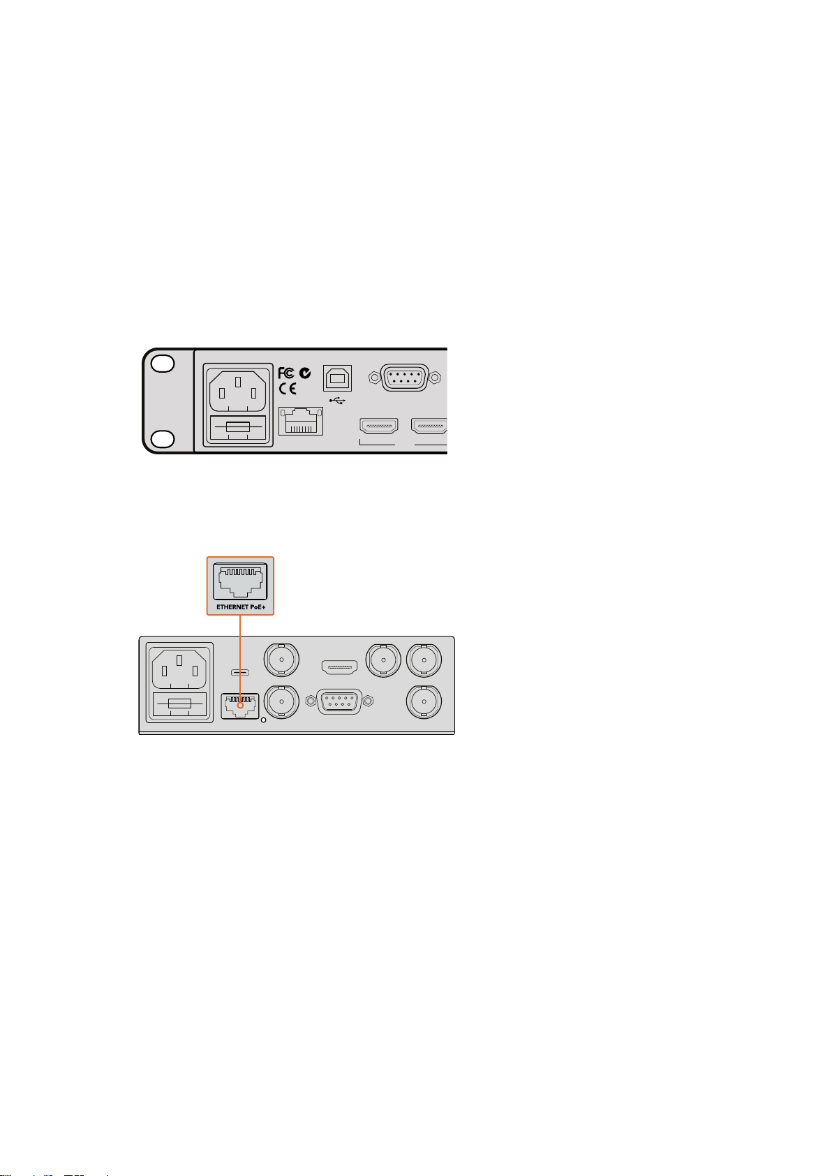
Simply plug a standard IEC cable to your HyperDeck’s power input on the rear panel.
Connect power to your HyperDeck Studio using
a standard IEC power cable
You can also power your HyperDeck Studio Mini via Ethernet by plugging into a compatible
Ethernet switch that supports PoE+, or ‘power over Ethernet plus’.
Connect power to your HyperDeck Mini using a standard IEC power cable.
Power can also be supplied via a PoE+ compatible Ethernet switch.
Plugging in Video and Audio
Plug your source video to the SDI or HDMI inputs, and your destination equipment to the
SDI or HDMI outputs.
HyperDeck Studio 12G has 12G-SDI connectors so you can input or output Ultra HD up to
2160p60 using a single BNC cable.
HyperDeck Studio Pro provides additional inputs and outputs for connecting video equipment
that supports single link, dual link or quad link Ultra HD.
5Getting Started
Page 6
Plugging in Analog Audio and Timecode on HyperDeck Studio Pro
IN OUT CH 1 CH 2 CH 1 CH 2
ANALOG AUDIO IN ANALOG AUDIO OUT
L
R
STEREO IN
PUSH PUSH
PUSH
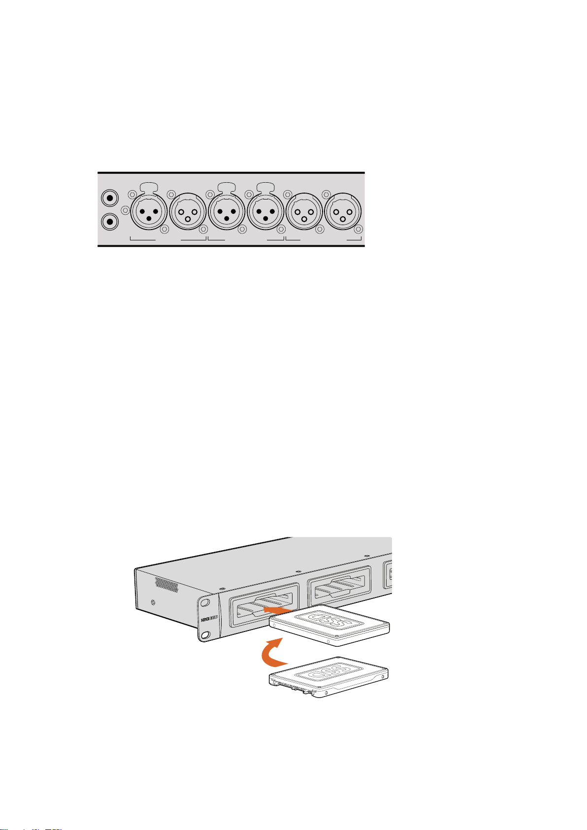
If you want to connect analog audio sources to HyperDeck Studio Pro, plug into the XLR or RCA
connectors. To select your desired audio input, simply press the ‘input’ button on the front
control panel to cycle through combinations of video and audio inputs. For example, SDI + XLR,
SDI + RCA, and more. External timecode can also be connected to and from your HyperDeck
Studio Pro via the timecode XLR input and output connectors.
HyperDeck Studio Pro lets you plug in external analog audio and timecode
via the rear panel XLR connectors. You can even plug in analog audio from
audio equipment such as iPods and HiFi systems via the RCA inputs.
Plugging in SSDs and SD Cards
All HyperDeck models ship ready to record immediately without having to configure any
settings. All you need is a formatted SSD or SD card.
You can easily format media via the front LCD based menu settings. You can also format using
a computer.
Refer to the ‘About SSDs and SD Cards’ section in this manual for more information on how to
format, the types of media that are best for recording video and a list of recommended drives
and cards.
To plug in an SSD:
1 Hold a 9.5mm SSD with the connection pins facing the bottom and aligned with your
HyperDeck’s drive bay. Gently push the SSD into the drive bay until you feel it slot
into place.
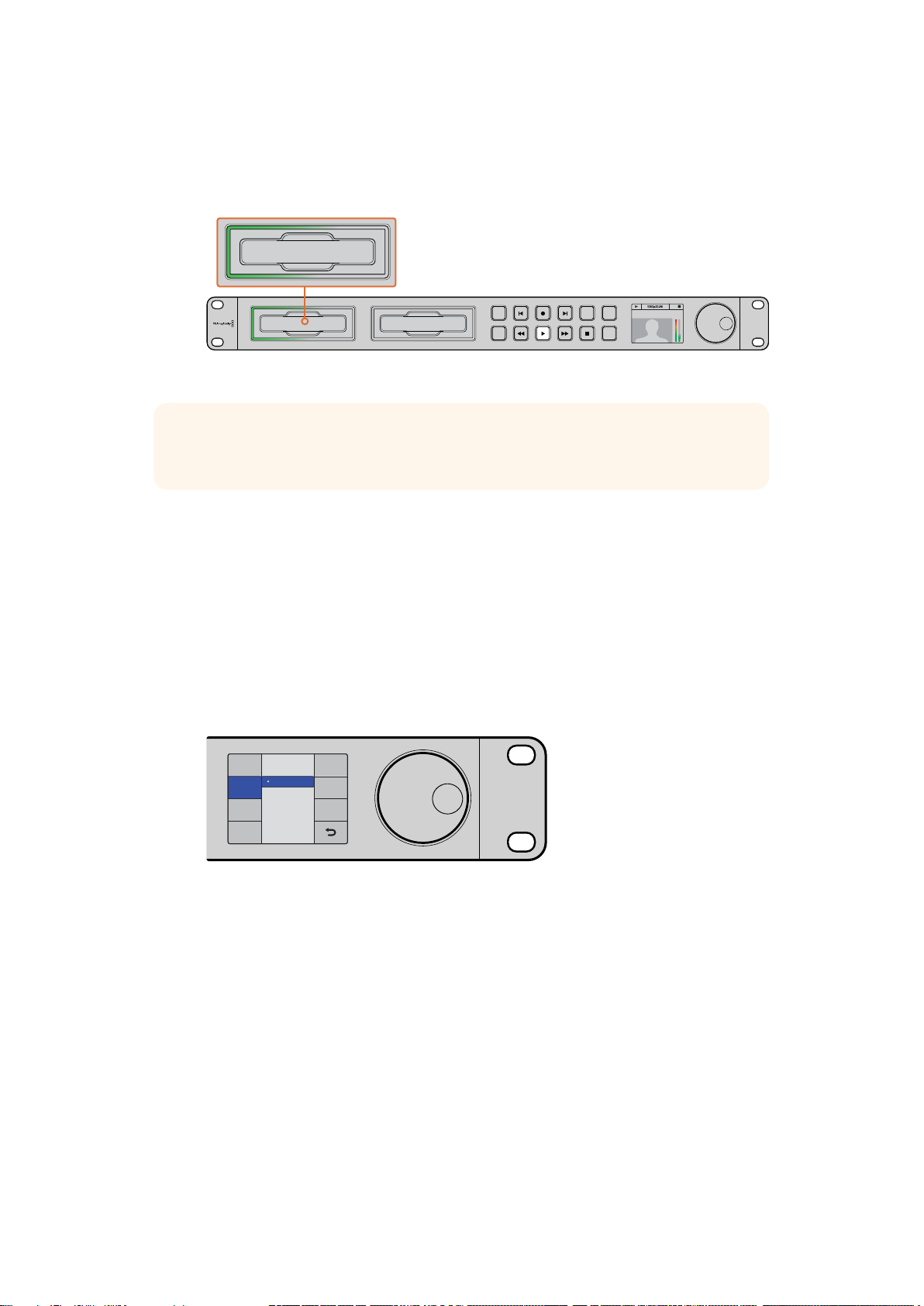
2 Your HyperDeck will verify the SSD. This is shown by an illuminated green light
surrounding the drive bay. When the light or indicator turns off and the ‘stop’ button
on the control panel is illuminated, your HyperDeck is ready to record.
Hold your SSD with the connection pins facing the bottom, aligned with your HyperDeck’s
drive bay and gently push the SSD into the drive bay until you feel it slot into place
6Getting Started
Page 7
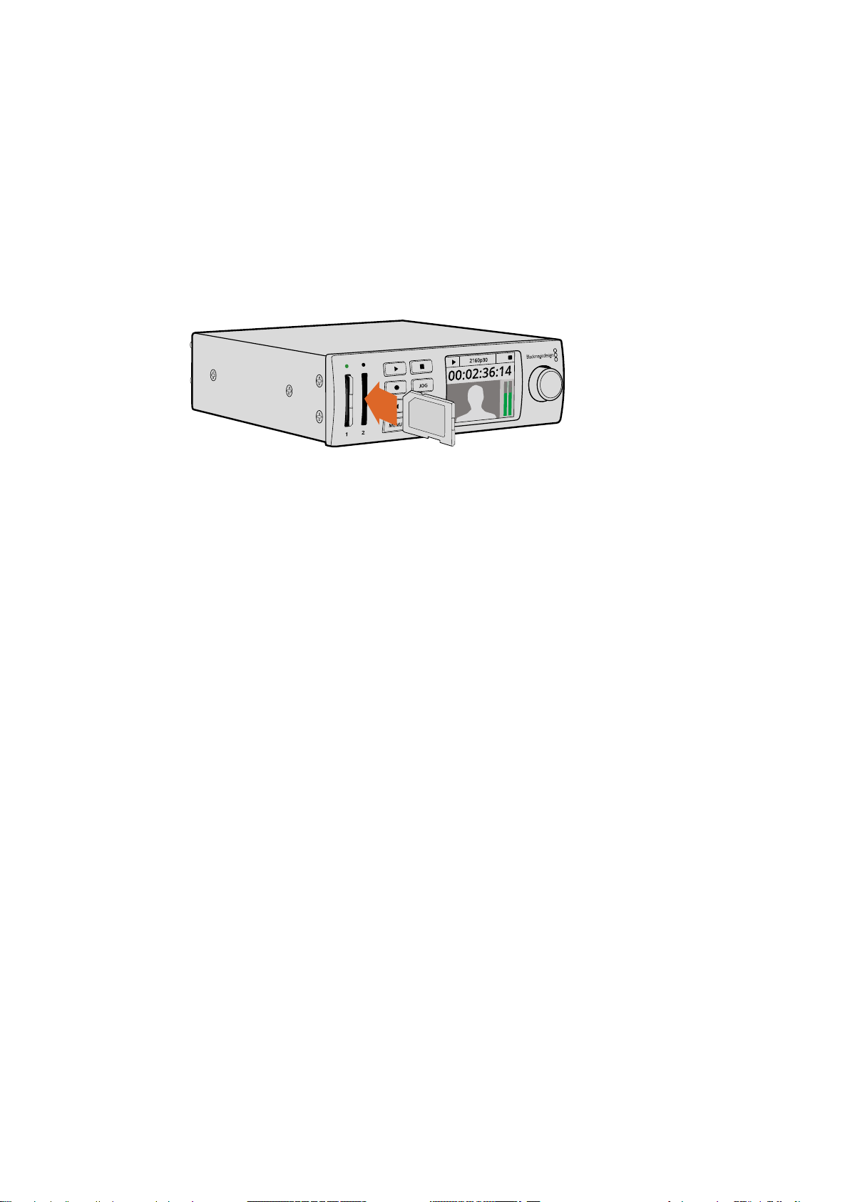
To plug in an SD card:
Card 1
1 Hold the SD card with the gold connectors facing your HyperDeck’s LCD and align it
with the media slot. Now gently push the card into the slot until you feel it lock firmly
into place.
2 Your HyperDeck will verify the SD card. This is shown by an illuminated green indicator
above the SD card slot. When the indicator turns off and the stop button on the control
panel is illuminated, your HyperDeck is ready to record.
To remove the card, gently push until you feel it click, then release. The card will eject a short
distance, allowing you to hold the edge of the card and remove it from the slot.
Gently push the SD card into the slot until you feel it click into place
Recording
Recording Ultra HD and HD video with HyperDeck
HyperDeck models that support Ultra HD video record compressed Ultra HD using Apple
ProRes, plus Avid DNxHR on HyperDeck Studio 12G and HyperDeck Studio Mini. All HyperDeck
models can record HD video using ProRes and DNxHD 220x codecs. HyperDeck Studio
models that record on SSDs can also record uncompressed HD.
Recording Video with HyperDeck Studio Mini
HyperDeck Studio Mini can record compressed HD and Ultra HD video up to 2160p30
via 6G-SDI.
To record video:
1 Insert your formatted SD card into either of the SD card slots. The indicator above the
slot will illuminate green as your HyperDeck reads the card. When the indicator turns
off, HyperDeck Studio Mini is ready to record.
2 HyperDeck Studio Mini automatically detects when SDI video is connected and
displays the image on the control panel LCD.
If you want to change the codec, you can choose from a variety of codecs using the
control panel LCD menu or the Blackmagic HyperDeck Setup utility software. For more
information, refer to the ‘control panel display menu’ section, or ‘Blackmagic HyperDeck
Setup/selecting your video format’.
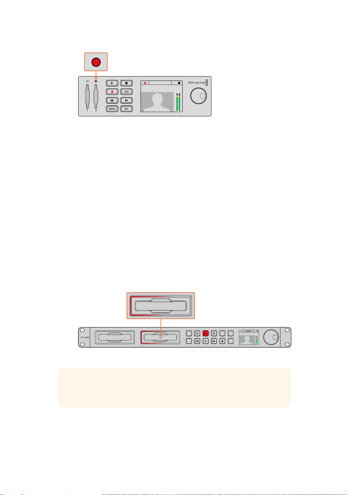
3 Press the ‘record’ button and the indicator above the slot will illuminate red.
As your HyperDeck is recording, the slot indicator on the control panel LCD will
alternate between displaying the active slot, and record time remaining on the card.
4 Press the ‘stop’ button to finish recording.
7Recording
Page 8
2160p30
INPUT
DISP
SET
REM
JOG
01:42:56:12
SSD
2
Card 2
01:23:47:08
The indicator above the SD card slot
illuminates red when recording video
Recording Video with HyperDeck Studio SSD Models
1 Insert your formatted SSD into either SSD slot. The LED strip surrounding the drive
will illuminate green as HyperDeck reads the disk. When the slot light turns off,
yourHyperDeck is ready to record.
2 Press the input button on the control panel to cycle through your HyperDeck’s inputs.
When your connected source is selected, it will appear on the control panel LCD.
For HyperDeck Studio Pro, pressing the input button will also cycle through
combinations of video and audio connections, for example SDI + SDI, SDI + XLR,
andSDI + RCA. This lets you record SDI or HDMI video with external audio.
If you want to record using a different codec, you can choose from a variety of codecs
using the control panel LCD menu or the HyperDeck Setup utility software. See the
‘control panel display menu’ section, or ‘Blackmagic HyperDeck Setup/selecting your
video format’ section for more information.
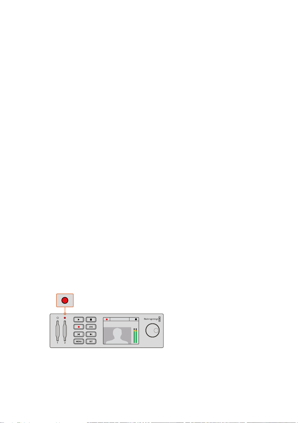
3 Press the ‘record’ button to start recording instantly. A looping red light on the SSD slot
indicates the SSD is recording.
4 Press the ‘stop’ button to finish your recording.
2
INPUT
DISP
SET
REM
JOG
01:42:56:12
SSD
On HyperDecks with SSD slots, the slot indicator will illuminate red to show the unit is recording
TIP If HyperDeck records from a video source that contains closed caption data,
theQuickTime or MXF movie will be recorded as well as a separate .MCC file
containing the closed caption data.
8Recording
Page 9
01:42:56:12
SSD
2
01:42:56:12
21
MENU
INPUT
DISP
SET
REM
JOG
STUDIOSTUDIO PRO STUDIO 12G
IN OUT
REF INMON OUTOUT 2OUT 1LOOP OUTIN
MENU
INPUT
DISP
SET
REM
JOG
Recording using Dual Media Slots
When there is less than 3 minutes of record time remaining on your SD card or SSD,
thetimecode counter on your HyperDeck’s LCD will turn red and the ‘stop’ button will
flash slowly.
This also means there is no second disk with space that recording can continue onto. In this
case, you simply need to insert a disk with space so recording can continue. Once you insert a
blank disk into the slot that’s not being used for recording, the slow flashing will stop and this
means HyperDeck can continue to record, because this second disk has been checked ok and
there is space to keep recording.
If you have less than three minutes
of recording time left on your
current disk and no formatted
media in yourHyperDeck’s
second slot, the timecode
indicator will turn red indicating
your recording is about to stop.
If there is space on a formatted
disk in the second slot, HyperDeck
will display an icon in the top right
corner to indicate that recording
will automatically switch over
once the current disk is full.
If you want to change the disk you are recording to at any time, and you have a second disk that
has free space, then simply hold down the record button and the recording will move from the
current disk to the second disk. This is very useful when you want to get that disk out of the
HyperDeck without pausing recording. This can happen during live events when you need to
get an important recording out to another location, but you don’t want to miss anything and you
don’t want to stop recording.
If the ‘record’ button flashes quickly, this means the disk is not fast enough for sustained
recording. In this case, if you are recording uncompressed HD, we recommend changing to a
compressed recording format such as ProRes or DNxHD, or if you are recording compressed
video and the record button flashes quickly, try using faster recommended media.
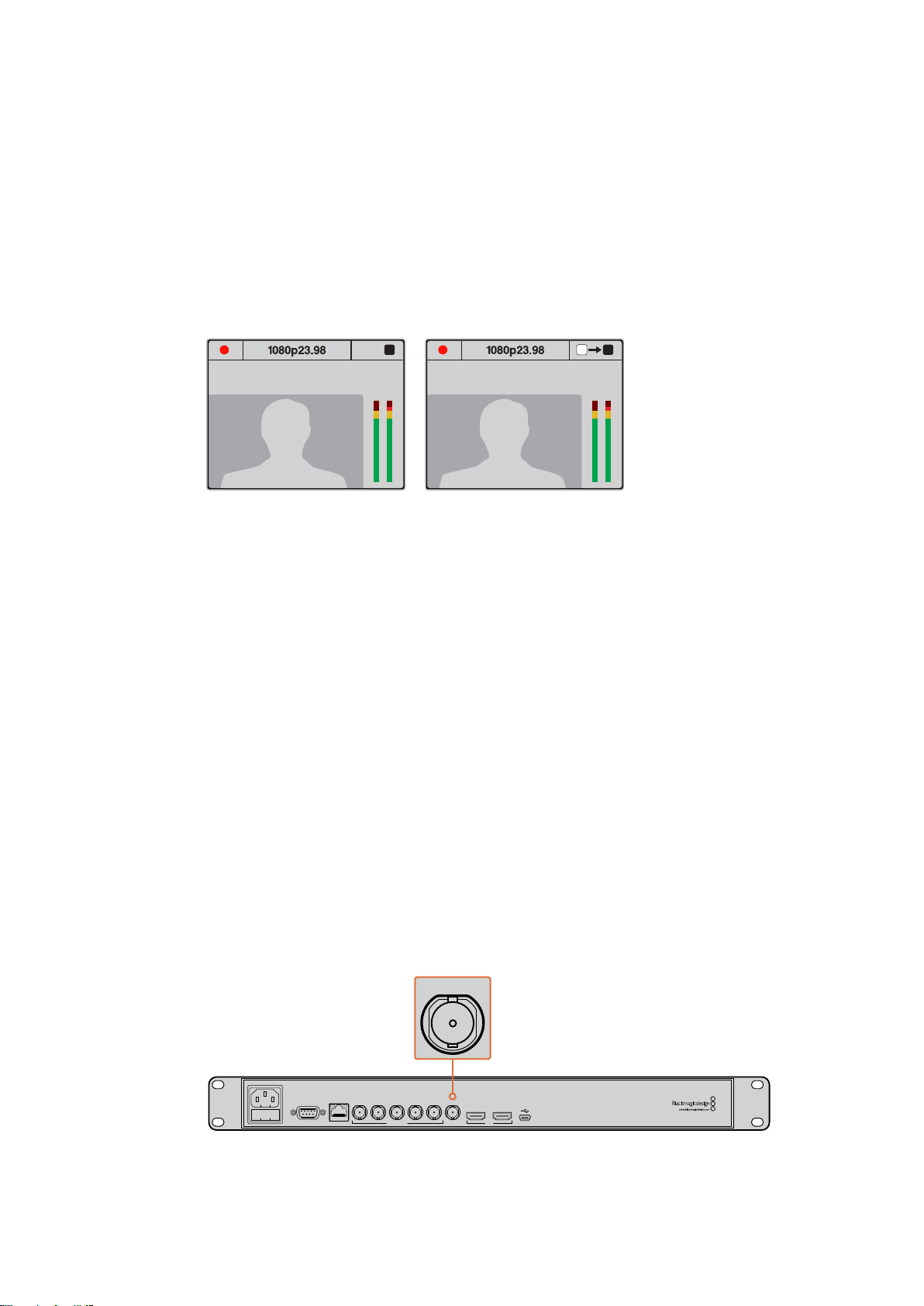
Ref Input
If your HyperDeck has a reference input, it can accept black burst and tri-level sync signals from
a sync generator. Connect a reference source to this input if you want to synchronize
HyperDeck with other video equipment, such as a production switcher.
If your HyperDeck has a reference input, you can sync your HyperDeck with other video equipment
REMOTE ETHERNET SD/HD/3GHD-SDI HDMI
REF INMON OUTOUT 2OUT 1LOOP OUTIN
IN OUT
9Recording
Page 10
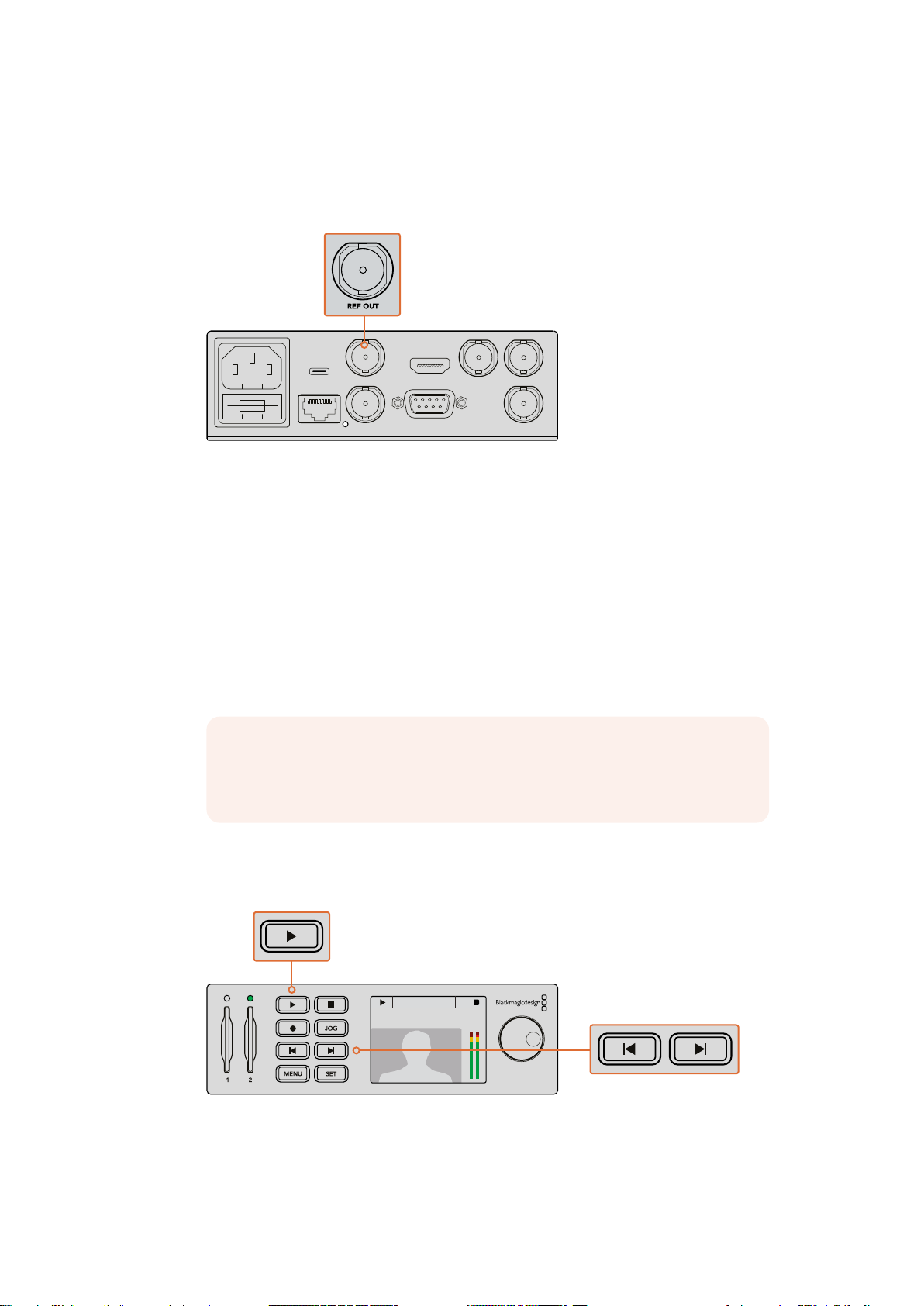
Ref Output
REF OUT
REF INETHERNET PoE+
SDI OUT
SDI IN
HDMI OUT
REMOTE IN
BA
USB-C
01:23:47:08
1080p59.94 Card 2
1080p59.94 Card 2
The reference output on HyperDeck Studio Mini lets you connect an internally generated black
burst or tri-level sync signal to other video equipment if you want to synchronize other
equipment with your HyperDeck.
On HyperDeck Studio Mini you can sync other video equipment
with your HyperDeck using the reference output
Playback
Playing Video with HyperDeck
1 Press the ‘play’ button once for instant playback and you’ll see your video on the LCD,
and any displays connected to your HyperDeck’s video outputs. When a clip is playing,
pressing ‘play’ again will loop it continuously. On HyperDeck Studio Mini, pressing play
a third time will let you loop all recorded clips.
NOTE With HyperDeck Studio Pro, you can choose to play back Ultra HD
using single link, dual link or quad link outputs. Refer to ‘Ultra HD Playback on
HyperDeck Studio Pro’ later in this section.
2 To skip to the next clip, press the ‘next clip’ button on the control panel.
3 Press ‘previous clip’ once to go to the start of the current clip or press twice to skip
back to the start of the previous clip.
1080p59.94 Card 2
01:23:47:08
Press the play button on your HyperDeck’s control panel
to play back a clip, and press the forward or reverse skip
buttons to restart the current clip or skip to a different one
10Playback
Page 11
If the play button flashes on HyperDecks that record on SSDs, this means the disk is not fast
01:42:56:12
SSD
2
INPUT
DISP
SET
REM
JOG
01:42:56:12
SSD
2
INPUT
DISP
SET
REM
JOG
2160p SDI Out
Dual 3G-SDI
Quad HD-SDI
Video In
4K SDI Out
Single 6G-SDI
enough and playback cannot keep up. We recommend you change to a compressed recording
format such as ProRes or DNxHD, or use a faster recommended SSD for uncompressed or
UltraHD recording.
SSD slots have rotating LEDs to show the unit is in playback mode
TIP If you play back a video clip that has an associated .MCC file, the closed caption
data will be played out with the video via the SDI output of your HyperDeck.
Ultra HD Playback on HyperDeck Studio Pro
HyperDeck Studio Pro can play back Ultra HD video via single link 6G-SDI, dual link 3G-SDI,
and quad link HD-SDI.
To select your desired Ultra HD playback output:
1 Press the ‘disp’ button to open the control panel LCD menu.
2 Using the jog/shuttle wheel and ‘set’ button, select ‘video’, then ‘2160p SDI out’.
3 Select your desired output type and press ‘set’ to confirm. Press the ‘disp’ button to
close the menu.
For HyperDeck Studio Pro, you can choose between single link 6G-SDI,
dual link 3G-SDI or quad link HD-SDI for Ultra HD playback
Jog or Shuttle
You can use the jog or shuttle wheel to shuttle to a particular section at variable speeds.
The more you turn it forwards or backwards, the faster your HyperDeck Studio will play through
your video. Once you’ve found the section you want to review, press ‘play’ to resume
normal playback.
If you want to slowly jog through your video frame by frame, press the ‘jog’ button once to
enable jog operation. Turning the jog or shuttle wheel in the desired direction will then jog
through your video. Pressing the ‘jog’ button again will return the wheel to shuttle operation.
11Playback
Page 12
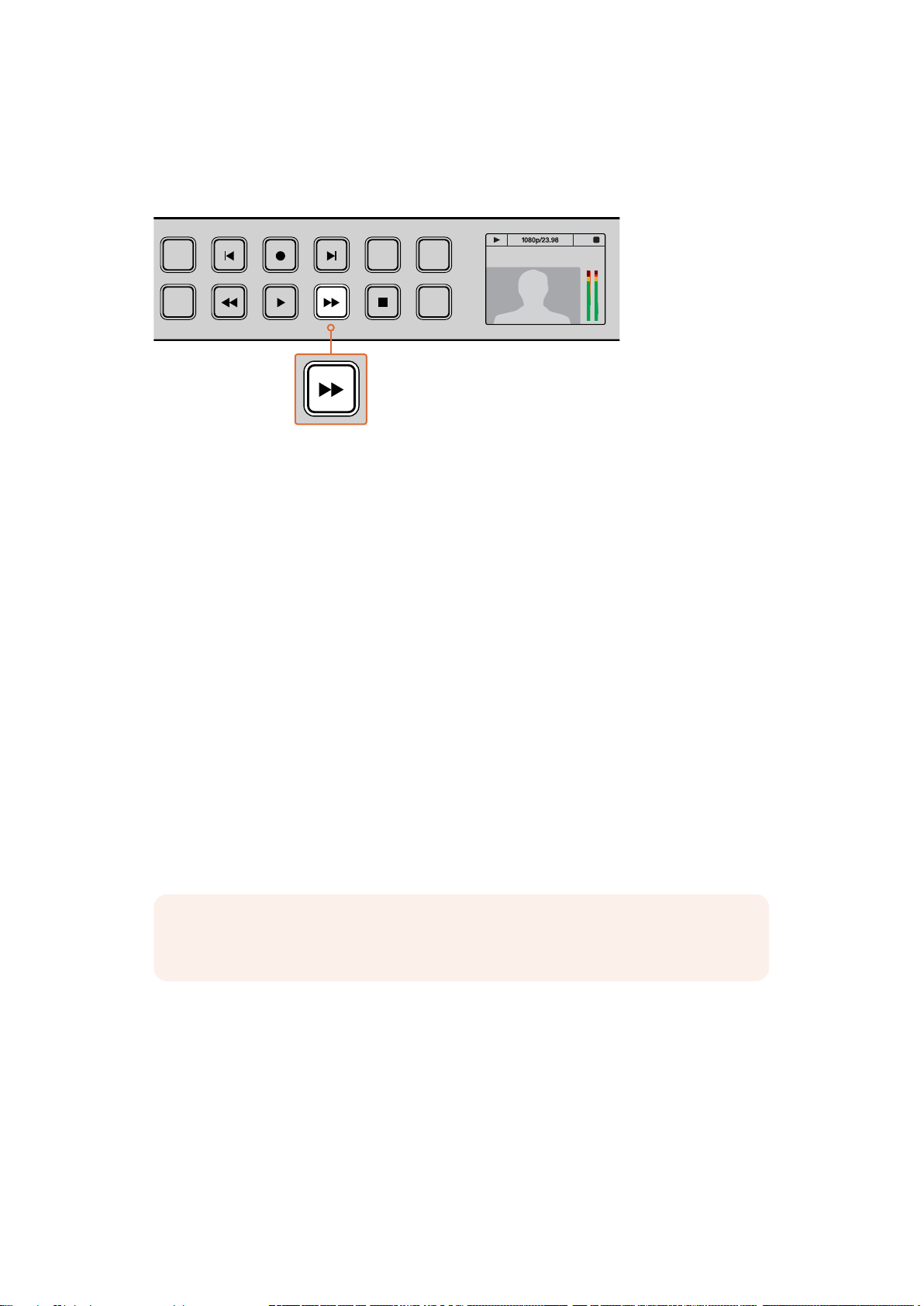
If your HyperDeck has ‘reverse’ or ‘fast forward’ buttons, you can press these buttons to play
INPUT
REM
JOG
01:42:56:12
SSD
2
through the clip at 2x speed. Press the ‘reverse’ or ‘fast forward’ buttons again and the speed
will increase to 4x and then 8x. Once you’ve found the section you want to review, press ‘play’
to resume normal playback.
2
SSD
DISP
INPUT
REM
01:42:56:12
SET
On HyperDecks with fast forward and reverse buttons, press the buttons repeatedly
to gradually shuttle playback forwards and backwards at faster speeds
JOG
HDR Playback on HyperDeck Studio 12G
HyperDeck Studio 12G is capable of playing back HDR wide gamut video content. This lets you
monitor HDR video on an HDMI TV or SDI monitor. For example, you may have HDR files you
have exported from a DaVinci Resolve workstation and want to view them on a larger screen
or HDMI projector.
Your HyperDeck will automatically read the metadata in the clip file and select the
corresponding HDR output format.
While the auto setting will be successful most of the time, some files may not include the
required metadata, and this may affect how the brightest regions of your image will be
displayed. If the image does not appear as expected, you can set the correct output format
using the ‘HDR’ LCD menu.
To set the HDR output format:
1 Press the ‘menu’ button to open the LCD menu.
2 Navigate to the ‘video’ menu and select ‘HDR’.
3 Select the video clip’s corresponding HDR output format from the list. For example, if
your clip was encoded for HDR 10 using ST2084 at 2000 nits, select ST2084 (2000).
NOTE For HDR playback to work as expected, the monitor or HDMI projector connected
to your HyperDeck Studio 12G must also be capable of displaying HDR content.
The HDR output settings available are:
Auto
Auto is the default setting that will let HyperDeck automatically select the output format
that conforms to the clip’s HDR metadata.
Rec.709
For high definition video using standard dynamic range.
12Playback
Page 13
Rec.2020 SDR
This setting is used for Ultra HD video using standard dynamic range.
HLG
HLG stands for ‘hybrid log gamma’. This format allows HDR video to be played back on
HDR capable TVs and monitors, including those that support up to Rec.2020 SDR.
The following settings support the Rec.2020 color gamut, plus PQ, or perceptual quantizer
published as SMPTE ST2084. PQ is the function of wide gamut HDR that allows for the display
of brighter images. Luminance values in candelas per meter squared, for example 1000 cd/m
2
indicate the maximum luminance per square meter supported by the corresponding format.
ST2084 (300)
2
300 cd/m
luminance.
ST2084 (500)
2
500 cd/m
luminance.
ST2084 (800)
2
800 cd/m
luminance.
ST2084 (1000)
2
1000 cd/m
luminance.
ST2084 (2000)
2
2000 cd/m
luminance.
ST2084 (4000)
2
4000 cd/m
luminance.
HyperDeck Status Indicators
Status Indicators
When recording or playing video with HyperDeck, any information you need to know is
displayed on the unit itself via LED indicators for each media slot and the built in LCD.
Media Slot Indicators
When you first power on HyperDeck, or any time you insert an SSD or SD card, the slot
indicator will illuminate green while checking the media and then switch off. If the disk has
not been formatted correctly, or fails to work, the slot will illuminate solid red until the disk is
removed. In this case, check if the disk is formatted correctly and also check that it works
with a computer.
2160p30
Card 2
01:23:47:08
HyperDeck’s media slot indicators illuminate to let you know the status of thedisk,
for example red when recording, and green during playback
13HyperDeck Status Indicators
Page 14
Control Panel LCD
01:42:56:12
SSD
1
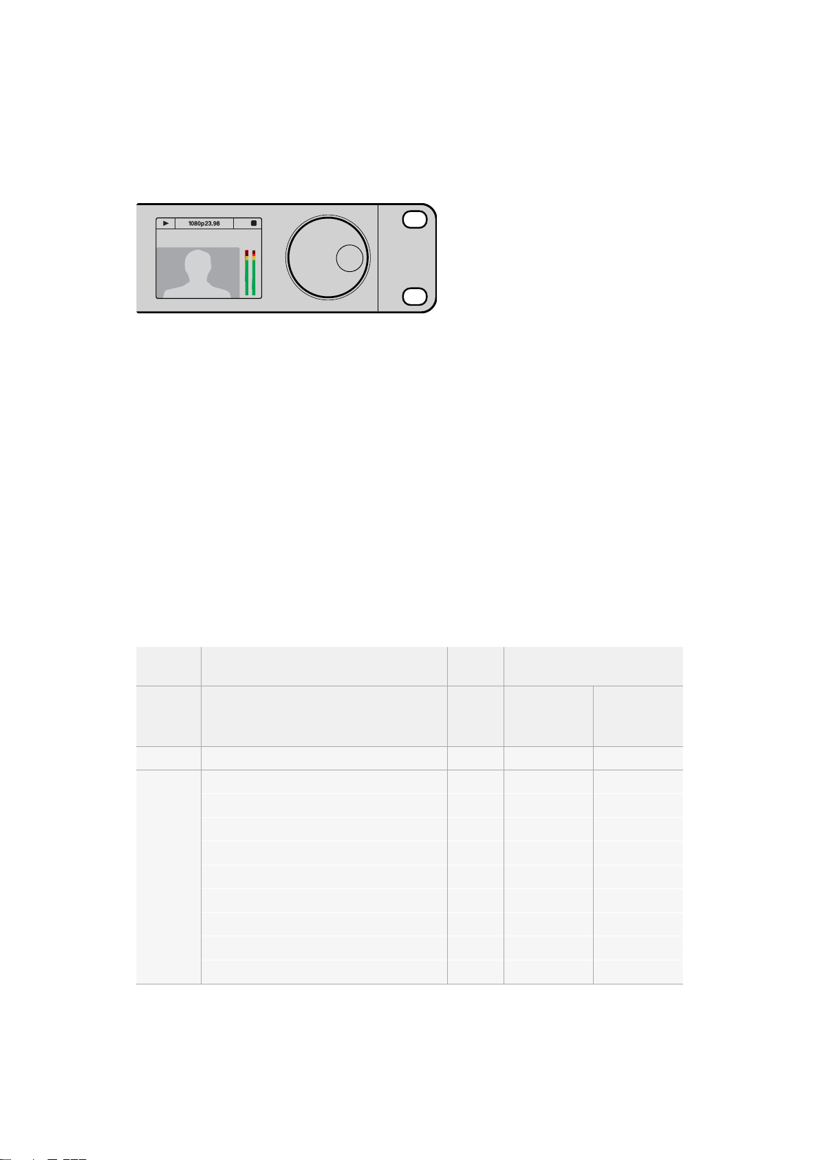
HyperDeck Disk Recorders feature an LCD that not only shows your video but also displays
status information such as video format and frame rate, record, playback and jog modes, the
active media slot as well as timecode and audio levels.
HyperDecks have a built in LCD that shows your
video as well as status information
About SSDs and SD Cards
Choosing a Fast SSD
When working with high data rate video it’s important to carefully check the SSD you would
like to use. This is because some SSDs can have up to 50% lower write speed than the
manufacturer’s claimed speed, so even though the disk specifications claim an SSD is fast
enough to handle video, in reality the disk is not fast enough for real time video recording.
Hidden data compression mostly affects recording and often these disks can still be used for
real time playback.
In our testing, we have found larger newer models of SSD and larger capacity SSDs are
generally faster. SSDs recommended for use with HyperDeck for uncompressed 10 Bit HD and
ProRes or DNxHR Ultra HD video recording include:
Brand SSD Name/Model Number Storage Supported Formats
10-bit
uncompressed
HD and Ultra HD
ProRes or DNxHR
ADATA XPG SX900 256GB Yes Yes
250 GB AV Pro (not HyperDeck Shuttle) 250GB Yes Yes
500 GB AV Pro (not HyperDeck Shuttle) 500GB Yes Yes
AVP250MK3 AP2A4CT 250GB Yes Yes
AVP500MK3 A2GMX52 500GB Yes Yes
Angelbird
AV PRO XT 500GB Yes Yes
AV PRO XT 1TB Yes Yes
AV PRO XT 2TB Yes Yes
AV PRO 250GB Yes Yes
AV PRO 500GB Yes Yes
HD ProRes
and DNxHD
14About SSDs and SD Cards
Page 15
Brand SSD Name/Model Number Storage Supported Formats
10-bit
uncompressed
HD and Ultra HD
ProRes or DNxHR
HD ProRes
and DNxHD
Crucial
Digistor
Intel
Kingston
M4 (firmware 009 only) CT512M4SSD2 512GB No Yes
M4 (firmware 000F only) CT256M4SSD2 256GB No Yes
4K Professional Video Series (DIG-PVD1000, preformatted ExFat)
Professional Video Series (DIG-PVD240S, preformatted ExFat)
Professional Video Series (DIG-PVD480S, preformatted ExFat)
1TB Yes Yes
240G B Yes Yes
480GB Yes Yes
335 Series SSDSC2CT240A4K5 240GB Yes Yes
520 Series SSDSC2CW240A310 240GB Yes Yes
520 Series SSDSC2CW480A310 480GB Yes Yes
530 Series SSDSC2BW180A401 180GB Ye s Yes
530 Series SSDSC2BW240A401 240GB Ye s Yes
HyperX 3K SH103S3/240G 240GB Ye s Yes
Now KC300 SKC300S37A/240G 240G B Yes Yes
HyperX 3K SH103S3/480G 480GB Yes Yes
HyperX Savage SHSS37A/120G 120GB Yes Yes
HyperX Savage SHSS37A/240G 240GB Ye s Yes
HyperX Savage SHSS37A/480G 480GB Yes Yes
HyperX Savage SHSS37A/960G 960GB Yes Yes
KC400 128GB Yes Yes
KC400 256GB Yes Yes
OCZ Agility 3 AGT3-25SAT3-240G 240GB No Yes
Mercur y Extreme Pro 6G OWCSSD7P6G120 120GB Yes Yes
OWC
Mercur y Extreme Pro 6G OWCSSD7P6G240 240GB Ye s Yes
Mercur y Extreme Pro 6G OWCSSD7P6G480 480GB Ye s Yes
Prevail SSD9SC240GCDA-PB 240G B Yes Yes
PNY
Prevail SSD9SC480GCDA-PB 480GB Yes Yes
XLR8 SSD9SC480GMDA-RB 480GB Yes Yes
15About SSDs and SD Cards
Page 16
Brand SSD Name/Model Number Storage Supported Formats
10-bit
uncompressed
HD and Ultra HD
ProRes or DNxHR
HD ProRes
and DNxHD
Samsung
Sandisk
Sony
850 Pro MZ-1T0BW, spacer required) - not
compatible with HyperDeckShuttle
850 Pro MZ-7KE256BW, spacer required 256GB Yes Yes
850 Pro MZ-7KE512BW, spacer required 512GB Yes Yes
860 EVO - not compatible with HyperDeck
Shuttle
860 EVO - not compatible with HyperDeck
Shuttle
860 EVO V-NANDMZ-76E250 250GB Yes Yes
860 EVO V-NAND MZ-76E1T0 1TB Yes Yes
860 EVO V-NAND MZ-76P256 256GB Yes Yes
860 EVO V-NAND MZ-76P512 512GB Yes Yes
860 EVO V-NAND MZ-76P1T0 1TB Yes Yes
860 EVO V-NAND500GB MZ-76E500 500GB No Yes
850 Pro 2TB Yes Yes
Extreme SDSSDX-240G-G25 240GB Ye s Yes
Extreme SDSSDX-480G-G25 480GB Yes Yes
Extreme SDSSDX-120G-G25 120GB No Yes
G series Professional SSD SV-GS48 480GB Yes Yes
G series Professional SSD SV-GS96 960GB Yes Yes
1TB Yes Yes
2TB Yes Yes
4TB Yes Yes
Transcend TS256GSSD370BM 256GB Yes Yes
Please visit the Blackmagic Design support center at www.blackmagicdesign.com for the
latestsupport notes and information. If you find an SSD that isn’t fast enough for uncompressed
HDvideo or Ultra HD, try a faster SSD or switch to a compressed recording format such as
ProRes or DNxHD. These recording formats have a much lower data rate and are easier for
theSSD to handle.
Choosing a fast SD Card
For high quality HD recording on HyperDeck Studio Mini, we recommend high speed UHS-II
SDcards. These cards need to be capable of write speeds above 110MB/s for recording up to
Ultra HD 2160p30. However, if you are recording standard definition or lower bit rate, lower
quality compression you might be able to use slower cards. Generally the faster the cards,
the better.
It’s worth regularly checking the latest version of this manual for more up to date information
and can always be downloaded from the Blackmagic Design website at
www.blackmagicdesign.com/support
16About SSDs and SD Cards
Page 17
Brand Card Name Storage Max Read/Write Speed Supported Formats
Ultra HD ProRes
or DNxHR
HD ProRes,
DNxHD or H.264
Angelbird
Lexar Professional 2000x 64GB 300 MB/s Yes Yes
MagicRAM MagicRAM V90 256GB 300 MB/s Yes Yes
Sandisk
Sony
Toshiba Exceria Pro 256GB 260 MB/s Yes Yes
Wise Wise SD2
Angelbird AV Pro 128GB 300 MB/s Ye s Yes
Angelbird 64GB 300 MB/s Yes Yes
128GB 300 MB/s Yes Yes
Extreme Pro
Extreme Pro
Extreme 64GB 90 MB/s No Yes
Extreme Plus 64GB 90 MB/s No Yes
Sony SF-G64 64GB 300 MB/s Yes Yes
Sony SF-G128 128GB 300 MB/s Yes Yes
64GB 300 MB/s Yes Yes
32GB 300 MB/s Yes Yes
64GB 95 MB/s No Yes
32GB 95 MB/s No Ye s
64GB 285 MB/s Ye s Ye s
128GB 285 MB/s Yes Yes
Formatting SSDs and SD Cards
Media used by HyperDeck must be formatted as either HFS+ or exFAT. These disk formats
allow long clips to be recorded as single files. You can easily format a card or SSD via the
format feature in HyperDeck’s LCD menu, or via a Windows or Mac OS computer.
HFS+ is also known as Mac OS Extended and is the recommended format for HyperDeck as it
supports journaling. Data on a journaled disk is more quickly recovered in the rare event it
becomes corrupted, and less likely to be corrupted in the first place. HFS+ is natively supported
by Mac OS.
ExFAT is supported natively by Mac OS and Windows without needing to purchase any
additional software. However, exFAT does not support journaling.
While navigating through the format feature on the LCD menu, you’ll have plenty of
opportunities to cancel the format and return to the previous menu by selecting the return
arrow on the bottom right of the LCD and pressing the ‘set’ button on the control panel, or by
pressing the menu button on HyperDeck Studio Mini. Always press the ‘set’ button to confirm
settings and enter setting menus.
17About SSDs and SD Cards
Page 18
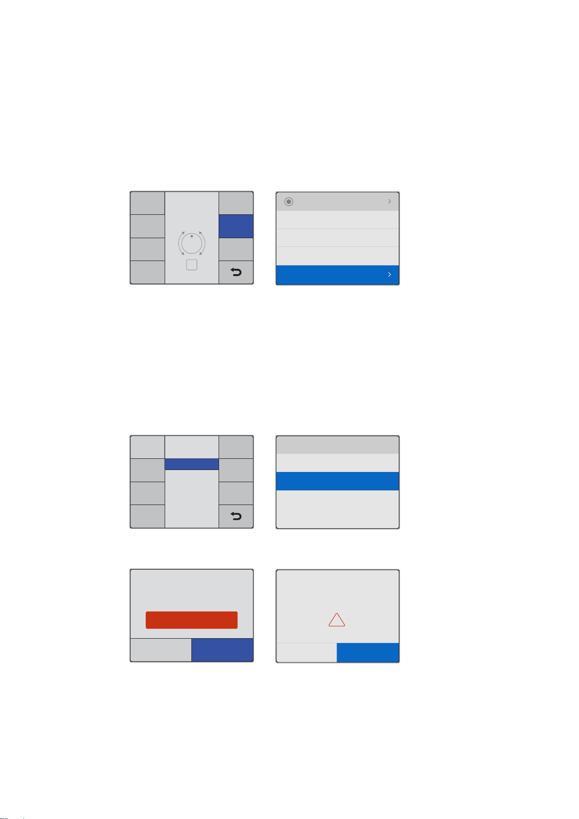
To format using your HyperDeck:
Main MenuVideo
Timecode
Setup
Format
SSD
Record
Select
Open
SET
Audio Channels
Format Card
Record Trigger
Codec
4 Channels
None
ProRes HQ
Record
Select Format
exFat
OS X Extended
Format SSD 1
exFAT
Format
SSD 1
Format
SSD 2
HFS+
Cancel
This will erase all data from your card
This action cannot be undone.
Format SD 2 to OS X Extended?
Format
!
Format SSD 1 as HFS+?
Cancel Format SSD
This action cannot be undone.
Your disk’s contents will be erased.
1 Insert the media you want to format into either of the SD card or SSD slots.
2 Press the ‘disp’ or ‘menu’ button on your HyperDeck’s control panel.
3 On HyperDecks that record on SSDs, turn the jog/shuttle wheel and press the set
button to select ‘format SSD’ on the LCD menu.
On HyperDeck Studio Mini, turn the jog/shuttle wheel and use the set button to enter
the ‘record’ menu on the LCD and select ‘format card’.
Turn the jog/shuttle wheel clockwise to select ‘format SSD’ on the LCD menu.
OnHyperDeck Studio Mini, the ‘format card’ setting is in the ‘record’ menu.
4 Select the SD card or SSD you want to format on the LCD using the jog/shuttle wheel.
Remember to press the ‘set’ button to confirm your selection.
5 Now set your desired format from the ‘HFS+’ or ‘exFAT’ options.
6 A warning message will appear on the LCD asking you to confirm the format. Make sure
you have backed up any important data before you confirm as this action cannot be
undone. Confirm the format by selecting ‘format’ for SD cards, or ‘format SSD’ using the
jog/shuttle wheel and pressing the ‘set’ button.
Set your desired format from the HFS+ or exFAT options. OnHyperDeck
Studio Mini, HFS+ is labeled ‘OS X Extended’
Confirm the format by using the jog/shuttle wheel and pressing the set button
A progress bar will show you the formatting progress. When your HyperDeck has finished
formatting, ‘formatting complete’ will display on the LCD. Press the ‘set’ button again to return
to the menu.
18About SSDs and SD Cards
Page 19
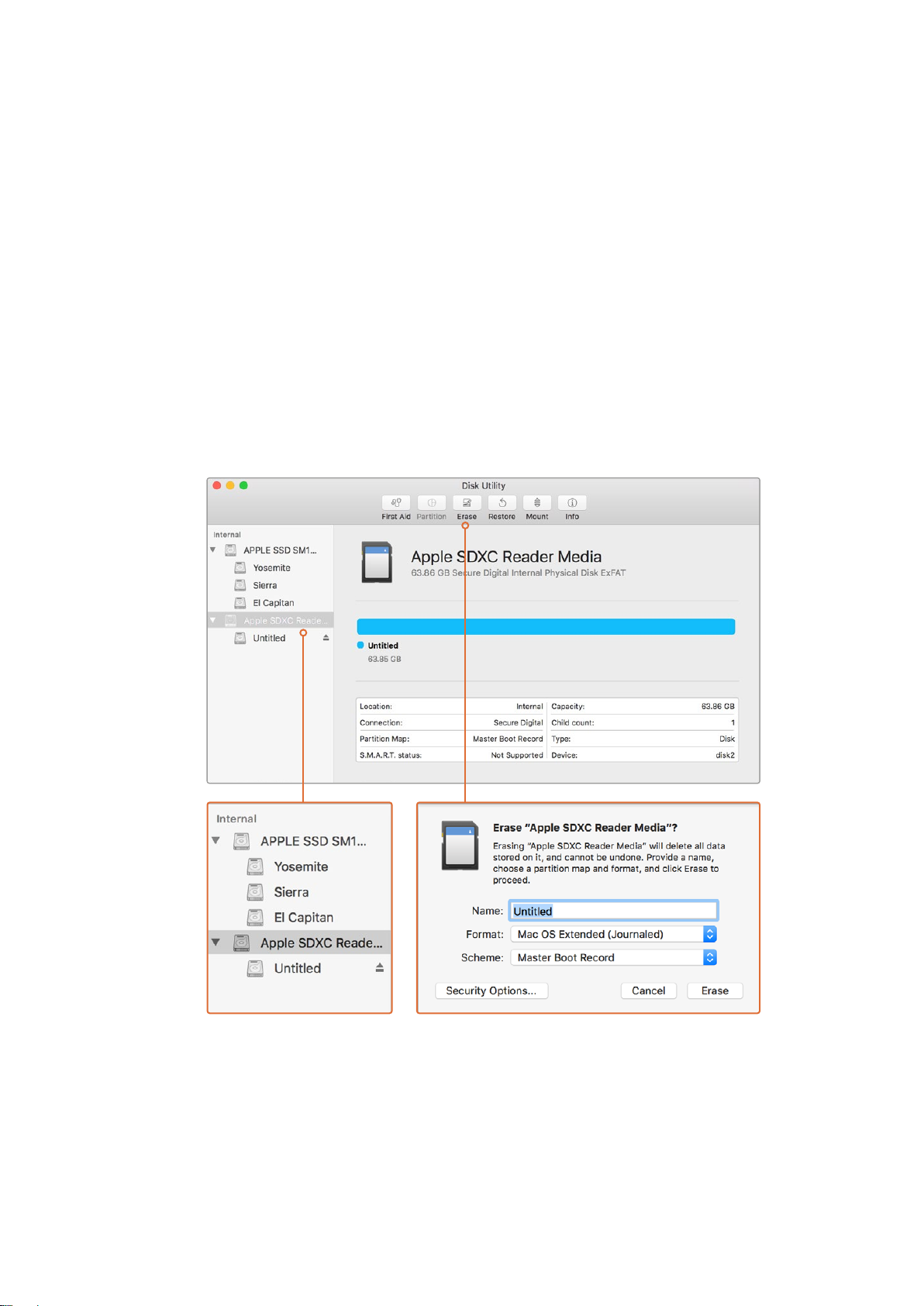
Formatting Media on a Mac OS Computer
The Disk Utility application included with Mac OS can format a drive in the HFS+ or exFAT
formats. Make sure you back up anything important from your disk as you will lose everything
on it when it is formatted.
To format on a Mac OS computer:
1 Connect an SSD to your computer with an external dock or cable adapter and dismiss
any message offering to use your SSD for Time Machine backups.
For SD cards, insert the card into your computer’s SD card slot, or connect it to your
computer via an external card reader.
2 Go to applications/utilities and launch Disk Utility.
3 Click on the disk icon of your SSD or SD card and then click the erase tab.
4 Set the format to Mac OS Extended (Journaled) or exFAT.
5 Type a name for the new volume and then click erase. Your media will quickly be
formatted and made ready for use with HyperDeck.
Use Disk Utility on Mac OS to erase your SSD or SD card
in the Mac OS Extended (Journaled) or exFAT format
19About SSDs and SD Cards
Page 20
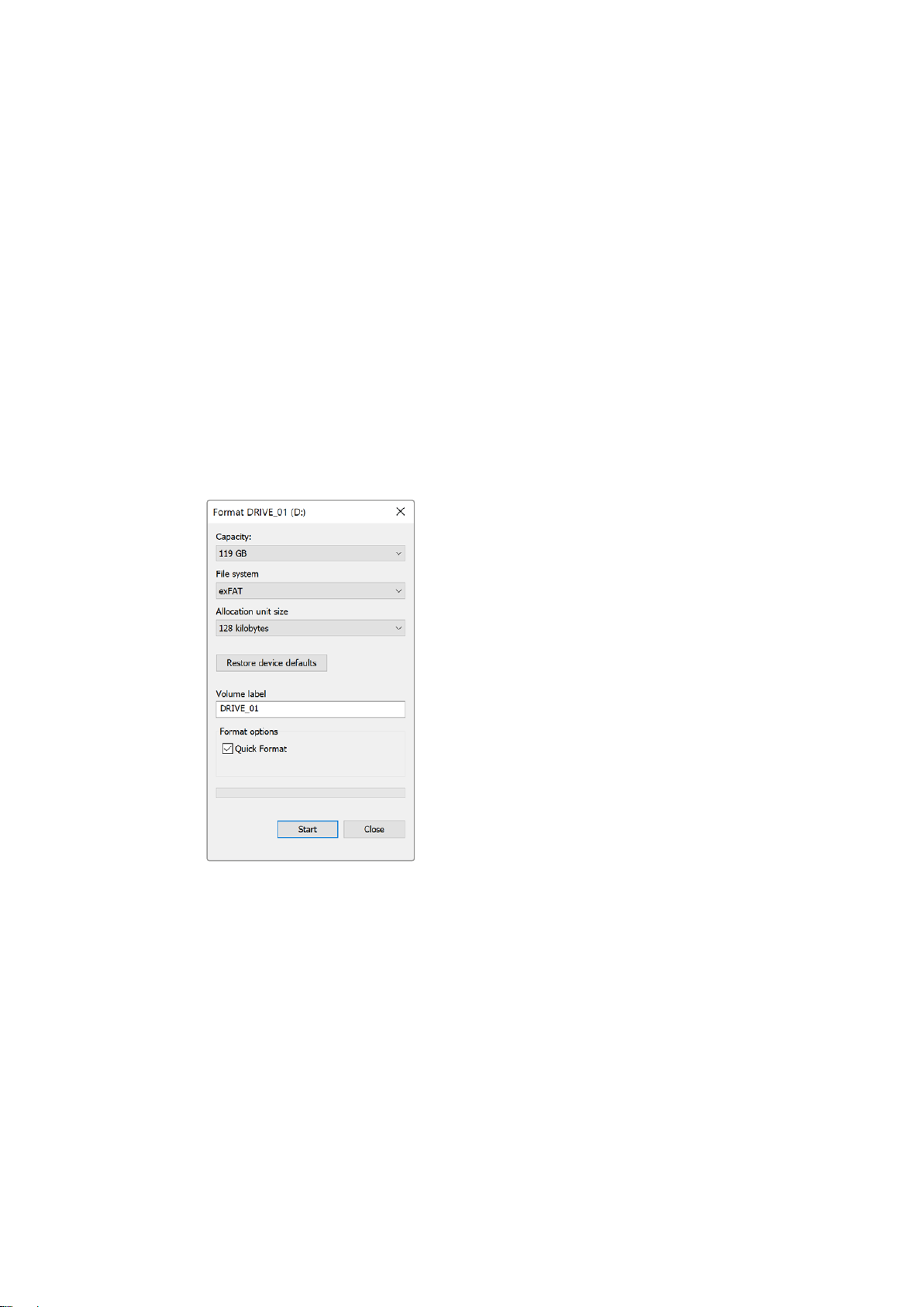
Formatting Media on a Windows computer
The format dialog box can format a drive in the exFAT format on a Windows PC. Make sure you
back up anything important from your SSD or SD card as you will lose everything on it when it
isformatted.
To format on a Windows computer:
1 Connect an SSD to your computer with an external dock or cable adapter.
For SD cards, insert the card into your computer’s SD card slot, or connect it to your
computer via an external card reader.
2 Open the start menu or start screen and choose computer. Right-click on your
SSD or SD card.
3 From the contextual menu, choose format.
4 Set the file system to exFAT and the allocation unit size to 128 kilobytes.
5 Type a volume label, select quick format and click Start.
6 Your media will quickly be formatted and made ready for use with HyperDeck.
Use the Format dialog box feature in Windows to
format your SSD or SD card in the exFAT format
20About SSDs and SD Cards
Page 21
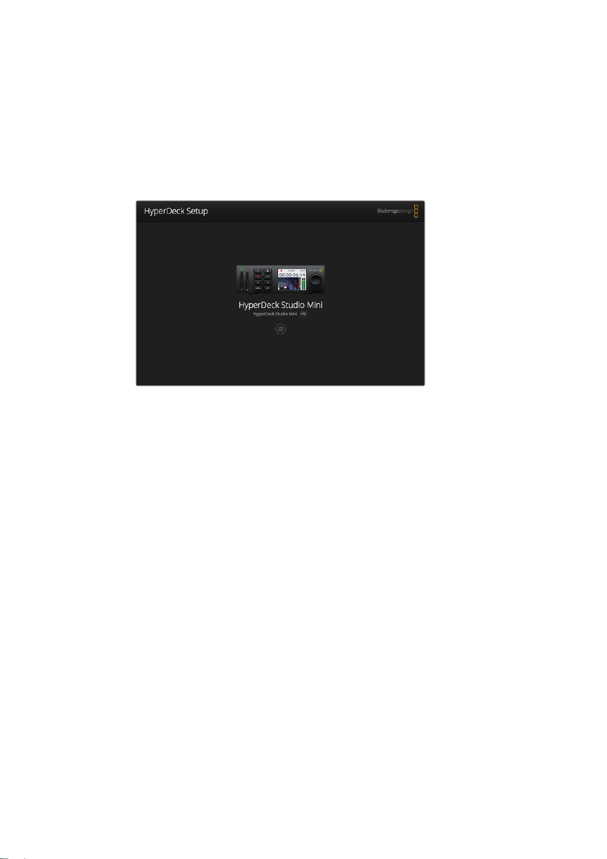
Blackmagic HyperDeck Setup
Using HyperDeck Setup
Blackmagic HyperDeck Setup is used to change settings and update the internal software in
your HyperDeck. In addition to installing HyperDeck Setup, uncompressed 10 bit codecs are
installed for Mac and Windows.
The home page of HyperDeck Setup. If you have multiple HyperDecks
connected to your computer, you can choose between them by
clicking on the arrows at the sides of the home page
How to Update Your HyperDeck Software on Mac
1 Download and unzip the HyperDeck Setup software.
2 Open the resulting disk image and launch the HyperDeck Installer.
Follow the onscreen instructions.
3 After installing, connect a USB cable from HyperDeck to your computer.
4 Launch Blackmagic HyperDeck Setup and follow any onscreen prompt to update the
internal software in your HyperDeck. If no prompt appears, the internal software is up
to date and there is nothing further you need to do.
How to Update Your HyperDeck Software on Windows
1 Download and unzip the HyperDeck Setup software.
2 You should see a HyperDeck Setup folder containing this manual and the HyperDeck
Setup utility installer. Double-click the installer and follow the onscreen prompts to
complete the installation.
3 After installing, connect a USB cable from HyperDeck to your computer.
4 Launch Blackmagic HyperDeck Setup and follow any onscreen prompt to update the
internal software in your HyperDeck. If no prompt appears, the internal software is up
to date and there is nothing further you need to do.
21Blackmagic HyperDeck Setup
Page 22
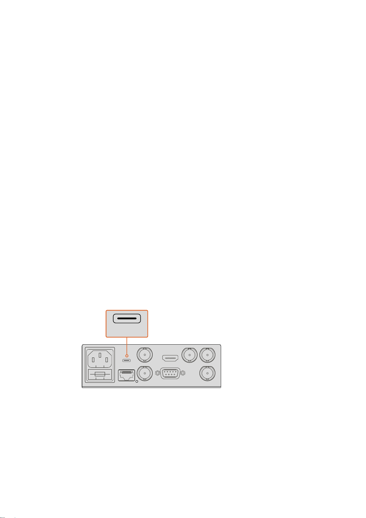
Selecting Your Video Format
REF OUT
REF INETHERNET PoE+
SDI OUT
SDI IN
HDMI OUT
REMOTE IN
BA
USB-C
REF OUT
SDI OUT
HDMI OUT
BA
USB-C
All HyperDecks record compressed HD video using Apple ProRes and Avid DNxHD 220x
codecs. HyperDeck models that record on SSDs can also record uncompressed HD video.
HyperDeck Studio Pro records Ultra HD using ProRes codecs. HyperDeck Studio Mini and
HyperDeck Studio 12G support ProRes and DNxHR HQX for Ultra HD recording.
HyperDeck Studio Mini also records HD video using the H.264 codec, providing much longer
record times with cheaper SD media, and offers a wider family of DNx codecs including
DNxHD145 and DNxHR SQ.
You can change the codec you want from the front panel LCD menu, or you can use the
HyperDeck Setup software utility depending on which you prefer. For more information on how
to change your codec using the front panel, refer to the ‘control panel display menu’ section.
HyperDecks that record on SSDs can record 10-bit uncompressed QuickTime files on a fast
SSD, or to a compressed format if you have a slower SSD or want to fit longer high definition
recordings on a single SSD. You can also change the format between recording clips, making it
possible to have uncompressed QuickTime files as well as compressed files on the same disk.
Working with uncompressed video is exciting as there is simply no better quality. However,
ifcompressed video better suits your workflow, or if you need to fit more video on a SSD,
youcan choose a high quality professional compressed video format which is also perfect
for editing.
To choose a video format using HyperDeck Setup:
1 Connect HyperDeck to your computer via USB.
2 Launch HyperDeck Setup. Your HyperDeck model will be named in the setup utility
home page.
3 Click on the circular ‘setup’ icon or the image of your HyperDeck to open the
settings page.
4 In the ‘record’ settings, click on the ‘codec’ drop down menu and select your desired
codec. Click ‘save’ to confirm your setting.
To change settings using HyperDeck Setup, plug HyperDeck
into your computer via the USB port
22Blackmagic HyperDeck Setup
Page 23
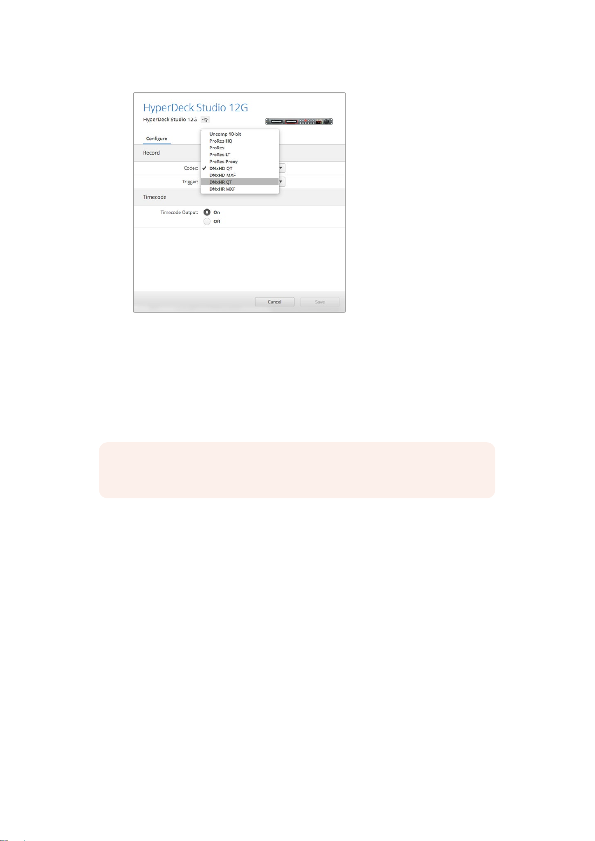
Use HyperDeck Setup to select your desired
recording and playback format
All subsequent clips will be recorded in the chosen format.
Setting the recording format also sets the playback format. For example, if you want to play
back an uncompressed 10-bit QuickTime file, set the recording format to Uncompressed 10-bit
QuickTime. Setting Avid DNxHD as the recording format lets you play DNxHD 220x QuickTime
and MXF clips, and by selecting Apple ProRes you can play clips using any of the
ProRes codecs.
NOTE Currently, HyperDeck Studio Mini will play back H.264 files recorded on a
HyperDeck Studio Mini, but not H.264 files recorded on other video equipment.
Choosing a Codec
Each codec is determined using a balance between video quality, level of compression and
resulting file size. The less compression you use the more information you will have in your files
for a range of workflows, but there are occasions where storage space requires smaller files.
For example, when recording for archival purposes, ProRes 422 Proxy, ProRes LT, DNxHD 45 or
DNxHR LB are a good choice as they provide good video quality in a smaller file size.
For short form editorial and color grading workflows, 10-bit codecs such as ProRes 422 HQ,
DNxHR HGX or DNxHD 220x are a great choice. They offer the least amount of compression
and therefore more latitude in post production, but the files sizes are larger.
ProRes 422, DNxHR SQ or DNxHD 145 work well in long form editorial workflows. These files
are smaller but still high enough quality for broadcast delivery and are widely used in post
production. HyperDeck Studio Mini can also record OP-1A DNx MXF files allowing multiple
tracks of audio to be recorded in the same interleaved file.
23Blackmagic HyperDeck Setup
Page 24
For YouTube delivery from HyperDeck Studio Mini, you have the flexibility of three H.264
options, ‘high’, ‘medium’ and ‘low’. When recording H.264, your audio compression will default
to 2 channels of AAC audio so you can simply upload your recorded files to YouTube. If you
want the benefits of smaller file size but also the flexibility of additional audio channels, you can
also record up to 16 channels of PCM audio instead. It’s worth noting that H.264 files will default
to record 2 channels of AAC audio, so if you want record PCM audio instead, after selecting
your H.264 quality, select ‘audio channels’ in the ‘record’ menu and select how many audio
channels you want.
You may decide to experiment to see which format best suits your workflow.
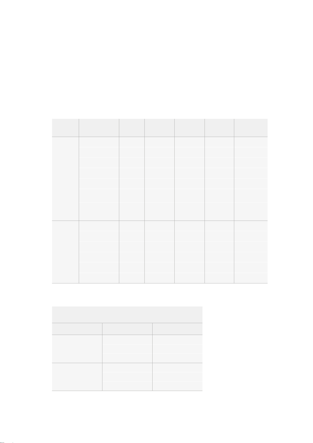
HyperDeck Disk Recorders support the following codecs.
Codecs Bit Depth
Uncompressed 10-bit Yes Yes Ye s No
ProRes 422 HQ 10-bit Yes Yes Ye s Yes
ProRes 422 10-bit Ye s Yes Yes Yes
ProRes 422 LT 10-bit Yes Yes Yes Ye s
QuickTime
QuickTime
and MXF
ProRes 422 Proxy 10-bit Yes Yes Yes Ye s
ProRes 4444 12-bit No No No
H.264 – No No No
Avid DNxHD 220x 10-bit Yes Ye s Yes Ye s
Avid DNxHD 145 8-bit No No No Yes
Avid DNxHD 45 8-bit No No No Yes
Avid DNxHR HQX 10-bit No No Yes Ye s
Avid DNxHR SQ 8-bit No No No Yes
Avid DNxHR LB 8-bit No No No Yes
HyperDeck
Studio
HyperDeck
Studio Pro
HyperDeck
Studio 12G
HyperDeck
Studio Mini
Yes
(HD playback only)
Yes
(HD recording
and playback)
MXF files recorded on the HyperDeck Studio Mini are recorded in the OP-1A operational pattern, allowing audio and
video to be recorded in a single interleaved f ile. The HyperDeck Studio Mini supports playing back OP-1A and
OP-Atom files.
H.264 on the HyperDeck Studio Mini
Video Format Bit Rate Setting Bit Rate (Mb/s)
High 70
1080p60
1080p50
Medium 46
Low 22
High 65
Medium 42
Low 20
24Blackmagic HyperDeck Setup
Page 25
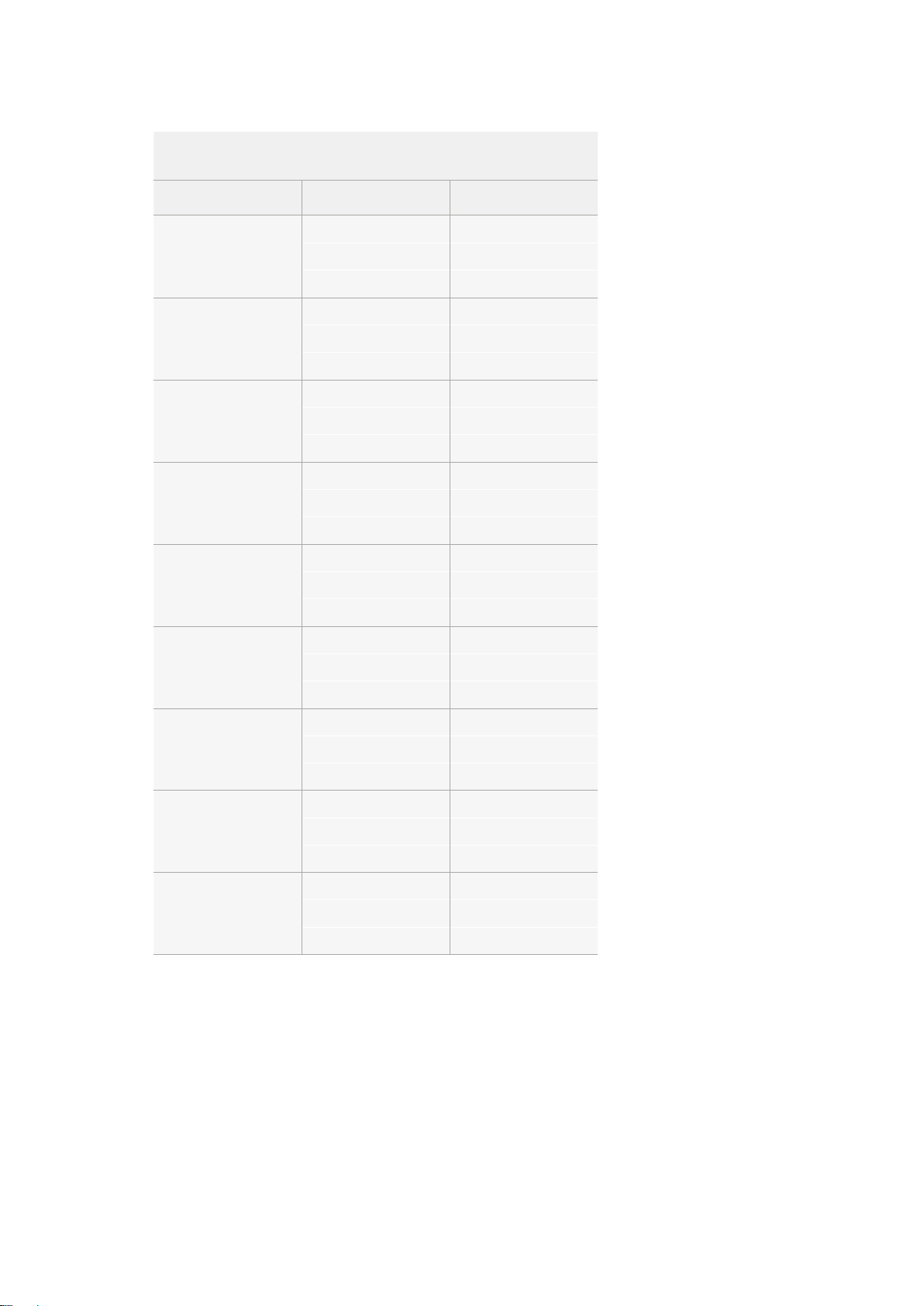
H.264 on the HyperDeck Studio Mini
Video Format Bit Rate Setting Bit Rate (Mb/s)
High 45
1080p30
1080i60
1080p25
1080i50
1080p24
720p60
Medium 29
Low 13
High 45
Medium 30
Low 15
High 40
Medium 25
Low 11
High 40.5
Medium 27
Low 14
High 38
Medium 24
Low 10.5
High 40
Medium 26
Low 12
High 33
720p50
525i59.94 NTSC
625i50 PAL
Medium 21
Low 9.5
High 10
Medium 7.5
Low 4
High 10
Medium 7
Low 4
HyperDeck Studio Mini will play back H.264 files recorded on a HyperDeck Studio Mini, but not
H.264 files recorded on other video equipment.
25Blackmagic HyperDeck Setup
Page 26
Control Panel Display Menu
CodecCodec
ProRes
ProRes LT
ProRes Proxy
Uncomp 10-bit
Record
Trigger
ProRes HQ
Codec
ProRes LT
ProRes Proxy
ProRes
ProRes HQ
Codec
ProRes HQ
ProRes
ProRes LT
ProRes Proxy
Codec
Record
Trigger
Uncomp 10-bit
Using the Display Menu
Use your HyperDeck’s control panel display menu to change your video and audio inputs and
outputs as well as any settings changes you would make in HyperDeck Setup such as trigger
recording, timecode output and your chosen recording codec.
HyperDeck Studio Mini has a list based menu, and HyperDecks that record on SSDs have a
tile based menu, so the position of some settings in the menu may appear slightly different
To change a setting in the menu:
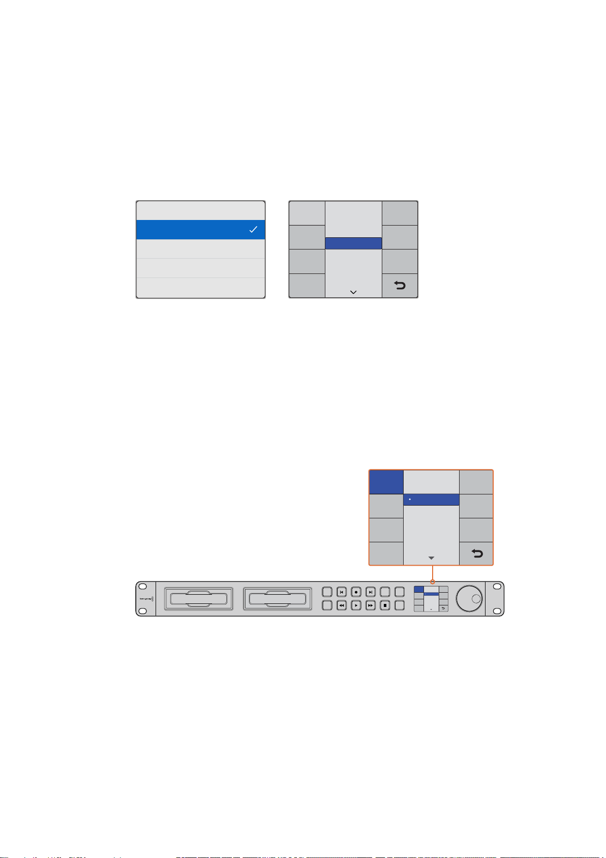
1 Press the ‘display’ or ‘menu’ button to display the main menu.
2 Use the jog/shuttle wheel on the front of HyperDeck to highlight different options.
3 Press the ‘set’ button to confirm a selection.
4 To return to a previous menu, press the ‘menu’ button on HyperDeck Studio Mini,
orscroll to the ‘return’ arrow and press ‘set.
5 Press the ‘display’ or ‘menu’ button to exit.
Codec
DISP
SET
INPUT
Codec
REM
Uncomp 10-bit
Record
Trigger
ProRes HQ
ProRes
ProRes LT
JOG
ProRes Proxy
Press the ‘display’ or ‘menu’ button to enter the LCD menu where you
can select between various codecs and change settings
Selecting Timecode Source
When recording from HD-SDI video sources that provide embedded SMPTE RP 188 metadata,
you can record the embedded timecode from the video source instead of using timecode
generated by your HyperDeck.
26Control Panel Display Menu
Page 27

To set this using the display menu:
1 Press the ‘display’ or ‘menu’ button to display the main menu.
2 Scroll to the ‘timecode’ menu and press ‘set’.
3 Press ‘set’ to enter the ‘timecode input’ menu and select ‘input’.
4 Press ‘set’ to confirm your selection.
It might be necessary to turn on the RP 188 setting in your camera before HyperDeck will be
able to record the timecode.
HyperDeck Studio Mini features a timecode output option so you can select to output either
thetimeline timecode or clip timecode.
To set the timecode output to clip timecode:
1 Press the ‘menu’ button to display the main menu.
2 Scroll to the ‘timecode’ menu and press ‘set’.
3 Scroll to ‘timecode output’ and press ‘set’.
4 Scroll to ‘clip’ and press ‘set’ to confirm your selection.
Press ‘menu’ to return to the main view.
Trigger Recording
HyperDeck supports trigger recording which means you can set to auto record on your
HyperDeck using either start/stop or timecode run recording. When using trigger recording
you will need to turn on the ‘remote’ option of your HyperDeck. On HyperDeck Studio Mini you
can turn on remote by pressing the ‘menu’ button to open the LCD menu, navigate to ‘settings’
and set remote to ‘on’. On other HyperDeck models, turn on the remote feature by pressing the
‘rem’ button found on the front of the panel. The button will illuminate to let you know remote
is enabled.
SDI Start/Stop Recording
HyperDeck supports start/stop recording, which means when you press the record button on
an HD-SDI camera, HyperDeck will start recording without also having to press the record
button on your HyperDeck disk recorder.
NOTE You will need a camera that can trigger the record function of HyperDeck via
HD-SDI. Cameras which support trigger recording via HD-SDI may include menu
options such as ‘trigger rec’, ‘HD-SDI remote I/F’ or ‘SDI remote start/stop trigger’.
To set start/stop trigger recording using the display menu:
Press the ‘disp’ or ‘menu’ button to display the main menu.
1 Scroll to the ‘record’ menu and press ‘set’.
2 Scroll to the ‘record trigger’ menu and press ‘set’.
3 Select ‘SDI start/stop’ and press ‘set’ to confirm your selection.
Press ‘disp/menu’ to exit.
27Control Panel Display Menu
Page 28
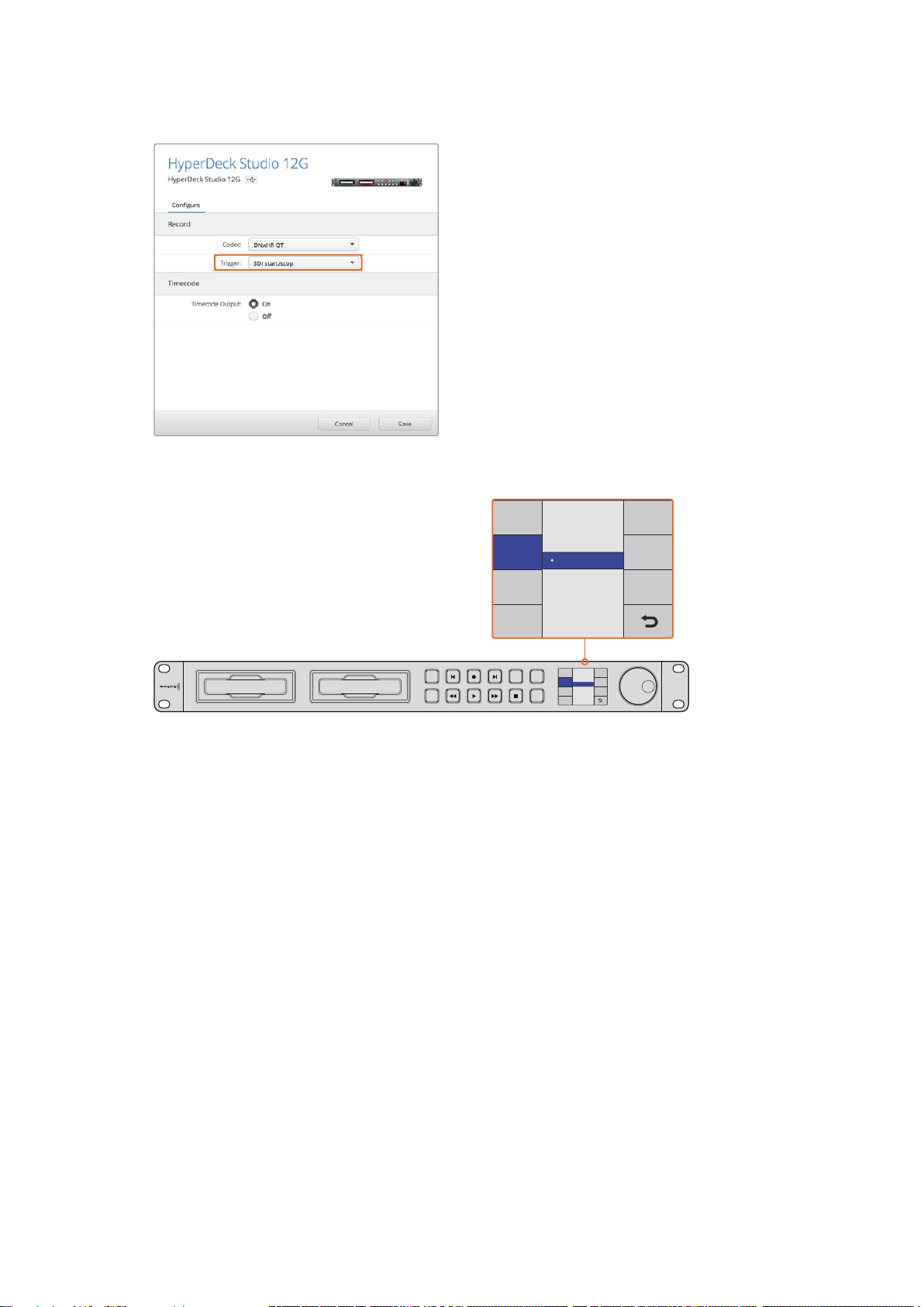
You can use the control panel LCD menu on HyperDeck,
Record Trigger
Timecode Run
Codec
Record
Trigger
None
SDI Start/Stop
or use HyperDeck Setup to enable Start/Stop recording
Record Trigger
DISP
SET
INPUT
Codec
REM
None
Record
Trigger
SDI Start/Stop
Timecode Run
JOG
The ‘record trigger’ settings let you set your HyperDeck to start and stop
recording triggered by data received over an HD-SDI connection
Timecode Run Recording
HyperDeck also supports timecode run recording, which is similar to start/stop recording, but is
only used if your HD-SDI camera does not support trigger recording via HD-SDI.
To set up timecode run recording using HyperDeck Setup:
1 Go into your camera’s timecode settings and change them from ‘free run timecode’ to
‘record run timecode’.
2 In HyperDeck Setup, set trigger recording to ‘timecode run’.
3 Remote must also be enabled via HyperDeck’s front panel or via the control panel
display menu on HyperDeck Studio Mini.
To set up timecode run recording on HyperDeck’s control panel display menu:
1 Press the ‘disp’ or ‘menu’ button to display the main menu.
2 Scroll to the ‘record’ menu and press ‘set’.
3 Scroll to the ‘record trigger’ menu and press ‘set’.
4 Select ‘timecode run’ and press ‘set’ to confirm your selection. Press ‘disp’ or
‘menu’ to exit.
28Control Panel Display Menu
Page 29
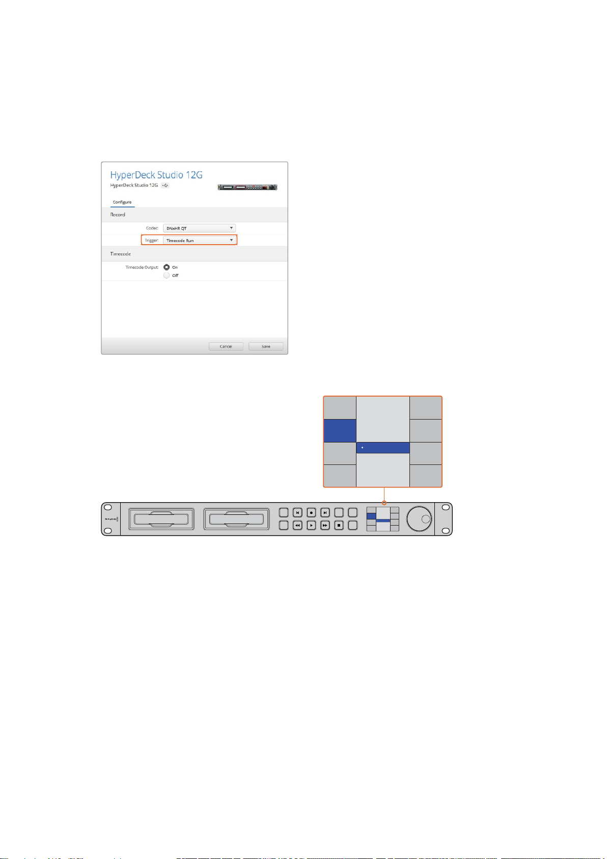
Now whenever your HyperDeck detects the timecode running via HD-SDI it will start recording.
Record Trigger
SDI Start/Stop
Codec
Record
Trigger
None
Timecode Run
Recording will stop whenever the timecode stops.
Be careful if your HyperDeck is connected to the SDI output of a video router, as any change to
the video source might cause HyperDeck to start recording unexpectedly due to a change in
timecode being detected via HD-SDI.
You can use the control panel LCD menu, or use
HyperDeck Setup to enable timecode run recording
Record Trigger
DISP
SET
INPUT
Codec
REM
None
Record
Trigger
SDI Start/Stop
Timecode Run
JOG
The ‘timecode run’ recording feature lets you trigger your HyperDeck to record whenever running
timecode is detected via the HD-SDI connection. Recording will stop when the timecode stops.
RS-422 Control
What is RS-422 Control?
The RS-422 standard is a serial deck control broadcast standard and has been used by
broadcasters since the early 1980s and is found on many decks, linear editors, non linear
editors and broadcast automation products. All current HyperDeck models support this
standard so can be integrated into broadcast automation, remote control systems, editing
systems and any kind of custom control you might like to design yourself.
HyperDeck Studio Mini also supports file based commands from the Advanced Media Protocol
via RS-422. This lets you control your HyperDeck with an external device using AMP commands
such as adding clips to a playlist, determining the filename of the next clip, looping a single clip
or timeline, or clearing a playlist.
29RS-422 Control
Page 30
Using an External RS-422 Controller
MENU
INPUT
DISP
SET
REM
JOG
REMOTE ETHERNET SD/HD/3GHD-SDI HDMI
IN OUT
REF INMON OUTOUT 2OUT 1LOOP OUTIN
MENU
INPUT
DISP
SET
01:42:56:12
SSD
2
REM
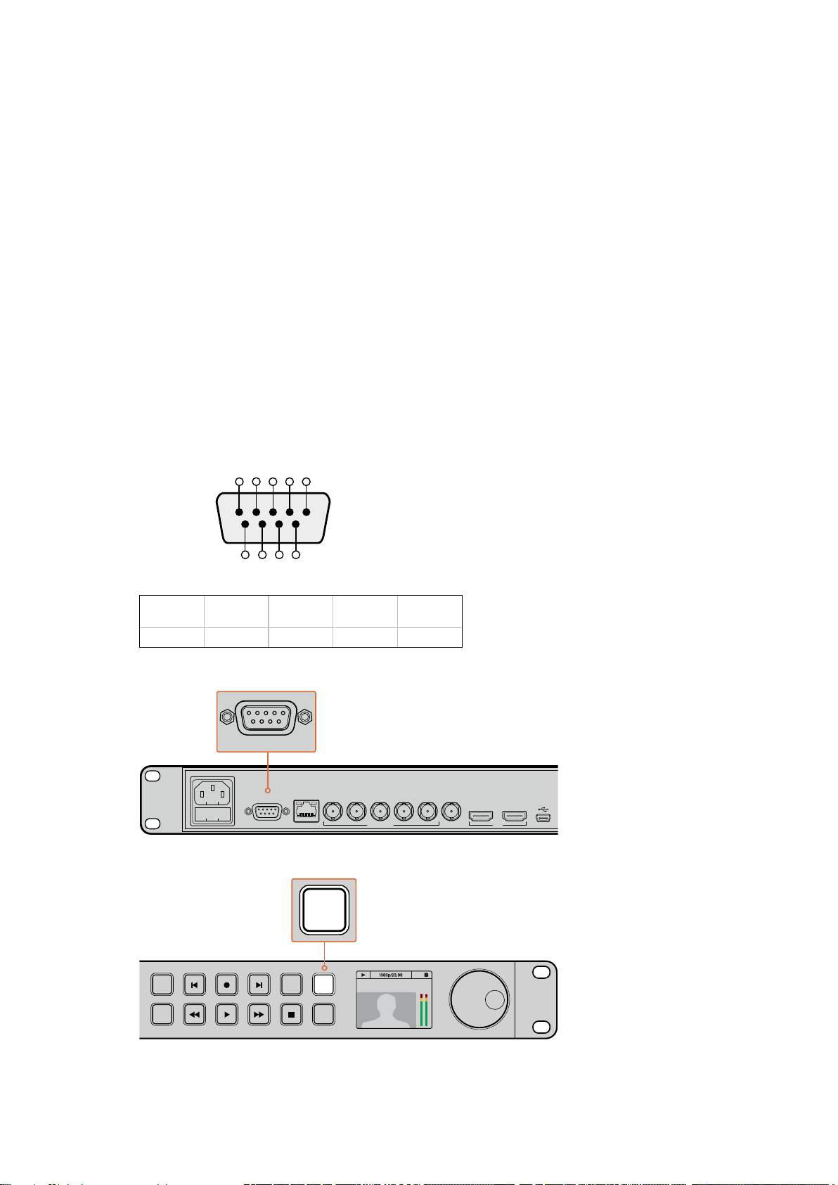
All current HyperDeck models feature an industry standard Sony™ compatible RS-422 deck
control port, which has the correct pin connections for a direct connection to any remote
controller with RS-422.
You can use pre-manufactured 9 pin cables as long as each end of the cable is wired ‘pin for
pin’ where the same pin numbers on each end of the cable are connected together. If you
would like to make custom cables, please refer to the accompanying wiring diagram.
You can remotely control your HyperDeck from an RS-422 controller instead of locally
pushing buttons.
1 Connect a video signal to your HyperDeck’s video input.
2 Connect an RS-422 cable from your external controller to your HyperDeck.
3 Enable remote control by pressing the remote button on the front control panel, or via
the LCD menu in HyperDeck Studio Mini, to allow remote deck control.
You can now remotely start and stop recording and playback of your HyperDeck as well as
performing other common jog and shuttle functions. The full list of supported RS-422
commands is in the following section named ‘supported RS-422 commands’.
5 4 3 2 1
9 8 7 6
Receive
(–)
Receive
(+)
2 7 8 3 1, 4, 6, 9
RS-422 remote pin connections
Transmit
(–)
Transmit
(+)
Ground
Pins
REF INMON OUTOUT 2OUT 1LOOP OUTIN
IN OUT
REMOTE ETHERNET SD/HD/3GHD-SDI HDMI
Remote port on HyperDeck Studio and HyperDeck Studio 12G
2
INPUT
DISP
SET
Make sure your HyperDeck has remote set to ‘on’ in the LCD menu,
or via the control panel remote button, to enable RS-422 deck control
REM
JOG
01:42:56:12
SSD
30RS-422 Control
Page 31

Supported RS-422 Commands
Command Reply No Remote Notes
0 - System Control
0x00 0x11 DeviceTypeRequest
1 - Slave Response
0x20 0x00 Stop Acknowledge Disabled
0x20 0x01 Play Acknowledge Disabled
0x20 0x02 Record Acknowledge Disabled
0x20 0x04 StandbyOff Acknowledge Disabled
0x20 0x05 StandbyOn Acknowledge Disabled
0x20 0x0F Eject Acknowledge Disabled
0x20 0x10 FastFwd Acknowledge Disabled
0x21 0x11 JogFwd1 Acknowledge Disabled
0x22 0x11 JogFwd2 Acknowledge Disabled
0x21 0x12 VarFwd1 Acknowledge Disabled Uses ShuttleFwd1
0x22 0x12 VarFwd2 Acknowledge Disabled
0x21 0x13 ShuttleFwd1 Acknowledge Disabled
0x22 0x13 ShuttleFwd2 Acknowledge Disabled
0x20 0x20 Rewind Acknowledge Disabled
0x21 0x21 JogRev1 Acknowledge Disabled
0x22 0x21 JogRev2 Acknowledge Disabled
0x21 0x22 VarRev1 Acknowledge Disabled Uses ShuttleRev1
0x22 0x22 VarRev2 Acknowledge Disabled
0x21 0x23 ShuttleRev1 Acknowledge Disabled
0x22 0x23 ShuttleRev2 Acknowledge Disabled
0x20 0x30 Preroll Acknowledge Disabled
0x24 0x31 CueData Acknowledge Disabled
0x20 0x34 SyncPlay Acknowledge Disabled
0x21 0x38 ProgSpeedPlayPlus Acknowledge Disabled
0x21 0x39 ProgSpeedPlayMinus Acknowledge Disabled
0x20 0x40 Preview Acknowledge Disabled Status bits are set
0x20 0x41 Review Acknowledge Disabled Status bits are set
0x20 0x43 OutpointPreview Acknowledge Disabled
0x22 0x5C DMCSetFwd Acknowledge Disabled
0x22 0x5D DMCSetRev Acknowledge Disabled
0x20 0x60 FullEEOff Acknowledge Disabled
NTSC: 0xF0E0
PAL: 0xF1E0
24P: 0xF2E0
Enabled
Treated as N=1;
Same as JogFwd1
Treated as N=1;
Same as VarFwd1
Treated as N=1;
Same as ShuttleFwd1
Treated as N=1;
Same as JogRev1
Treated as N=1;
Same as VarRev1
Treated as N=1;
Same as ShuttleRev1
31RS-422 Control
Page 32

Command Reply No Remote Notes
0x20 0x61 FullEEOn Acknowledge Disabled
0x20 0x63 SelectEEOn Acknowledge Disabled
4 - Preset/Select Control
0x40 0x10 InEntry Acknowledge Disabled
0x22 0x23 ShuttleRev2 Acknowledge Disabled
0x20 0x30 Preroll Acknowledge Disabled
0x24 0x31 CueData Acknowledge Disabled
0x20 0x34 SyncPlay Acknowledge Disabled
0x21 0x38 ProgSpeedPlayPlus Acknowledge Disabled
0x21 0x39 ProgSpeedPlayMinus Acknowledge Disabled
0x40 0x11 OutEntry Acknowledge Disabled
0x44 0x14 InDataPreset Acknowledge Disabled
0x44 0x15 OutDataPreset Acknowledge Disabled
0x40 0x18 InShift+ Acknowledge Disabled
0x40 0x19 InShift- Acknowledge Disabled
0x40 0x1A OutShift+ Acknowledge Disabled
0x40 0x1B OutShift- Acknowledge Disabled
0x40 0x20 InReset Acknowledge Disabled
0x40 0x21 OutReset Acknowledge Disabled
0x40 0x22 AInReset Acknowledge Disabled
0x40 0x23 AOutReset Acknowledge Disabled
0x44 0x31 PrerollPreset Acknowledge Disabled
0x40 0x40 AutoModeOff Acknowledge Disabled
0x40 0x41 AutoModeOn Acknowledge Disabled
0x41 0x37 InputCheck Acknowledge Disabled
6 - Sense Request
0x61 0x0A TimeCodeGenSense — —
0x61 0x0C CurrentTimeSense — —
0x60 0x10 InDataSense InData Enabled
0x60 0x11 OutDataSense OutData Enabled
0x60 0x12 AInDataSense AInData Enabled
0x60 0x13 AOutDataSense AOutData Enabled
0x61 0x20 StatusSense StatusData Enabled
0x60 0x2B RemainTimeSense RemainTimeData Enabled
0x60 0x2E SpeedSense SpeedData Enabled
0x60 0x31 PrerollTimeSense PreRollTimeData Enabled
0x60 0x36 TimerModeSense TimerModeData Enabled
0x60 0x3E RecordInhibitSense RecordInhibitStatus Enabled
7 - Sense Reply
Treated as N=1;
Same as ShuttleRev1
ignored, Status bit
remembered
ignored, Status bit
remembered
32RS-422 Control
Page 33

Command Reply No Remote Notes
0x78 0x00 Timer1Data — —
0x78 0x04 LTCUserBitsTimeData — —
0x78 0x06 VITCUserBitsTimeData — —
0x74 0x06 VITCTimeData — — Current Time
0x74 0x07 UserBitsVITCTimeData — — 00:00:00:00
0x74 0x08 GenTCData — — Current Time
0x78 0x08 GenTCUBData — —
0x74 0x09 GenUBData — — 00:00:00:00
0x74 0x10 InData — —
0x74 0x11 OutData — —
0x74 0x12 AInData — —
0x74 0x13 AOutData — —
0x74 0x14 CorrectedLTCTimeData — — Current Time
0x70 0x20 StatusData — —
0x76 0x2B RemainTimeData — —
0x71 0x2E SpeedData — —
0x74 0x31 PrerollTimeData — —
0x71 0x36 TimerModeData — — Returns 0 (TimeCode)
0x72 0x3E RecordInhibitStatus — —
Current Time and
00:00:00:00
Current Time and
00:00:00:00
Current Time and
00:00:00:00
Current Time and
00:00:00:00
Please see “Status Bits”
sheet: Limited to 9 bytes
of status, silently
truncated
A - Advanced Media Protocol
0xA1 0x01 AutoSkip Acknowledge Disabled
0xAX 0x15 ListNextID IDListing Enabled
0x20 0x29 ClearPlaylist Acknowledge Disabled
0x41 0x42 SetPlaybackLoop Acknowledge Disabled
0x41 0x44 SetStopMode Acknowledge Disabled
8-bit signed number of
clips to skip from current
clip
when x = 0 single clip
request when x = 1, #
clips can be specified in
the send data
Bit 0 loop mode enable,
0=false 1=true
Bit 1 is single clip/timeline
0=single clip
1=timeline
0 = Off
1 = Freeze on last frame
2 = Freeze on next clip
3 = Show black
33RS-422 Control
Page 34
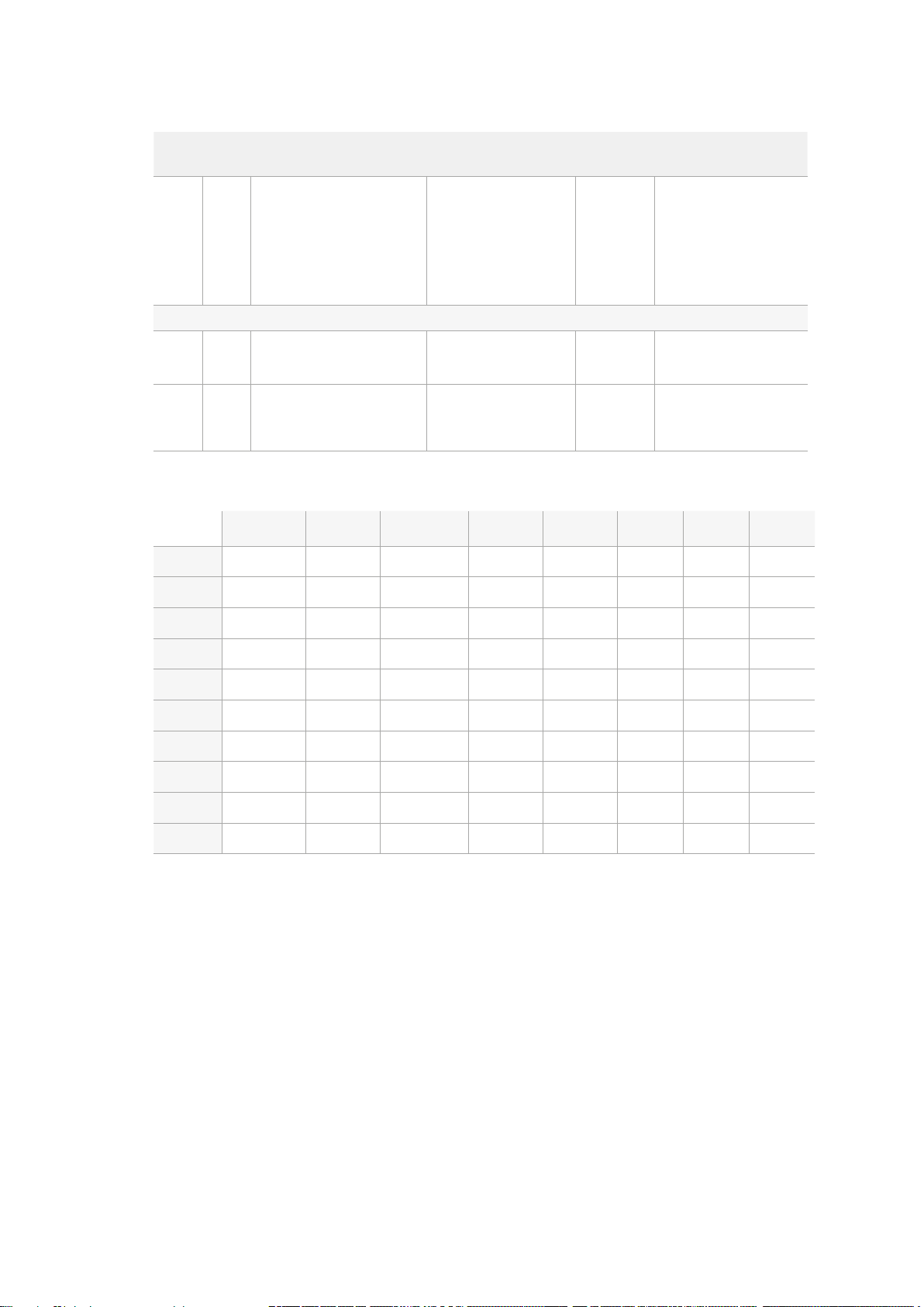
Command Reply No Remote Notes
0x4f 0x16 AppendPreset Acknowledge Disabled
Blackmagic Extensions
0x08 0x02 BmdSeekToTimelinePosition Acknowledge Disabled
0x81 0x03 BMDSeekRelativeClip Acknowledge Disabled
RS-422 Developer Information
bit 7 bit 6 bit 5 bit 4 bit 3 bit 2 bit 1 bit 0
2 Bytes for the length N
of the clip name
N Bytes for each character
of the clip name
4 Byte in point timecode
(format is FFSSMMHH)
4 Byte out point timecode
(format is FFSSMMHH)
16-bit little endian
fractional position
[0..65535]
One-byte signed integer,
which is the number of
clips to skip (negative for
backwards).
Byte 0
Byte 1
Byte 2
Byte 3
Byte 4
Byte 5
Byte 6
Byte 7
Byte 8
Byte 9
0 0 Cassette out 0 0 0 0 Local
Standby 0 Stop 0 Rewind Forward Record Play
Servo Lock 0 Shuttle Jog Var Direction Still 1
Auto Mode 0 0 0 Aout Set Ain Set Out Set In Set
Select EE Full EE 0 0 0 0 0 0
0 0 0 0 0 0 0 0
0 Lamp Still Lamp Fwd Lamp Rev 0 0 0 0
0 0 0 0 0 0 0 0
0 0 Near EOT EOT 0 0 0 0
0 0 0 0 0 0 0 0
34RS-422 Control
Page 35

Variables
Cassette Out
Local
Standby
Direction
Still
Auto Mode
Select EE, Full EE
Lamp Still/Fwd/Rev
Near EOT
EOT
Others
Cue Complete (byte 2, bit 0)
HyperDeck Serial RS-422 Protocol
Protocol
Set if no SSD is present
Set if Remote is disabled (local control)
Set if a disk is available
Clear if playback is forwarding, set if playback is reversing
Set if playback is paused, or if in input preview mode
Set if in Auto Mode
Set if in input preview mode
Set according to playback speed and direction
Set if total space left on available SSDs is less than 3 minutes
Set if total space left on available SSDs is less than 30 seconds
Always 1: Cue requests are always instantaneous
Based on Sony 9-pin protocol
Interface
Baud rate 38.4 Kbps
1 start bit
8 data bits
1 stop bit
1 parity bit
Odd parity
Transferring Files over a Network
With Blackmagic HyperDeck Studio Mini, you can access files on your disk recorder over a
network using file transfer protocol, or ‘ftp’. This means that you don’t have to remove SD cards
from your HyperDeck Studio Mini to transfer files to and from the recorder.
Connecting to HyperDeck Studio Mini
With your computer and HyperDeck Studio Mini on the same network, all you’ll need is an
ftpclient and your HyperDeck Studio Mini’s IP address.
1 Download and install an FTP client on the computer you want to connect
your HyperDeck to. Werecommend Cyberduck, FileZilla or Transmit but most
FTPapplications will work. Cyberduck and FileZilla are free downloads.
2 Connect your HyperDeck Studio Mini to your network using an Ethernet cable and
noteits IP address. To access the IP address, press the ‘menu’ button and rotate the
‘jog/shuttle’ wheel to access the ‘network’ screen. You’ll see your HyperDeck Studio
Mini’s IP address at the bottom of this screen.
35Transferring Files over a Network
Page 36
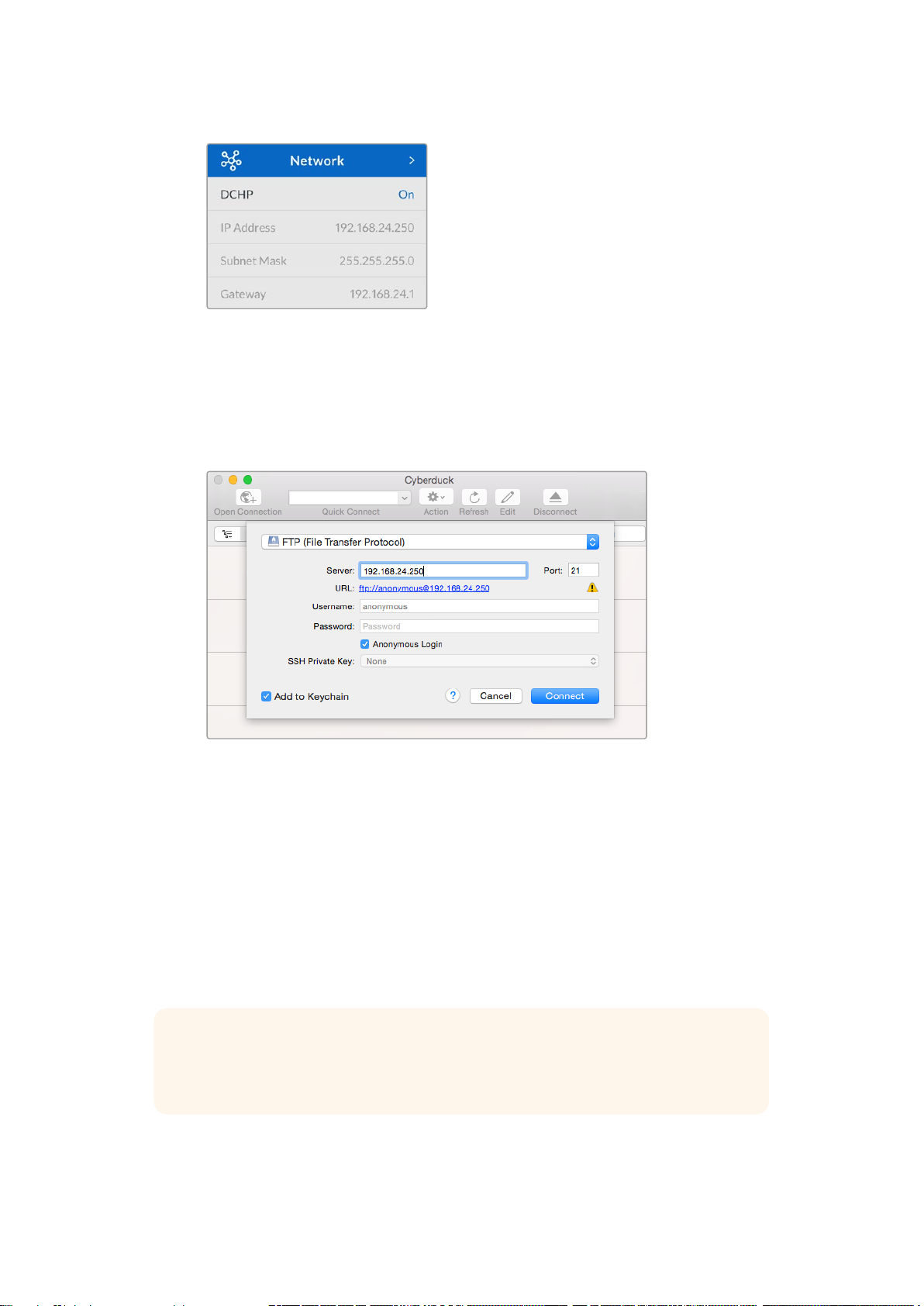
You can find your HyperDeck Studio Mini’s
IPaddress in the smart panel’s ‘network’ screen
3 Enter your HyperDeck Studio Mini’s IP address into your TCP application’s connection
dialog. The naming and position of this box can vary between applications, but it is
usually labeled ‘server’ or ‘host.’ If your FTP program includes an ‘anonymous login’
checkbox, make sure this is checked.
When connecting to HyperDeck Studio Mini, you don’t need to enter a username or
password. Simply enter your disk recorder’s IP address in your FTP application’s ‘server’
or ‘host’ field and check an ‘anonymous login’ checkbox if one is available.
Transferring Files
Once connected to HyperDeck Studio Mini you can transfer files as you normally would with
your ftp program. Most ftp applications have a drag and drop interface, but check your
particular application for the appropriate method.
You can transfer any file to and from your HyperDeck Studio Mini, but it’s worth noting that any
files you intend to play back from HyperDeck Studio Mini will need to conform to your
HyperDeck’s supported codecs and resolutions. You can find a list of supported codecs in the
‘Blackmagic HyperDeck Setup’ section of this manual.
TIP You can transfer files over a network while your HyperDeck Studio Mini is
recording. HyperDeck Studio Mini will automatically adjust transfer speeds to make
sure recording is not affected.
36Transferring Files over a Network
Page 37
Connecting to an ATEM Switcher
1 7 13 19 COL 1 BARS AUX 1
2 8 14 20 COL 2
SPR
SRC
AUX 2
3 9 15
KEY
MASK
CLEAN
FEED 1
ME 2
PVW
AUX 3
4 10 16 BLK
CLEAN
FEED 2
ME 2
PGM
AUX 4
5 11 17 MP 1 MP 1K
ME 1
PVW
AUX 5
6 12 18 MP 2 MP 2K
ME 1
PGM
AUX 6
PUSHPUSHPUSHPUSH
1 7 13 19 COL 1 BARS AUX 1
2 8 14 20 COL 2
SPR
SRC
AUX 2
3 9 15
KEY
MASK
CLEAN
FEED 1
ME 2
PVW
AUX 3
4 10 16 BLK
CLEAN
FEED 2
ME 2
PGM
AUX 4
5 11 17 MP 1 MP 1K
ME 1
PVW
AUX 5
6 12 18 MP 2 MP 2K
ME 1
PGM
AUX 6
If you’re using an ATEM switcher, you can plug in up to 4 Blackmagic HyperDeck disk recorders
and control them using the ATEM software control panel. This is a very powerful feature that
effectively gives you an entire videotape department at your fingertips. You can also trigger
recording on your HyperDeck from an ATEM switcher, which is a great way of making an archive
copy of a live broadcast, or capturing B roll when live switching a production that will be fine
tuned later.
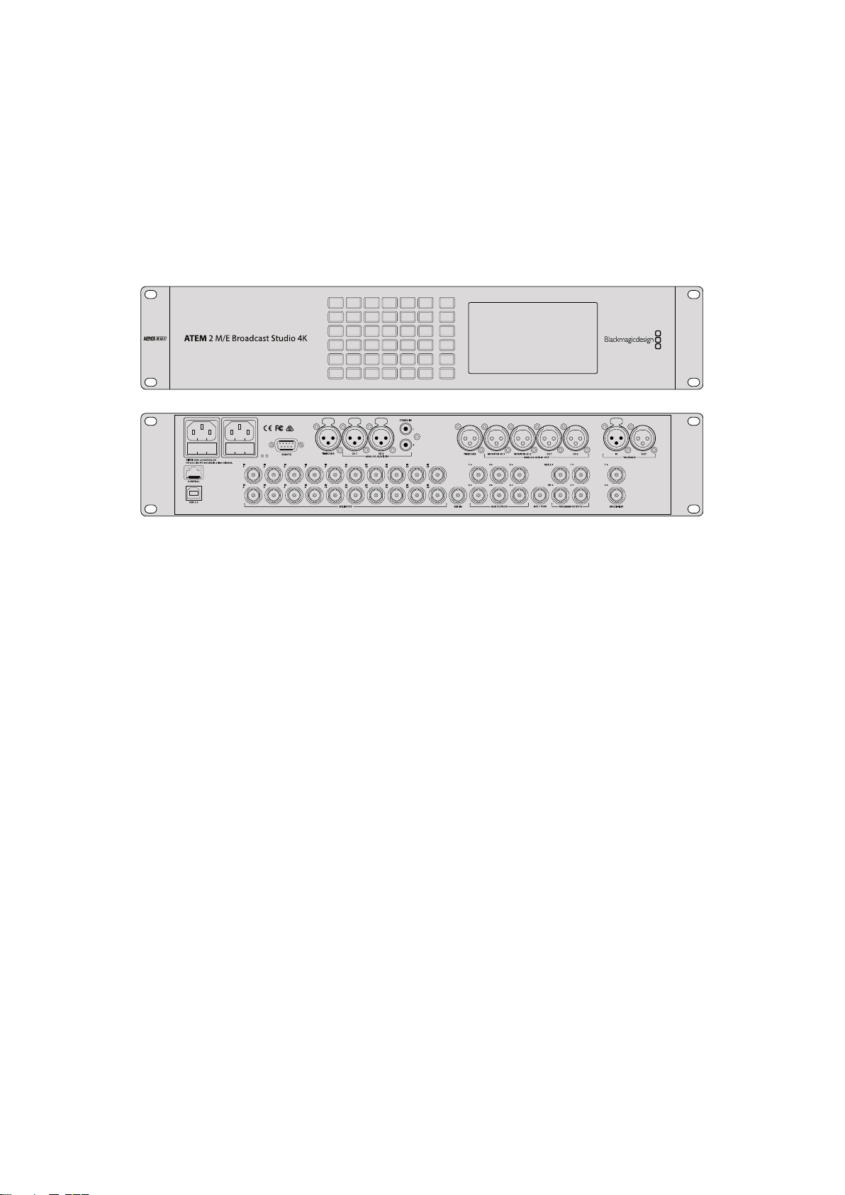
ATEM switchers, such as the ATEM 2 M/E Broadcast Studio 4K,
canconnect with up to four HyperDeck disk recorders
To connect HyperDecks to an ATEM switcher:
1 Update your ATEM Switcher to software version 6.8 or higher. This process outlined in
the ATEM Switcher manual and can even be done over Ethernet.
2 Update your HyperDeck’s internal software to version 4.3 or later. Updating your
HyperDeck software is explained earlier in this manual.
3 Connect your HyperDeck to the same network as your ATEM Switcher and note its
IP address.
Your HyperDeck’s IP address can be found via its front panel and LCD menu by
entering the ‘setup’, then ‘Ethernet’ menus from the main menu.
Alternatively, you can access your HyperDeck’s IP address on your Mac or PC via the
‘configure’ tab in BlackMagic HyperDeck Setup utility.
4 Connect one of your HyperDeck’s SDI or HDMI outputs to an SDI or HDMI source input
on your ATEM Switcher.
5 If you want to use your ATEM Switcher to trigger recording on your HyperDeck,
you’llalso need to connect a video source to your HyperDeck.
Simply connect an SDI or HDMI source to your HyperDeck as usual. To record your
ATEM switcher’s program output, connect one of your switcher’s auxilary SDI outputs to
your HyperDeck’s SDI input.
6 Enable remote by pressing the remote button on HyperDeck’s front panel, or via the
LCD menu on HyperDeck Studio Mini, to allow remote control from the switcher.
7 Complete the connection process by entering your HyperDeck’s source and
IPaddress information into your ATEM software or ATEM broadcast panel. This is very
straightforward and laid out in your ATEM switcher manual.
37Connecting to an ATEM Switcher
Page 38
2
01:42:56:12
SSD
2
REM
INPUT
DISP
REM
01:42:56:12
SSD
SET
Make sure your HyperDeck has remote set to ‘on’ in the LCD menu, or via the control
panel remote button, to enable Ethernet control with an ATEM switcher
JOG
Understanding Post
Production Workflows
Accessing Your Clips
To access your clips, simply plug the SD card or SSD into your computer via an SD card slot,
external reader, or SSD dock. You can either drag the files from the SSD or SD card directly to a
local hard drive, or you can work directly from the SSD or SD card. You can also connect SSDs
to your computer with a 2.5” eSATA to USB cable adapter, however this won’t be fast enough to
handle working directly from the SSD and is really only recommended as a portable solution for
getting your video files off the SSD and onto a laptop.
Mac OS
QuickTime is built into Mac OS. Apple ProRes, Avid DNxHD and DNxHR, and uncompressed
QuickTime movies recorded by HyperDeck can be opened in almost any video software
on Mac OS.
DNxHD and DNxHR MXF files recorded by HyperDeck can be opened with Avid Media
Composer and DaVinci Resolve for Mac. DNxHD codecs can be downloaded free from
http://www.avid.com/products/avid-dnxhr-and-dnxhd
MCC closed caption data files recorded by HyperDeck can be opened with MacCaption
software for Mac OS from http://www.telestream.net/captioning/overview.htm
Windows
Apple ProRes and uncompressed QuickTime movies recorded by HyperDeck require
QuickTime to be installed on your PC. Almost any video software on Windows that supports
QuickTime can open movies recorded by HyperDeck. QuickTime for Windows can be
downloaded free from http://www.apple.com/quicktime/download/.
DNxHD and DNxHR MXF files recorded by HyperDeck can be opened with Avid Media
Composer and DaVinci Resolve for Windows. DNxHD codecs can be downloaded free from
http://www.avid.com/products/avid-dnxhr-and-dnxhd
MCC closed caption data files recorded by HyperDeck can be opened with CaptionMaker
software for Windows from http://www.telestream.net/captioning/overview.htm
38Understanding Post Production Workflows
Page 39
Using DaVinci Resolve
Recording clips with your HyperDeck Disk Recorder is only part of the process of creating film
and television content, and just as important is the process of media backup and management
as well as editing, color correction and encoding final master files. DaVinci Resolve for Mac OS
and Windows can be downloaded free from the Blackmagic Design website so you can have a
complete solution for recording and post production!
NOTE We recommend using the latest version of DaVinci Resolve for accurate
treatment of clips recorded with your Blackmagic HyperDeck Disk Recorder.
Forexample, version 16 or later will ensure accurate color.
After connecting your SSD or SD card to your computer, you can use DaVinci Resolve’s ‘clone’
tool, in the ‘media’ page, to create running backups as you shoot. This is recommended as any
type of media is susceptible to becoming damaged or developing a fault so creating backups
ensures your clips will be immune to loss. Once you have used DaVinci Resolve to back up your
media, you can then add your clips to the DaVinci media pool, then edit, color correct, and
finish your production without ever having to leave DaVinci Resolve.
DaVinci Resolve is the same tool used on most major blockbuster movies, so it’s much more
than a simple NLE software tool, as it has extremely advanced technology built in for high end
digital film. You get the advantage of this technology when you use DaVinci Resolve to edit and
color correct your work.
Included here is information on how to get started using DaVinci Resolve with your recorded
clips. Of course, DaVinci Resolve is extremely advanced and includes a lot more features than
you immediately see when first looking at its user interface. To learn more about how to use
DaVinci Resolve, please check for the DaVinci Resolve instruction manual pdf file on the
Blackmagic website, where you can also find many training courses and tutorial videos.
Project Manager
Before you import your clips and start editing, you will need to set up your project using the
project manager.
The project manager is the first screen you will see when launching DaVinci Resolve, but you
can open the manager at any time by clicking on the ‘home’ icon at the bottom right of the user
interface. This is helpful when you want to open previous projects and create new ones.
To create a new project, click on ‘new project’ at the bottom of the window and give your
project a name. Click ‘create’.
39Using DaVinci Resolve
Page 40
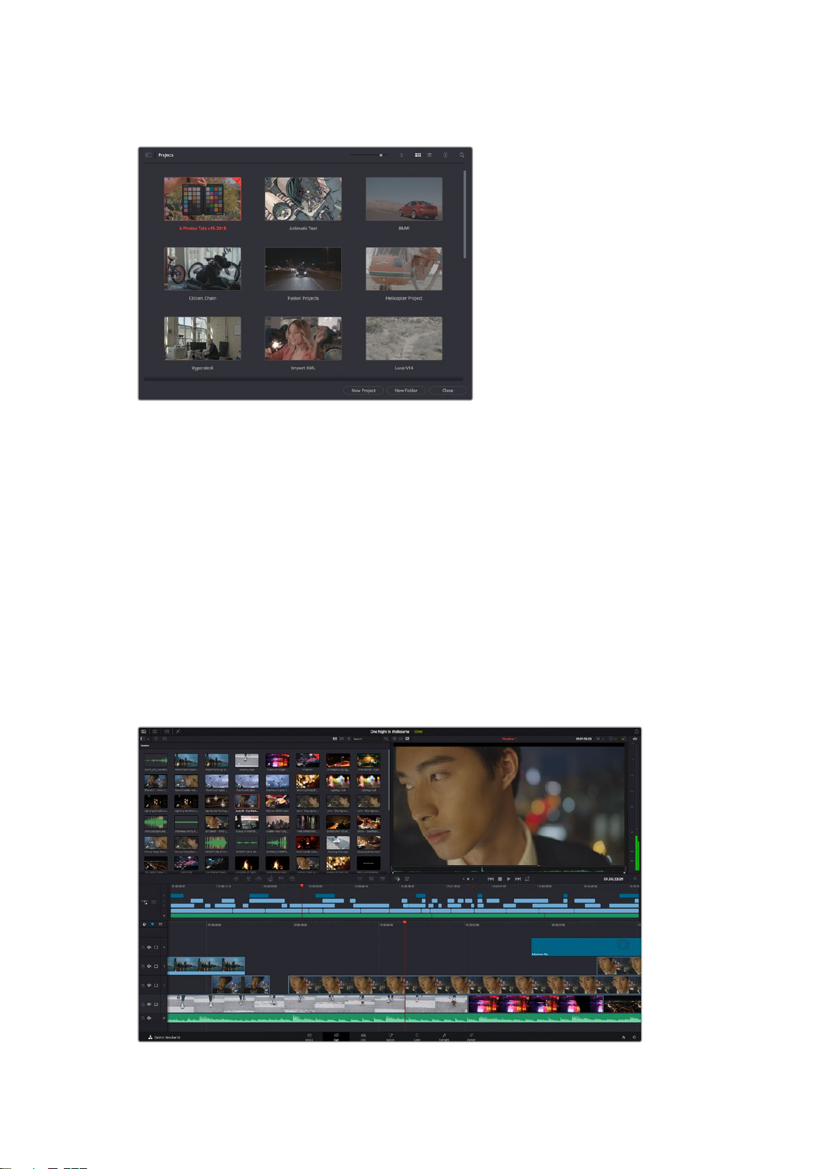
Using the ‘cut’ page, you can start working on your edit immediately.
The project manager shows all projects belonging to the current user
For more information about the Project Manager, refer to the DaVinci Resolve manual which is
available to download on the Blackmagic Design website support page.
Editing with the Cut Page
The ‘cut’ page gives you a fast, dynamic editing workflow that lets you quickly assemble, trim
and edit clips efficiently.
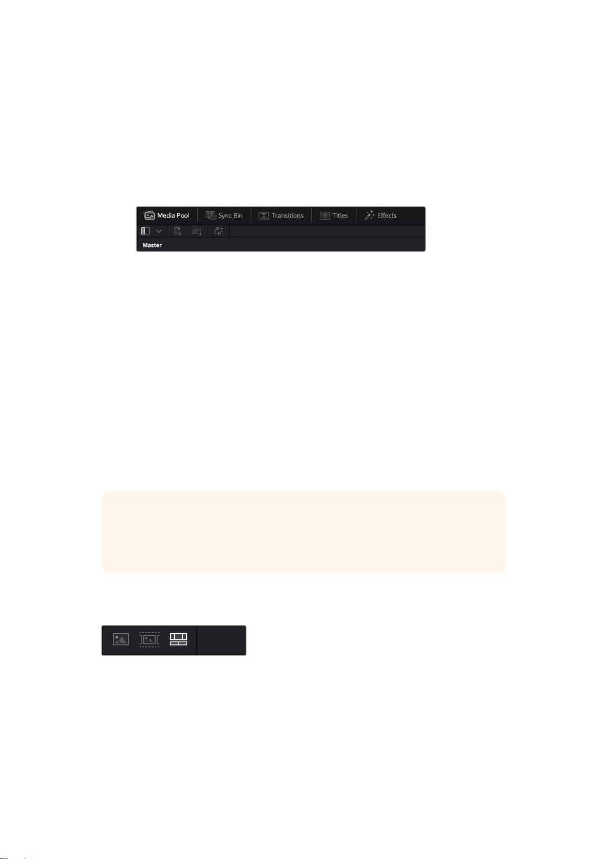
Two active timelines let you work with your entire edit plus a detailed area simultaneously.
This means you can drop clips anywhere on a large timeline, then refine your edit in a detailed
timeline within the same workspace. Using this workflow, you can edit on a laptop without
needing to zoom in and out and scroll as you work, which can be an enormous time saver.
The Cut Page Layout
When you open the cut page, you will see the media pool, viewer window and timeline.
These three primary windows give you complete control over your edit.
The ‘cut’ page default workspace, with the media pool in icon view
40Using DaVinci Resolve
Page 41
For more information on the Cut page, see the ‘Using the Cut Page’ chapter in the
DaVinci Resolve manual.
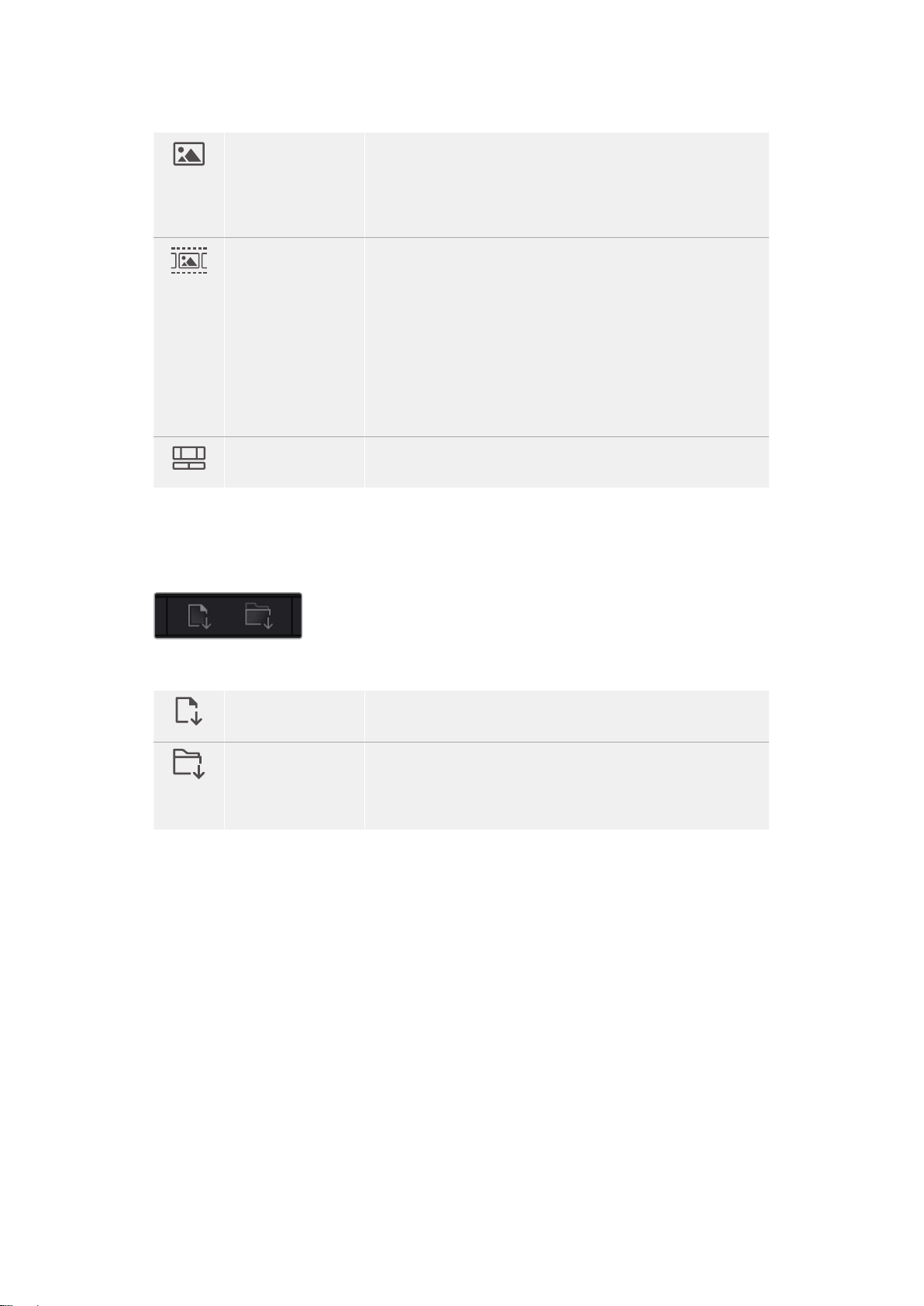
Media Tabs
At the top left corner of the user interface you will see five tabs.
Click on these tabs to open the media toolsets you will use when creating your edit.
For example, the first tab is the media pool and you can see it is already selected. The other
tabs are for the sync bin, media transitions, titles and effects.
Media Pool: The media pool contains all your clips, folders and files you imported using
the media page. You can also import files directly from the cut page, so you don’t have
to go back to the media page if you want to import a new clip.
Sync Bin: This powerful feature automatically syncs all your clips via timecode, date
and time so you can choose angles from all cameras on a multi camera project.
Transitions: If you click on the neighboring transitions tab, you will see all the video and
audio transitions you can use in your edit. These include common transitions such as
cross dissolves and motion wipes.
Titles: Next to transitions is the ‘titles’ tab. Here you can select the title type you
want to use. For example a scroll, standard text or lower thirds title. There are also a
list of Fusion templates you can use for more animated dynamic titles which can be
customized in DaVinci Resolve’s ‘Fusion’ page.
Effects: The fifth tab is the ‘effects’ tab. This provides all the different filters and effects
you can use to bring more life to your edit, for example customizable blurs, glows and
lens effects. There are many powerful effects to choose from and you can find them
quickly using the search tool.
TIP Use the search tool near the media tab icons to find the exact items you are
looking for. For example, if you have the transitions tab selected, type “dissolve” in the
search tool and only dissolve transition types will be shown in the viewer, making it
quicker for you to find the dissolve transition you want.
Viewer Tabs
In the top left corner of the viewer window you will see the viewer mode buttons.
The viewer mode buttons
These buttons control which viewer is currently being used, including ‘source clip’, ‘source tape’,
and ‘timeline’. These viewer modes give you an enormous amount of control when selecting
clips for your edit and it’s worth spending a moment to look at how they work.
41Using DaVinci Resolve
Page 42
Source Clip The source clip viewer displays a single clip from the media pool and
you can set in and out points along the entire length of the viewer
timeline. This gives you greater control. Select a source clip to view
by double clicking on a clip in the media pool, or dragging it into
theviewer.
Source Tape Source tape lets you view all the source clips in the media pool.
This powerful feature is helpful if you want to quickly search through
all your clips to find a specific event. As you scrub the playhead over
the clips, you will see their thumbnails selected in the media pool.
This means once you have found the clip you want to edit, you can
click on the source clip tab and its corresponding source clip will
appear in the viewer automatically.
The source tape viewer really lets you take advantage of non-linear
editing, giving you the freedom to work on your edit, find shots
quickly, try new ideas and stay in the moment.
Timeline The timeline viewer lets you view the edit timeline so you can play
back your project and refine your edits.
Importing Clips to the Media Pool
Now you can start importing media into your project. You can do this in the media pool window
of the cut page using the import tools at the top.
Select one of the import options to add media to your project
Import Media The import media option will import individual media files selected
from your storage location.
Import Media Folder To import a folder from your media storage, select the import folder
option. When importing a folder, DaVinci Resolve will keep the file
structure, treating each folder as a separate bin so you can navigate
between bins to find your videos and other media files.
To import media:
1 Click on the ‘import media’ or ‘import media folder’ icon.
2 Navigate to your media storage for the media you want to import.
3 Select the file or folder and click ‘open’.
Once you’ve added media to your project, it is a good time to save your changes. DaVinci
Resolve features a fast, on the go autosave called ‘live save’. Once you save you project once,
‘live save’ will save further changes as you make them, removing the risk of losing your work.
For more information on ‘live save’ and other auto save functions, refer to the DaVinci
Resolve Manual.
42Using DaVinci Resolve
Page 43
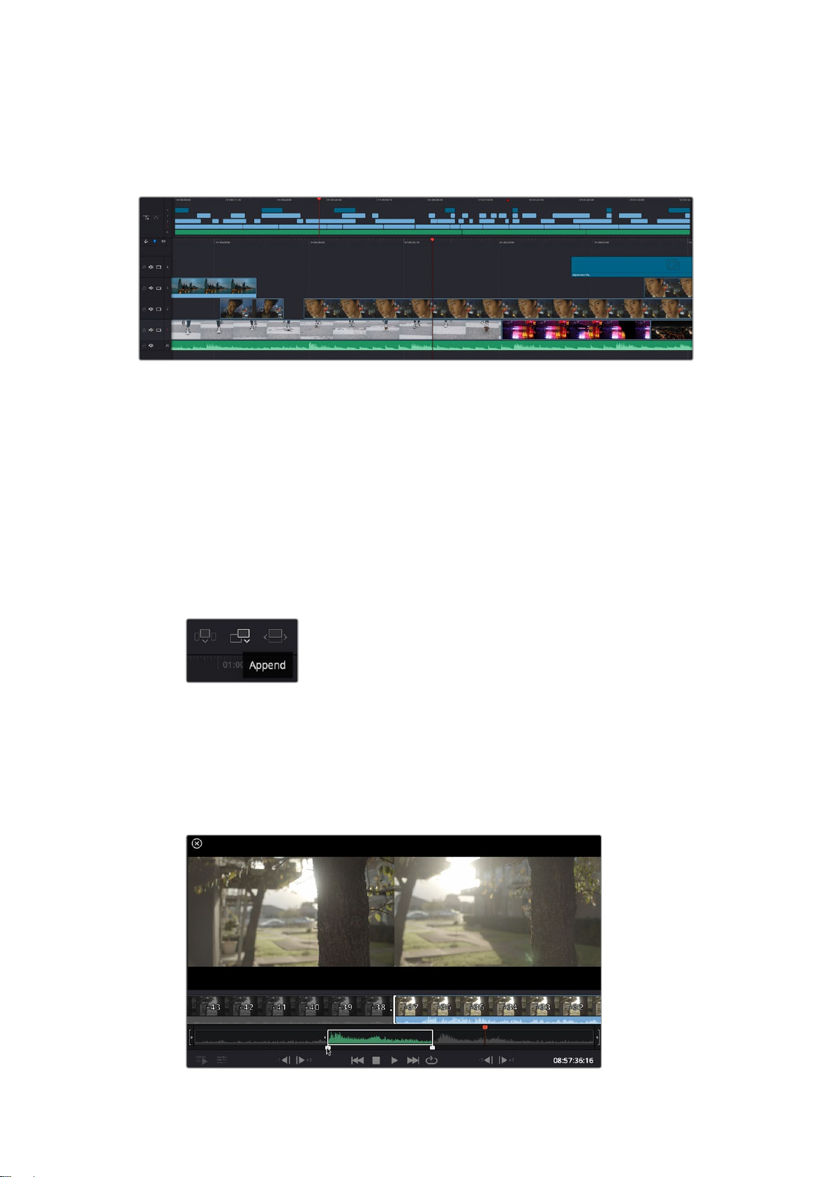
Adding Clips to the Timeline
Now that you are familiar with the media tabs and viewer mode buttons, you can open the
media pool and quickly start adding clips to your timeline.
The timeline of the cut page, comprising the upper timeline and the zoomed in timeline below
The timeline is where you will build your edit and is like a board with tracks you can attach clips
to, move them around and trim their edits. Tracks let you layer clips over others which gives you
more flexibility to try different edits and build transitions and effects. For example, you can try
an edit with a clip on one track without affecting other clips on tracks below it.
There are different ways to add clips to the timeline, such as smart insert, append, place on
top and more.
Appending Clips
When selecting takes and assembling an edit, you will likely want to add these shots to your
timeline one after the other. The append tool is perfect for this task and will get you editing
very fast.
Click on the append icon to quickly
addclips to the end of the last clip
To append a clip:
1 Double click on a clip in the media pool to open it in the viewer.
2 Using the scratch trim tool, drag the in and out points to select the precise duration of
your shot. You can also press the ‘i’ and ‘o’ keyboard shortcuts to set in and out points.
43Using DaVinci Resolve
Page 44
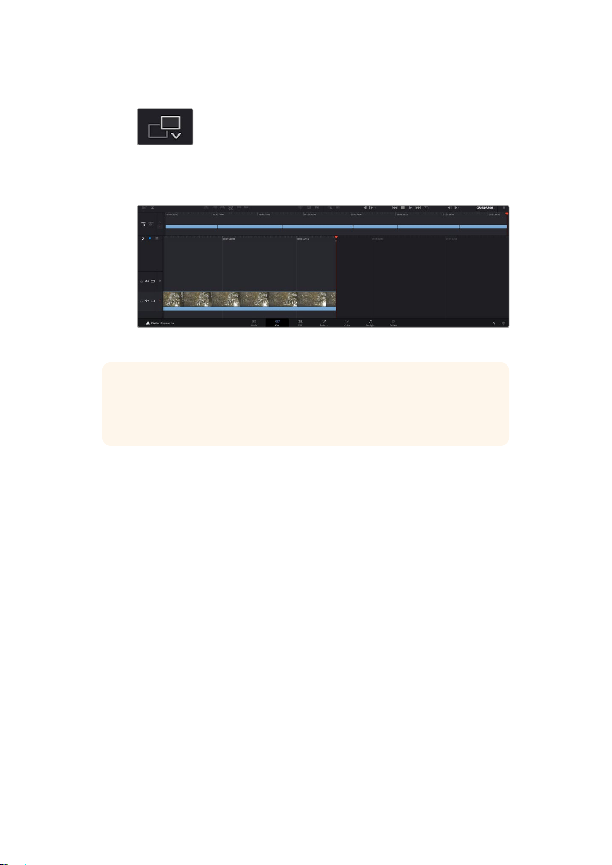
3 Now click the ‘append’ icon underneath the media pool.
Your first clip will be placed at the head of the timeline.
Repeat steps 1 to 3 to keep adding more clips and they will automatically append,
ensuring there are no gaps in the timeline.
Appending clips ensures there are no gaps between them on the timeline
TIP You can speed up the process further by assigning a keyboard shortcut to the
‘append’ icon. For example, if you assign the ‘P’ key, you can set your in and out points
using ‘I’ and ‘O’ then press ‘P’ to append the clip. Refer to the DaVinci Resolve manual
for information on how to assign shortcut keys.
Editing Clips on the Timeline
With clips added to the timeline, you have complete control to move them around and
trim edits.
To trim an edit, hover the mouse over the start or end of a clip, then click and drag it left or right.
For example, drag the end of the clip left or right to decrease or increase its duration. You might
notice that all clips after that edit will shift on the timeline to accommodate the new adjustment.
This is one way the ‘cut’ page helps to save you time.
You can even pick the clip up and drop it on a new video track in the large timeline without
having to zoom in or out. This speeds up the edit process because it minimizes time navigating
a long timeline.
After you have finished editing clips using the ‘cut’ page, you might want to add a title. The next
section will show you how.
Adding Titles
Placing a title on your timeline is easy and you have many options.
To see the different types of titles you can use, click on the ‘titles’ media tab at the top left
corner of the user interface. In the selection window you will see all the different title generators
you can use, from lower thirds, scrolls, to a standard text title. You can even add any of the
Fusion titles which are animated titles that you can customize.
A good example is to add a standard title.
44Using DaVinci Resolve
Page 45

To do this:
1 Click on the ‘text’ title and drag it onto the timeline. It doesn’t matter which timeline,
but for greater accuracy we recommend using the detailed timeline. The title will
automatically create a new video track for the title and will snap to the playhead.
2 Release the mouse and the title will appear on the new track. You can now move it or
change its duration like you would another video clip.
3 To edit the title, click on the new title clip and a ‘tools’ icon will appear underneath the
clip viewer. Click on the tools icon.
You will now see a row of tools you can use to modify the title clip. For example
transform, crop, dynamic zoom and more. For this example, click on the ‘title’ tool.
4 Now click ‘open inspector’.
This will open the inspector window where you can type in the title you want and edit the text
settings, for example tracking, line spacing, font type, color and more.
You have a lot of options to customize the title exactly how you want it. We recommend playing
with all the different settings to see how they can change the appearance and shape of
your title.
Color Correcting your Clips with the Color Page
Now with your clips on the timeline and titles added, you can start color correcting using the
‘color’ page. The color page is extremely powerful and will define the overall look of your film,
but for this example a good place to start is to neutralize all your clips so they are consistent.
You can also return to the ‘cut’ or ‘edit’ page at any time if you want to make changes to
your edit.
The color page lets you adjust the look of your edit and in many ways color correction is an art
form in itself. You are really adding emotion to your work when you add color correction. It’s an
incredibly creative part of the workflow and very satisfying when you learn these skills and can
see your work come alive! This is usually the first step and is referred to as primary color
correction, or adjusting the primaries. After primary color correction is done, you can then make
secondary color correction adjustments which is where you can make extremely precise color
adjustments of specific objects in your images. That is a lot of fun, but is normally done after
primaries because it helps make the process more efficient and you will get a better result!
First click on the ‘color’ tab to open the color page.
You’ll see the camera raw settings, color wheels, curves palettes and general color correction
tools as well as the preview and nodes window. Don’t feel overwhelmed by the vast array of
features in front of you, they are all there to help you get the most amazing looking pictures.
This getting started section will show the basics, but for more detailed information refer to the
relevant sections in the manual. They will show you exactly what all the tools are for and how to
use them in easy to follow steps. You’ll learn the same techniques the professionals use in high
end color correction facilities.
Generally, the first step for primary color correction is to optimize the levels for shadows, mid
tones and highlights in your clips. In other words adjust the ‘lift’, ‘gamma’ and ‘gain’ settings.
This will help get your pictures looking their brightest and best with a clean, balanced starting
point from where you can begin grading the ‘look’ of your film. To optimize the levels, it’s helpful
to use the scopes.
45Using DaVinci Resolve
Page 46
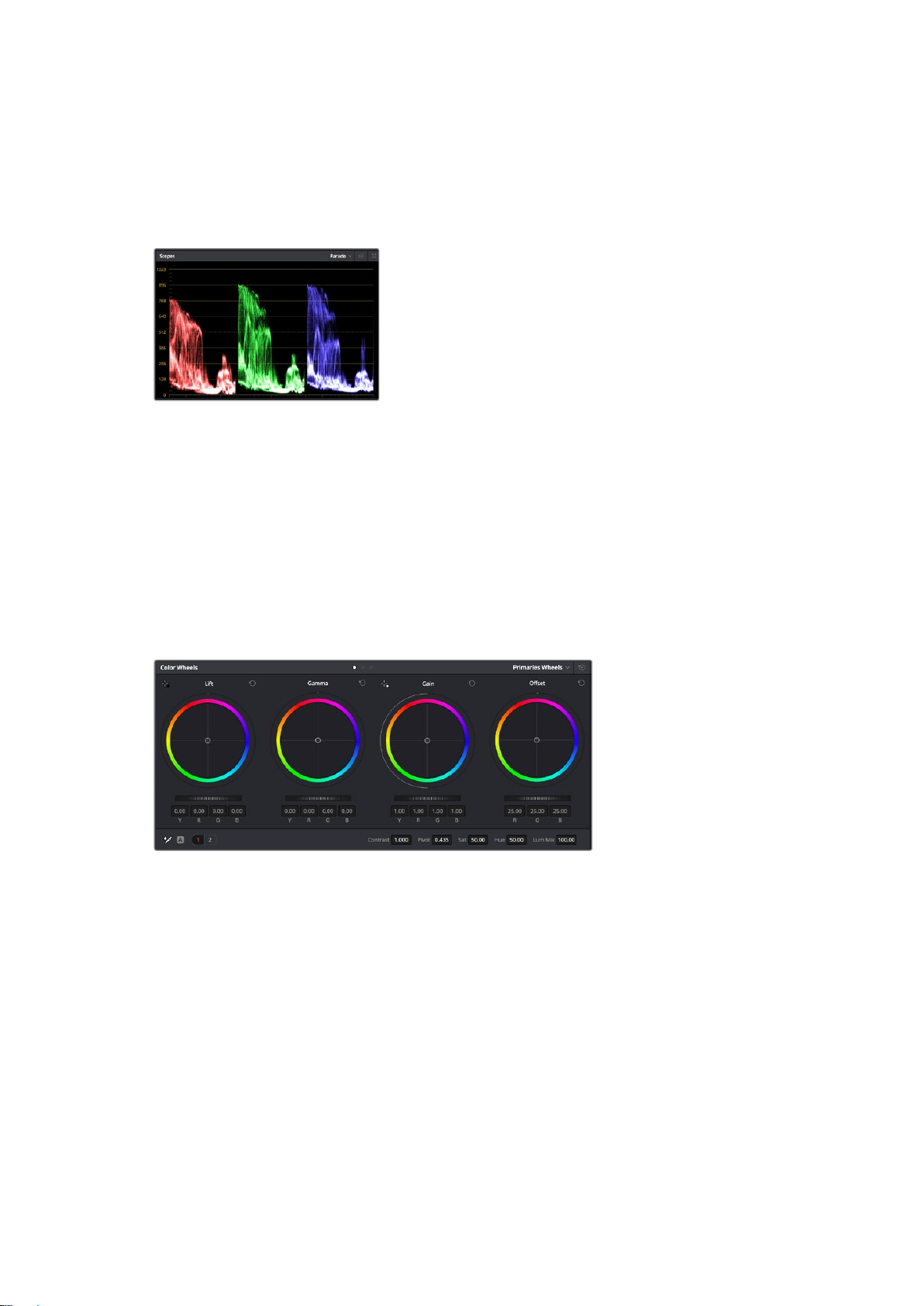
Using Scopes
Most colorists make creative color choices by focusing on the emotion and the look they want
their program to have and then simply work using the monitor to achieve that look. You can look
at everyday objects and how different types of light interact with them to generate ideas on
what you can do with your images and a little practice.
The parade scope helps you optimize
highlights, mid tones and shadows
Another way to color grade is to use the built in scopes to help you balance shots. You can
open a single video scope by clicking the ‘scope’ button, which is the second from the right on
the palette toolbar. You can choose to display a waveform, parade, vectorscope and histogram.
Using these scopes you can monitor your tonal balance, check the levels of your video to avoid
crushing your blacks and clipping the highlights, plus monitor any color cast in your clips.
The ‘color wheels’ palette contains the ‘lift’, ‘gamma’ and ‘gain’ controls which will generally
constitute your first adjustment. If you’ve previously had experience with color correction,
these should resemble controls you’ve seen in other applications for doing color and
contrast adjustments.
The ‘lift, ‘gamma’, ‘gain’ and ‘offset’ color wheels give you total control over the
color and tonal balance of your clips. To make a uniform adjustment to all colors for
each tonal region, drag the dial underneath the color wheels back and forth
For more accurate control of each color using a mouse, you can change the color wheels to
‘primaries bars’ which let you adjust each color and luminance channel for the lift, gamma and
gain controls separately. Simply select ‘primaries bars’ from the dropdown menu near the top
right of the color wheels.
Adjusting the ‘lift’: With your clip selected on the color timeline, click on the ‘lift’
dial underneath the first color wheel. Slide it back and forth and watch how it affects
your image. You’ll see the brightness of the dark regions of your picture increase
and decrease.
Set it to where you want the dark areas to look their best. If you decrease the lift too
much, you’ll lose details in the blacks and you can use the parade scope to help avoid
this. The optimal position for blacks on the waveform is just above the bottom line of
the parade scope.
46Using DaVinci Resolve
Page 47
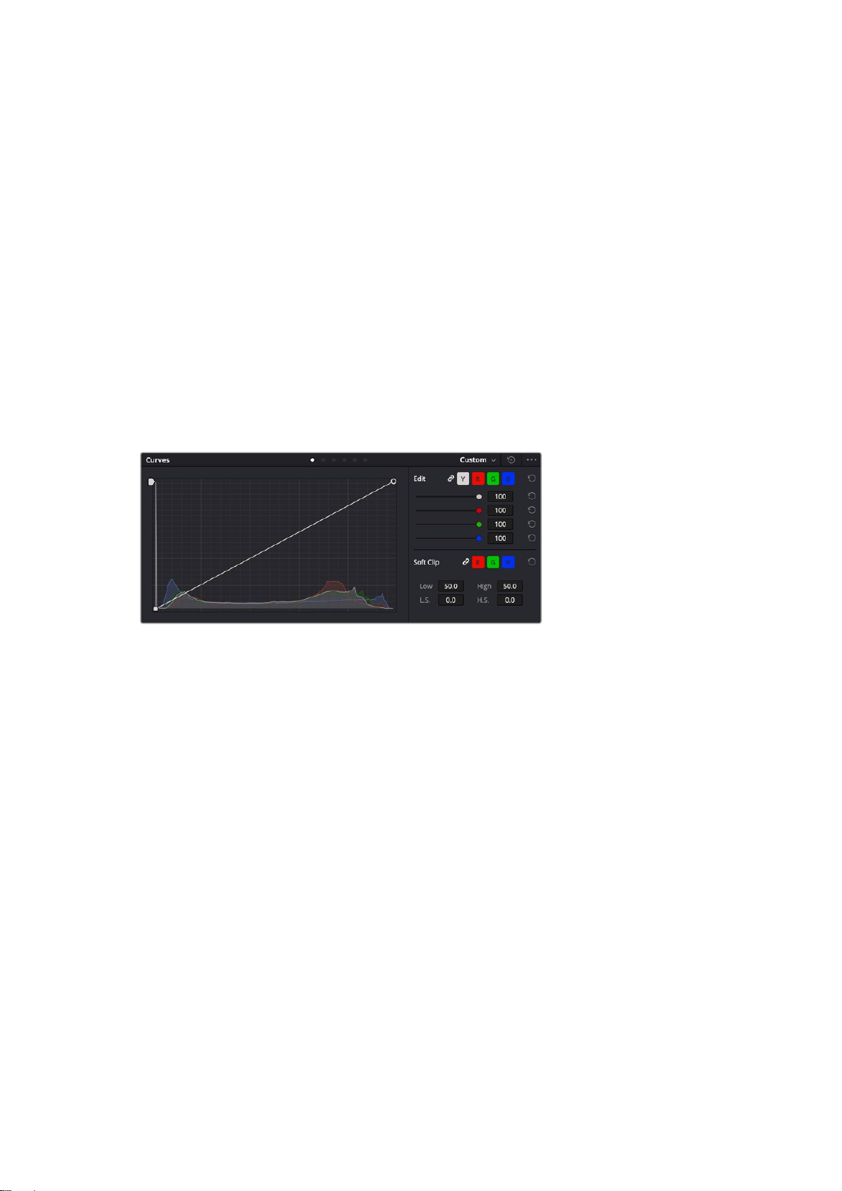
Adjusting the ‘gain’: Click on the ‘gain’ dial and slide it back and forth. This adjusts
the highlights which are the brightest areas of your clip. The highlights are shown on
the top section of the waveform on the parade scope. For a brightly lit shot, these are
best positioned just below the top line of the waveform scope. If the highlights rise
above the top line of the waveform scope, they will clip and you will lose details in the
brightest regions of your image.
Adjusting the ‘gamma’: Click on the ‘gamma’ dial underneath the color wheel and slide
it back and forth. Asyou increase the gamma you’ll see the brightness of the image
increase. Notice the middle section of the waveform will also move as you adjust the
gamma. This represents the mid tones of your clip. The optimal position for mid tones
generally falls between 50 to 70% on the waveform scope. However, this can be
subjective based on the look you are creating and the lighting conditions in the clip.
You can also use the curves palette to make primary color corrections. Simply click to create
control points on the diagonal line inside the curve graph, and drag them up or down to adjust
the master RGB contrast at different areas of image tonality. The optimum points to adjust are
the bottom third, mid, and top third of the curve line.
There are many more ways of doing primary color correction in DaVinci Resolve.
The curves palette is another tool you can use to make primary color corrections,
or enhance specific areas of your clip when using a power window
Secondary Color Correction
If you want to adjust a specific part of your image then you need to use secondary corrections.
The adjustments you have been doing up until now using the lift, gamma andgain adjustments
affect the whole image at the same time and so they are called primary color corrections.
However, if you need to adjust specific parts of your image, say for example you wanted to
improve the color in the grass in a scene, or you wanted to deepen the blue in a sky, then you
can use secondary corrections. Secondary color corrections are where you select a part of the
image and then adjust only that part. With nodes, you can stack multiple secondary corrections
so you can keep working parts of your image until everything is just right! You can even use
windows and tracking to allow the selections to follow movement in your images.
Qualifying a Color
Often you’ll find a specific color in your clip can be enhanced, for example grass by the side
ofa road, or the blue in a sky, or you may need to adjust color on a specific object to focus the
audience’s attention on it. You can easily do this by using the HSL qualifier tool.
47Using DaVinci Resolve
Page 48
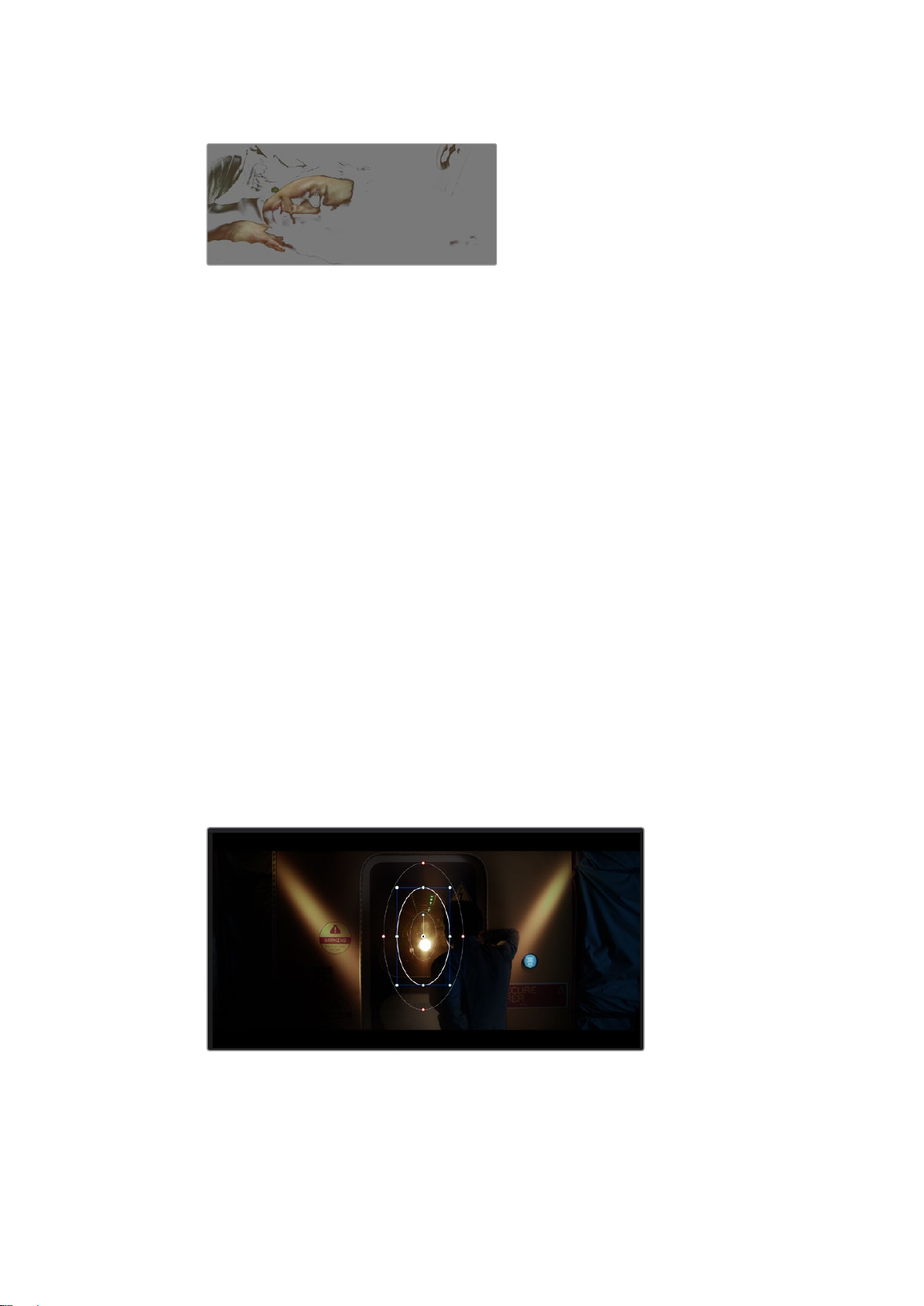
Using the HSL qualifier to select colors in your
image is helpful when you want to make areas of
your image ‘pop’, to add contrast, or to help draw the
audience’s attention to certain areas of your shot
To qualify a color:
1 Add a new serial node.
2 Open the ‘qualifier’ palette and make sure the ‘selection range’ picker tool is selected.
3 Click on the color in your clip you want to affect.
4 Usually you’ll need to make some adjustments to soften the edges of your selection
and limit the region to only the desired color. Click on the ‘highlight’ button above the
viewer to see yourselection.
5 Adjust the ‘width’ control in the ‘hue’ window to broaden or narrow your selection.
Experiment with the high, low and softness controls to see how to refine your selection.
Now you can make corrections to your selected color using the color wheels or custom curves.
Sometimes your selection can spill into areas of the shot you don’t want to affect. You can easily
mask out the unwanted areas using a power window. Simply create a new window and shape it
to select only the area of color you want. If your selected color moves in the shot, you can use
the tracking feature to track your power window.
Adding a Power Window
Power windows are an extremely effective secondary color correction tool that can be used to
isolate specific regions of your clips. These regions don’t have to be static, but can be tracked
to move with a camera pan, tilt or rotation, plus the movement of the region itself.
Use power windows to mask out areas you don’t want
to be affected by the HSL qualifier secondary adjustments
48Using DaVinci Resolve
Page 49
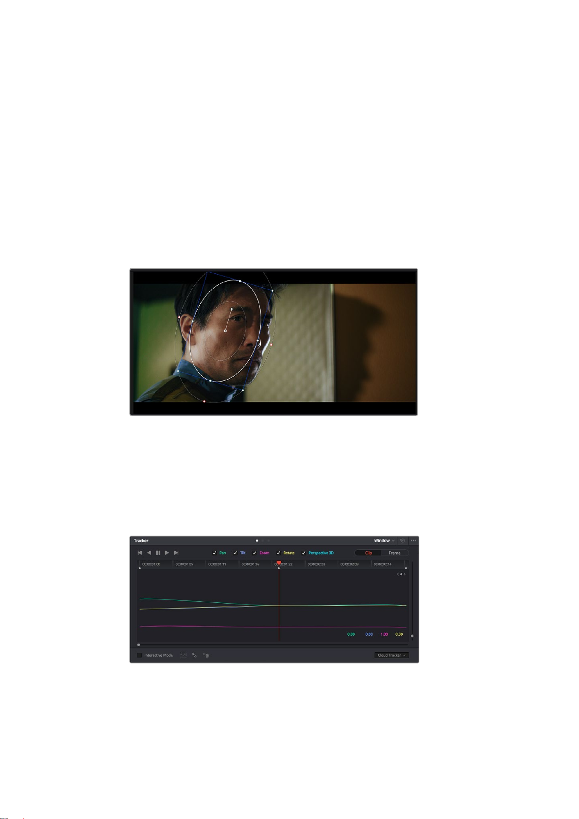
For example, you can track a window on a person in order to make color and contrast changes
just to that person without affecting his or her surroundings. By making corrections like this you
can influence the audience’s attention on areas you want them to notice.
To add a power window to your clip:
1 Add a new serial node.
2 Open the ‘window’ palette and select a window shape by clicking on a shape icon.
Your selected window shape will appear on the node.
3 Resize the shape by clicking and dragging the blue points around the shape. The red
points adjust the edge softness. You can position the shape by clicking the center
point and moving it to the area you want to isolate. Rotate the window using the point
connected to the center.
Now you can make color corrections to your image in just the area you want.
Power windows let you make secondary corrections to specific parts of your image
Tracking a Window
The camera, object or area in your shot may be moving, so to make sure your window stays on
your selected object or area, you can use DaVinci Resolve’s powerful tracking feature. The
tracker analyzes the pan, tilt, zoom and rotation of the camera or object in your clip so you can
match your windows to that movement. If this isn’t done, your correction can move off the
selected target and call attention to itself, which you probably don’t want.
You can track objects or areas in your clip using the tracker
feature so power windows can follow the action
49Using DaVinci Resolve
Page 50
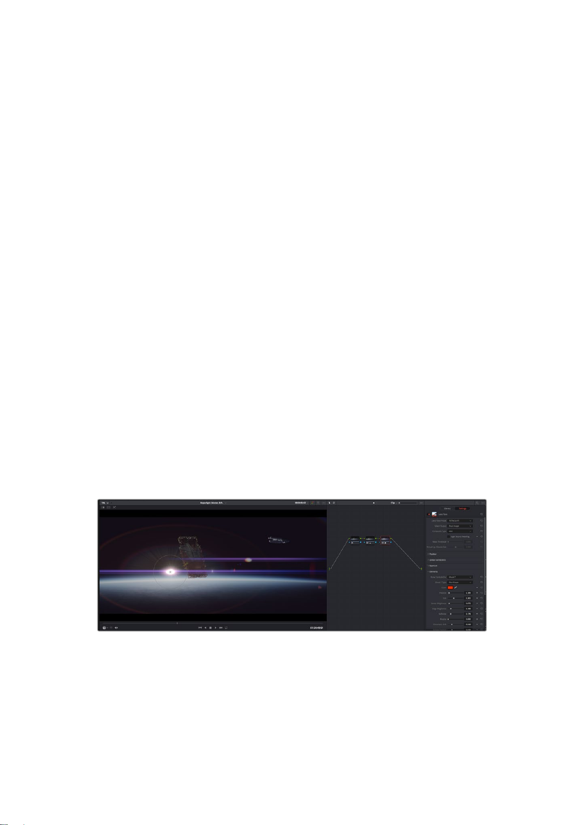
To track a window to a moving object:
1 Create a new serial node and add a power window.
2 Go to the start of your clip and position and size the window to highlight just the object
or area you want.
3 Open the ‘tracker’ palette. Select the pan, tilt, zoom, rotate, and perspective
3D settings appropriate for the movement in your clip by checking or unchecking
the relevant ‘analyze’ checkboxes.
4 Click on the ‘forward’ arrow to the left of the checkboxes. DaVinci Resolve will now
apply a cluster of tracking points on your clip and then step through the frames to
analyze the movement. When the tracking is done, your power window will follow the
path of the movement in your clip.
Most of the time automatic tracking is successful, but scenes can be complex and sometimes
an object can pass in front of your selected area, interrupting or affecting your track. This can
be solved manually using the keyframe editor. Refer to the DaVinci Resolve manual to
find out more.
Using Plugins
While making secondary color corrections you can also add ResolveFX or OpenFX plugins to
create fast, interesting looks and effects using the ‘color’ page, or imaginative transitions and
effects on your clips on the ‘edit’ page. ResolveFX are installed with DaVinci Resolve, OFX
plugins can be purchased and downloaded from third party suppliers.
After installing a set of OFX plugins, you can access them or ResolveFX plugins on the color
page by opening the OpenFX inspector to the right of the ‘node editor’. Once you create a new
serial node, simply click the ‘OpenFX’ button to open the FX library and drag and drop a plugin
onto the new node. If the plugin has editable settings, you can adjust these in the adjoining
‘settings’ panel.
In the ‘edit’ page you can add plugin filters, generators and transitions to clips by opening the
‘OpenFX’ panel in the ‘effects library’ and dragging your selected plugin onto the video clip or
track above your clip on the timeline depending on the plugin requirements.
OFX plugins are a quick and easy way to create an imaginative and interesting look
50Using DaVinci Resolve
Page 51
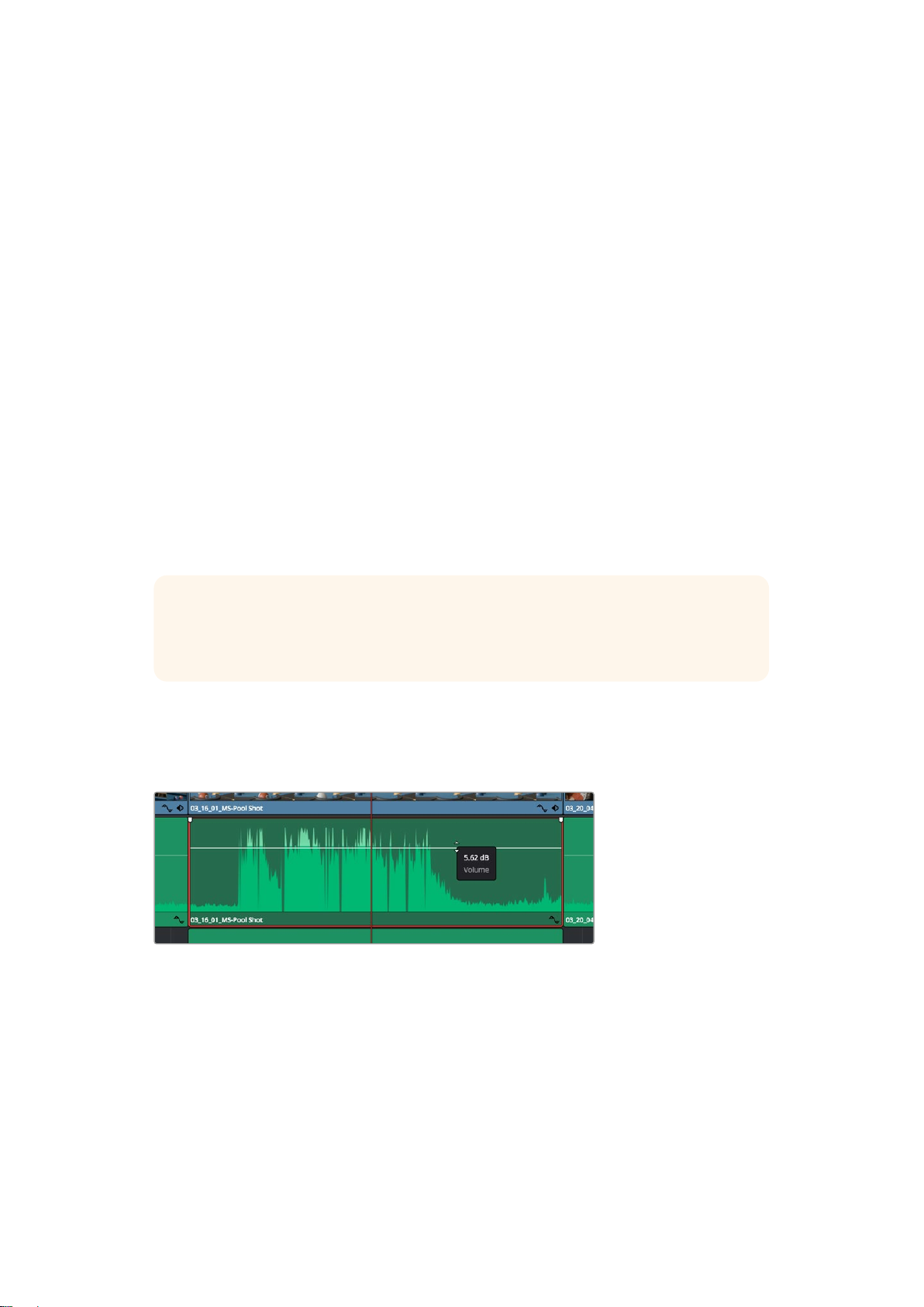
Mixing Your Audio
Mixing Audio in the Edit Page
Once you have edited and color corrected your project, you can begin to mix your audio.
DaVinciResolve has a helpful set of features for editing, mixing and mastering audio for your
project directly in the ‘edit’ page. For projects requiring more advanced audio tools, the
Fairlight page provides you with a full audio post production environment. If you are already
familiar with the edit page and want to move straight to Fairlight, skip this section and move
onto the next.
Adding Audio Tracks
If you are working in the edit page and want to mix a basic sound edit with lots of sound effects
and music, you can easily add more audio tracks when you need them. This can be helpful
when building your sound, and separating your audio elements into individual tracks, for
example, dialogue, sound effects and music.
To Add an Audio Track to the Edit Page
Right click next to the name of any audio track on your timeline and select ‘add track’ and
choose from the options, including ‘mono’, ‘stereo’, and ‘5.1’. This will add the track to the
bottom of the track list. Alternatively select ‘add tracks’ and select the position you would like
the new track or multiple tracks placed.
Your new audio track will appear on the timeline.
TIP If you wish to change the type of track after creating it, right click next to the name
of the track and select ‘change track type to’ and select the type of audio track you
want, such as stereo, mono or 5.1.
Adjusting Audio Levels in the Timeline
Each clip of audio in the timeline has a volume overlay that lets you set that clip’s level by simply
dragging it up or down with the pointer. This overlay corresponds to the Volume parameter in
the Inspector.
Dragging a volume overlay to adjust the clip level
For projects requiring more advanced audio tools, the Fairlight page provides you with a full
audio post production environment.
51Using DaVinci Resolve
Page 52
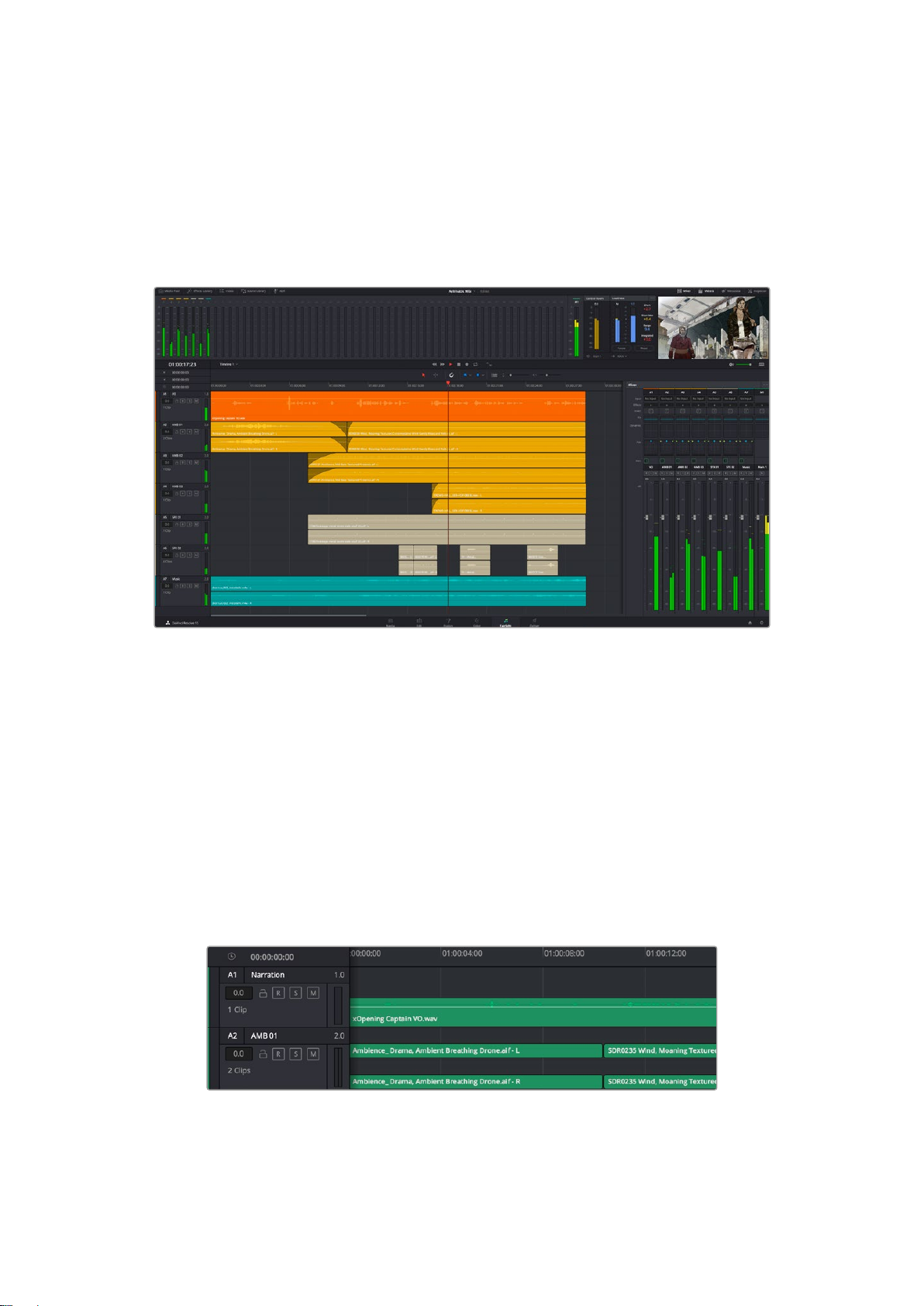
The Fairlight Page
The ‘Fairlight’ page in DaVinci Resolve is where you adjust your project audio. In single
monitormode, this page gives you an optimized look at the audio tracks of your project, with
anexpanded mixer and custom monitoring controls that make it easy to evaluate and adjust
levels in order to create a smooth and harmonious mix. Don’t feel overwhelmed by the vast
array of features in front of you, they are all there to help you deliver the best audio quality
foryour project.
This guide provides a basic overview of the features on the Fairlight page, but to learn more
about all the details for each feature, refer to the DaVinci Resolve manual. The DaVinci Resolve
manual provides details on the purpose of each tool and describes how to use them in easy to
follow steps.
The Audio Timeline
Track Header: At the left of each track is a header area that displays the track number,
track name, track color, audio channels, fader value and audio meters. The track
header also contains different controls for locking and unlocking tracks, plus solo and
muting controls. These controls can help to keep your tracks organized, and let you
preview individual tracks one at a time.
Tracks: Each track on the Fairlight page is divided into lanes, which show each
individual channel of clip audio for editing and mixing. The edit page hides these
individual audio channels, displaying only a single clip in the timeline to make it easier
to edit multi channel sources without needing to manage a huge number of tracks.
The track header on track A1 indicates a mono track with a single lane for mono audio,
and the A2 track header indicates a stereo track with two lanes to accommodate stereo audio
52Using DaVinci Resolve
Page 53
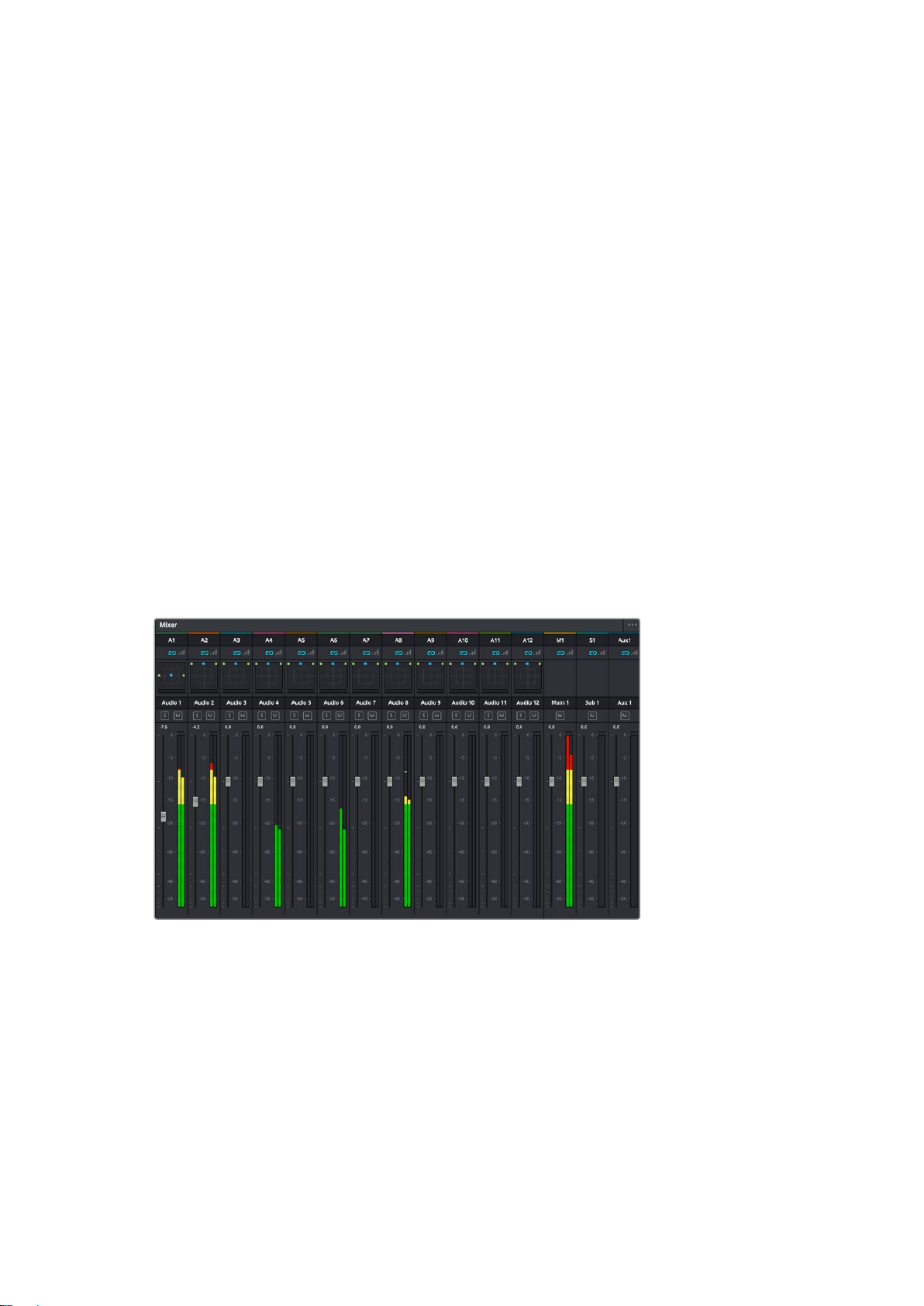
What is a Bus?
A bus is essentially a destination channel to which you can route multiple audio tracks from the
timeline, so that they are mixed together into a single signal that can be controlled via a single
channel strip.
Main Bus: ‘Main busses’ are typically the primary output of a program and each new
project you create starts out with a single ‘main bus’, to which all tracks are routed by
default. The ‘main bus’ combines all of the tracks in the timeline into one signal so that
you can adjust the overall level of the audio mix once you have adjusted the level of
each individual track.
Sub Bus: ‘Sub busses’ allow you to combine multiple tracks of audio that belong to the
same category such as dialogue, music or effects so that everything in that category
can be mixed as a single audio signal. For example, if you have five dialogue tracks,
you can route the output of all five dialogue tracks to a ‘submix bus’, and the level of all
dialogue can then be mixed with a single set of controls. This submix can be rendered
separately or sent to the main bus for render.
The Mixer
Each audio track in your timeline corresponds to an individual channel strip in the Mixer, and by
default there’s a single strip on the right for the ‘main bus’ labeled ‘M1’. Additional channel strips
will appear on the right hand side with a set of controls for each additional ‘main’ and ‘submix
bus’ you create. A set of graphical controls allows you to assign track channels to output
channels, adjust EQ and dynamics, set levels and record automation, pan stereo and surround
audio, and mute and solo tracks.
The audio mixer, with channel strips corresponding to the tracks in the timeline
Using the Equalizer to Enhance your Audio
After adjusting the audio levels of your audio clips in your project, you may find that the audio
needs further finessing. In some cases you may find that the dialogue, music and sound effects
are competing for the same frequency on the audio spectrum, making your audio too busy and
unclear. This is where using EQ can help, as it allows you to specify the parts of the audio
spectrum that each track occupies. You can also use an equalizer to help remove unwanted
elements from your audio by isolating and reducing the level on particular frequencies that
contain low rumbles, hums, wind noise and hiss, or simply to improve the overall quality of your
sound so it is more pleasing to listen to.
53Using DaVinci Resolve
Page 54
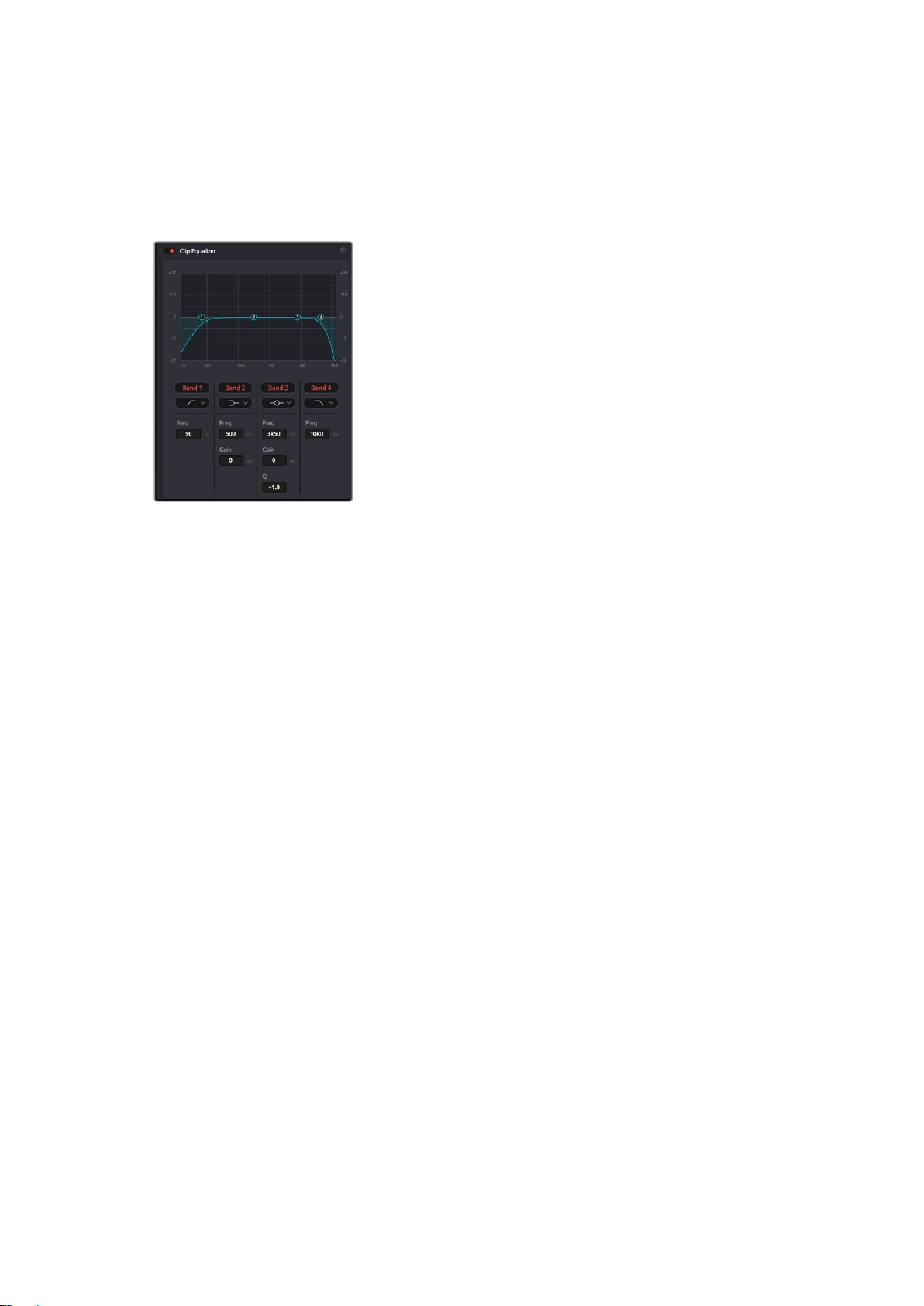
DaVinci Resolve provides EQ filters that can be applied at a clip level to each individual clip or
at the track level to affect entire tracks. Each audio clip in the timeline has a four band equalizer
in the inspector panel, and each track has a 6 band parametric equalizer in the mixer panel. The
graphical and numeric controls for boosting or attenuating different ranges of frequencies, and
different filter types allow you to define the shape of the EQ curve.
The four band equalizer can be applied
to every clip in the timeline
Outer bands let you make band filter adjustments using hi-shelf, lo-shelf, hi-pass and lo-pass
filters. A pass filter affects all the frequencies above or below a particular frequency, by
removing those frequencies completely from the signal. For example, a high pass filter will
allowthe high frequencies to pass through the filter while cutting the low frequencies.
Anyfrequencies outside the cutoff frequency are cut gradually in a downward sloping curve.
A shelf filter is less aggressive, and is useful when you want to shape the overall top end or low
end of the signal without completely removing those frequencies. The shelf filter boosts or cuts
the target frequency and every frequency either above or below it evenly, depending on
whether you use a high shelf or low shelf.
The middle sets of band controls let you make a wide variety of equalization adjustments, and
can be switched between lo-shelf, bell, notch, and hi-shelf filtering options.
Bell: Bell filters boost or cut frequencies around a given center point of the bell curve,
and as the name suggests the shape of the curve is like a bell.
Notch: Notch filters allow you to specifically target a very narrow range of frequencies.
For example, removing a mains hum at 50 or 60Hz.
Lo-Shelf: Low shelf filters boost or cut the target frequency at the low end, and every
frequency below it
Hi-Shelf: High shelf filters boost or cut the target frequency at the high end, and every
frequency above it
To add EQ to an individual clip:
1 Select the clip in the timeline that you want to add the EQ filter to.
2 Click on the inspector and then click the ‘clip equalizer’ enable button.
54Using DaVinci Resolve
Page 55
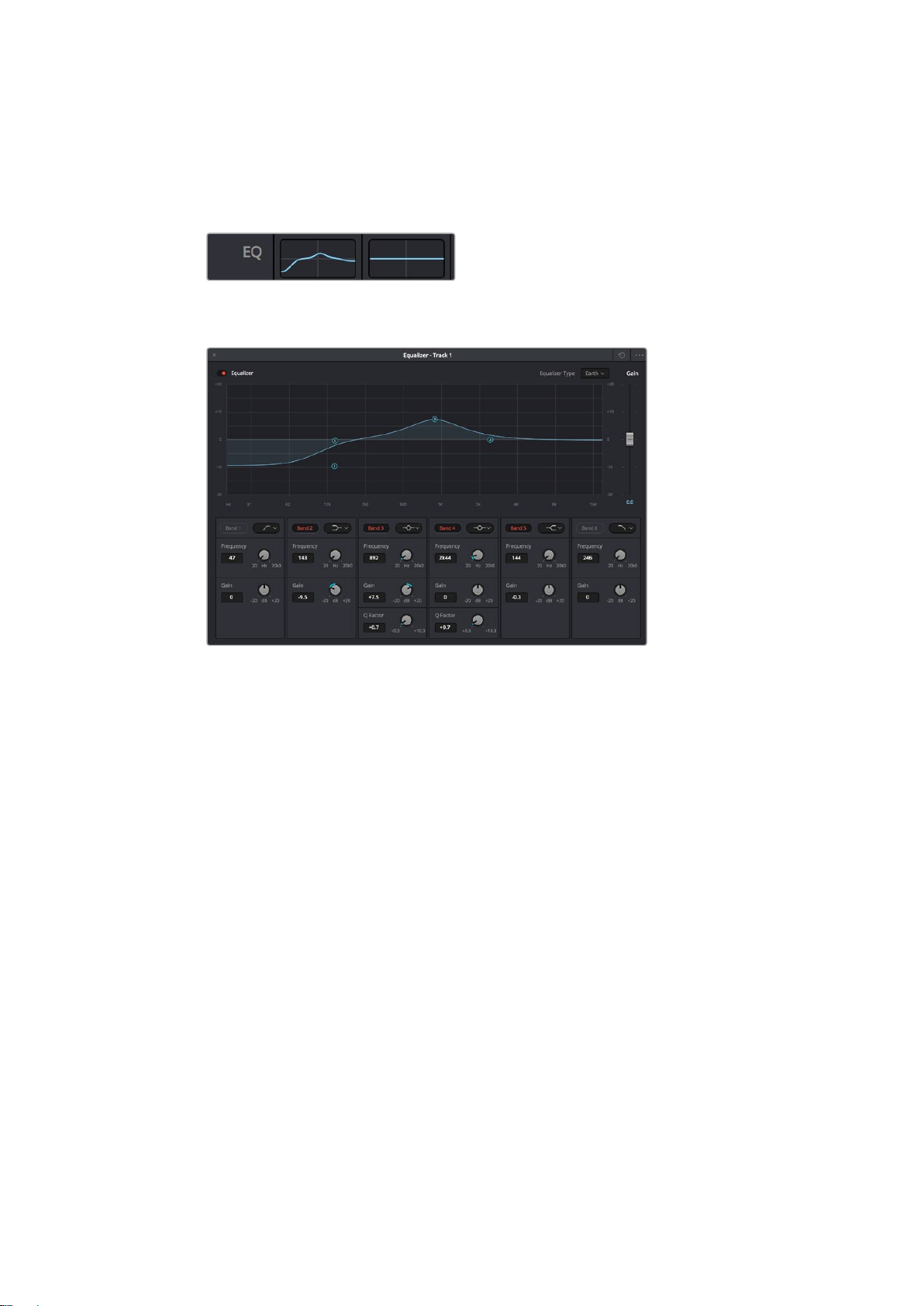
To add EQ to a track:
1 Double click in the EQ section for one of your tracks in the mixer to open the equalizer
for that track.
2 Select the band filter type from the dropdown menu for the band you want to adjust.
The EQ section in the mixer panel indicating
an EQ curve has been applied to track one
The 6 Band parametric equalizer that can be applied to every track
Once you have added EQ to your clip or track, you can adjust the EQ for each band. Note that
controls may vary depending on which band filter type is selected.
To adjust the EQ for a band filter:
1 Select the band filter type from the dropdown menu for the band you want to adjust.
2 Adjust the ‘frequency’ value to select the center frequency of the EQ adjustment.
3 Adjust the ‘gain’ value to boost or attenuate the frequencies governed by that band.
4 Use the ‘Q factor’ value to adjust the width of affected frequencies.
Use the reset button to reset all controls in the EQ window to their defaults.
Fairlight has many controls you can use to improve the quality of each audio track. You can add
more tracks and arrange buses to organize them, plus add effects like delay or reverb, and
generally perfect your audio mix.
Adding VFX and Compositing on the Fusion Page
Now that you have completed your edit, you can open the Fusion page to add 2D or 3D visual
effects and motion graphics right within DaVinci Resolve. Unlike layer based compositing
software, Fusion uses nodes, giving you the freedom to build complex effects while routing
image data in any direction. The nodes window clearly shows every tool used along the way.
Ifyou have experienced the node workflow in the color page, this will feel familiar to you.
55Using DaVinci Resolve
Page 56
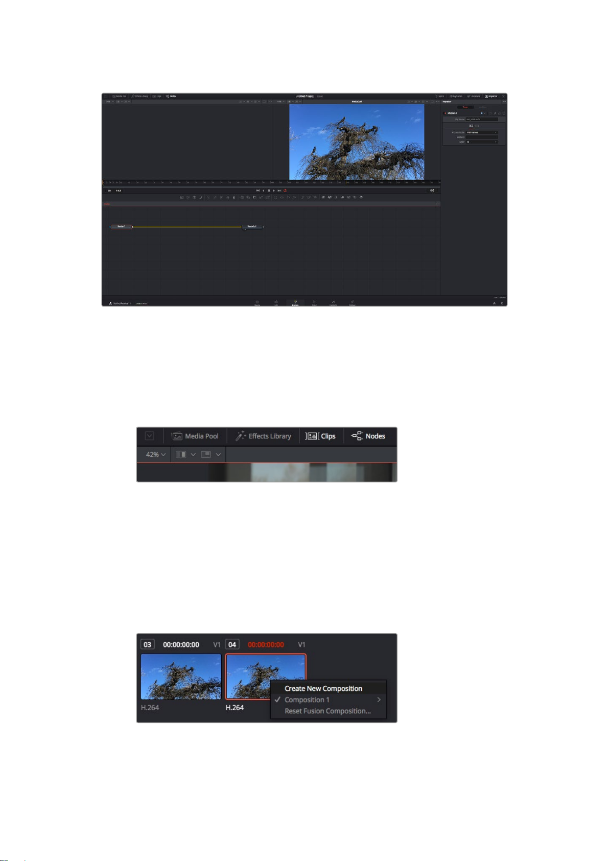
The Fusion Page
The Fusion page features 2 viewer windows across the top with transport controls to view your
media, an inspector window to the right to access tool settings, and a nodes window at the
bottom where you build your composition. While the viewers and transport controls are always
visible, clicking on the icons on the interface toolbar at the very top of the display will let you
show or hide the nodes and inspector windows, or reveal or hide additional windows including
the effects library and editors for spline and keyframes.
Media Pool: The media pool functions the same way as it appears in the edit page.
Simply drag additional media from your bins directly to your composition.
Effects Library: The effects library is where you will find your Fusion tools and
templates sorted into categories including particle, tracking, filters and generators.
You can either click on the tool or drag it to the nodes area to add it to your
composition. The media pool and effects library take up the same screen area, so you
can swap between the two to keep your viewers as large as possible.
Clips: Clicking the clips tab will reveal or hide thumbnails representing clips on your
timeline. The thumbnails are located underneath the nodes editor, letting you instantly
navigate to other clips.
Create a new version of your composition by right clicking on a
thumbnail and selecting ‘create new composition’.
56Using DaVinci Resolve
Page 57
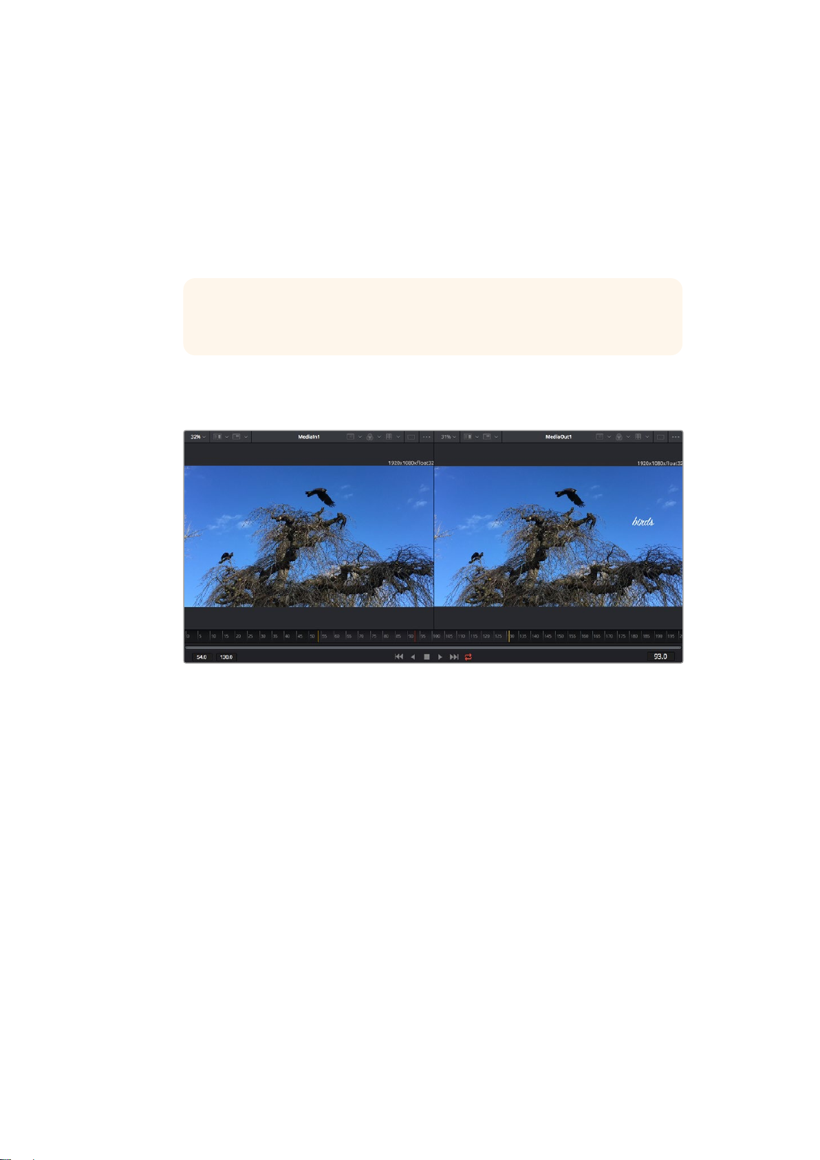
Viewers: The viewers are always visible and let you see the different views of your
composition, for example an overall 3D perspective via the merge 3D node, a camera
output, oryour final render output. These viewers also let you see how your changes
are affecting aspecific element.
You can choose which nodes to view by clicking on a node and typing ‘1’ for the left
viewer or ‘2’ for the right viewer. White button icons appear beneath the node to let
you know which viewer itis assigned to. If you’re using external video monitoring, there
will be a third button available to route your media to your external video monitor.
TIP You can also assign a node to a viewer by dragging the node
into the viewer itself.
The transport controls underneath the viewers let you skip to the start or end of the
clip, play forward or reverse, or stop playback. The time ruler displays the entire range
of a clip, with yellow marks indicating the in and out points.
The yellow marks on the time ruler indicate your clip’s in and out points on your
timeline. If you are using a Fusion clip or compound clip, the time ruler will only show
you the duration of the clip as it appears on the timeline, without handles.
Nodes: The nodes window is the heart of the Fusion page where you build your node
tree byconnecting tools together from one node’s output to another node’s input.
Thisarea will change size depending on which editors are open, for example the spline
or keyframes editor. A toolbar atthe top of the nodes area features the most commonly
used tools for fast access.
Spline: When the spline editor is open, it will appear to the right of the nodes window.
This editor lets you make precise adjustments to each node, such as smoothing the
animation between two keyframes using bezier curves.
Keyframes: Keyframes for each tool can be added, removed or modified using the
keyframes editor. This also appears to the right of the nodes viewer.
Metadata: The metadata window will show you metadata available for the active clip,
including the codec, frame rate and timecode.
Inspector: The inspector in the top right corner displays all settings and modifiers
available for one or more selected nodes. Additional tab options will appear to provide
quick access to other settings for nodes sorted by category.
57Using DaVinci Resolve
Page 58
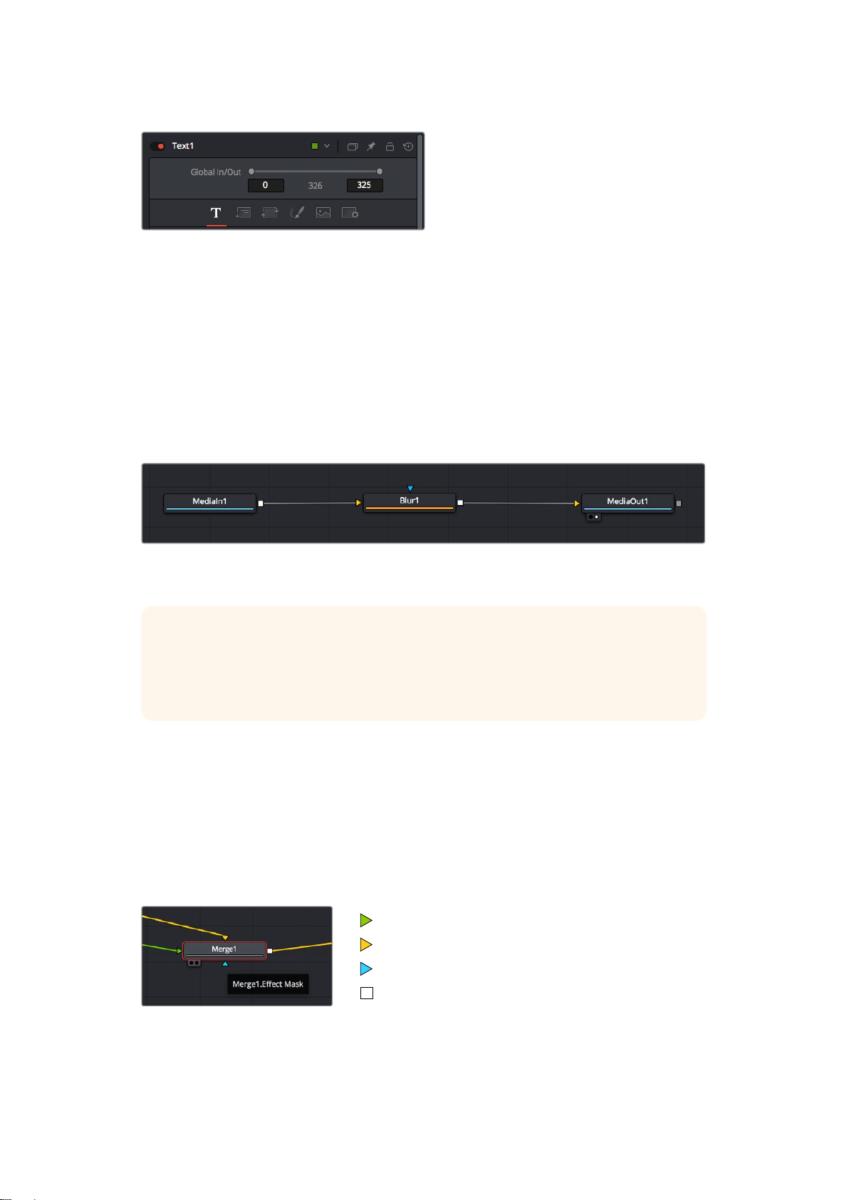
The text inspector contains additional tabs for text,
layout, transform, shading, image and settings.
Getting Started with Fusion
To get started with Fusion, simply position your playhead over any clip on your timeline and
click on the ‘Fusion’ tab to open the Fusion page.
On the Fusion page, your clip is immediately available in a media input node labelled ‘MediaIn’.
Every composition will begin with a ‘mediain’ and a ‘mediaout’ node. This mediain node
represents the top most clip of your timeline at the playhead, and ignores any clips underneath.
Any adjustments you’ve applied to the clip on the edit page, such as transform tools and
cropping changes, are also included.
The media output node, named ‘MediaOut’, is the node that sends the output
back to your timeline on DaVinci Resolve’s edit page.
TIP ResolveFX or OFX plug-ins applied to clips in the edit page are not applied in
the Fusion page. This is because Fusion effects occur prior to color correction and
OFX/ResolveFX processing. If you want OFX applied before Fusion effects, right click
the clip in the edit page and select ‘new fusion clip’ before clicking on the Fusion page.
Understanding Nodes
It can be helpful to think of each node as a visual icon representing a single tool or effect.
Nodes are connected to other nodes to build the overall composition, much like ingredients
inacake. It’s important to understand the inputs and outputs of each node as this will help you
navigate the flow of your composition while building detailed visual effects.
Some tools have multiple inputs and outputs you can connect to other nodes. The merge node,
for example, lets you attach a foreground input, background input, and a mask input for
mattes or keys.
foreground input
background input
effect mask input
output
58Using DaVinci Resolve
Page 59
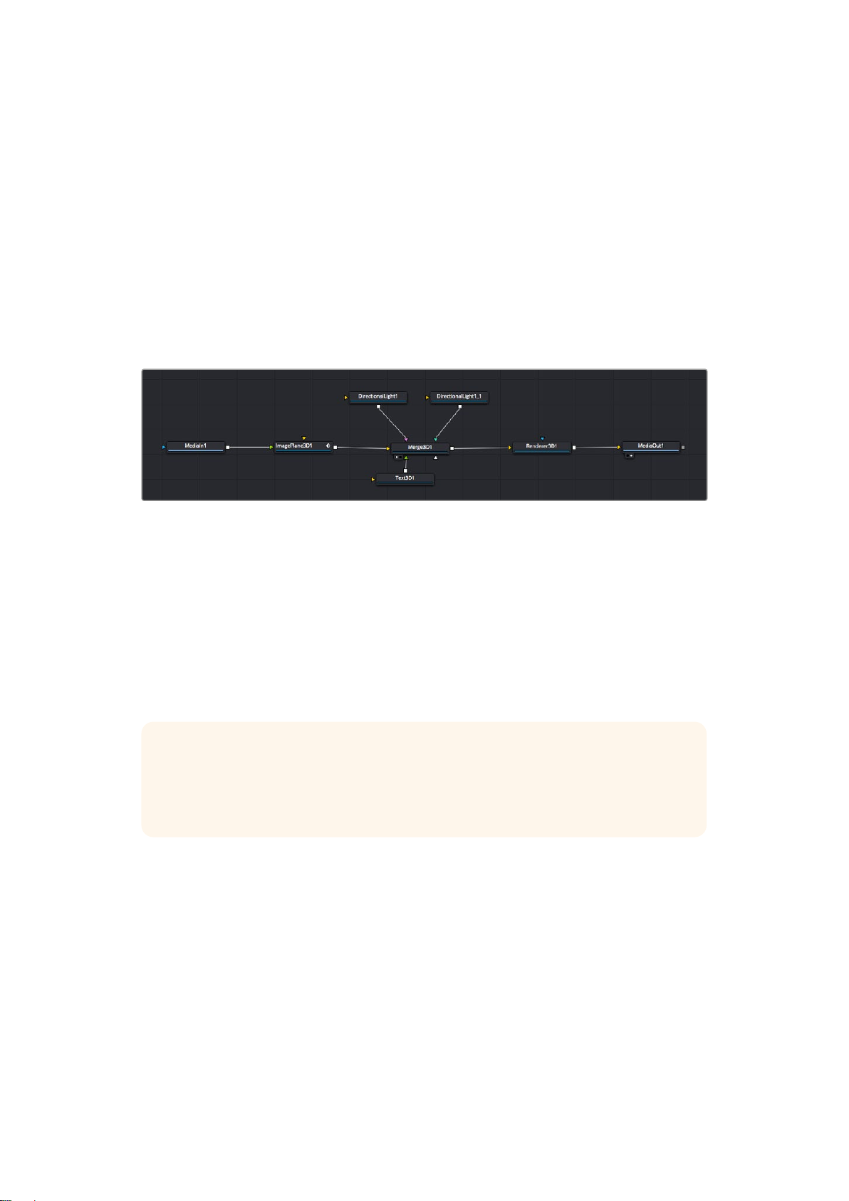
Multiple outputs on nodes means a single node can connect to many different nodes in your
composition, so you don’t have to duplicate clips as you would in layer based software.
Arrows on the line between connected nodes are a great visual indicator to show you which
direction the image data is flowing.
Adding Nodes to the Node Editor
Adding effects is as simple as placing nodes on the line between the ‘mediain’ and
‘mediaout’ nodes.
There are a few ways you can do this. You can hold down the shift button and drop a node
between two nodes, or click on the node you want to attach an effect to and select the
tool you want to add. The new node will automatically connect to the tool selected. You can
also add a node anywhere on the node window and manually connect nodes by dragging the
output of one to the input on another.
The most commonly used tool is the 2D or 3D merge node. This node is like
a central hub that combines tools on the node editor into a single output.
The merge node has controls for how the inputs are managed, including settings for size,
position, and blend. These settings are all accessible in the inspector panel when the merge
node is selected.
The toolbar above the node panel contains the most commonly used tools as icons that you
can either click on to add the node, or drag the tool to the node panel. If you want to see all the
complete tools available, click on the ‘effects library’ in the top left corner and expand the ‘tools’
option. Here you’ll find all the tools sorted by category, as well as a set of pre-built ‘templates’
you can use, for example lens flares, shaders and backgrounds.
TIP Once you’re familiar with the tool names, you can hold down ‘shift’ and press
‘spacebar’ on your keyboard and a ‘select tools’ menu will appear. As you type the tool
name, the menu will suggest the relevant tool. This is a very fast way to select the tool
you want.
Adjusting Nodes Using the Inspector Panel
Adjust your node settings using the inspector panel. Simply click on the node you want to
modify and the panel will update to display its settings and controls.
With Fusion, you don’t have to be viewing the node you’re editing, as you can modify one node
while viewing another in your composition. For example, you can modify the size and center
position of a ‘text+’ node while the merge node is in the viewer, letting you view the text relative
to the background.
59Using DaVinci Resolve
Page 60
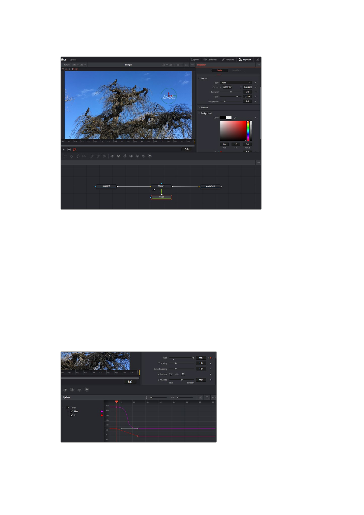
Selected nodes appear with a red border. Here the inspector
panel is displaying the layout tab controls for the text node.
There are different parameters and settings you can adjust for every node depending on its
task, from sizing and center positions to changing the number of particles in an emitter node.
Setting keyframes and changing the settings over time will animate the effect.
Working with Keyframes
In the inspector window, set a keyframe by right clicking on a setting and choosing ‘animate’
from the contextual menu. The keyframe icon to the right of the setting will turn red. This means
keyframes are now active and any changes you make will be applied to the current frame only.
When two or more keyframes are created by changing the setting parameters on a different
frame, a transition is interpolated between them. Arrows on each side of the keyframe icon let
you move the playhead to those exact positions on the timeline.
The splines panel gives you further control over keyframe animation. You can select keyframes,
such as the first and last, and smooth the animation between them into a bezier curve by typing
‘shift’ + ’s’, or right clicking on a keyframe and selecting ‘smooth’.
Here, the ‘size’ keyframe animation has been smoothed into a bezier
curve. You can click the bezier handles to shorten or lengthen the
curve, or the keyframe square icons to move the key frame location.
60Using DaVinci Resolve
Page 61
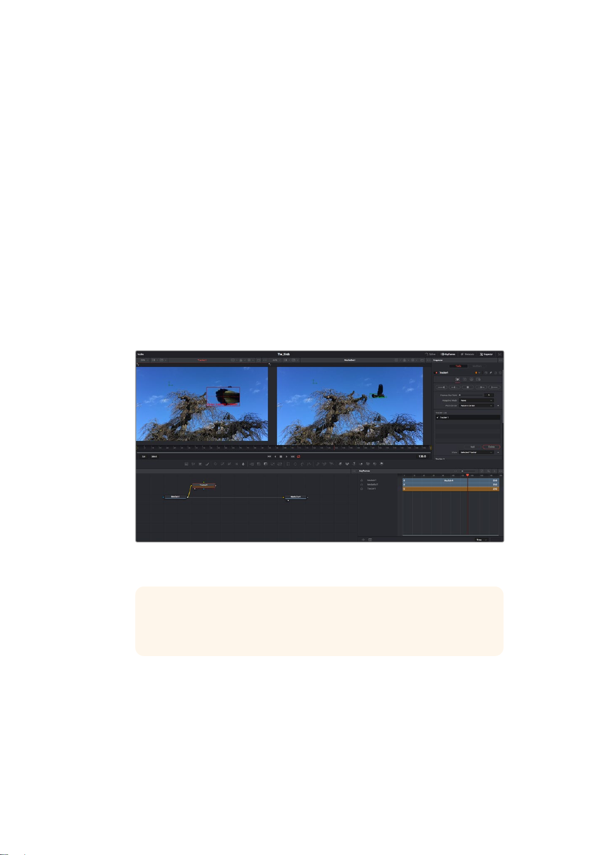
Using the Motion Tracker and Adding Text
To get a better idea of how to use Fusion, we have included the following examples to show
how to use the tracker tool to track an element in a clip, plus add text and attach it to the
element using the tracking data.
The ‘tracker’ tool tracks pixels over time on the x & y axis, and generates data you can use to
attach other elements. This is great for when you want to match the position of text to a moving
object, such as a car driving along the road, or a bird as it flies across frame.
1 In the ‘effects library’, select the ‘tracking’ tool and drag it to the line between the
‘mediain’ and the ‘mediaout’ nodes. Now click the tracker node to reveal its properties
in the inspector.
2 Type ‘1’ on your keyboard to see the ‘tracker’ node on the left viewer. The clip will
appear in the viewer together with the tracker at its default position. Hover your mouse
pointer over the tracker to reveal the tracker handle. Click on the tracker handle at the
top left corner and drag the tracker to an area of interest on your clip. High contrast
areas work well, for example the badge on the hood of a car. The tracker will magnify
the image area for extra precision.
3 In the inspector window, click on the ‘track forward’ button to start tracking.
A notification window will appear when the tracking is done. Click OK.
Tracking options in the inspector panel include track reverse from last frame or
current frame, stop track or track forward from current frame or first frame.
TIP Track reverse or forward from current frame is great for situations where
your area of interest disappears during the render range, such as a car or bird
moving out of frame. This lets you track only the relevant footage.
Now you can take that tracking data and apply the motion path to a text tool.
4 Click on the ‘text+’ node icon from the toolbar of commonly used nodes and drag it to
the node panel near the ‘tracker’ node. Connect the ‘text’ output square to the green
foreground input on the ‘tracker’.
61Using DaVinci Resolve
Page 62
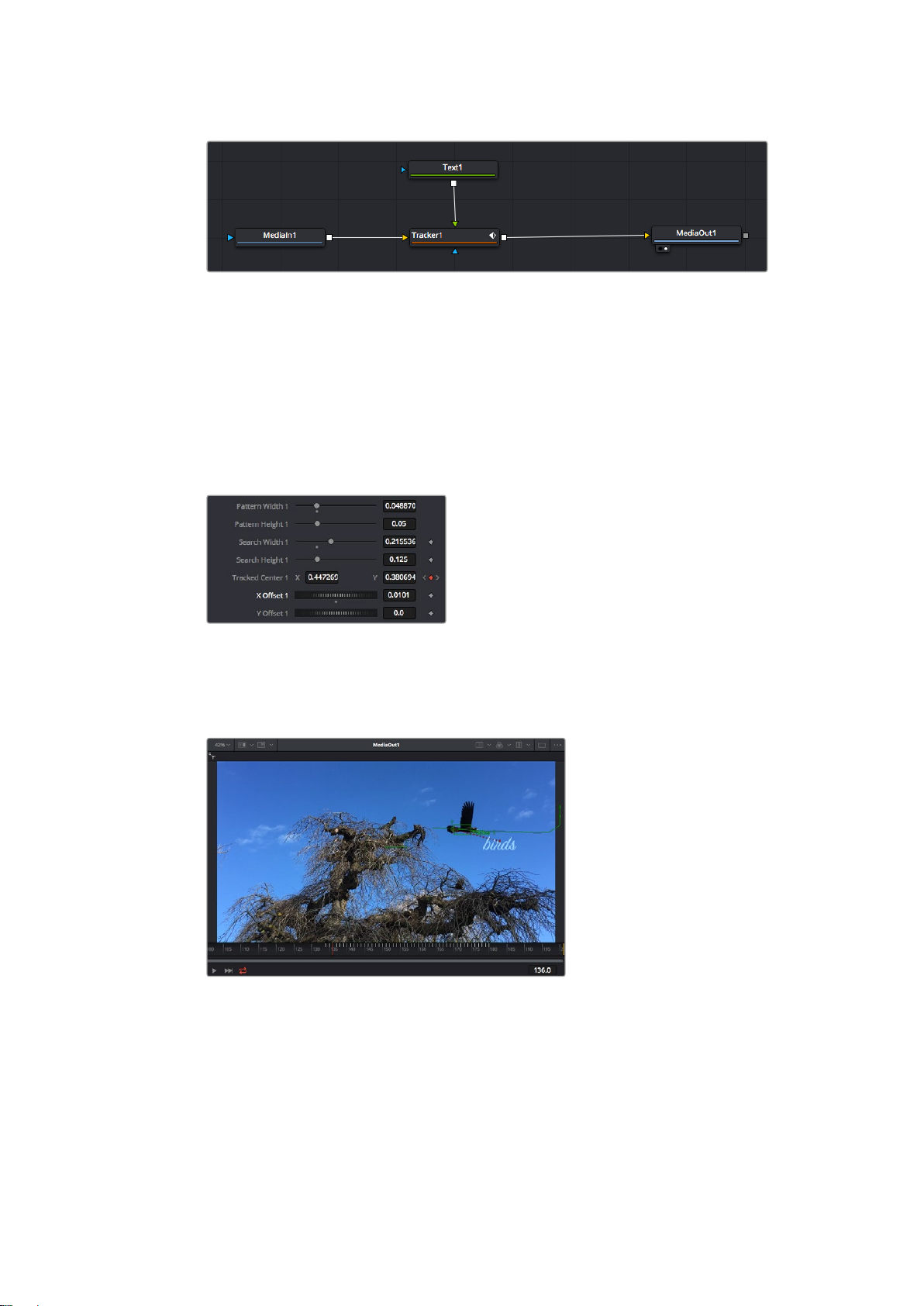
5 Click on the ‘tracker’ node and type ‘1’ so you can see the merged results on your left
hand viewer. In the ‘tracker’ inspector panel, click on the ‘operations’ tab. You can see
the tab’s name by hovering the mouse pointer over it. Click the dropdown menu next to
operation and select ‘match move’.
6 Click the ‘text’ node to reveal the properties in the inspector. Type your text into the
text box and change the font, color and size to suit your composition.
This will apply the tracking position data from your tracker to your text. If you want to
change the text offset, click on the ‘trackers’ tab back in the inspector panel and use
the x and y offset scroll wheels to modify the position.
Scroll wheels at the bottom of the tracker inspector
panelletyou adjust the offset position for the text.
Now you can play back your composition and see your text attached to the object you
have tracked!
The green square is the tracker’s current position along the green path,
and the red dashed line is the offset position used to animate the text.
For some shots you might want to remove track points after tracking, such as when the
object you are tracking disappears off the screen. The keyframe editor makes this a
very simple process.
62Using DaVinci Resolve
Page 63
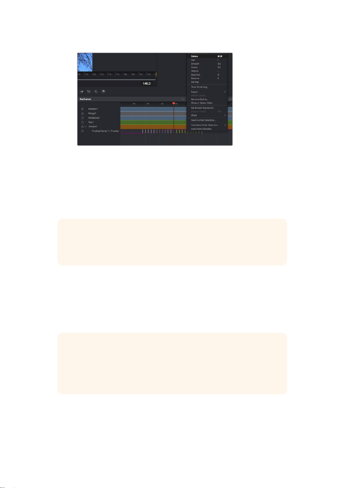
7 Click on the keyframes tab above the inspector to open the keyframes editor.
Any nodes with keyframes applied will have a small arrow next to the node label, and
only the parameter with keyframes added will appear in the list below. Click on the
magnify icon and drag a box around the area you want to edit. This will zoom into that
area so you can see the keyframes easier.
8 Move the playhead to the location of the last keyframe you want. Now select the
keyframes you wish to remove by drawing a box around them with your mouse.
The keyframes will highlight yellow. Right click and choose delete from the menu.
TIP If your effects are particularly system intensive, right clicking on the transport
controls area will give you viewer options, including proxy playback, helping you get
the most out of your system while you build your composition. Refer to the
DaVinci Resolve manual for further detail on all the playback options.
You have now completed your first composition animating text to match a movement in
your footage!
If you want to track an area of the image that contains a flat surface you want to enhance or
replace, you can use the planar tracker. Tracking 2D planes can be helpful for changing labels
and signs in a moving image, or even adding an image to a monitor or TV in your shot.
For more information about the planar tracker and the many powerful tools in the
DaVinci Resolve Fusion page, see the DaVinci Resolve manual.
TIP As you build visual effects in the Fusion page, it’s worth noting if the effect you are
building is a 2D effect, or a 3D effect, as this will determine which merge tool is used.
You may discover yourself frequently combining 2D and 3D effects in the one
composite. In this scenario, it’s helpful to remember that any visual effect using the
3D space needs to be rendered as a 2D image before it can be merged into a
2D composite.
We believe you will have lots of fun with Fusion and exploring Fusion’s visual effects with the
power of DaVinci Resolve’s edit, color, and Fairlight pages. With all these tools at your finger
tips, DaVinci Resolve is incredibly powerful and there is really no limit to what you can create!
63Using DaVinci Resolve
Page 64
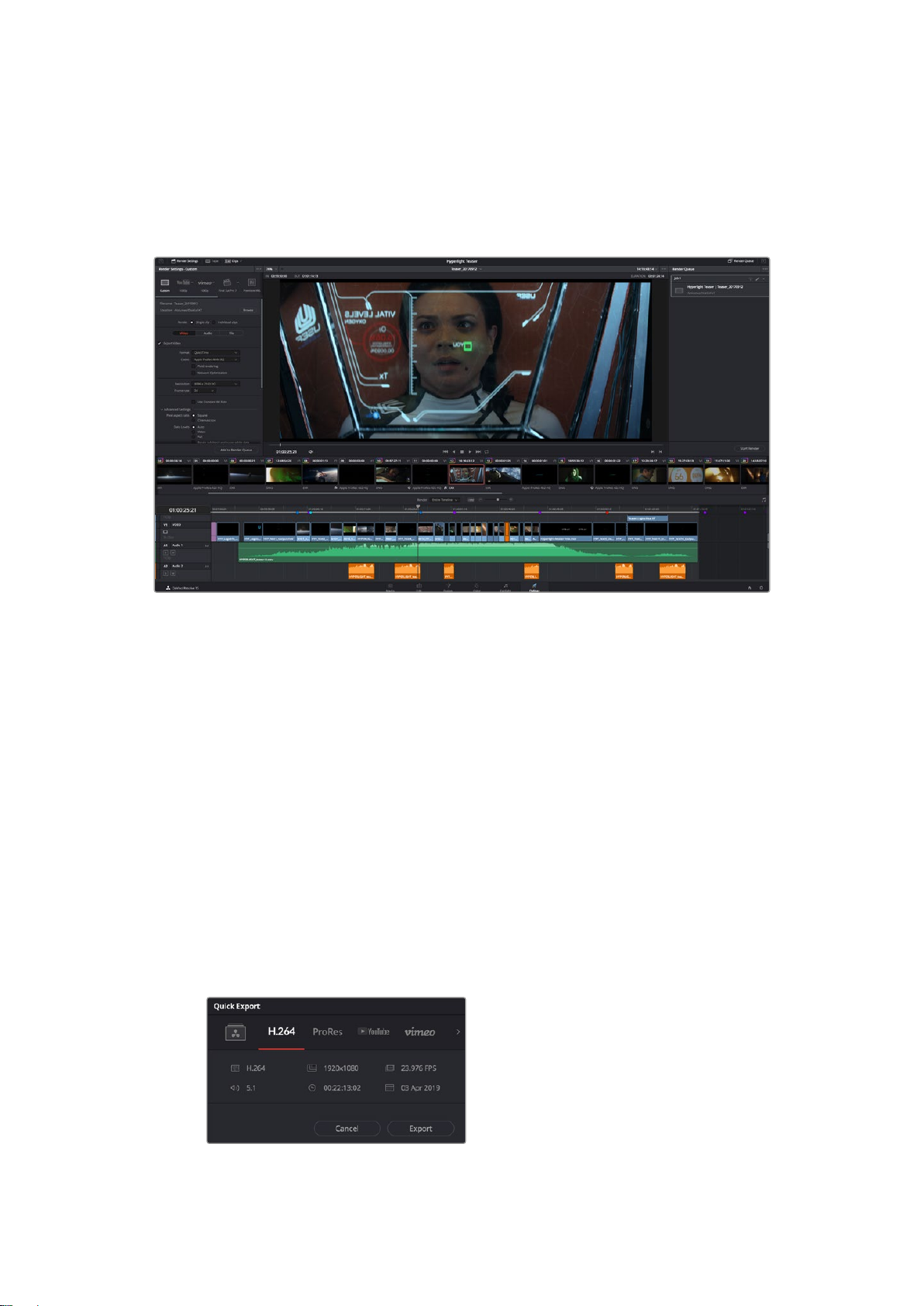
Mastering Your Edit
Now you’ve edited, graded, added vfx and mixed your audio, you’ll want to share it with others.
You can use the Quick Export button, or menu selection, to output the contents of the Timeline
as a self contained file in one of a variety of different formats, or use the additional features of
the ‘deliver’ page.
The ‘deliver’ page is where you export your edit. You can select from many different video formats and codecs
Quick Export
You can choose File > Quick Export to use one of a variety of export presets to export your
program from any page of DaVinci Resolve. You can even use quick export to export and
upload your program to one of the supported video sharing services, including YouTube,
Vimeo, and Frame.io.
To use Quick Export:
1 In the ‘edit’, ‘fusion’, or ‘color’ page, optionally set in and out points in the timeline to
choose a range of the current program to export. If no timeline in or out points have
been set, the entire timeline will be exported.
2 Choose File > Quick Export.
3 Select a preset to use from the top row of icons in the quick export dialog,
and click ‘export’.
4 Choose a directory location and enter a file name using the export dialog, then click
‘save’. A progress bar dialog appears to let you know how long the export will take.
The quick export dialog
64Using DaVinci Resolve
Page 65

The Deliver Page
This page lets you select the range of clips you want to export, plus the format, codec and
resolution you want. You can export in many types of formats such as QuickTime, AVI, MXF
and DPX using codecs such as 8-bit or 10-bit uncompressed RGB/YUV, ProRes, DNxHD, H.264
and more.
To export a single clip of your edit:
1 Click on the ‘deliver’ tab to open the deliver page.
2 Go to the ‘render settings’ window on the top left of the page. Choose from a number
of export presets, for example YouTube, Vimeo and audio presets, or you can set
your own export settings manually by leaving it set to the default ‘custom’ preset and
entering your own parameters. Forthis example, select YouTube, then click on the
arrow next to the preset and select the 1080p video format.
3 The frame rate will be locked to your project frame rate setting.
4 Underneath the presets you will see the timeline filename and the target location for
your exported video. Click the ‘browse’ button and choose the location where you want
to save your exported file and then select ‘single clip’ from the render option.
5 Immediately above the timeline, you’ll see an options box with ‘entire timeline’ selected.
This will export the entire timeline, however you can select a range of the timeline if
you want to. Simply choose ‘in/out range’ and then use the ‘i’ and ‘o’ hot key shortcuts
to choose the in and out points in your timeline.
6 Go to the bottom of the ‘render settings’ and click on the ‘add to render queue’ button.
Your render settings will be added to the render queue on the right side of the page.
Now all you have to do is click ‘start render’ and monitor the progress of your render in
the render queue.
When your render is complete you can open the folder location, double click on your
new rendered clip and watch your finished edit.
Now that you have a basic knowledge of how to edit, color, mix audio and add
visual effects, we recommend experimenting with DaVinci Resolve. Refer to the
DaVinci Resolve manual for more details on how each feature can help you make the
most of your project!
65Using DaVinci Resolve
Page 66
Developer Information
Blackmagic HyperDeck Ethernet Protocol
The Blackmagic HyperDeck Ethernet Protocol is a text based protocol accessed by connecting
to TCP port 9993 on HyperDeck Studio models that have a built in Ethernet connection. If you
are a software developer you can use the protocol to construct devices that integrate with our
products. Here at Blackmagic Design our approach is to open up our protocols and we eagerly
look forward to seeing what you come up with!
HyperDeck Studio recorders with SSD slots use version 1.8. HyperDeck Studio Mini uses 1.11.
Indented commands below are featured in version 1.11 only.
Protocol Commands
Command Command Description
help or ? Provides help text on all commands and parameters
commands return commands in XML format
device info return device information
disk list query clip list on active disk
disk list: slot id: {n} query clip list on disk in slot {n}
quit disconnect ethernet control
ping check device is responding
preview: enable: {true/false} switch to preview or output
play play from current timecode
play: speed: {-1600 to 1600} play at specific speed
play: speed: {-5000 to 5000} play at specific speed
play: loop: {true/false} play in loops or stop-at-end
play: single clip: {true/false} play current clip or all clips
playrange query playrange setting
playrange set: clip id: {n} set play range to play clip {n} only
playrange set: in: {inT} out: {outT}
playrange set: timeline in: {in} timeline
out: {out}
playrange clear clear/reset play range setting
play on startup query unit play on startup state
play on startup: enable: {true/false} enable or disable play on startup
play on startup: single clip: {true/false} play single clip or all clips on startup
play option query play options
play option: stop mode: {lastframe/
nextframe/black}
set play range to play between:
- timecode {inT} andtimecode {outT}
set play range in units of frames between:
- timeline position {in} and position {out} clear/reset play
rangesetting
set output frame when playback stops
66Developer Information
Page 67
Command Command Description
record record from current input
record: name: {name} record named clip
record spill spill current recording to next slot
record: spill: slot id: {n}
stop stop playback or recording
clips count query number of clips on timeline
clips get query all timeline clips
clips get: clip id: {n} query a timeline clip info
clips get: clip id: {n} count: {m} query m clips starting from n
clips get: version: {1/2}
clips add: name: {name} append a clip to timeline
clips add: clip id: {n} name: {name} insert clip before existing clip {n}
clips add: in: {inT} out: {outT} name:
{name}
clips remove: clip id: {n}
clips clear empty timeline clip list
transport info query current activity
slot info query active slot
slot info: slot id: {n} query slot {n}
slot select: slot id: {n} switch to specified slot
slot select: video format: {format} load clips of specified format
slot unblock unblock active slot
slot unblock: slot id: {n} unblock slot {n}
dynamic range
notify query notification status
notify: remote: {true/false} set remote notifications
notify: transport: {true/false} set transport notifications
notify: slot: {true/false} set slot notifications
notify: configuration: {true/false} set configuration notifications
notify: dropped frames: {true/false} set dropped frames notifications
notify: display timecode: {true/false} set display timecode notifications
notify: timeline position: {true/false} set playback timeline position notifications
notify: playrange: {true/false} set playrange notifications
spill current recording to specified slot
use current id to spill to same slot
query clip info using specified output version:
version 1: is: name startT duration
version 2: id: startT duration inT outT name
append the {inT} to {outT} portion of clip
remove clip {n} from the timeline
(invalidates clip ids following clip {n})
query dynamic range settings
dynamic range: playback override: {off/Rec709/Rec2020_
SDR/HLG/ST2084_300/ST2084_500/ST2084_800/
ST2084_1000/
ST2084_2000/ST2084_4000/ST2084
67Developer Information
Page 68

Command Command Description
notify: dynamic range: {true/false} set dynamic range settings notifications
goto: clip id: {start/end} goto first clip or last clip
goto: clip id: {n} goto clip id {n}
goto: clip id: +{n} go forward {n} clips
goto: clip id: -{n} go backward {n} clips
goto: clip: {n} goto frame position {n} within current clip
goto: clip: +{n} go forward {n} frames within current clip
goto: clip: -{n} go backward {n} frames within current clip
goto: clip: {start/end} goto start or end of clip
goto: timeline: {n} goto frame position {n} within timeline
goto: timeline: +{n} o forward {n} frames within timeline
goto: timeline: -{n} go backward {n} frames within timeline
goto: timeline: {start/end} goto start or end of timeline
goto: timecode: {timecode} goto specified timecode
goto: timecode: +{timecode} go forward {timecode} duration
goto: timecode: -{timecode} go backward {timecode} duration
goto: slot id: {n} goto slot id {n}
jog: timecode: {timecode} jog to timecode
jog: timecode: +{timecode} jog forward {timecode} duration
jog: timecode: -{timecode} jog backward {timecode} duration
shuttle: speed: {-1600 to 1600} shuttle with speed
shuttle: speed: {-5000 to 5000} shuttle with speed
remote query unit remote control state
remote: enable: {true/false} enable or disable remote control
remote: override: {true/false} session override remote control
configuration query configuration settings
configuration: video input: SDI switch to SDI input
configuration: video input: HDMI switch to HDMI input
configuration: video input: component switch to component input
configuration: audio input: embedded capture embedded audio
configuration: audio input: XLR capture XLR audio
configuration: audio input: RCA capture RCA audio
configuration: file format: {format} switch to specific file format
configuration: audio codec: PCM switch to PCM audio
configuration: audio codec: AAC switch to AAC audio
configuration: timecode input:
{external/embedded/preset/clip}
configuration: timecode preset:
{timecode}
change the timecode input
set the timecode preset
68Developer Information
Page 69
Command Command Description
configuration: audio input channels: {n} set the number of audio channels recorded to {n}
configuration: record trigger: {none/
recordbit/timecoderun}
configuration: record prefix: {name} set the record prefix name (supports UTF-8 name)
configuration: append timestamp:
{true/false}
uptime return time since last boot
format: prepare: {format} prepare a disk formatting operation to filesystem {format}
format: confirm: {token} perform a pre-prepared formatting operation using token
identify: enable: {true/false} identify the device
watchdog: period: {period in seconds} client connection timeout
change the record trigger
append timestamp to recorded filename
Command Combinations
You can combine the parameters into a single command, for example:
play: speed: 200 loop: true single clip: true
Or for configuration:
configuration: video input: SDI audio input: XLR
Or to switch to the second disk, but only play NTSC clips:
slot select: slot id: 2 video format: NTSC
Using XML
While you can use the Terminal to talk to HyperDeck, if you are writing software you can use
XML to confirm the existence of a specific command based on the firmware of the HyperDeck
you are communicating with. This helps your software user interface adjust to the capabilities of
the specific HyperDeck model and software version.
Protocol Details
Connection
The HyperDeck Ethernet server listens on TCP port 9993.
Basic syntax
The HyperDeck protocol is a line oriented text protocol. Lines from the server will be separated by an ascii
CR LF sequence. Messages from the client may be separated by LF or CR LF.
New lines are represented in this document as a "↵" symbol.
Command syntax
Command parameters are usually optional. A command with no parameters is terminated with a new line:
{Command name}↵
If parameters are specified, the command name is followed by a colon, then pairs of parameter names and
values. Each parameter name is terminated with a colon character:
{Command name}: {Parameter}: {Value} {Parameter}: {Value} ...↵
69Developer Information
Page 70

Response syntax
Simple responses from the server consist of a three digit response code and descriptive text terminated by
a new line:
{Response code} {Response text}↵
If a response carries parameters, the response text is terminated with a colon, and parameter name and
value pairs follow on subsequent lines until a blank line is returned:
{Response code} {Response text}:↵
{ P a r a m e t e r}: { Va l u e}↵
{ P a r a m e t e r}: { Va l u e}↵
...
↵
Successful response codes
A simple acknowledgement of a command is indicated with a response code of 200:
200 ok↵
Other successful responses carry parameters and are indicated with response codes in the range of 201 to
299.
Failure response codes
Failure responses to commands are indicated with response codes in the range of 100 to 199:
100 syntax error
101 unsupported parameter
102 invalid value
103 unsupported
104 disk full
105 no disk
106 disk error
107 timeline empty
108 internal error
109 out of range
110 no input
111 remote control disabled
120 connection rejected
150 invalid state
151 invalid codec
160 invalid format
161 invalid token
162 format not prepared
Asynchronous response codes
The server may return asynchronous messages at any time. These responses are indicated with response
codes in the range of 500 to 599:
5xx {Response Text}:↵
{ P a r a m e t e r}: { Va l u e}↵
{ P a r a m e t e r}: { Va l u e}↵
↵
70Developer Information
Page 71

Connection response
On connection, an asynchronous message will be delivered:
500 connection info:↵
protocol version: {Version}↵
model: {Model Name}↵
↵
Connection rejection
Only one client may connect to the server at a time. If other clients attempt to connect concurrently,
they will receive an error and be disconnected:
120 connection rejected↵
Timecode syntax
Timecodes are expressed as non-drop-frame timecode in the format:
HH:M M:SS:FF
Handling of deck "remote" state
The “remote” command may be used to enable or disable the remote control of the deck. Any attempt to
change the deck state over ethernet while remote access is disabled will generate an error:
111 remote control disabled↵
To enable or disable remote control:
remote: enable: {“true”, “false”} ↵
The current remote control state may be overridden allowing remote access over ethernet irrespective of
the current remote control state:
remote: override: {“true”, “false”} ↵
The override state is only valid for the currently connected ethernet client and only while the connection
remains open.
The “remote” command may be used to query the remote control state of the deck by specifying no
parameters:
remote↵
The deck will return the current remote control state:
210 remote info:↵
enabled: {“true”, “false”}↵
override: {“true”, “false”}↵
↵
Asynchronous remote control information change notification is disabled by default and may be
configured with the “notify” command. When enabled, changes in remote state will generate a “510 remote
info:”asynchronous message with the same parameters as the “210 remote info:” message.
Closing connection
The "quit" command instructs the server to cleanly shut down the connection:
quit↵
Checking connection status
The "ping" command has no function other than to determine if the server is responding:
ping↵
71Developer Information
Page 72

Getting help
The "help" or "?" commands return human readable help text describing all available commands and
parameters:
help↵
Or:
?↵
The server will respond with a list of all supported commands:
201 h e lp:↵
{Hel p T e x t}↵
{Hel p T e x t}↵
↵
Switching to preview mode
The "preview" command instructs the deck to switch between preview mode and output mode:
preview: enable: {"true", "false"}↵
Playback will be stopped when the deck is switched to preview mode. Capturing will be stopped when the
deck is switched to output mode.
Controlling device playback
The “play” command instructs the deck to start playing:
play↵
The play command accepts a number of parameters which may be used together in most combinations.
By default, the deck will play all remaining clips on the timeline then stop.
The “single clip” parameter may be used to override this behaviour:
play: single clip: {“true”, “false”}↵
By default, the deck will play at normal (100%) speed. An alternate speed may be specif ied in percentage
between -1600 and 1600:
play: speed: {% normal speed}↵
By default, the deck will stop playing when it reaches to the end of the timeline. The “loop” parameter may
be used to override this behaviour:
play: loop: {“true”, “false”}↵
The “playrange” command instructs the deck to play all the clips. To override this behaviour and select a
particular clip:
playrange set: clip id: {Clip ID}↵
To only play a certain timecode range:
playrange set: in: {in timecode} out: {out timecode}↵
To clear a set playrange and return to the default value:
playrange clear↵
The “play on startup command” instructs the deck on what action to take on startup. By default, the deck
will not play. Use the “enable” command to start playback after each power up.
play on startup: enable {“true”, “false”}↵
By default, the unit will play back all clips on startup. Use the “single clip” command to override.
play on startup: single clip: {“true”, “false”}↵
Stopping deck operation
The "stop" command instructs the deck to stop the current playback or capture:
stop↵
72Developer Information
Page 73

Changing timeline position
The "goto" command instructs the deck to switch to playback mode and change its position within the
timeline.
To go to the start of a specific clip:
goto: clip id: {Clip ID}↵
To move forward/back {count} clips from the current clip on the current timeline:
goto: clip id: +/-{count}↵
Note that if the resultant clip id goes beyond the first or last clip on timeline, it will be clamp at the first or
last clip.
To go to the start or end of the current clip:
goto: clip: {“start”, “end”}↵
To go to the start of the first clip or the end of the last clip:
goto: timeline: {“start”, “end”}↵
To go to a specified timecode:
goto: timecode: {timecode}↵
To move forward or back a specified duration in timecode:
goto: timecode: {“+”, “-”}{duration in timecode}↵
To specify between slot 1 and slot 2:
goto: slot id: {Slot ID}↵
Note that only one parameter/value pair is allowed for each goto command.
Enumerating supported commands and parameters
The "commands" command returns the supported commands:
commands↵
The command list is returned in a computer readable XML format:
212 commands:
<commands>↵
<command name="…"><parameter name="…"/>…</command>↵
<command name="…"><parameter name="…"/>…</command>↵
…
</commands>↵
↵
More XML tokens and parameters may be added in later releases.
Controlling asynchronous notifications
The “notify” command may be used to enable or disable asynchronous notifications from the server.
To enable or disable transport notifications:
notify: transport: {“true”, “false”}↵
To enable or disable slot notifications:
notify: slot: {“true”, “false”}↵
To enable or disable remote notifications:
notify: remote: {“true”, “false”}↵
To enable or disable configuration notifications:
notify: configuration: {“true”, “false”}↵
Multiple parameters may be specified. If no parameters are specified, the server returns the current state of
all notifications:
209 notify:↵
transport: {“true”, “false”}↵
slot: {“true”, “false”}↵
re mote: {“true”, “false”}↵
configuration: {“true”, “false”}↵
↵
73Developer Information
Page 74

Retrieving device information
The "device info" command returns information about the connected deck device:
device info↵
The server will respond with:
204 device info:↵
protocol version: {Version}↵
model: {Model Name}↵
unique id: {unique alphanumeric identifier}↵
↵
Retrieving slot information
The "slot info" command returns information about a slot. Without parameters, the command returns
information for the currently selected slot:
slot info↵
If a slot id is specified, that slot will be queried:
slot info: slot id: {Slot ID}↵
The server will respond with slot specif ic information:
202 slot info:↵
slot id: {Slot ID}↵
status: {"empty", "mounting", "error", "mounted"}↵
volu me name: {Volum e name}↵
recording time: {recording time available in seconds}↵
video format: {disk's default video format}↵
↵
Asynchronous slot information change notification is disabled by default and may be configured with
the "notify" command. When enabled, changes in slot state will generate a "502 slot info:" asynchronous
message with the same parameters as the "202 slot info:" message.
Retrieving clip information
The “disk list” command returns the information for each playable clip on a given disk. Without parameters,
the command returns information for the current active disk:
disk list↵
If a slot id is specified, the disk in that slot will be queried:
disk list: slot id: {Slot ID}↵
The server responds with the list of all playable clips on the disk in the format of: Index, name, formats, and
duration in timecode:
206 disk list:↵
slot id: {Slot ID}↵
{clip index}: {name} {file format} {video format} {Duration
tim e c o d e}↵
{clip index}: {name} {file format} {video format} {Duration
tim e c o d e}↵
…
↵
Note that the clip index starts from 1.
Retrieving clip count
The "clips count" command returns the number of clips on the current timeline:
clips count ↵
The server responds with the number of clips:
214 clips count: ↵
clip count: {Count}↵
74Developer Information
Page 75

Retrieving timeline information
The "clips get" command returns information for each available clip, for a given range in timecode,
on the current timeline. Without parameters, the command returns information for all clips on timeline:
clips get↵
The server responds with a list of clip IDs, names and timecodes:
205 clips info:↵
clip count: {Count}↵
{Clip ID}: {Name} {Start timecode} {Duration timecode}↵
{Clip ID}: {Name} {Start timecode} {Duration timecode}↵
…
↵
Note that the clip list format has changed incompatibly in protocol version 1.1,
i.e., Start timecode information field is inserted to each clip information line.
Retrieving transport information
The “transport info” command returns the state of the transport:
transport info ↵
The server responds with transport specific information:
208 transport info:↵
status: {“preview”, “stopped”, “play”, “forward”, “rewind”,
“j o g ”, “ s h u t t l e ”,” r e c o r d ”}↵
speed: {Play speed between -1600 and 1600 %}↵
slot id: {Slot ID or “none”}↵
display timecode: {timecode}↵
timecode: {timecode}↵
clip id: {Clip ID or “none”}↵
video format: {Video format}↵
loop: {“true”, “false”}↵
↵
The "timecode" value is the timecode within the current timeline for playback or the clip for record. The
"display timecode" is the timecode displayed on the front of the deck. The two timecodes will differ in some
deck modes.
Asynchronous transport information change notification is disabled by default and may be configured
with the "notify" command. When enabled, changes in transport state will generate a "508 transport info:"
asynchronous message with the same parameters as the "208 transport info:" message.
Video Formats
The following video formats are currently supported on HyperDeck Studio:
NTSC, PAL, NTSCp, PALp
720p50, 720p5994, 720p60
1080p23976, 1080p24, 1080p25, 1080p2997, 1080p30
1080i50, 1080i5994, 1080i60
HyperDeck Studio Pro adds supports for 4k formats:
4Kp23976, 4Kp24, 4Kp25, 4Kp2997, 4Kp30
HyperDeck Studio 12G adds support for the following 4k formats:
4Kp50, 4Kp5994, 4Kp60
Video format support may vary between models and software releases.
75Developer Information
Page 76

File Formats
All HyperDeck models currently support the following file formats:
QuickTimeUncompressed
QuickTimeProResHQ
QuickTimeProRes
QuickTimeProResLT
QuickTimeProResProxy
QuickTimeDNxHD220
DNxHD220
HyperDeck Studio Mini and HyperDeck Studio 12G additionally support the following file formats:
QuickTimeDNxHR_HQX
DNxHR_HQX
HyperDeck Studio Mini also supports the following file formats:
H.264Low
H.264Medium
H.264High
QuickTimeDNxHD45
DNxHD45
QuickTimeDNxHD145
DNxHD145
QuickTimeDNxHR_SQ
DNxHR_SQ
QuicktimeDNxHR_LB
DNxHR_LB
Supported file formats may vary between models and software releases.
Querying and updating configuration information
The "configuration" command may be used to query the current configuration of the deck:
configuration↵
The server returns the configuration of the deck:
211 configuration:↵
audio input: {“embedded”, “XLR”, “RCA”}↵
video input: {“SDI”, “HDMI”, “component”}↵
file format: {File format}↵
↵
One or more configuration parameters may be specified to change the configuration of the deck.
To change the current video input:
configuration: video input: {“SDI”, “HDMI”, “component”}↵
Valid video inputs may vary between models. To configure the current audio input:
configuration: audio input: {“embedded”, “XLR”, “RCA”}↵
Valid audio inputs may vary between models.
To configure the current file format:
configuration: file format: {File format}↵
Note that changes to the file format may require the deck to reset, which will cause the client connection to
be closed. In such case, response code 213 will be returned (instead of 200) before the client connection is
closed:
“213 deck rebooting”
Asynchronous configuration information change notification is disabled by default and may be configured
with the “notify” command. When enabled, changes in configuration will generate a “511 configuration:”
asynchronous message with the same parameters as the “211 configuration:” message.
76Developer Information
Page 77

Selecting active slot and video format
The "slot select" command instructs the deck to switch to a specified slot, or/and to select a specified
output video format.
To switch to a specified slot:
slot select: slot id: {slot ID}↵
To select the output video format:
slot select: video format: {video format}↵
Either or all slot select parameters may be specified. Note that selecting video format will result in a rescan
of the disk to reconstruct the timeline with all clips of the specified video format.
Clearing the current timeline
The "clips clear" command instructs the deck to empty the current timeline:
clips clear↵
The server responds with
200 ok↵
Adding a clip to the current timeline
The "clips add:" command instructs the deck to add a clip to the current timeline:
clips add: name: {"clip name"}↵
The server responds with
200 ok↵
or in case of error
1xx {error description}↵
Configuring the watchdog
The “watchdog” command instructs the deck to monitor the connected client and terminate the connection
if the client is inactive for at least a specified period of time.
To configure the watchdog:
watchdog: period: {period in seconds}↵
To avoid disconnection, the client must send a command to the server at least every {period} seconds. Note
that if the period is set to 0 or less than 0, connection monitoring will be disabled.
77Developer Information
Page 78

Help
Getting Help
The fastest way to obtain help is to go to the Blackmagic Design online support pages and
check the latest support material available for your Blackmagic HyperDeck Disk Recorder.
Blackmagic Design Online Support Pages
The latest manual, software and support notes can be found at the Blackmagic Design support
center at www.blackmagicdesign.com/support.
Blackmagic Design Forum
The Blackmagic Design forum on our website is a helpful resource you can visit for more
information and creative ideas. This can also be a faster way of getting help as there may
already be answers you can find from other experienced users and Blackmagic Design staff
which will keep you moving forward. You can visit the forum at https://forum.
blackmagicdesign.com
Contacting Blackmagic Design Support
If you can’t find the help you need in our support material or on the forum, please use the
“Sendus an email” button on the support page to email a support request. Alternatively,
click on the “Find your local support team” button on the support page and call your nearest
Blackmagic Design support office.
Checking the Software Version Currently Installed
To check which version of Blackmagic HyperDeck software is installed on your computer,
open the About Blackmagic HyperDeck Setup window.
On Mac OS, open Blackmagic HyperDeck Setup from the Applications folder.
Select About Blackmagic HyperDeck Setup from the application menu to reveal the
version number.
On Windows 7, open Blackmagic HyperDeck Setup from your Start menu. Clickon
the Help menu and select About Blackmagic HyperDeck Setup to reveal the
version number.
On Windows 8, open Blackmagic HyperDeck Setup from the Blackmagic HyperDeck
Setup tile on your Start page. Click on the Help menu and select About Blackmagic
HyperDeck Setup to reveal the version number.
How to Get the Latest Software Updates
After checking the version of Blackmagic HyperDeck Setup software installed on your computer,
please visit the Blackmagic Design support center at www.blackmagicdesign.com/support to
check for the latest updates. While it is usually a good idea to run the latest updates, it is wise to
avoid updating any software if you are in the middle of an important project.
78Help
Page 79
Regulatory Notices
Disposal of Waste of Electrical and Electronic Equipment Within the European Union.
The symbol on the product indicates that this equipment must not be disposed of with
other waste materials. In order to dispose of your waste equipment, it must be handed
over to a designated collection point for recycling. The separate collection and
recycling of your waste equipment at the time of disposal will help conserve natural
resources and ensure that it is recycled in a manner that protects human health and
theenvironment. For more information about where you can drop off your waste
equipment for recycling, please contact your local city recycling office or the dealer
from whom you purchased the product.
This equipment has been tested and found to comply with the limits for a Class A
digitaldevice, pursuant to Part 15 of the FCC rules. These limits are designed to provide
reasonable protection against harmful interference when the equipment is operated
inacommercial environment. This equipment generates, uses, and can radiate radio
frequency energy and, if not installed and used in accordance with the instructions,
maycause harmful interference to radio communications. Operation of this product in
aresidential area is likely to cause harmful interference, in which case the user will be
required to correct the interference at personal expense.
Operation is subject to the following two conditions:
1 This device may not cause harmful interference.
2 This device must accept any interference received, including interference that
may cause undesired operation.
KCC-REM-BMD-HDeckStudio
MSIP-REM-BMD-HDeckStudioPro
MSIP-REM-BMD-201509005
MSIP-REM-BMD-201702002
ISED Canada Statement
This device complies with Canadianstandards for Class A digital apparatus.
Any modifications or use of this product outside its intended use could void
compliance to these standards.
Connection to HDMI interfaces must be made with high quality shielded
HDMI cables.
This equipment has been tested for compliance with the intended use in a
commercial environment. If the equipment is used in a domestic environment,
it may cause radio interference.
79Regulatory Notices
Page 80
Safety Information
For protection against electric shock, the equipment must be connected to a mains socket
outlet with a protective earth connection. In case of doubt contact a qualifiedelectrician.
To reduce the risk of electric shock, do not expose this equipment to dripping orsplashing.
o
Product is suitable for use in tropical locations with an ambient temperature of up to 40
Ensure that adequate ventilation is provided around the product and that it is not restricted.
When rack mounting, ensure that the ventilation is not restricted by adjacent equipment.
No operator serviceable parts inside product. Refer servicing to your local Blackmagic Design
service center.
During sunny conditions, consider shading of the camera to prevent exposure of the camera
orlithium battery to extended periods of sunlight. Keep lithium batteries awayfrom all
sources of heat.
Some products have the facility to connect small form-factor transceiver (SFP) optical fibre
modules. Only use Laser class 1 optical SFP modules.
Recommended Blackmagic Design SFP modules:
ͽ 3G-SDI: PL-4F20-311C
ͽ 6G-SDI: PL-8F10-311C
ͽ 12G-SDI: PL-TG10-311C
C.
Use only at altitudes not more than 2000m above sea level.
State of California statement
This product can expose you to chemicals such as trace amounts of polybrominated biphenyls
within plastic parts, which is known to the state of California to cause cancer and birth defects
or other reproductive harm.
For more information go to www.P65Warnings.ca.gov.
Warning for Authorized Service Personnel
Disconnect power from both power inlets before servicing!
Caution - Double Pole/ Neutral Fusing
The power supply contained in this equipment has a fuse in both line and
neutral conductors and is suitable for connection to the IT power distribution
systemin Norway.
80Safety Information
Page 81

Warranty
12 Month Limited Warranty
Blackmagic Design warrants that this product will be free from defects in materials and workmanship
for a period of 12 months from the date of purchase. If a product proves to be defective during this
warranty period, Blackmagic Design, at its option, either will repair the defective product without
charge for parts and labor, or will provide a replacement in exchange for the defective product.
In order to obtain service under this warranty, you the Customer, must notify Blackmagic Design
of the defect before the expiration of the warranty period and make suitable arrangements for the
performance of service. The Customer shall be responsible for packaging and shipping the
defective product to a designated service center nominated by Blackmagic Design, withshipping
charges pre paid. Customer shall be responsible for paying all shipping charges, insurance, duties,
taxes, and any other charges for products returned to us for any reason.
This warranty shall not apply to any defect, failure or damage caused by improper use or improper
or inadequate maintenance and care. Blackmagic Design shall not be obligated to furnish service
under this warranty: a) to repair damage resulting from attempts by personnel other than
Blackmagic Design representatives to install, repair or service the product,
b) to repair damage resulting from improper use or connection to incompatible equipment,
c) to repair any damage or malfunction caused by the use of non Blackmagic Design parts or
supplies, or d) to service a product that has been modified or integrated with other products when
the effect of such a modification or integration increases the time or difficulty of servicing the
product. THIS WARRANTY IS GIVEN BY BLACKMAGIC DESIGN IN LIEU OF ANY OTHER
WARRANTIES, EXPRESS OR IMPLIED. BLACKMAGIC DESIGN AND ITS VENDORS DISCLAIM ANY
IMPLIED WARRANTIES OF MERCHANTABILITY OR FITNESS FOR A PARTICULAR PURPOSE.
BLACKMAGIC DESIGN’S RESPONSIBILITY TO REPAIR OR REPLACE DEFECTIVE PRODUCTS IS
THE WHOLE AND EXCLUSIVE REMEDY PROVIDED TO THE CUSTOMER FOR ANY INDIRECT,
SPECIAL, INCIDENTAL OR CONSEQUENTIAL DAMAGES IRRESPECTIVE OF WHETHER BLACKMAGIC
DESIGN OR THE VENDOR HAS ADVANCE NOTICE OF THE POSSIBILITY OF SUCH DAMAGES.
BLACKMAGIC DESIGN IS NOT LIABLE FOR ANY ILLEGAL USE OF EQUIPMENT BY CUSTOMER.
BLACKMAGIC IS NOT LIABLE FOR ANY DAMAGES RESULTING FROM USE OF THIS PRODUCT.
USER OPERATES THIS PRODUCT AT OWN RISK.
© Copyright 2020 Blackmagic Design. All rights reserved. ‘Blackmagic Design’, ‘DeckLink’, ‘HDLink’, ‘Workgroup Videohub’,
‘Multibridge Pro’, ‘Multibridge Extreme’, ‘Intensity’ and ‘Leading the creative video revolution’ are registered trademarks in the
US and other countries. All other company and product names may be trade marks of their respective companies with which
they are associated.
81Warranty
 Loading...