

Page 1
CAUTION
GENERAL
- Read all instructions carefully for safe operation and installation.
- All electrical connections must be in accordance with local and national electrical code (N.E.C) standards.
- Remove the fixture and the mounting package from the box and make sure that no parts are missing by
referencing the illustrations on the installation instruction. Please contact Blackjack Lighting if any parts
are missing or damaged.
- This product is suitable for damp locations.
INSTALLATION
PREPARATION
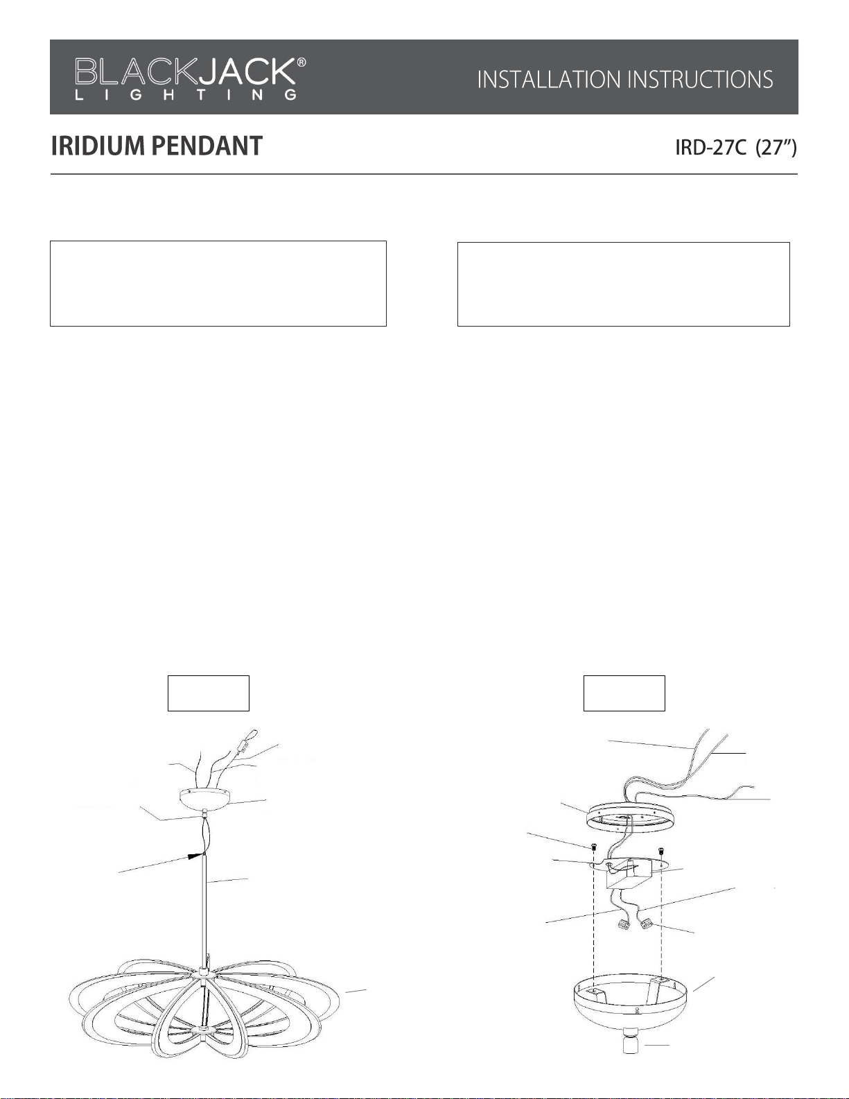
1. Remove the fixture from its box. You will see one 6” stem and three 12” stems(24). (This fixture can be ordered
with additional 24’’ stems if required). Each fixture provides a 12 foot wire length to accept up to 4 additional stem
sections (8 feet) for a maximum stem length of 11’6’’. Select the suitable size of stems and connect them to the desired
length you need to hang the fixture. Secure the stems to the threaded hang-straight(23) attached to the canopy. Pull the
fixture wire through the stems(24) and if necessary cut the excess wire.
2. Remove the wiring barrier plate(14) from the canopy cover(11) by loosening the two screws(26). (As shown in Fig.2)
TURN OFF THE MAIN POWER AT THE CIRCUIT
BREAKER BEFORE INSTALLING THE FIXTURE IN
ORDER TO PREVENT POSSIBLE SHOCK
IF YOU ARE UNFAMILIAR WITH PROPER
ELECTRICAL WIRING CONNECTIONS OBTAIN
THE SERVICES OF A QUALIFIED ELECTRICIAN
Figure 1.
Figure 2.
(20)
(17)
(11)
(15)
(23)
(25)
(24)
(2)
(4)
(10)
(6)
(26)
(14)
(16)
(18)
(19)
(27)
(13)
(11)
(23)
Page 2
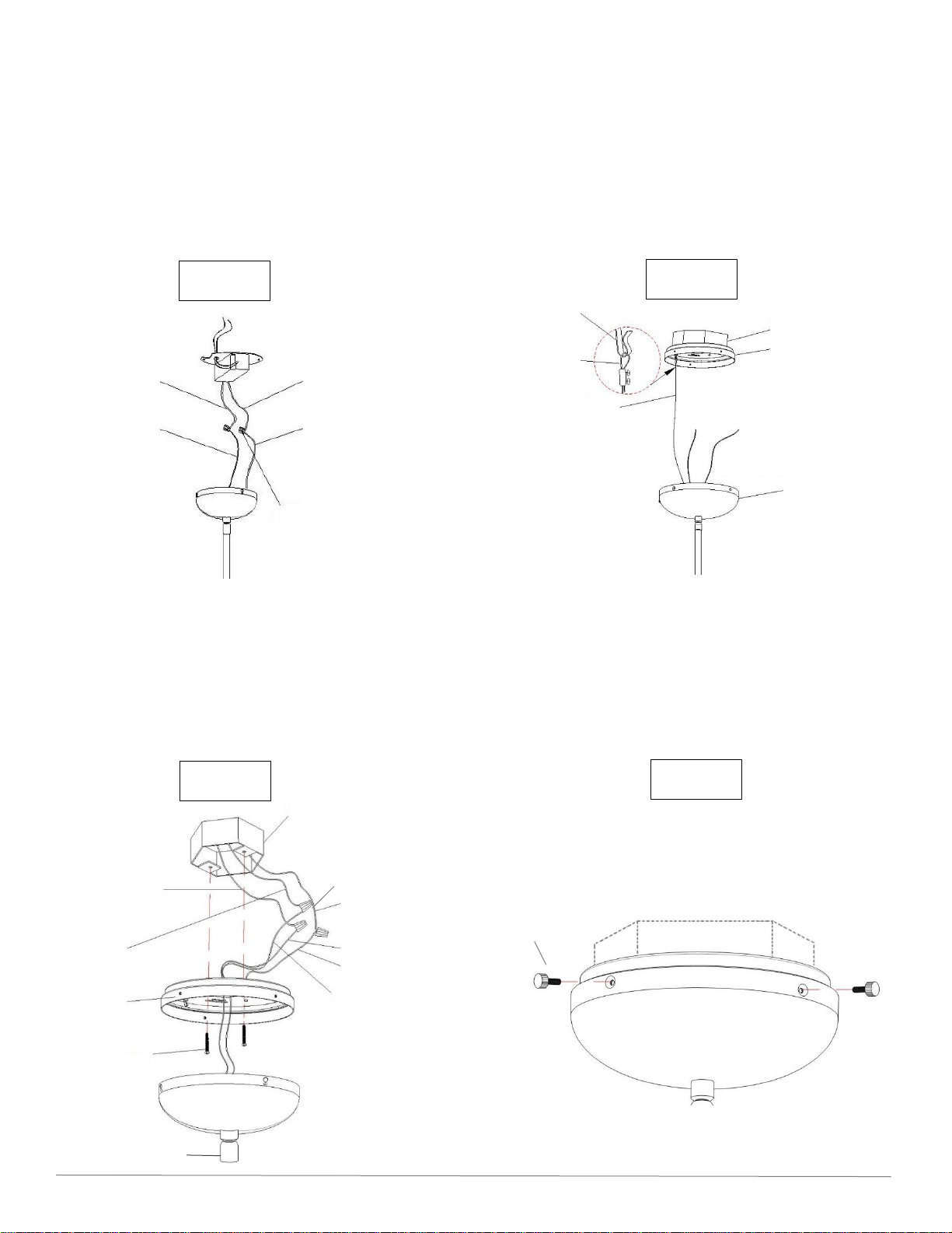
3. Insert the red+ fixture wire(15) into the quick connectors(19) at the end of driver red+ DC out wire(16); Insert the
black- fixture wire(17) into the quick connectors(19) at the end of driver black- DC out wire(18). Attach the wire barrier
plate(14) to the canopy cover(11) with the two screws(26).(As shown in Fig.3)
MOUNTING
4. Pull the white and black supply wires(2&4) and the house ground wire(6) out from the outlet box(1). Thread the wires
through the large center hole in the ceiling plate(10). Place the ceiling plate(10) over the outlet box(1). Insert the
mounting screws(9) through the slots on the ceiling plate(10). Then secure the mounting screws(9) into the outlet box(1)
tightly. (As shown in Fig.5)
5. To hang the fixture, use the lifting rope(20) as a support. Then attach the loop(22) on the lifting rope(20) to the
hook(21) secured on the ceiling plate(10). (As shown in Fig.4)
ELECTRICAL CONNECTIONS
6. Using the wire connectors(8), connect the white supply wire(2) from outlet box to the white fixture wire(3); connect
the black supply wire(4) to the black fixture wire(5). And connect the house ground wire(6) to the fixture ground wire(7).
Carefully tuck all wires back into the outlet box(1).
FINAL ASSEMBLY
7. Check all the wires after they are connected. To secure the canopy cover(11) to the ceiling plate(10) align the holes on
the side of the canopy cover(11) with the holes on the side of the ceiling plate(10). Insert and tighten the three
thumbscrews(12) to secure them together.(As shown in Fig.6)
BLACKJACK LIGHTING 1547 Barclay Blvd. Buffalo Grove, IL 60089 Blackjacklighting.com Tel: 847-941-0588
Figure 4.
Figure 3.
Figure 5.
Figure 6.
(16)
(15)
(18)
(17)
(19)
(2)
(1)
(4)
(10)
(9)
(6)
(3)
(7)
(5)
(8)
(21)
(22)
(20)
(1)
(10)
(11)
(12)
(23)
Page 3

DIMMING
- Fixture Dimming Type: TRIAC dimming
- For recommended dimmers see https://www.blackjacklighting.com/dimming-information
HARDWARE
Wire Connectors(#8) Mounting Screws(#9) Thumbscrews(#12) Quick Connectors(#19) Screws(#26)
[ 3 Included ] [ 2 Included ] [ 3 Included ] [ 2 Included ] [ 2 Included ]
BLACKJACK LIGHTING 1547 Barclay Blvd. Buffalo Grove, IL 60089 Blackjacklighting.com Tel: 847-941-0588
1. OUTLET BOX (by others)
2. WHITE SUPPLY WIRE
3. WHITE FIXTURE WIRE
4. BLACK SUPPLY WIRE
5. BLACK FIXTURE WIRE
6. HOUSING GROUND WIRE
7. FIXTURE GROUND WIRE
8. WIRE CONNECTORS
9. MOUNTING SCREWS
10. CEILING PLATE
11. CANOPY COVER
12. THUMBSCREWS
13. DRIVER
14. WIRE BARRIER PLATE
15. RED+ FIXTURE WIRE
16. RED+ DC OUT WIRE
17. BLACK- FIXTURE WIRE
18. BLACK- DC OUT WIRE
19. QUICK CONNECTORS
20. LIFTING ROPE
21. HOOK
22. LOOP
23. HANG STRAIGHT SWIVEL
24. STEM
25. 1/8” THREADED NIPPLE
26. SCREW
27. FIXTURE BODY
 Loading...