

Page 1
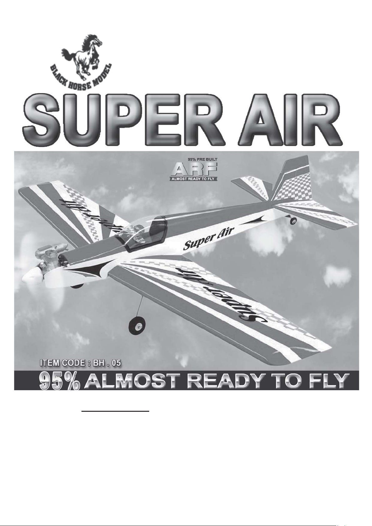
Instruction Manual book
SPECIFICATION
Wingspan : 1.550 mm 61.02 in.
Length : 1.250 mm 49.21 in.
Weight : 2.4 kg 5.28 Lbs.
Radio : 04 channels.
Servo : 05 servos.
Engine : 40 - 46 2 stroke
52 4 stroke
Made in Vietnam.
Page 2
SUPER AIR. Instruction Manual
This instruction manual is designed to help you build a great flying aeroplane. Please read this
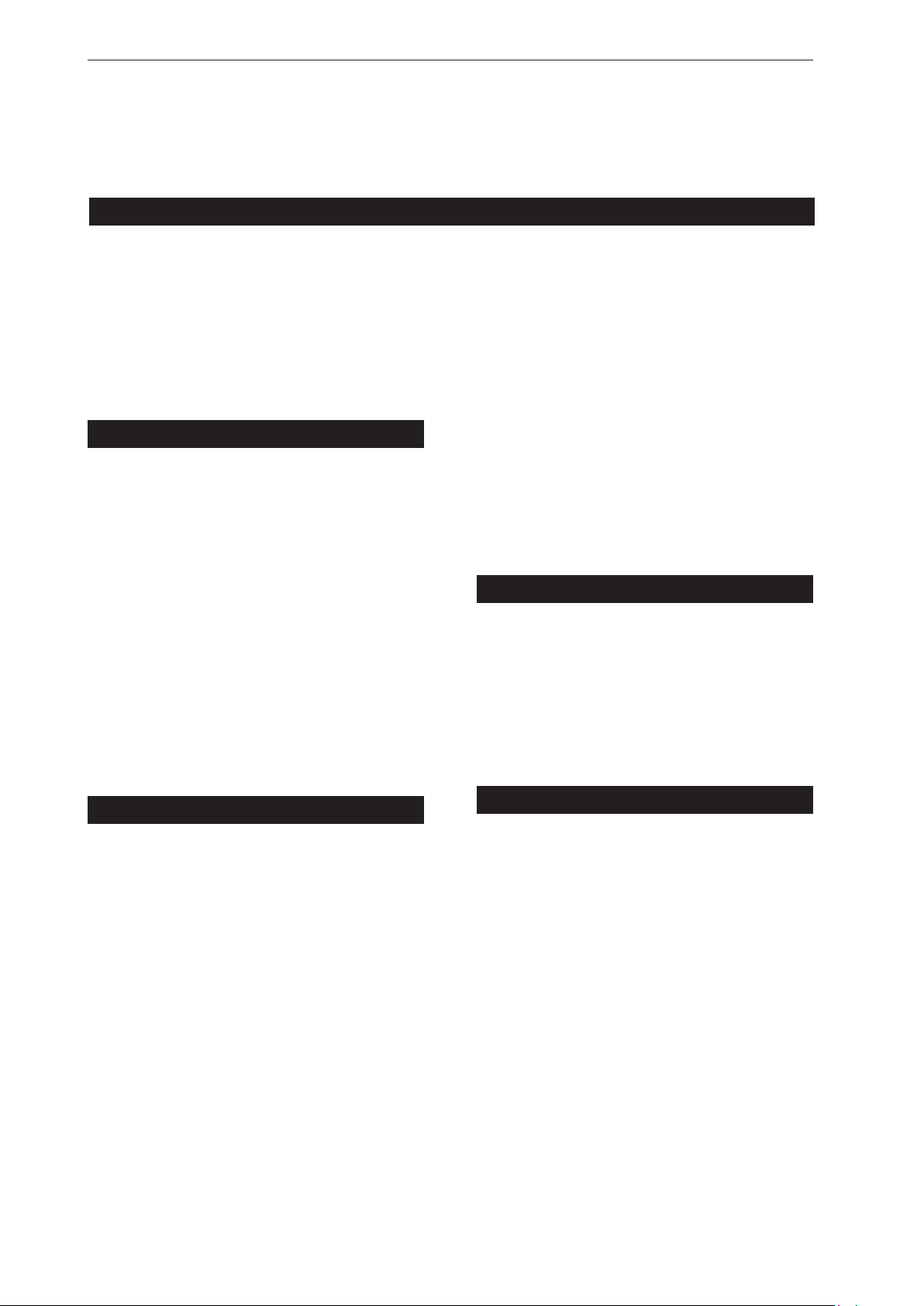
manual thoroughly before starting assembly of your SUPER AIR. Use the parts listing below to
identify all parts.
WARNING.
Please be aware that this aeroplane is not a toy and if assembled or used incorrectly it is
capable of causing injury to people or property. WHEN YOU FLY THIS AEROPLANE YOU
ASSUME ALL RISK & RESPONSIBILITY.
If you are inexperienced with basic R/C flight we strongly recommend you contact your R/C supplier
and join your local R/C Model Flying Club. R/C Model Flying Clubs offer a variety of training
procedures designed to help the new pilot on his way to successful R/C flight. They will also be able
to advise on any insurance and safety regulations that may apply.
TOOLS & SUPPLIES NEEDED.
Thick cyanoacrylate glue.
30 minute epoxy.
5 minute epoxy.
Hand or electric drill.
Assorted drill bits.
Modelling knife.
Straight edge ruler.
2mm ball driver.
Phillips head screwdriver.
220 grit sandpaper.
90° square or builder’s triangle.
Wire cutters.
Masking tape & T-pins.
Thread-lock.
Paper towels.
Some more parts.
HARDWARE PACK
Landing gear.....
SUGGESTION.
T o avoid scratching your new airplane, do not
unwrap the pieces until they are needed for
assembly. Cover your workbench with an old
towel or brown paper, both to protect the
aircraft and to protect the table. Keep a couple
of jars or bowls handy to hold the small parts
after you open the bag.
PARTS LISTING.
FUSELAGE ASSEMBLY
(1) Fuselage.
WING ASSEMBLY
(1) Right wing half with pre-installed
aileron.
(1) Left wing half with pre-installed
aileron.
Tail section assembly
(1) Vertical stabilizer with pre-
installed rudder.
(1) Horizontal stabilizer with pre-
installed elevator halves.
NOTE.
Please trial fit all the parts. Make sure you have
the correct parts and that they fit and are
aligned properly before gluing! This will assure
proper assembly.
made from natural materials, every plane is
unique and minor adjustments may have to
be made. However, you should find the fit
superior and assembly simple.
The painted and plastic parts used in this kit
are fuel proof. However, they are not tolerant
of many harsh chemicals including the
following: paint thinner, C/A glue accelerator,
C/A glue debonder and acetone. Do not let
these chemicals come in contact with the
colors on the covering and the plastic parts.
SUPER AIR ARF is hand
2
Page 3
SUPER AIR. INSTRUCTION MANUAL
SAFETY PRECAUTION.
+ This is not a toy
+ Be sure that no other flyers are using your
radio frequency .
+ Do not smoke near fuel
+ Store fuel in a cool, dry place, away from
children and pets.
+ Wear safety glasses.
+The glow plug clip must be securely attached
to the glow plug.
+ Do not flip the propeller with your fingers.
+ Keep loose clothing and wires away from
the propeller.
+ Do not start the engine if people are near.
Do not stand in line with the side of the
propeller.
+ Make engine adjustments from behind the
propeller only. Do not reach around the
spinning propeller.
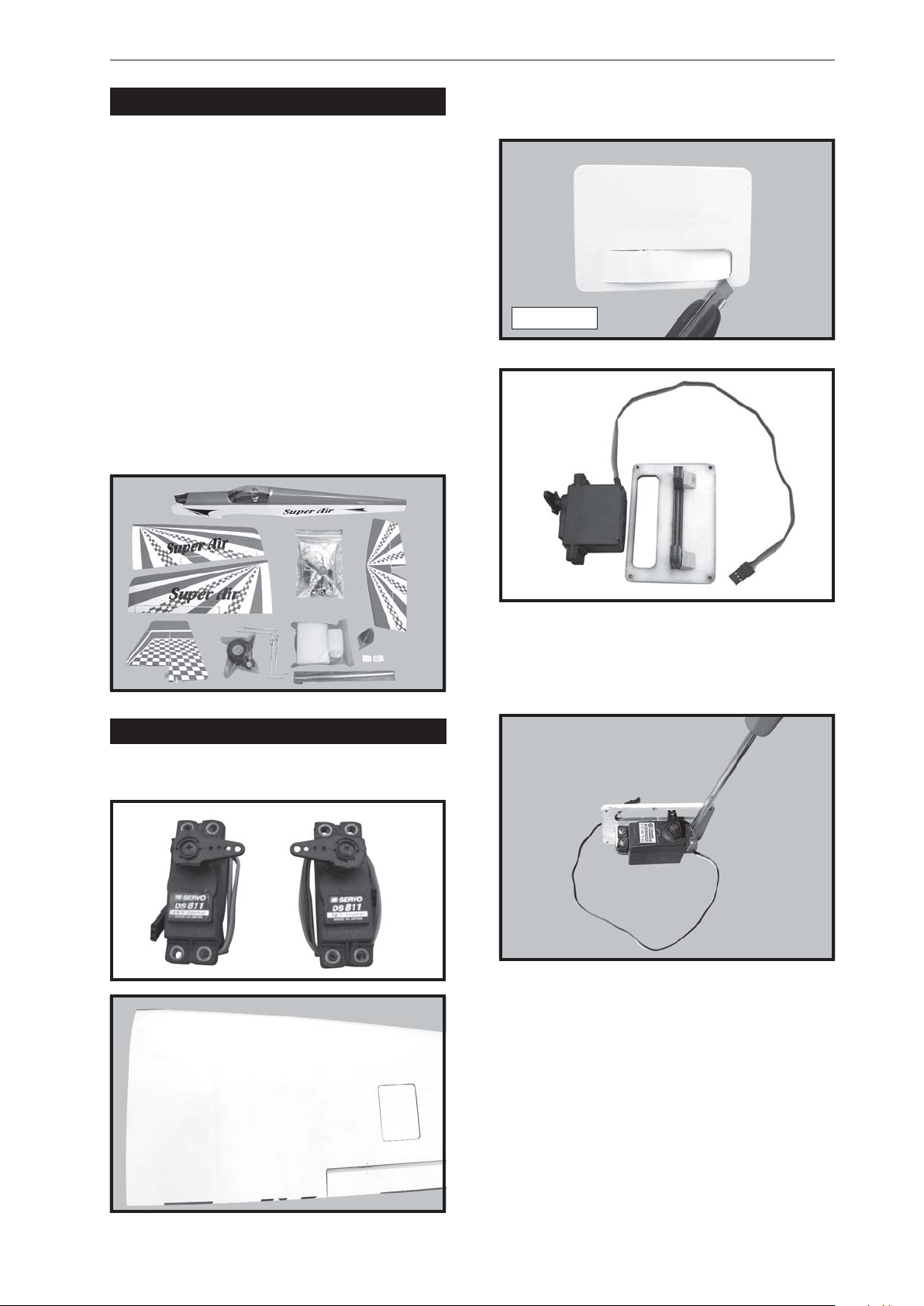
2. Using a modeling knife, remove the
covering servo tray .
Servo tray .
INSTALLING THE AILERON SERVOS.
1. Install the rubber grommets and brass
eyelets onto the aileron servo.
3. Drill 1,5mm pilot holes through the block
of wood for each of the four mounting screws
provided with the servo. Install servo into aileron
servo tray as same as picture below.
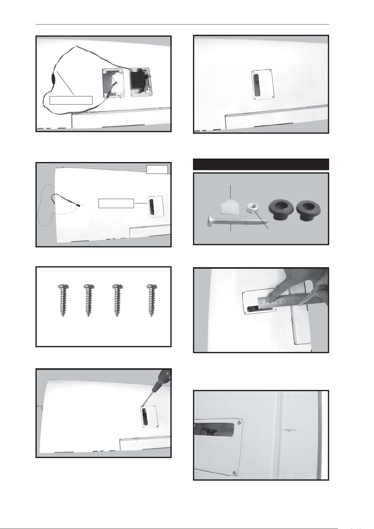
4. Using the thread as a guide and using
masking tape, tape the servo lead to the end
of the thread: carefully pull the thread out.
When you have pulled the servo lead out,
remove the masking tape and the servo lead
from the thread.
3
Page 4
SUPER AIR. Instruction Manual
Electric wire.
5. Instal servo tray with aileron servo into
the wing as same as picture below.
Wing.
Servo tray .
Repeat the procedure for the other wing
half.
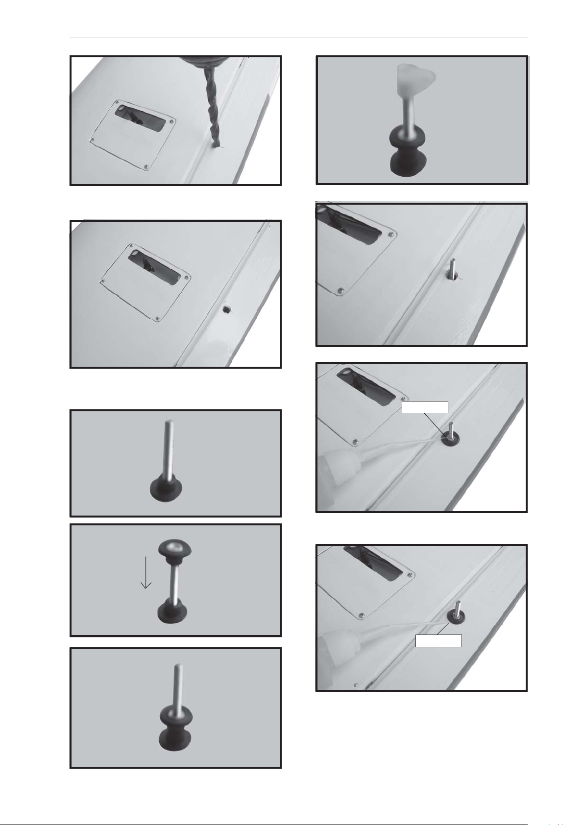
INST ALLING THE AILERON CONTROL HORN.
Nilon control clasp.
3x40mm.
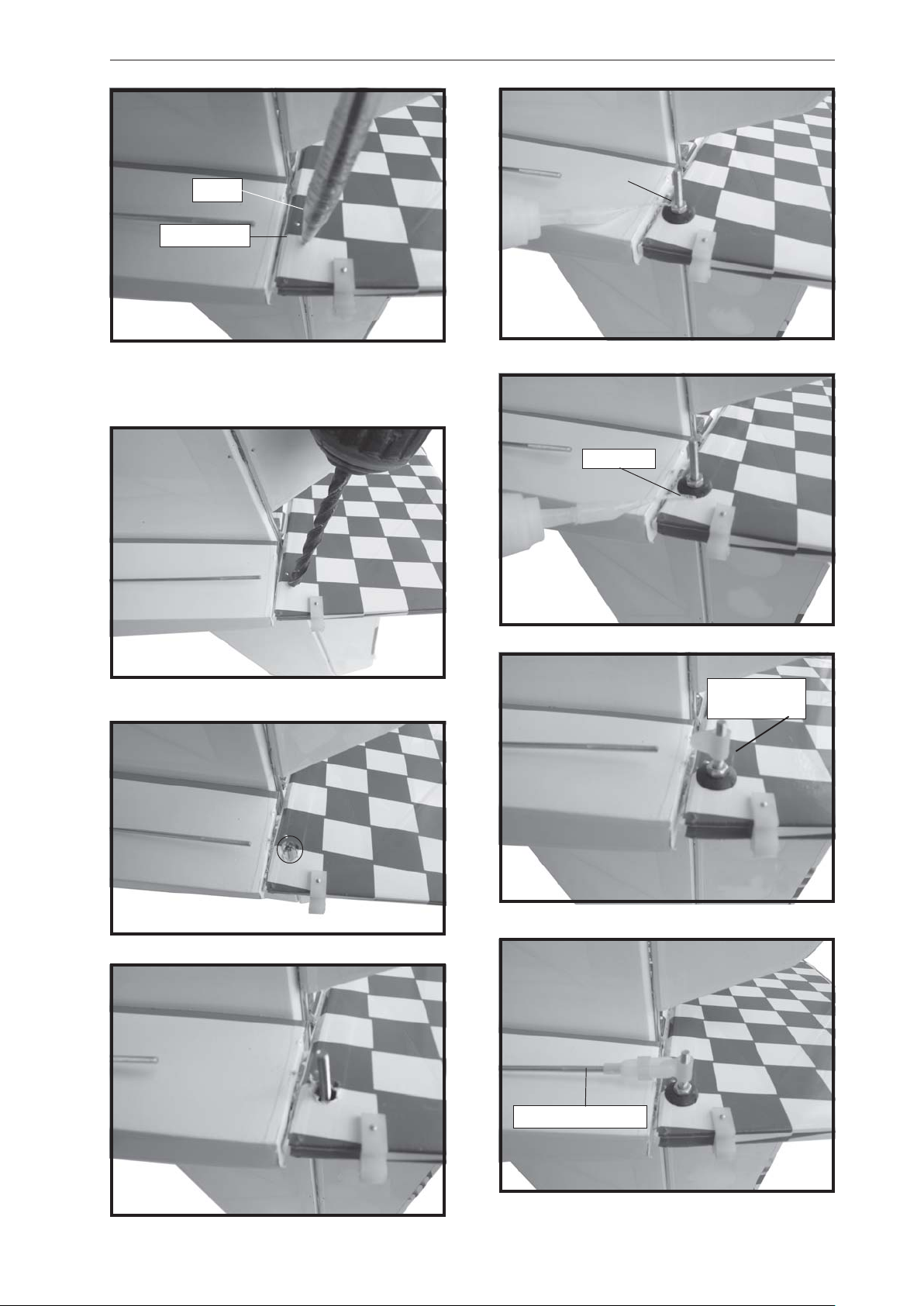
1. Using a ruler & pen to draw a straight
line as below picture.
M3 lock nut.
2x10mm.
2. Drill through 2mm (diameter) the aileron
using the control horn as a guide and screw
the control horn in place.
4
Page 5
SUPER AIR. INSTRUCTION MANUAL
Aileron control .
3. Install control horn as same as picture
below.
4. Install aileron control horn as same as
picture below.
C/A glue
C/A glue
5
Page 6
SUPER AIR. Instruction Manual
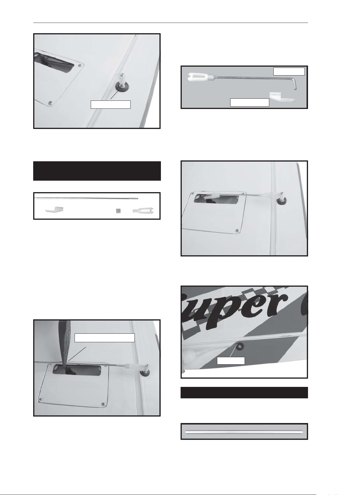
5. Using pliers, carefully make a 90 degree
bend down at the mark made. Cut off the
excess wire, leaving about 4mm beyond the
bend.
M2 clevis.
Control horn.
Bottom side.
Repeat the procedure for the other wing
half.
INSTALLING THE AILERON
LINKAGES.
1. Working with the aileron linkage for
now, thread one clevis onto one of the
threaded wires.
2. Attach the clevis to the outer hole in the
control horn. Install a silicone tube on the
clevis.
3. Plug the aileron servo into the receiver
and center the servo. Install the servo arm onto
the servo. The servo arm should be
perpendicular to the servo and point toward
the middle of the wing.
Snap keeper.
6. Insert the 90 degree bend down through
the hole in the servo arm. Install one nylon
snap keeper over the wire to secure it to the
arm. Install the servo arm retaining screw and
remove the masking tape from the aileron.
Bottom side.
Repeat the procedure for the other wing
half.
Bend and cut after.
4. Locate one nylon servo arm, and using
wire cutters,remove all but one of the arms.
Using a 2mm drill bit, enlarge the third hole
out from the center of the arm to accommodate
the aileron pushrod wire.
6
C/A glue
Top side.
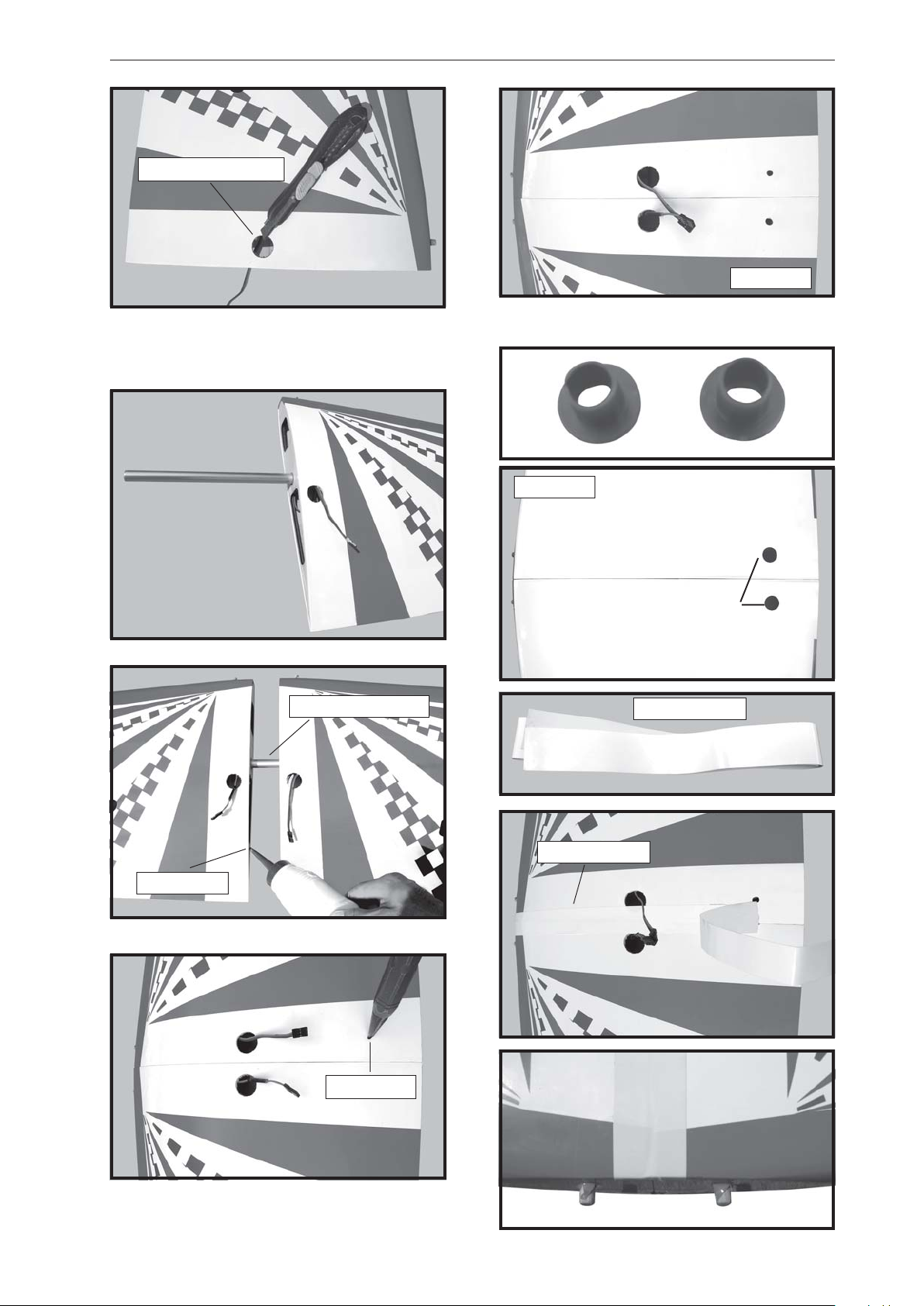
JOINING THE WING HALVES.
1. Locate the aluminium wing dihedral
brace.
2. Using a modeling knife, remove the
covering wing.
Page 7
SUPER AIR. INSTRUCTION MANUAL
Remove covering.
Top side.
Repeat the procedure for the other wing
3. Test fit the aluminium dihedral brace into
each wing half. The brace should slide in easily .
half.
Wing bolt
plate.
Top side.
Epoxy glue.
Aluminium brace.
Insert the wing bolt plate.
Masking tape.
Apply masking tape.
Masking tape.
Mark point.
7
Page 8
SUPER AIR. Instruction Manual
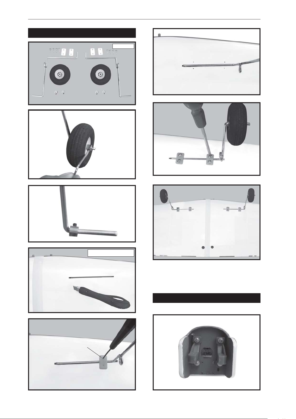
INST ALLING LANDING GEAR.
3x12mm.
1mm drill bit.
Remove covering.
Mark point.
INSTALLING THE ENGINE MOUNT.
8
Page 9
SUPER AIR. INSTRUCTION MANUAL
FUEL TANK.
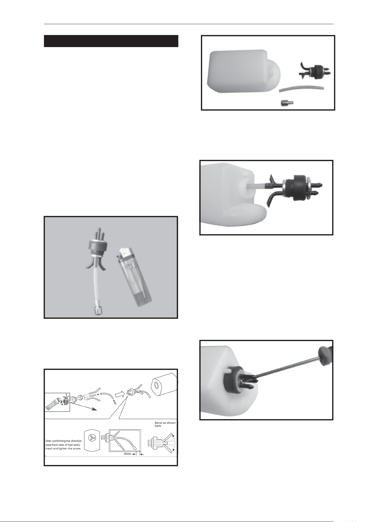
INSTALLING THE STOPPER ASSEMBLY
1. The stopper has been pre-assembled at
the factory .
2. Using a modeling knife, cut one length of
silicon fuel line (the length of silicon fuel line is
calculated by how the weighted clunk should
rest about 8mm away from the rear of the tank
and move freely inside the tank). Connect one
end of the line to the weighted clunk and the
other end to the nylon pick up tube in the
stopper.
3. Carefully bend the second nylon tube up
at a 45 degree angle (using a cigarette lighter).
This tube will be the vent tube to the muffler .
4. Carefully bend the third nylon tube down
at a 45 degree angle (using a cigarette lighter).
This tube will be vent tube to the fueling valve.
5. Test fit the stopper assembly into the
tank. It may be necessary to remove some of
the flashing around the tank opening using
a modeling knife. If flashing is present, make
sure none of it falls into the tank.
When the stopper assembly is installed
in the tank, the top of the vent tube should
rest just below the top surface of the tank.
It should not touch the top of the tank.
6. When satisfied with the alignment of the
stopper assembly tighten the 3mm x 20mm
machine screw until the rubber stopper
expands and seals the tank opening. Do not
over tighten the assembly as this could cause
the tank to split.
7. Using a modeling knife, cut 3 lengths of
fuel line 150mm long. Connect 2 lines to the 2
vent tubes and 1 line to the fuel pickup tube in
the stopper.
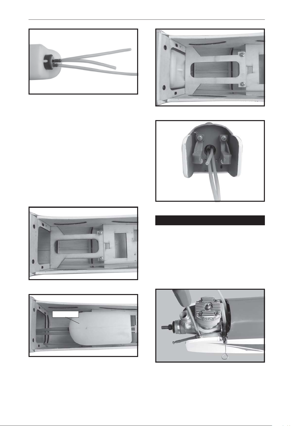
8. Feed three lines through the fuel tank
compartment and through the pre-drilled hole
in the firewall. Pull the lines out from behind
the engine, while guiding the fuel tank into
place. Push the fuel tank as far forward as
possible, the front of the tank should just about
touch the back of the firewall.
9
Page 10
SUPER AIR. Instruction Manual
Blow through one of the lines to ensure
the fuel lines have not become kinked inside
the fuel tank compartment. Air should flow
through easily .
9. To secure the fuel tank in place, apply a
bead of silicon sealer to the forward area of
the tank, where it exits the fuselage behind the
engine mounting box and to the rear of the tank
at the forward bulkhead.
Do not secure the tank into place
permanently until after balancing the
airplane. You may need to remove the tank
to mount the battery in the fuel tank
compartment.
Fuel tank.
INSTALLING THE ENGINE.
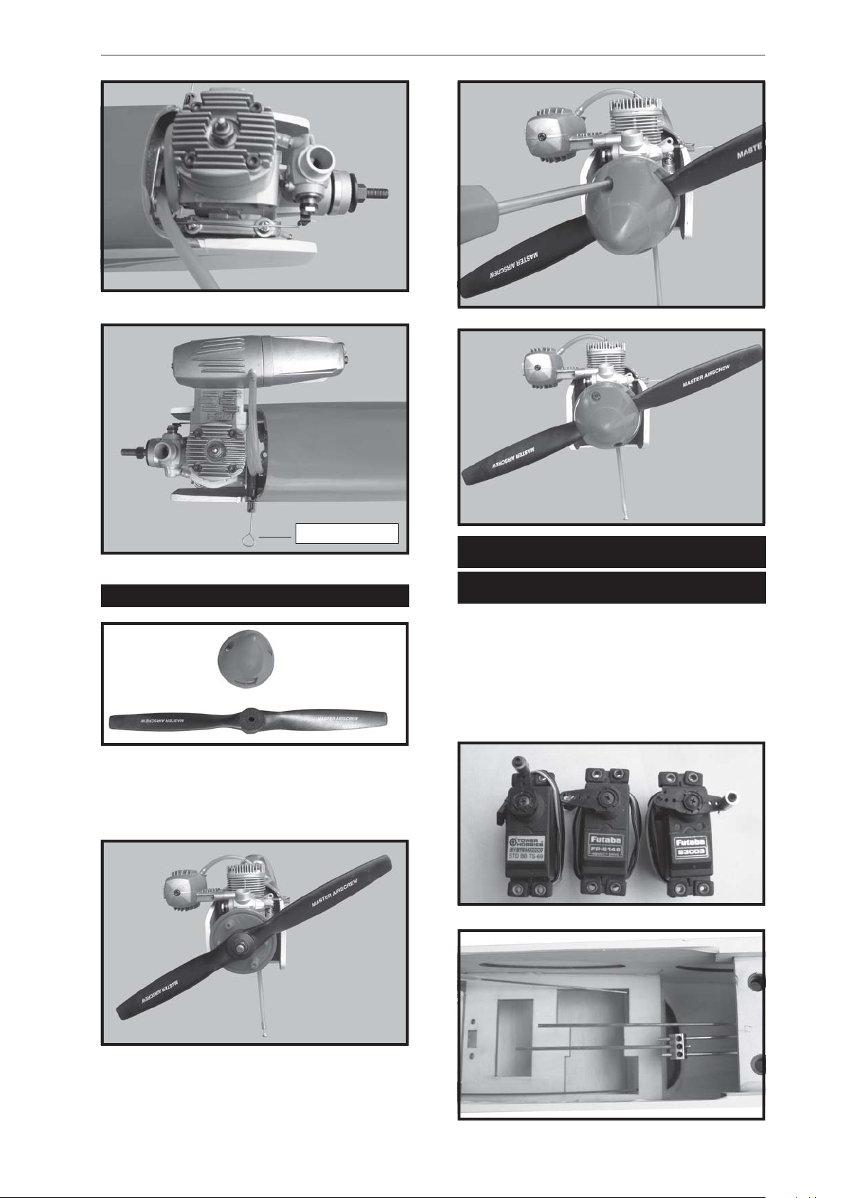
Locate the long piece of wire used for the
throttle pushrod. One end of the wire has been
pre-bend in to a “Z” bend at the factory. This
“Z” bend should be inserted into the throttle
arm of the engine when the engine is fitted onto
the engine mount. Fit the engine to the engine
mount using the screws provided.
10
Page 11
SUPER AIR. INSTRUCTION MANUAL
Throttle wire.
INSTALLING THE SPINNER.
Install the spinner backplate, propeller and
spinner cone. The spinner cone is held in
place using two 3mm x 12mm wood screws.
ELEVATOR INSTALLATION.
SERVO INSTALLATION.
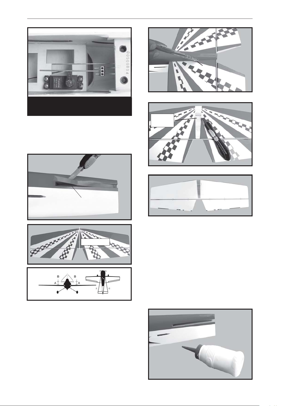
1. Install the rubber grommets and brass
collets into the elevator servo. Test fit the servo
into the servo tray .
2. Mount the servo to the tray using the
mounting screws provided with your radio
system.
11
Page 12
SUPER AIR. Instruction Manual
Elevator servo.
Pen.
HORIZONTAL STABILIZER
INSTALLATION.
1. Using a modeling knife, cut away the
covering from the fuselage for the stabilizer
and remove it.
2. Draw a center line onto the horizontal
stabilizer. Then slide the horizontal into the
fuselage.
Remove
covering.
Remove covering.
Center line.
Top side
Bottom side
5. When you are sure that everything is
aligned correctly, mix up a generous amount
of 30 minute epoxy. Apply a thin layer to the
top and bottom of the stabilizer mounting area
and to the stabilizer mounting platform sides
in the fuselage. Slide the stabilizer in place and
re-align. Double check all of your
measurements one more time before the
epoxy cures. Remove any excess epoxy using
a paper towel and rubbing alcohol and hold
the stabilizer in place with T-pins or masking
tape.
3. Mark the shape of the vertical on the left
and right sides onto the horizontal stabilizer
using a felt-tip pen
4. Remove the stabilizer. Using the lines
you just drew as a guide, carefully remove the
covering from between them using a modeling
knife.
When cutting through the covering to
remove it, cut with only enough pressure
to only cut through the covering it’s self.
Cutting into the balsa structure may
weaken it. This could lead to possible
failure during flight
12
Page 13
SUPER AIR. INSTRUCTION MANUAL
6. After the epoxy has fully cured, re-
move
the masking tape or T -pins used to hold the
stabilizer in place and carefully inspect the
glue joints. Use more epoxy to fill in any
gaps that were not filled previously and
clean up the excess using a paper towel and
rubbing alcohol.
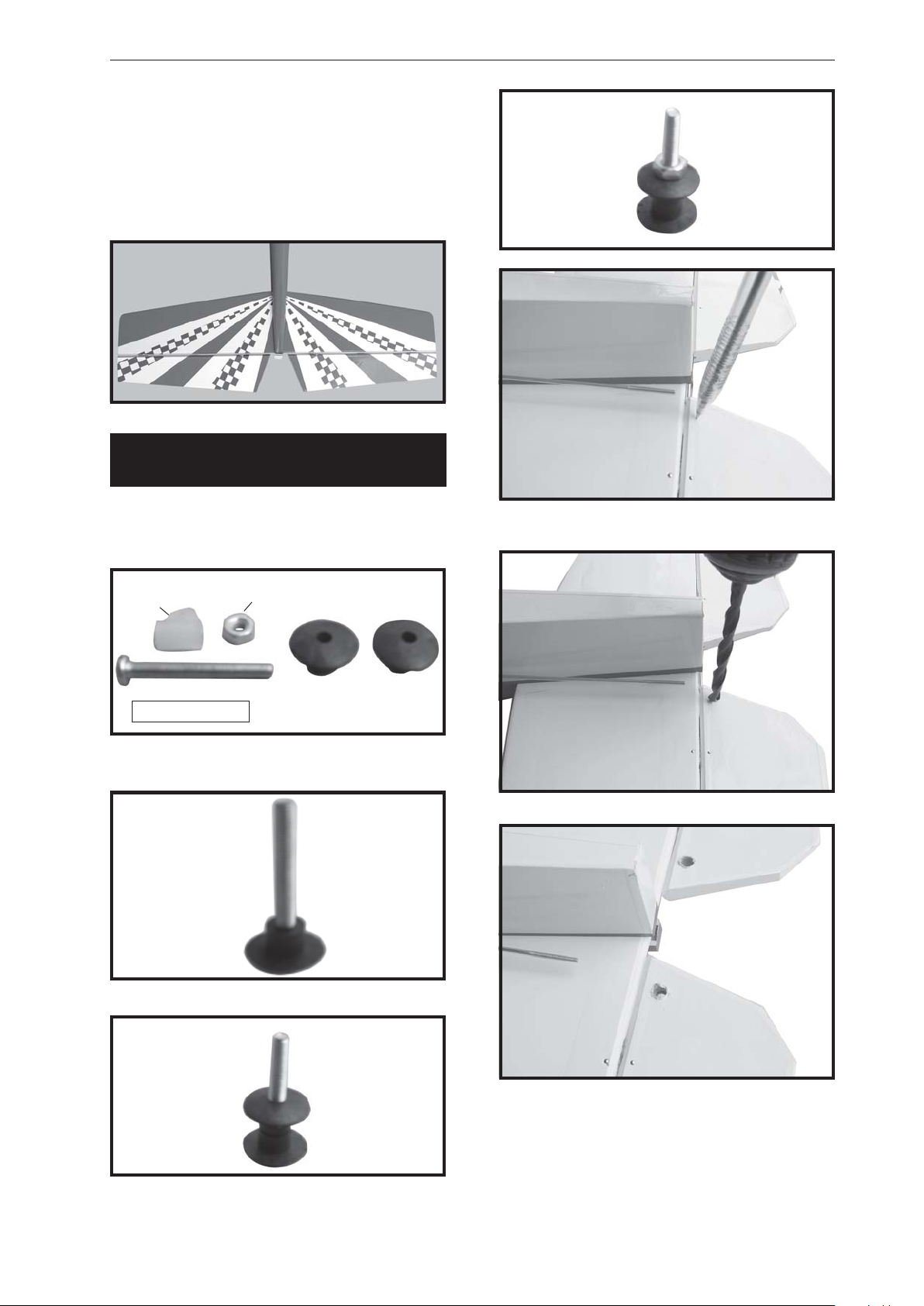
ELEVATOR CONTROL HORN
INSTALLATION.
Elevator control horn install as same as the
way of aileron control horn. Please see pictures
below.
Nilon
control clasp.
3mm x 40mm.
Control horn of elevator.
M3 lock nut.
Mark point
Drill 1 hole with 6 mm diameter.
13
Page 14
SUPER AIR. Instruction Manual
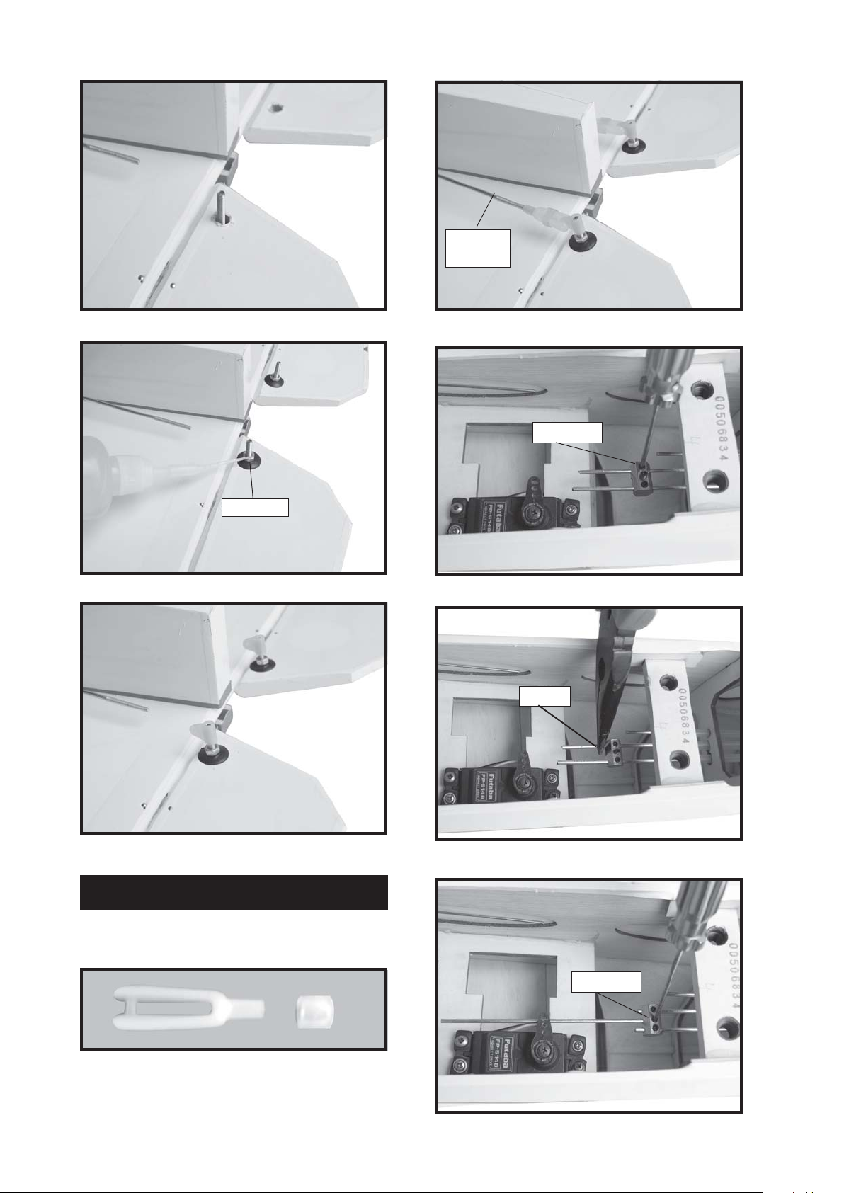
Elevator
pushrod.
Secure.
C/A glue
ELEVATOR PUSHROD INSTALLATION.
Cut.
Elevator pushrod install as same as the way
of aileron pushrod.
14
Secure.
Page 15
SUPER AIR. INSTRUCTION MANUAL
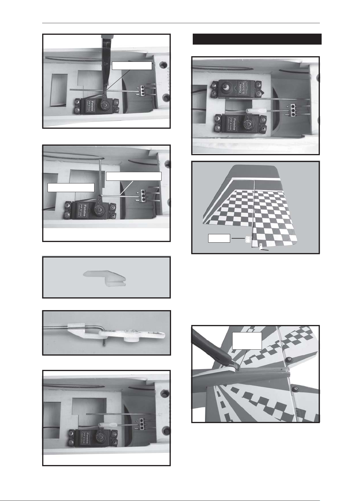
VERTICAL INSTALLATION.
Ben and cut.
Elevator pushrod.
Elevator servo.
Hinge.
Control clasp.
1) Using a modeling knife, remove the
covering from the top of the fuselage and the
covering from over the precut hinge slot cut
into the lower rear portion of the fuselage This
slot accepts the lower vertical.
2. Slide the rudder into the fuselage as
same as picture below.
Remove
covering.
15
Page 16
SUPER AIR. Instruction Manual
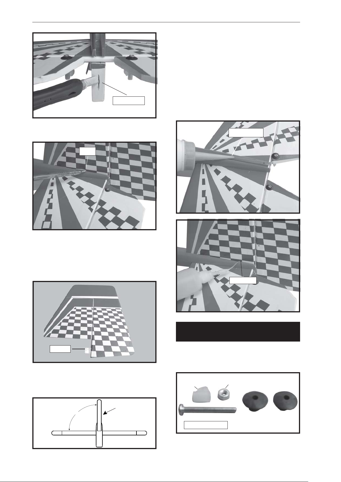
6) When you are sure that everything is a
aligned correctly, mix up a generous amount
of 30 minute epoxy. Apply a thin layer to the
slot in the mounting platform and to the vertical
stabilizer mounting area. Apply epoxy to the
lower rudder hinge. Set the stabilizer in place
and re-align. Double check all of your
measurements once more before the epoxy
cures. Remove any excess epoxy using a
Hinge slot.
3. Mark the shape of the vertical on the left
and right side on the rudder using a felt-tip
pen.
Pen.
paper towel and rubbing alcohol and hold the
stabilizer in place with T -pins or masking tape.
Allow the epoxy to fully cure before proceeding.
Epoxy glue.
4. Now, remove the rudder and using a
modeling knife, carefully cut just inside the
marked lines and remove the film of the rudder .
Just as you did with the horizontal stabilizer,
make sure you only press hard enough to cut
the film, not the balsa rudder.
Hinge.
5. Put the vertical stabilizer back in
place. Using a triangle, check to ensure
that the vertical stabilizer is aligned 90 degree
to the horizontal stabilizer.
C/A glue
RUDDER CONTROL HORN
INSTALLATION.
Rudder control horn install as same as the
way of aileron control horn. Please see pictures
below.
Nilon
control clasp.
M3 lock nut.
Horizontal
St abilizer.
16
Vertical
90º
St abilizer.
3mm x 40mm.
Control horn of Rudder .
Page 17
SUPER AIR. INSTRUCTION MANUAL
C/A glue
Pen.
Mark point.
Drill 6mm diameter a hole of the mounting
rudder control horn on to the rudder .
C/A glue
Rudder pushrod.
Rudder
control horn.
17
Page 18
SUPER AIR. Instruction Manual
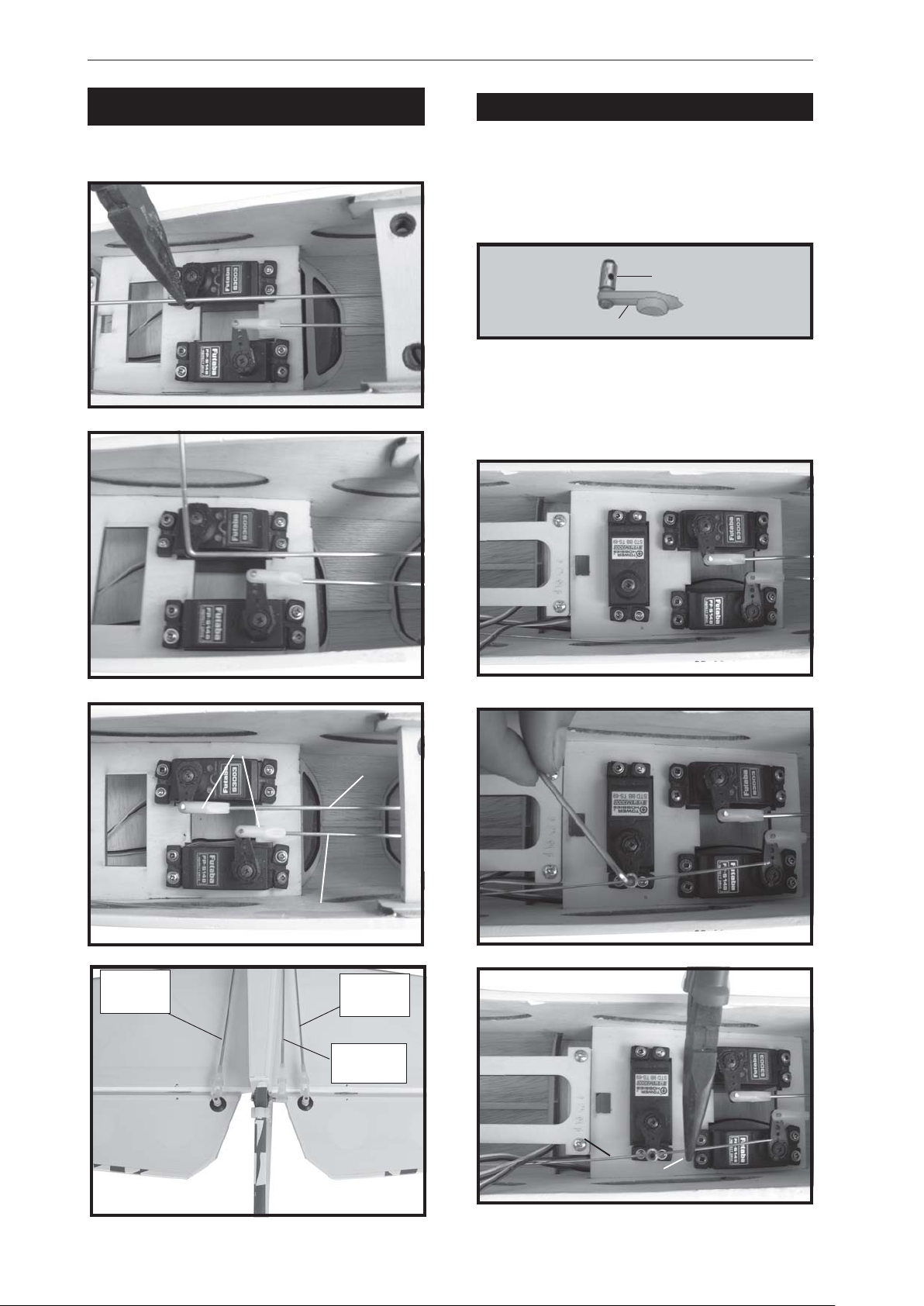
RUDDER PUSHROD INSTALLATION.
Rudder pushrod install as same as the way
of aileron pushrod.
Bend and cut
after
INST ALLING THE THROTTLE PUSHROD.
1. Install one adjustable metal connector
through the third hole out from the center of
one servo arm, enlarge the hole in the servo
arm using a 2mm drill bit to accommodate the
servo connector. Remove the excess material
from the arm.
Connector.
Servo arm.
After installing the adjustable metal
connector apply a small drop of thin C/A
to the bottom nut. This will prevent the
connector from loosening during flight.
Throttle servo.
Elevator
pushrod.
Snap keeper.
Rudder pushrod.
Secure
Elevator pushrod.
Elevator
pushrod.
Rudder
pushrod.
Throttle pushrod.
Cut.
18
Page 19
SUPER AIR. INSTRUCTION MANUAL
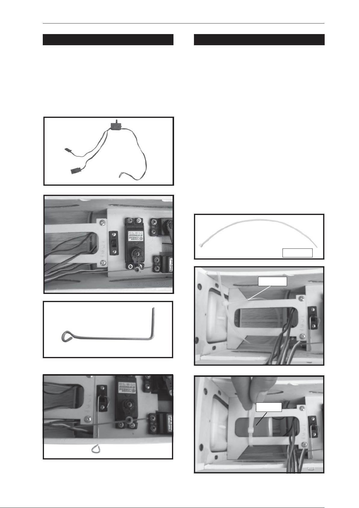
INSTALLING THE SWITCH.
1. Cut out the switch hole using a modeling
knife. Use a 2mm drill bit and drill out the two
mounting holes through the fuselage side.
2. Secure the switch in place using the
two machine screws provided with the radio
system.
INST ALLING THE RECEIVER AND BA TTERY.
1. Plug the servo leads and the switch
lead into the receiver. Y ou may want to plug
an aileron extension into the receiver to make
plugging in the aileron servo lead easier
when you are installing the wing . Plug the
battery pack lead into the switch.
2. Wrap the receiver and battery pack in
the protective foam to protect them from
vibration. Use a rubber band or masking tape
to hold the foam in place.
3. Position the battery pack and receiver
behind the fuel tank. Use two tie wraps to hold
the battery and receiver securely in place as
pictures below
Do not permanently secure the receiver and
battery until after balancing the model.
Tie wrap.
Battery.
Tie wrap.
19
Page 20
SUPER AIR. Instruction Manual
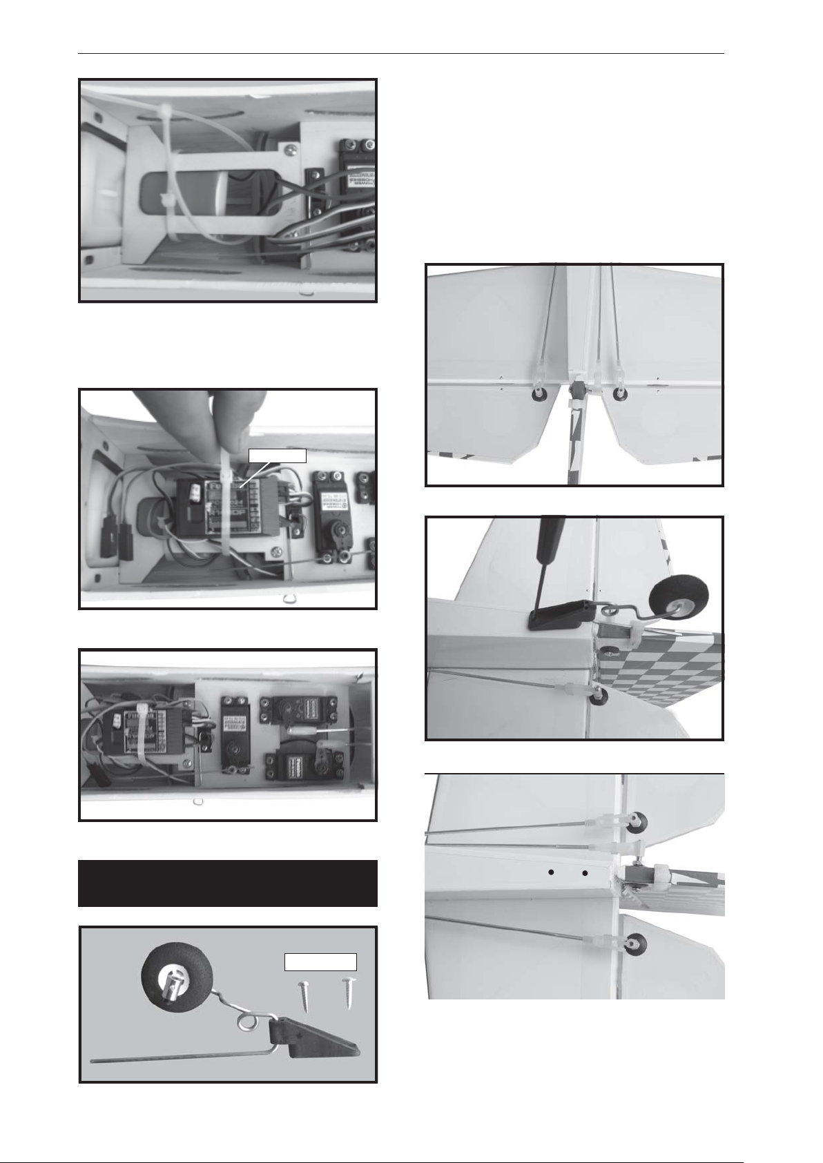
1. Set the tail wheel assembly in place
on the plywood plate. The pivot point of the
tail wheel wire should be even with the rudder hinge line and the tail wheel bracket should
be centered on the plywood plate.
2. Using a pen, mark the locations of the
two mounting screws. Remove the tail wheel
bracket and drill 1mm pilot holes at the locations marked.
4. Using a 2mm drill bit, drill a hole through
the side of the fuselage, near the receiver, for
the antenna to exit.
Receiver.
MOUNTING THE TAIL WHEEL
BRACKET.
20
3x12mm.
3. Secure the tail wheel bracket in place
using three 3mm x 12mm wood screws. Be
careful not to overtighten the screws.
Page 21
SUPER AIR. INSTRUCTION MANUAL
BALANCING.
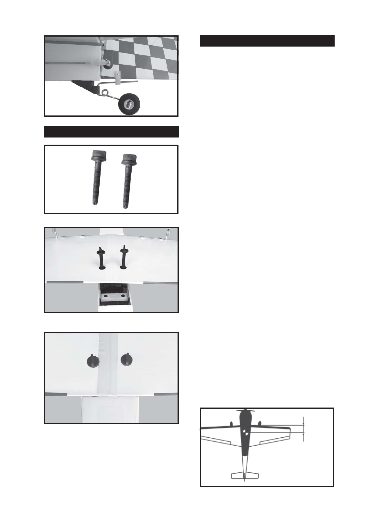
1) It is critical that your airplane be balanced
correctly. Improper balance will cause your
plane to lose control and crash.
THE CENTER OF GRAVITY IS LOCATED
100mm BACK FROM THE LEADING EDGE
OF THE WING .
2) Mount the wing to the fuselage. Using a
couple of pieces of masking tape, place them
WING A TT ACHMENT .
wing bolt.
Secure
on the top side of the wing 100 mm back from
the leading edge, at the fuselage sides.
3. Turn the airplane upside down. Place
your fingers on the masking tape and carefully
lift the plane .
Accurately mark the balance point on the top
of the wing on both sides of the fuselage. The
balance point is located 100mm back from the
leading edge. This is the balance point at which
your model should balance for your first flights.
Later, you may wish to experiment by shifting
the balance up to 10mm forward or back to
change the flying characteristics. Moving the
balance forward may improve the
smoothness and arrow- like tracking, but it may
then require more speed for take off and make
it more difficult to slow down for landing.
Moving the balance aft makes the model more
agile with a lighter and snappier ”feel”. In any
case, please start at the location we
recommend .
finishing.
With the wing attached to the fuselage, all
parts of the model installed ( ready to fly), and
empty fuel tanks, hold the model at the
marked balance point with the stabilizer level.
Lift the model. If the tail drops when you
lift, the model is “tail heavy” and you must add
weigh* to the nose. If the nose drops, it is “nose
heavy” and you must add weight* to the tail to
balance.
*If possible, first attempt to balance the model
by changing the position of the receiver
battery and receiver. If you are unable to obt ain
good balance by doing so, then it will be
necessary to add weight to the nose or tail to
achieve the proper balance point.
CG
100 MM
21
Page 22
SUPER AIR. Instruction Manual
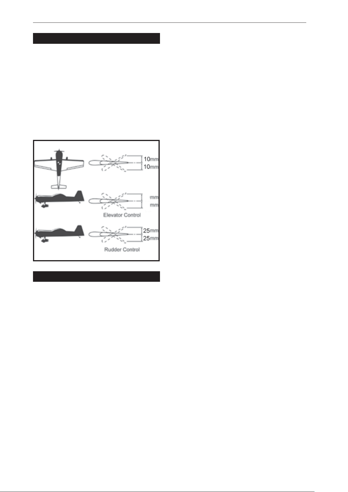
CONTROL THROWS.
1. We highly recommend setting up a plane
using the control throws listed.
2. The control throws should be measured
at the widest point of each control surface.
3. Check to be sure the control surfaces
move in the correct directions.
Ailerons : 10mm up 10mm down
Elevator : 10mm up 10mm down
Rudder : 25mm right 25mm left
Aileron Control
10
10
PRE-FLIGHT CHECK.
1. Completely charge your transmitter and
receiver batteries before your first day of flying.
2. Check every bolt and every glue joint in
your plane to ensure that everything is tight
and well bonded.
3. Double check the balance of the
airplane.
4. Check the control surface.
5. Check the receiver antenna . It should
be fully extended and not coiled up inside the
fuselage.
6. Properly balance the propeller .
We wish you enjoy .
22
 Loading...