

Blackheat HE HE15UT, HE50UT, HE15ST, HE20ST, HE25ST Installation, Operation & Service Manual
...Page 1
WARNING
FOR YOUR SAFETY
If you smell gas:
1. Open windows.
2. DO NOT try to light any appliance.
3. DO NOT use electrical switches.
4. DO NOT use any telephone in
your building.
5. Extinguish any open flame.
6. Leave the building.
7. Immediately call your local gas
supplier after leaving the building.
Follow the gas supplier’s
instructions.
8. If you cannot reach your gas
supplier, call the Fire Department.
Fire Hazard
Keep all flammable objects, liquids and
vapors the minimum required clearances to combustibles away from
heater.
Some objects will catch fire or explode
when placed close to heater.
Failure to follow these instructions can
result in death, injury or property
damage.
Roberts-Gordon Europe Limited
Unit A, Kings Hill Business Park
Darlaston Road, Wednesbury
West Midlands WS10 7SH UK
Telephone: +44(0)121 506 7700
Fax: +44(0)121 506 7701
Service Telephone: +44(0)121 506 7709
Service Fax: +44(0)121 506 7702
E-mail: [email protected]
E-mail: [email protected]
www.robertsgordon.co.uk
www.rg-inc.com
WARNING
Installation must be done by a registered installer/
contractor qualified in the installation and service
of gas-fired heating equipment or your gas supplier.
Improper installation, adjustment, alteration, service
or maintenance can result in death, injury or
property damage. Read the installation, operation
and service manual thoroughly before installing or
servicing this equipment.
Installer
Please take the time to read and understand
these instructions prior to any installation.
Installer must give a copy of this manual to the owner.
Owner
Keep this manual in a safe place in order to provide
your service technician with necessary information.
© 2013 Roberts-Gordon Europe Limited
Blackheat
®
HE
Vacuum Assisted
Linear, Double Linear,
U-Tube, and Multi-Burner
Gas Fired Heating Systems
Installation, Operation &
Service Manual
IP55 Protected Burner Box
HE15UT
HE20UT
HE25UT
HE30UT
HE35UT
HE40UT
HE45UT
HE50UT
HE15ST
HE20ST
HE25ST
HE30ST
HE35ST
HE40ST
HE45ST
HE50ST
HE30DL
HE40DL
HE50DL
HE60DL
HE70DL
170102UK Rev F 08/13
Page 2

Page 3

TABLE OF CONTENTS
SECTION 1: Heater Safety ............................................2
1.1 Manpower Requirements ....................................2
1.2 IP55 Protection....................................................2
1.3 Safety Labels and Their Placement ....................2
SECTION 2: Installer Responsibility............................4
2.1 Low Level User Instructions................................4
2.2 Corrosive Chemicals...........................................4
2.3 National Standards and Applicable Codes .........4
SECTION 3: Clearances To Combustibles..................5
3.1 Required Clearances to Combustibles ...............5
3.2 Clearances Data - Linear and Double Linear .....6
3.3 Clearances Data - U-Tube ..................................8
SECTION 4: Major Component Descriptions............ 10
SECTION 5: General Suspension Details ................. 11
SECTION 6: Linear & Double Linear Heater
Installation ................................................................... 13
6.1 Linear Standard Parts List ................................13
6.2 Double Linear Standard Parts List....................16
6.3 Burner Tube Installation ...................................19
6.4 Coupling and Tube Assembly...........................19
6.5 Tube Clamp Package Installation .....................21
6.6 Reflector Installation .........................................22
6.7 Double Linear Tee Installation (For Double Linear
Heaters Only) ...................................................24
SECTION 7: U-tube Heater Installation .....................25
7.1 U-tube Standard Parts List ................................25
7.2 U-tube Hanger Placement ................................29
7.3 Burner Tube and Fan Tube Installation ............29
7.4 U-tube Support Bracket Assembly Installation .30
7.5 Coupling and Tube Assembly...........................31
7.6 Tube Installation ...............................................32
7.7 U-tube Installation.............................................32
7.8 Reflector Installation .........................................33
SECTION 8: Multiburner Configuration &
Installation ..............................................35
8.1 Initial Assembly.................................................35
SECTION 9: Burner & Fan Installation ......................37
9.1 Burner Installation.............................................37
9.2 IP55 Fan Assembly ..........................................37
9.3 Linear & U-tube Fan Installation .......................38
9.4 Double Linear Fan Installation ..........................38
9.5 Multiburner 83 BWLG/90 BWTL Fan
Assembly (Horizontal and Vertical Outlets)......39
9.6 Condensate Drain Assembly ............................40
SECTION 10: Optional Heater Accessories ..............41
10.1 Reflector Side Extension Installation...............42
10.2 U-Tube Cover Installation................................43
10.3 Decorative Grille Installation ...........................44
10.4 Protective Grille Installation.............................45
10.5 Sports Hall Guard Installation .........................46
10.6 Undershield Installation...................................47
10.7 Wall Mounting .................................................48
SECTION 11: Venting and Fresh Air Supply ............. 49
11.1 General Venting............................................... 49
11.2 Type C12 , C32 & C62 Appliance ....................49
11.3 Type B22 Appliance.........................................49
11.4 Flue Installation ............................................... 49
11.5 Ventilation Requirements................................. 49
11.6 Fresh Air Supply .............................................. 49
11.7 Outside Combustion Air Supply....................... 50
11.8 Common Duct ................................................. 51
SECTION 12: Gas Piping ............................................ 52
SECTION 13: Wiring.................................................... 54
13.1 Typical External Wiring Diagram
(Linear or U-Tube) .................................................. 54
13.2 Typical External Wiring Diagram
(Double Linear Option 1) ........................................55
13.3 Typical External Wiring Diagram
(Double Linear Option 2) ........................................55
13.4 Typical External Wiring Diagram
(Multiburner) ........................................................... 55
13.5 Internal Wiring Diagram ................................. 56
SECTION 14: Operation..............................................57
14.1 Heater Lockout Indication...............................57
14.2 Testing ............................................................ 58
14.3 Commissioning (Multiburner)..........................58
14.4 System Checks ............................................... 58
14.5 User Instructions.............................................58
SECTION 15: Servicing Instructions .........................59
15.1 Annual Procedure ...........................................59
15.2 Sealing Gaskets ............................................. 59
15.3 Component Removal......................................59
15.4 Maintenance Checklist.................................... 60
SECTION 16: Troubleshooting ................................... 62
16.1 Troubleshooting Flow Chart (Linear, Double
Linear and U-Tube).................................................63
16.2 Troubleshooting Flow Chart (Multiburner) ...... 65
16.3 Manifold Gas Pressure Setting .......................67
SECTION 17: Replacement Parts............................... 68
17.1 Replacement Packages................................... 70
SECTION 18: Specifications....................................... 71
18.1 Material Specifications....................................71
18.2 Heater Specifications......................................71
18.3 Venting Specifications.....................................71
18.4 Suspension Specifications..............................71
18.5 Controls Specifications ................................... 71
18.6 Environment.................................................... 71
18.7 Linear Heater..................................................72
18.8 Double Linear Heater...................................... 72
18.9 U-tube Heater ................................................. 72
18.10 Burner Specifications .................................... 73
© 2013
Roberts-Gordon Europe Ltd
All rights reserved. No part of this work covered by the copyrights herein may be reproduced
or copied in any form or by any means - graphic, electronic, or mechanical, including
photocopying, recording, taping or information storage and retrieval systems - without the
written permission of Roberts-Gordon Europe Ltd.
Printed in U.K.
Page 4

Page 5

TABLE OF FIGURES
Figure 1: Bottom and Back Panel Label Placement ........3
Figure 2: Control Side Label Placement..........................3
Figure 3: Linear & Double Linear, Horizontal Mounts......6
Figure 4: Linear & Double Linear, One Side Reflector ....6
Figure 5: Linear & Double Linear, Two Side Reflectors ...6
Figure 6: Linear & Double Linear, 45° Mount..................6
Figure 7: Linear & Double Linear, 2 Foot Deco Grille,
Protective Grille ................................................7
Figure 8: Undershield** ...................................................7
Figure 9: Linear & Double Linear, Venting.......................7
Figure 10: U-Tube, Horizontal Mount...............................8
Figure 11: U-Tube, One Side Reflector............................8
Figure 12: U-Tube, Two Side Reflectors ..........................8
Figure 13: U-Tube, Full 45° Mount...................................8
Figure 14: U-Tube, Opposite 45° Tilt ...............................9
Figure 15: U-Tube, Protective Grille.................................9
Figure 16: U-Tube, Venting..............................................9
Figure 17: Critical Hanger Placement ...........................12
Figure 18: Linear General Assembly Overview .............14
Figure 19: Linear Layout Overview................................15
Figure 20: Double Linear General Assembly
Overview ...................................................... 17
Figure 21: Double Linear Layout Overview ................... 18
Figure 22: U-tube Assembly Overview..........................27
Figure 23: BLACKHEAT
®
HE U-tube Layout
Overview ......................................................28
Figure 24: Multiburner Damper Flange Installation .......35
Figure 25: Typical Manifold Layout (Linear and U-Tube
Configuration)...............................................36
Figure 26: U-tube (Horizontal).......................................48
Figure 27: U-tube (Angle Mounted)...............................48
Figure 28: Linear ...........................................................48
Figure 29: Individual Flue Connection Detail.................50
Figure 30: Flue Connection Dimensions .......................50
Figure 31: Air Supply with Flue Configurations .............51
Figure 32: Gas Connection with Stainless Steel Flex
Connector.....................................................53
Figure 33: Sequence of Operation Chart ......................57
Figure 34: Burner Cup Position.....................................60
Figure 35: Linear and U-tube Specifications .................73
Page 6

Page 7

1 of 73
Product Approval
ROBERTS GORDON® appliances have been tested and CE certified as complying with the essential
requirements of the Gas Appliance Directive, the Low Voltage Directive, the Electromagnetic
Compatibility Directive and the Machinery Directive for use on natural gas and LPG when installed,
commissioned and maintained in accordance with these instructions.
These instructions refer to appliances designed to operate in the European Union.
Appliances designed for other countries (Non-European Union) are available on request.
This appliance must be installed in accordance with the local and national codes in force and used
only in a sufficiently ventilated space, as specified in these instructions.
Before installation, check that the local gas distribution systems, nature of gas and pressure, and
adjustment of the appliance are compatible.
Page 8

BLACKHEAT® HE INSTALLATION OPERATION AND SERVICE MANUAL
2 of 73
SECTION 1: HEATER SAFETY
Your Safety is Important to Us!
This symbol is used throughout the manual
to notify you of possible fire, electrical or burn
hazards. Please pay special attention when
reading and following the warnings in these
sections.
Installation, service and annual inspection of heater must
be done by a registered installer/contractor qualified in
the installation and service of gas-fired heating
equipment.
Read this manual carefully before installation, operation
or service of this equipment.
This heater is designed for heating nonresidential indoor
spaces. Do not install in residential spaces. These
instructions, the layout drawing, local codes and
ordinances, and applicable standards that apply to gas
piping, electrical wiring, venting, etc. must be thoroughly
understood before proceeding with the installation.
Protective gear is to be worn during installation, operation
and service. Thin sheet metal parts, such as the reflector
portion of the heater and the various venting
components, have sharp edges. To prevent injury, the use
of work gloves is recommended. The use of gloves will
also prevent the transfer of body oils from the hands to
the surface of the reflector.
Before installation, check that the local distribution
conditions, nature of gas and pressure, and adjustment of
the appliance are compatible.
The heater must be applied and operated under the
general concepts of reasonable use and installed using
best building practices.
This appliance is not intended for use by persons
(including children) with reduced physical, sensory or
mental capabilities, or lack of experience and knowledge,
unless they have been given supervision or instruction
concerning use of the appliance by a person responsible
for their safety. Children should be supervised to ensure
that they do not play with the appliance.
For additional copies of the Installation, Operation and
Service Manual, please contact Roberts-Gordon Europe
Limited.
1. 1 M a n p ow er Re quirements
To p revent personal injury and damage to the heater, two
persons will be required for installation.
1.2 IP55 Protection
The burner is certified to protection class of IP55. This
means that the internal components of the burner are
protected against extreme dusty atmosphere and water
jets from all sides. Outside air supply and flue are
mandatory for this heater. Optional stainless steel burner
box provides long life in the most corrosive applications.
Always ensure that the environment to be heated is not of
an explosive or flammable nature. For more information,
please consult your ROBERTS GORDON
®
independent
distributor.
In order to have trouble free performance of your heater
and maintain the IP55 protection, follow all instructions in
this manual, especially the replacement of sealing
gaskets.
1.3 Safety Labels and Their Placement
Product safety signs or labels should be replaced by the
product user when they are no longer legible. Please
contact Roberts-Gordon Europe Limited or your
ROBERTS GORDON
®
independent distributor to obtain
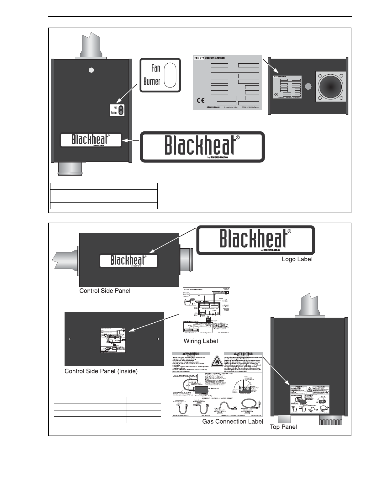
replacement signs or labels. See Page 3, Figure 1
through Page 3, Figure 2.
Page 9
SECTION 1: HEATER SAFETY
3 of 73
Figure 1: Bottom and Back Panel Label Placement
Figure 2: Control Side Label Placement
Logo Label
Fan/Burner Label
Bottom Panel
Rating Plate Label
Back Panel
Model No.
Serial No.
Appliance Type
Gas Pressure
at Manifold
Normal Input Rating
(Net Calorific Value)
Min. Input Rating
(Net Calorific Value)
Country of
Destination
Year of
Production
Category
Orifice Size
Electrical
Rating
V
Hz
W
Gas Type
Infrared Radiant Tube Heater
This applicance must be installed in accordance with the
rules in force, and used only in a sufficiently ventilated space.
Consult instructions before installation and use of this applicance.
0063
Model No.
Serial No.
Appliance Type
Gas Pressure
at Manifold
Normal Input Rating
(Net Calorific Value)
Min. Input Rating
(Net Calorific Value)
Country of
Destination
Year of
Production
Category
Orifice Size
Electrical
Rating
V
Hz
W
Gas Type
Infrared Radiant Tube Heater
This applicance must be installed in accordance with the
rules in force, and used only in a sufficiently ventilated space.
Consult instructions before installation and use of this applicance.
0063
Description Part Number
Logo Label 91033200
Rating Plate Label 91031300
Fan/Burner Label 91033300
Description Part Number
Logo Label 91033200
Wiring Diagram Label 91031404
Gas Connection Label 91018122
Page 10
BLACKHEAT® HE INSTALLATION OPERATION AND SERVICE MANUAL
4 of 73
SECTION 2: INSTALLER RESPONSIBILITY
• To install the heater, as well as the gas and electrical
supplies, in accordance with applicable specifications
and codes. Roberts-Gordon Europe Limited recommends the installer contact a local Building Inspector
or Fire Marshal for guidance.
• To use the information given in a layout drawing and
in the manual together with the cited codes and
regulations to perform the installation.
• To install the heater in accordance with the
clearances to combustibles.
• To furnish all needed materials not furnished as
standard equipment.
• To plan location of supports.
• To provide access to burners for servicing on all
sides, for burner removal.
• To provide the owner with a copy of this Installation,
Operation and Service Manual.
• To never use heater as support for ladder or other
access equipment and never hang or suspend
anything from heater.
• To ensure there is adequate air circulation around the
heater and to supply air for combustion, ventilation
and distribution in accordance with local codes.
• To safely and adequately install heater using materials with a minimal working load of 33 kg.
• To ensure the heater is placed in an approved
application.
2.1 Low Level User Instructions
In all situations, clearances to combustibles must be
maintained. Signs should be posted in storage areas to
specify the maximum stacking height of items placed
below heater to maintain required clearances to
combustibles. Minimum clearances must be maintained
from vehicles parked below the heater. Caution should be
used when running the system near combustible
materials such as wood, paper, rubber, etc. Consideration
should be given to partitions, storage racks, hoists,
building construction, etc.
A laminated wall tag is available for the heater as a
permanent reminder of the safety instructions and the
importance of the required clearances to combustibles.
Please contact Roberts-Gordon Europe Limited or your
ROBERTS GORDON
®
independent distributor to obtain
the wall tag. Affix the tag by peeling off the backing of the
adhesive strips on the rear surface and position the tag
on a wall near the heater (e.g. thermostat).
A copy of the wall tag (P/N 91037912) is illustrated on the
back cover. This copy of the wall tag can be affixed on the
wall near the heater. Know your model number and
installed configuration. Model number and installed
configuration are found on the burner and in the
Installation, Operation and Service Manual. Write the
largest clearance dimensions with permanent ink
according to your model number and configuration in the
open spaces on the tag.
2.2 Corrosive Chemicals
Roberts-Gordon Europe Limited cannot be responsible
for ensuring that all appropriate safety measures are
undertaken prior to installation; this is entirely the
responsibility of the installer. It is essential that the
contractor, the sub-contractor, or the owner identifies the
presence of combustible materials, corrosive chemicals
or halogenated hydrocarbons* anywhere in the premises.
* Halogenated Hydrocarbons are a family of chemical
compounds characterized by the presence of halogen
elements (fluorine, chlorine, bromine, etc.). These compounds are frequently used in refrigerants, cleaning
agents, solvents, etc. If these compounds enter the air
supply of the burner, the lifespan of the heater components will be greatly reduced. An outside air supply must
be provided to the burners whenever the presence of
these compounds is suspected. Warranty will be invalid
if the heater is exposed to halogenated hydrocarbons.
2.3 National Standards and Applicable Codes
All appliances must be installed in accordance with the
latest revision of the applicable standards and national
codes. This refers also to the electric, gas and venting
installation. Note: Additional standards for installations in
Public Garages, Aircraft Hangars, etc. may be applicable.
The heater must not be operated in environmental
temperatures below 0° C.
CAUTION
Product Damage Hazard
Do not use heater in area containing
corrosive chemicals.
Refer to appropriate Material Safety Data
Sheets (MSDS).
Failure to follow these instructions can result
in product damage.
Page 11
SECTION 3: CLEARANCES TO COMBUSTIBLES
5 of 73
SECTION 3: CLEARANCES TO COMBUSTIBLES
3.1 Required Clearances to Combustibles
Clearances are the required distances that combustible
objects must be away from the heater to prevent fire
hazards. Caution should be used when running the
system near combustibles. Combustibles are materials
that may catch on fire and include common items such as
wood, paper, rubber, fabric, etc. Maintain clearances to
combustibles at all times for safety.
Clearances for all heater models are located on Page 6,
Figure 3 through Page 9, Figure 16 in this manual. Check
the clearances on each burner for the model heater being
installed to make sure the product is suitable for your
application and the clearances are maintained. Read and
follow the safety guidelines below:
• Keep petrol or other combustible materials including
flammable objects, liquids, dust or vapours away from
this heater or any other appliance.
• Do not spray aerosols in the vicinity of this appliance.
• The stated clearances to combustibles represents a
surface temperature of 50° C (90° F) above room
temperature. Building materials with a low heat toler-
ance (such as plastics, vinyl siding, canvas, tri-ply,
etc) may be subject to degradation at lower temperatures. It is the installer’s responsibility to assure that
adjacent materials are protected from degradation.
• Maintain clearances from heat sensitive equipment
and workstations.
• Maintain clearances from vehicles parked below the
heater.
• Maintain clearances from swinging and overhead
doors, overhead cranes, vehicle lifts, partitions,
storage racks, hoists, building construction, etc.
• In locations used for the storage of combustible materials, signs must be posted to specify the
maximum permissible stacking height to maintain
required clearances from the heater to the
combustibles. Signs must be posted adjacent to the
heater thermostat. In the absence of a thermostat,
signs must be posted in a conspicuous location.
• Consult local Building Inspector, Fire Insurance
Carrier or other authorities for approval of proposed
installation when there is a possibility of exposure to
combustible airborne materials or vapours.
• Hang heater in accordance to the minimum
suspension requirements on Page 11, Section 5.
• If the radiant tubes must pass through the building
structure, be sure that adequate sleeving and fire
stop is installed to prevent scorching and/or fire
hazard.
WARNING
Fire Hazard
Keep all flammable objects, liquids and
vapors the minimum required clearances to
combustibles away from heater.
Some objects will catch fire or explode when
placed close to heater.
Failure to follow these instructions can result
in death, injury or property damage.
Page 12
BLACKHEAT® HE INSTALLATION OPERATION AND SERVICE MANUAL
6 of 73
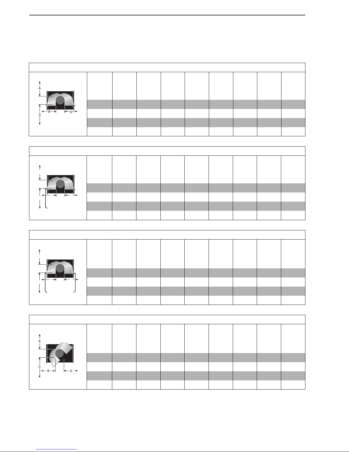
3.2 Clearances Data - Linear and Double Linear
NOTE: 1. All dimensions are from the surfaces of all tubes, couplings, tees, elbows and crosses.
2. Clearances B, C and D can be reduced by 50% after 7500 mm of tubing downstream
from the burner.
3. All measurements are in millimeters.
FIGURE 3: LINEAR & DOUBLE LINEAR, HORIZONTAL MOUNTS
Model
HE15ST
HE30DL
HE20ST
HE40DL
HE25ST
HE50DL
HE30ST
HE60DL
HE35ST
HE70DL
HE40ST
HE45ST
HE50ST
A 150 150 150 150 150 150 200 200
B 890 970 970 1020 1170 1220 1280 1330
C 1570 1650 1650 1780 1930 1970 2010 2080
D 890 970 970 1020 1170 1220 1280 1330
FIGURE 4: LINEAR & DOUBLE LINEAR, ONE SIDE REFLECTOR
Model
HE15ST
HE30DL
HE20ST
HE40DL
HE25ST
HE50DL
HE30ST
HE60DL
HE35ST
HE70DL
HE40ST
HE45ST
HE50ST
A 150 150 150 150 150 150 200 200
B 230 230 230 230 230 230 230 230
C 1580 1760 1760 1930 2090 2130 2160 2240
D 1200 1380 1380 1500 1660 1710 1760 1860
A
C
D
B
FIGURE 5: LINEAR & DOUBLE LINEAR, TWO SIDE REFLECTORS
Model
HE15ST
HE30DL
HE20ST
HE40DL
HE25ST
HE50DL
HE30ST
HE60DL
HE35ST
HE70DL
HE40ST
HE45ST
HE50ST
A 150 150 150 150 150 150 200 200
B 590 640 640 690 820 860 890 1020
C 1660 1810 1810 1960 2110 2160 2210 2320
D 590 640 640 690 820 860 890 1020
A
C
D
B
FIGURE 6: LINEAR & DOUBLE LINEAR, 45° MOUNT
Model
HE15ST
HE30DL
HE20ST
HE40DL
HE25ST
HE50DL
HE30ST
HE60DL
HE35ST
HE70DL
HE40ST
HE45ST
HE50ST
A 200 200 200 250 250 275 300 300
B 200 200 200 200 200 200 200 200
C 1500 1660 1660 1860 1960 2030 2110 2160
D 1370 1520 1520 1630 1750 1820 1880 2000
Page 13
SECTION 3: CLEARANCES TO COMBUSTIBLES
7 of 73
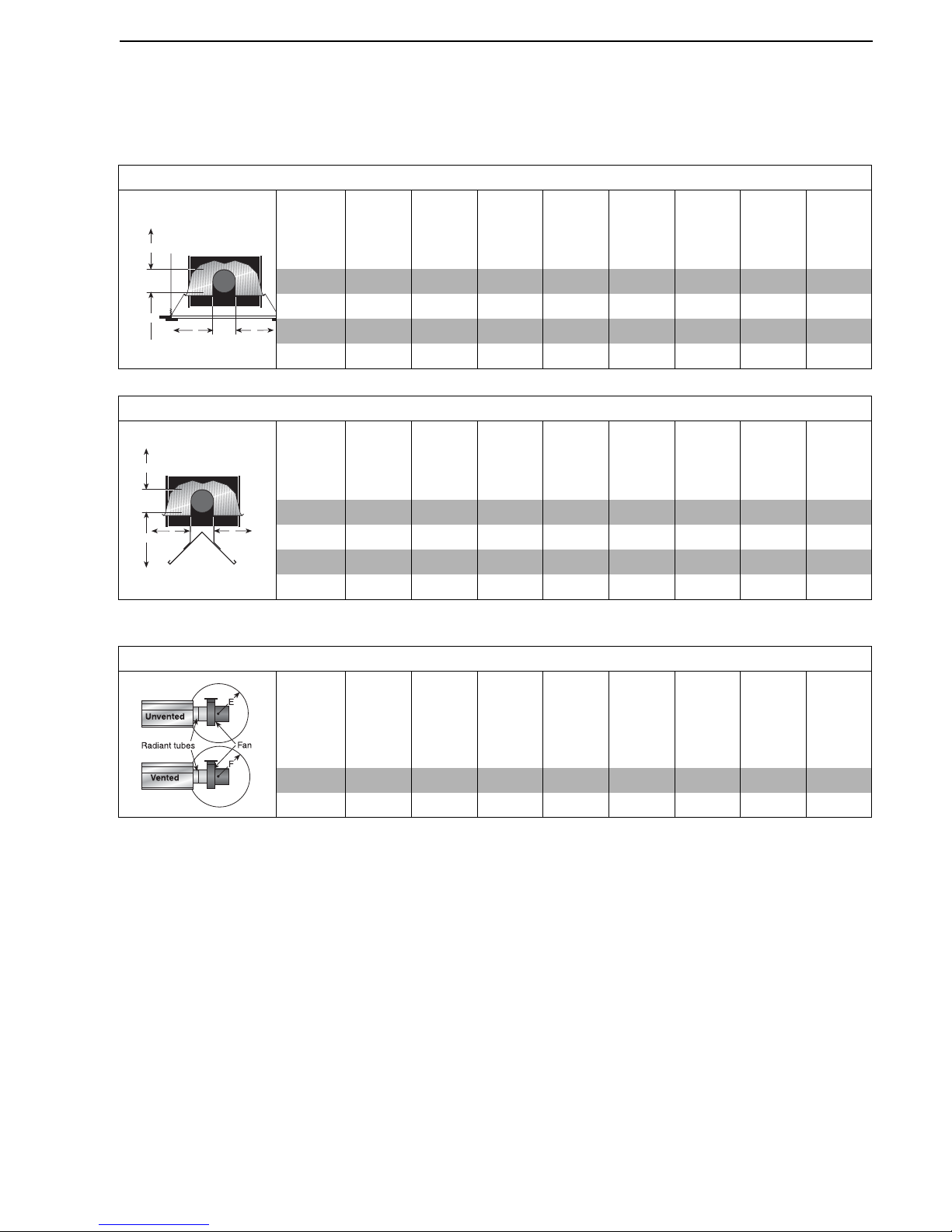
NOTE: 1. All dimensions are from the surfaces of all tubes, couplings, tees, elbows and crosses.
2. Clearances B, C and D can be reduced by 50% after 7500 mm of tubing downstream
from the burner.
3. All measurements are in millimeters.
** When installed in the first 3 m.
FIGURE 7: LINEAR & DOUBLE LINEAR, 2 FOOT DECO GRILLE, PROTECTIVE GRILLE
Model
HE15ST
HE30DL
HE20ST
HE40DL
HE25ST
HE50DL
HE30ST
HE60DL
HE35ST
HE70DL
HE40ST
HE45ST
HE50ST
A 150 150 150 150 150 150 200 200
B 890 970 970 1020 1170 1220 1280 1330
C 1570 1650 1650 1780 1930 1970 2010 2080
D 890 970 970 1020 1170 1220 1280 1330
A
C
D
B
FIGURE 8: UNDERSHIELD**
Model
HE15ST
HE30DL
HE20ST
HE40DL
HE25ST
HE50DL
HE30ST
HE60DL
HE35ST
HE70DL
HE40ST
HE45ST
HE50ST
A 150 150 150 150 150 150 - -
B 990 1020 1270 1270 1370 1400 - -
C 840 965 11 20 11 2 0 1220 1270 - -
D 990 1020 1270 1270 1370 1400 - -
A
C
D
B
FIGURE 9: LINEAR & DOUBLE LINEAR, VENTING
Model
HE15ST
HE30DL
HE20ST
HE40DL
HE25ST
HE50DL
HE30ST
HE60DL
HE35ST
HE70DL
HE40ST
HE45ST
HE50ST
E 1000 1000 1000 1000 1000 1000 1000 1000
F 500 500 500 500 500 500 500 500
Page 14
BLACKHEAT® HE INSTALLATION OPERATION AND SERVICE MANUAL
8 of 73
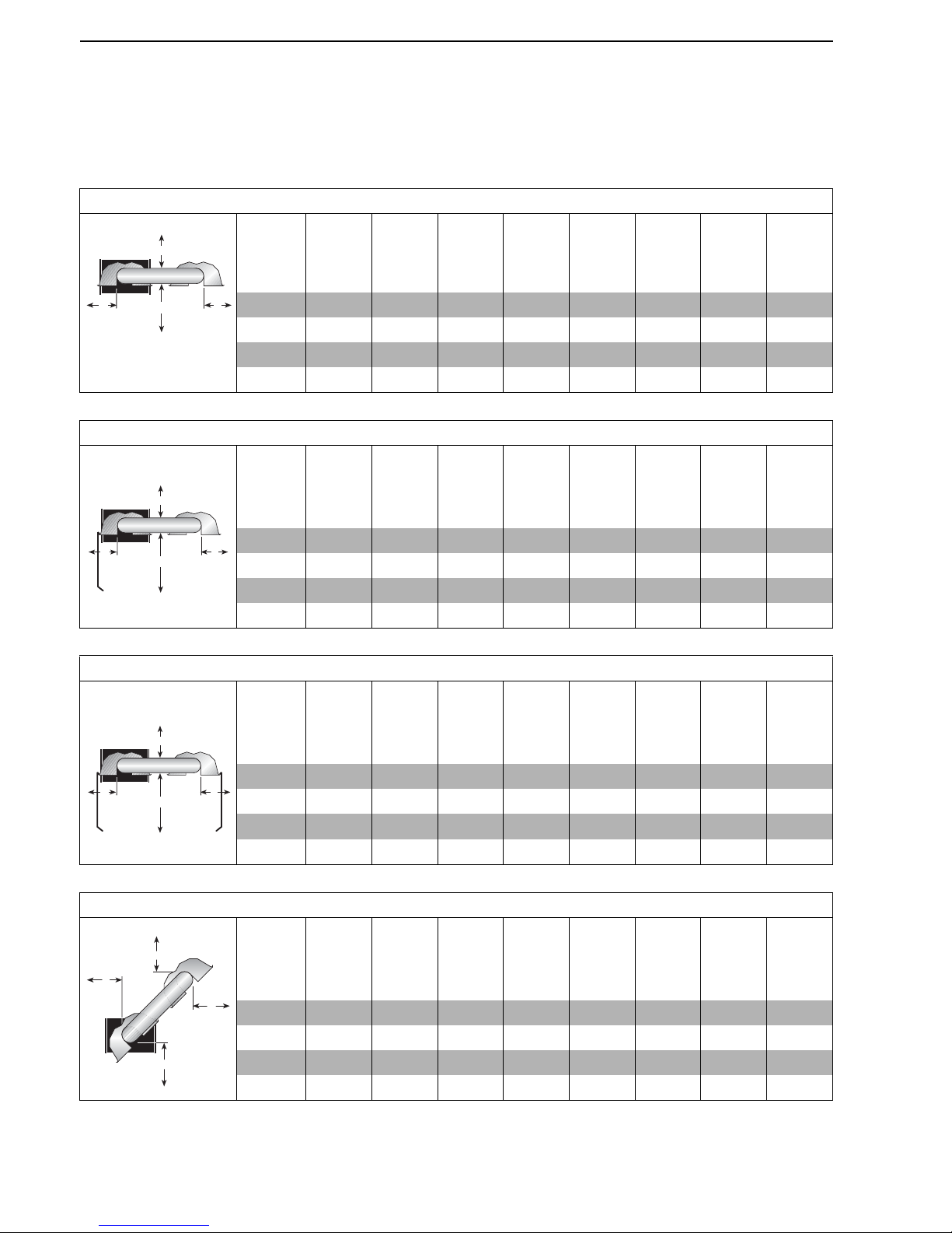
3.3 Clearances Data - U-Tube
NOTE: 1. All dimensions are from the surfaces of all tubes, couplings, tees, elbows and crosses.
2. Clearances B, C and D can be reduced by 50% after 7500 mm of tubing downstream
from the burner.
3. All measurements are in millimeters.
4. Add 60 mm clearance to uncovered u-tube.
.
FIGURE 10: U-TUBE, HORIZONTAL MOUNT
Model
HE15UT
HE20UT
HE25UT
HE30UT
HE35UT
HE40UT
HE45UT
HE50UT
A 150 150 150 150 150 150 200 200
B 890 970 970 1020 1170 1220 1270 1380
C 1580 1730 1730 1910 1980 2050 2110 2210
D 760 940 940 1000 1090 1150 1200 1300
A
C
D
B
FIGURE 11: U-TUBE, ONE SIDE REFLECTOR
Model
HE15UT
HE20UT
HE25UT
HE30UT
HE35UT
HE40UT
HE45UT
HE50UT
A 150 150 150 150 150 150 200 200
B 230 230 230 230 230 230 230 230
C 1580 1760 1760 1930 2090 2130 2160 2240
D 1200 1380 1380 1500 1660 1710 1760 1860
A
C
D
B
FIGURE 12: U-TUBE, TWO SIDE REFLECTORS
Model
HE15UT
HE20UT
HE25UT
HE30UT
HE35UT
HE40UT
HE45UT
HE50UT
A 150 150 150 150 150 150 200 200
B 590 640 640 690 820 860 890 1020
C 1660 1810 1810 1960 2110 2160 2210 2320
D 590 640 640 690 820 860 890 1020
A
C
D
B
FIGURE 13: U-TUBE, FULL 45° MOUNT
Model
HE15UT
HE20UT
HE25UT
HE30UT
HE35UT
HE40UT
HE45UT
HE50UT
A 200 200 200 200 200 200 200 200
B 200 200 200 200 200 200 200 200
C 1500 1650 1650 1860 1960 2040 2110 2160
D 1070 1170 1170 1320 1550 1620 1680 1780
B
C
D
A
Page 15
SECTION 3: CLEARANCES TO COMBUSTIBLES
9 of 73
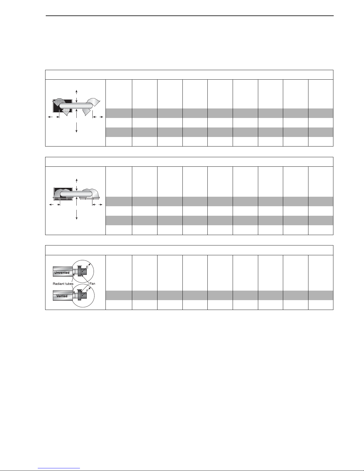
NOTE: 1. All dimensions are from the surfaces of all tubes, couplings, tees, elbows and crosses.
2. Clearances B, C and D can be reduced by 50% after 7500 mm of tubing downstream
from the burner.
3. All measurements are in millimeters.
4. Add 60 mm clearance to uncovered u-tube.
FIGURE 14: U-TUBE, OPPOSITE 45° TILT
Model
HE15U
HE20UT
HE25UT
HE30UT
HE35UT
HE40UT
HE45UT
HE50UT
A 200 200 200 250 250 275 300 300
B 1370 1530 1530 1630 1780 1830 1880 1930
C 1500 1650 1650 1860 1960 2040 2110 2160
D 560 560 560 560 560 560 560 560
A
C
D
B
FIGURE 15: U-TUBE, PROTECTIVE GRILLE
Model
HE15UT
HE20UT
HE25UT
HE30UT
HE35UT
HE40UT
HE45UT
HE50UT
A 150 150 150 150 150 150 200 200
B 890 970 970 1020 1170 1220 1270 1380
C 1580 1730 1730 1910 1980 2050 2110 2210
D 760 940 940 1000 1090 1150 1200 1300
A
C
D
B
FIGURE 16: U-TUBE, VENTING
Model
HE15UT
HE20UT
HE25UT
HE30UT
HE35UT
HE40UT
HE45UT
HE50UT
E 1000 1000 1000 1000 1000 1000 1000 1000
F 500 500 500 500 500 500 500 500
Page 16
BLACKHEAT® HE INSTALLATION OPERATION AND SERVICE MANUAL
10 of 73
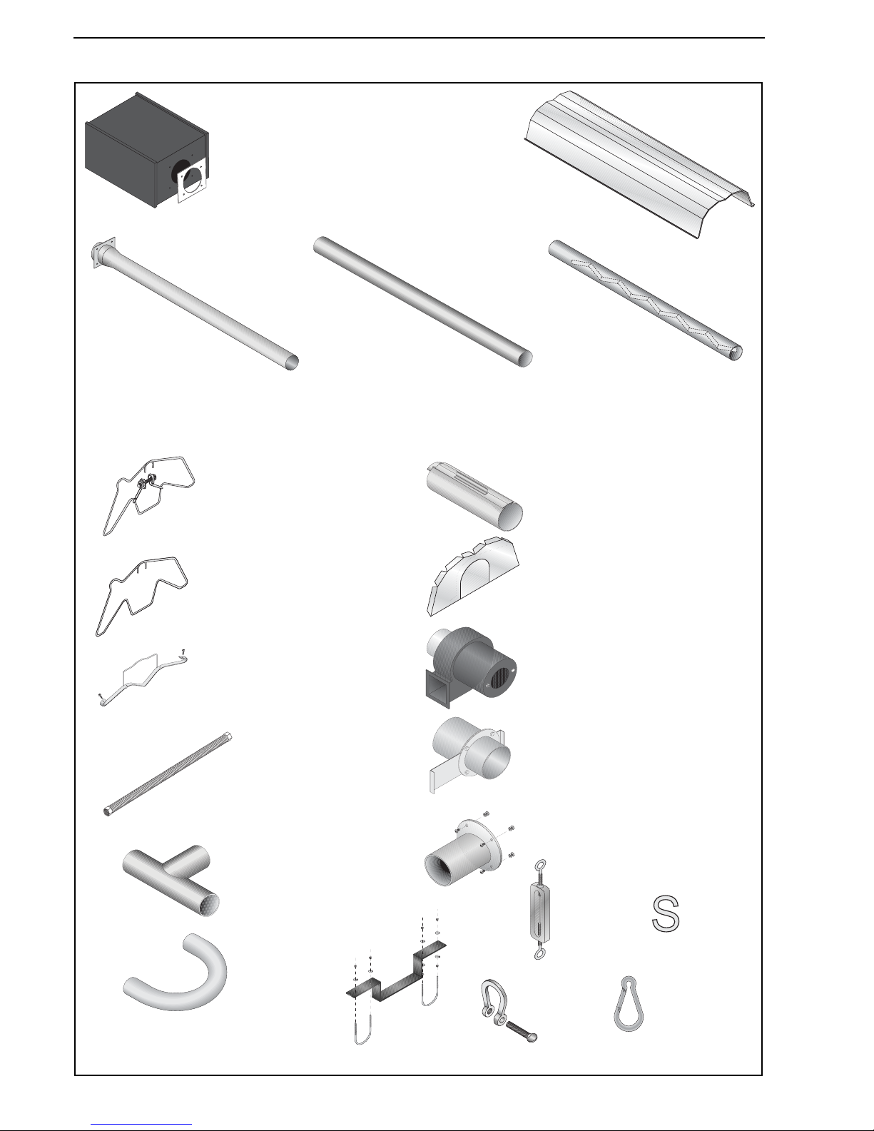
SECTION 4: MAJOR COMPONENT DESCRIPTIONS
Burner (shown with Tube
Gasket)
Must be installed with the
flame observation window
facing down.
Reflector
(Aluminium or
Stainless Steel)
Alternate overlap as
shown on overview.
Minimum overlap is 160 mm.
Coupling Assembly
with Lock
Reflector End Cap
Punch out center section to
accommodate tube.
Fan Assembly (Includes Flange)
Fan assembly is attached to the last
section of heat exchanger tubing
(fan tube).
Tube and Reflector Hanger
Suspend system from these
hangers.
Flex Gas Line
Tube
Heat treated aluminised tube
supplied in 3000 mm lengths.
Burner Tube
Supplied in 3000 mm lengths.
Burner tube is always the first
tube after the burner.
Reflector Support Strap, Wire
Form & #8 x 3/4 Screw
Fan Tube with Internal Swirler
Supplied in 3000 mm lengths. Fan
tube is always the last tube on the
heater where the fan is attached.
The swirler is welded inside of the
tube end.
Fan Flange Assembly
and Screws
U-tube
Height
Adjuster
Bow
Shackle
Tee
Assembly
U-tube
Support
Bracket
Damper Flange Assembly
For use on Multiburner Systems.
Tube and Reflector Hanger
with Clamp Package
Position this hanger no more
than 100 mm away from the
burner assembly.
Spring
Hook
S-hook
Page 17
SECTION 5: GENERAL SUSPENSION DETAILS
11 of 73
SECTION 5: GENERAL SUSPENSION DETAILS
To ensure your safety, and comply with the terms of the
warranty, all units must be installed in accordance with
these instructions.
The gas or the electrical supply lines must not be used to
support the heater.
Do not locate the gas or electrical supply lines directly
over the path of the flue products from the heater.
The heater must be installed in a location that it is readily
accessible for servicing.
The heaters must be installed with clearances to
combustibles as indicated on the rating plate and in this
manual.
The minimum and maximum gas inlet pressures must be
maintained as indicated on the rating plate. Typical
installation configurations are shown on Page 12, Figure
17.
Suspension chain is not supplied as standard equipment.
NOTE: Some models may receive S-hooks (P/N
91907302) or spring hooks (P/N 91903300), rather than
bow shackles.
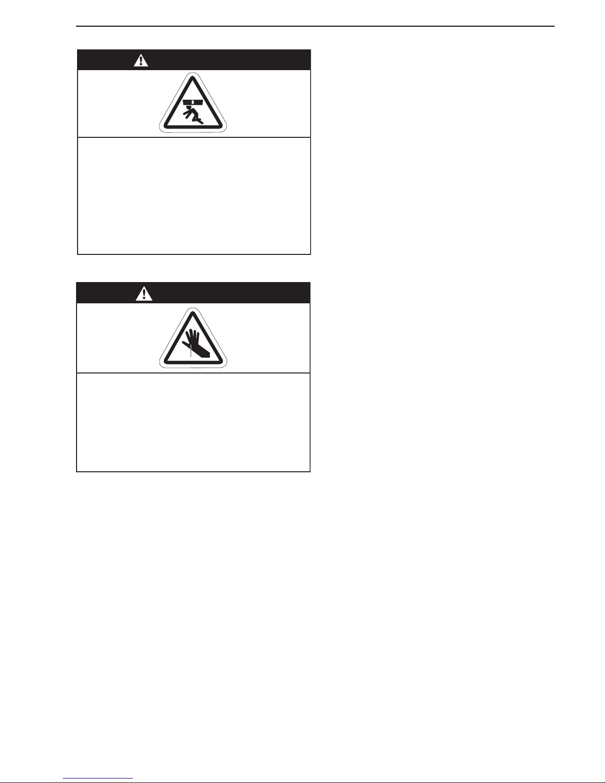
WARNING
Severe Injury Hazard
Secure burner to burner tube with bolts and
lockwashers.
Hang heater with materials with a minimum
working load of 75 lbs (33 kg).
Failure to follow these instructions can result
in death, injury or property damage.
WARNING
Cut/Pinch Hazard
Wear protective gear during installation,
operation and service.
Edges are sharp.
Failure to follow these instructions can result
in injury.
Page 18
BLACKHEAT® HE INSTALLATION OPERATION AND SERVICE MANUAL
12 of 73
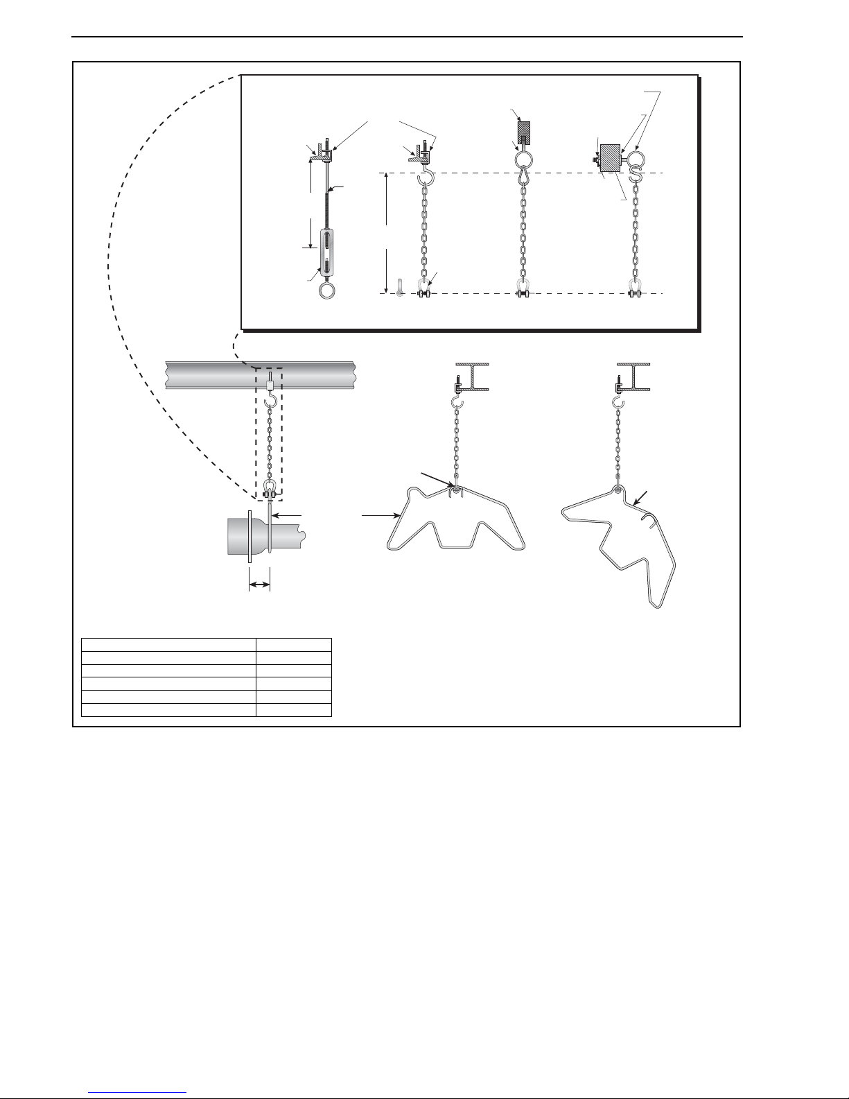
Figure 17: Critical Hanger Placement
For suspension angles other than shown, additional chain supports may be required.
* Allows for thermal expansion of system.
Hanger
Side View
Front View
Hanger
Bow Shackle
I-Beam
I-Beam
Beam
Clamp
Bow
Shackle
Anchor
Concrete
Beam
Locknut
Washer
Screw Hook
min. 10 mm
Washer
Wood
Beam
Turnbuckle
(not included)
600 mm
minimum*
300 mm
minimum*
10 mm
Rod
Typical Suspension Details
45° Angle
100 mm
Max.
Description Part Number
Burner Tube 03051100
S-hook 91907302
Spring Hook 91903300
Bow Shackle E0007576
Tube/Reflector Hanger 03090100
Page 19
SECTION 6: LINEAR & DOUBLE LINEAR HEATER INSTALLATION
13 of 73
SECTION 6: LINEAR & DOUBLE LINEAR HEATER INSTALLATION
The figures in this section provide a general overview of
component placement in a Linear and Double Linear
system. The location of some components such as
supports and couplings is crucial for proper installation.
Assemble the heater components as shown on Page 14,
Figure 18.
For optional reflector configurations for linear heaters see
Page 6, Figure 3 through Page 7, Figure 9. Install
appropriate suspension hardware, beam clamps, chain or
rod at predetermined locations. Adjustments of chain
length will provide uniform pitch.
If any step is unclear, please contact Roberts-Gordon
Europe Limited at +44 (0)121 506 7700.
6.1 Linear Standard Parts List
* PVC coating must be removed prior to installation.
** Some models may receive S-hooks (P/N 91907302) or
spring hooks (P/N 91903300), rather than bow shackles.
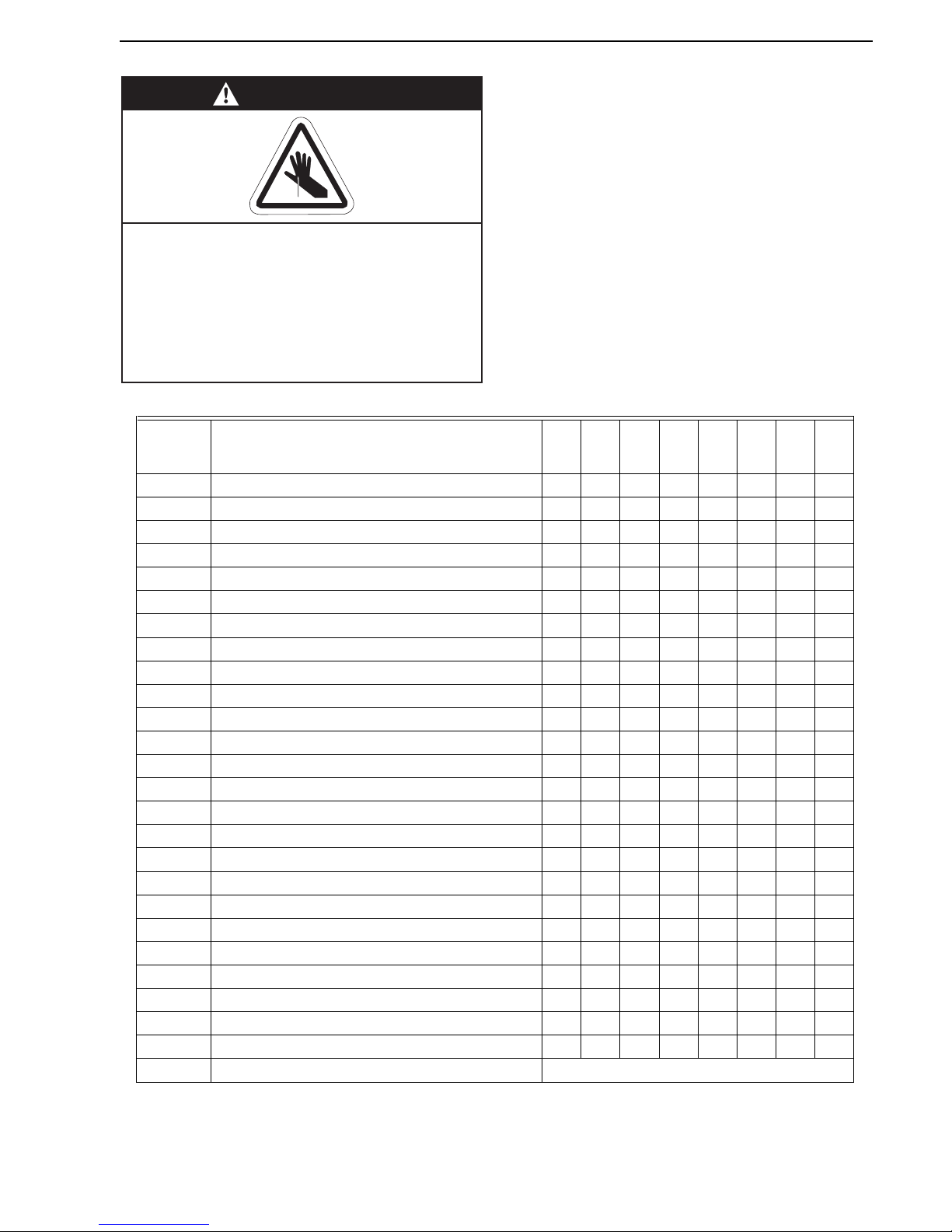
WARNING
Cut/Pinch Hazard
Wear protective gear during installation,
operation and service.
Edges are sharp.
Failure to follow these instructions can result
in injury.
Part No. Description
HE15ST
HE20ST
HE25ST
HE30ST
HE35ST
HE40ST
HE45ST
HE50ST
033XXXXX Burner Assembly (Input and Fuel Varies) 1 1 1 11111
07260053 Fan Package 3 IP55 1 1 1 11111
07240004Linear Package 11111111
03360115 Restrictor Plate BH HE 15 1 - - - - - - -
03360120 Restrictor Plate BH HE 20 - 1 - - - - - -
03360125 Restrictor Plate BH HE 25 - - 1 - - - - -
03360130 Restrictor Plate BH HE 30 - - - 1 - - - -
03360135Restrictor Plate BH HE 35 ----1---
03051600Burner Tube, 100 mm x 3048 mm 11111111
91409408Tube, 100 mm x 3048 mm -1122233
S5127WFan Tube, 100 mm x 3048 mm, with 3048 mm Swirler -1111111
S5134W Fan Tube, 100 mm x 3048 mm, with 2134 mm Swirler 1 - - - - - - -
01329600Standard Coupling Assembly 12233344
01329700Coupling Lock 12233344
02750303Reflector, Aluminium, 2439 mm 34466677
027503SS Reflector, Stainless Steel, 2439 mm (Optional)* 3 4 4 66677
02750800Reflector End Cap, Aluminium 22222222
027508SHReflector End Cap, Stainless (Optional)* 22222222
03090100Tube and Reflector Hanger 34455566
01318901Tube Clamp Package (including Nut, Washer & Bolt) 11111111
91908004Wire Form 23355566
94320812 Screw #8 x 3/4, (Goes with 03050000) 4 6 6 10 10 10 12 12
03050000Reflector Support Strap 23355566
E0007576Bow Shackle** 34455566
91107720U-Clip Package (20 Pieces) 11111111
S7199K Damper Flange Assembly (For use on Multiburner Systems) 1 Per Heater
Page 20
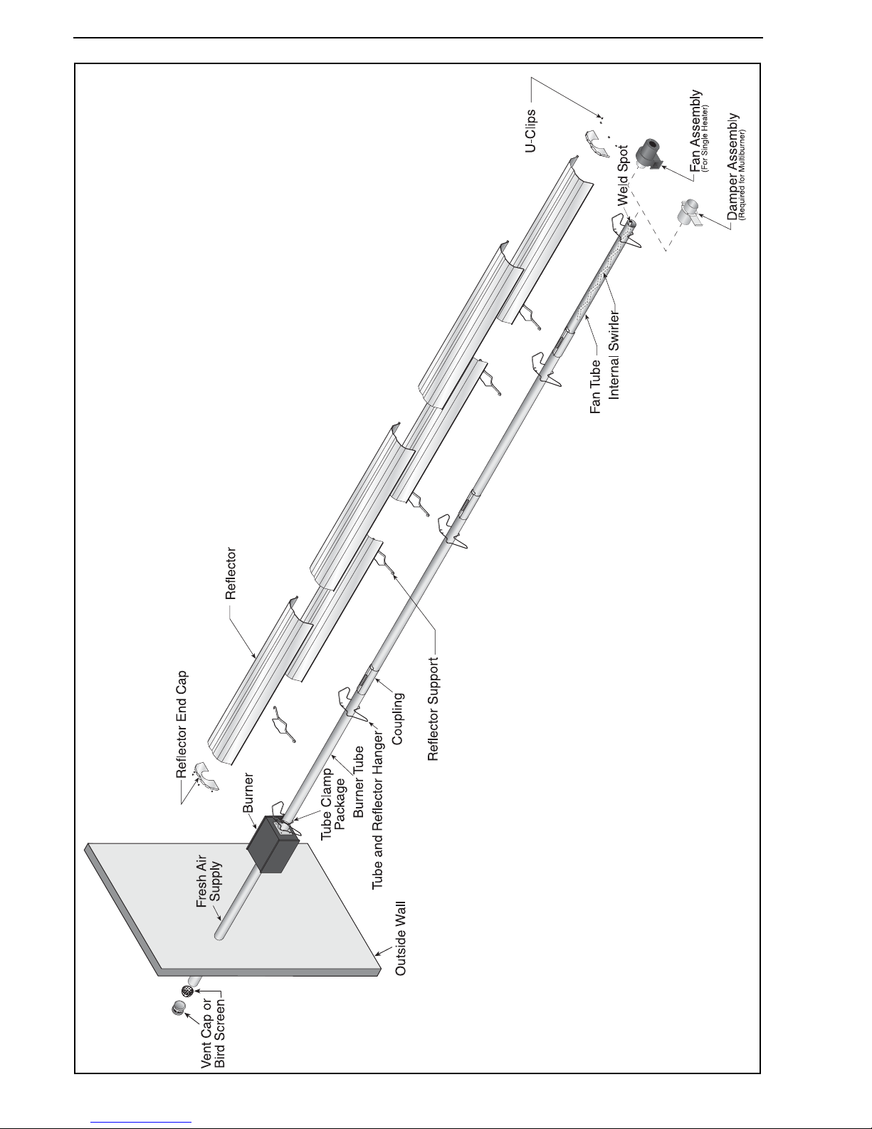
BLACKHEAT® HE INSTALLATION OPERATION AND SERVICE MANUAL
14 of 73
Figure 18: Linear General Assembly Overview
Page 21
SECTION 6: LINEAR & DOUBLE LINEAR HEATER INSTALLATION
15 of 73
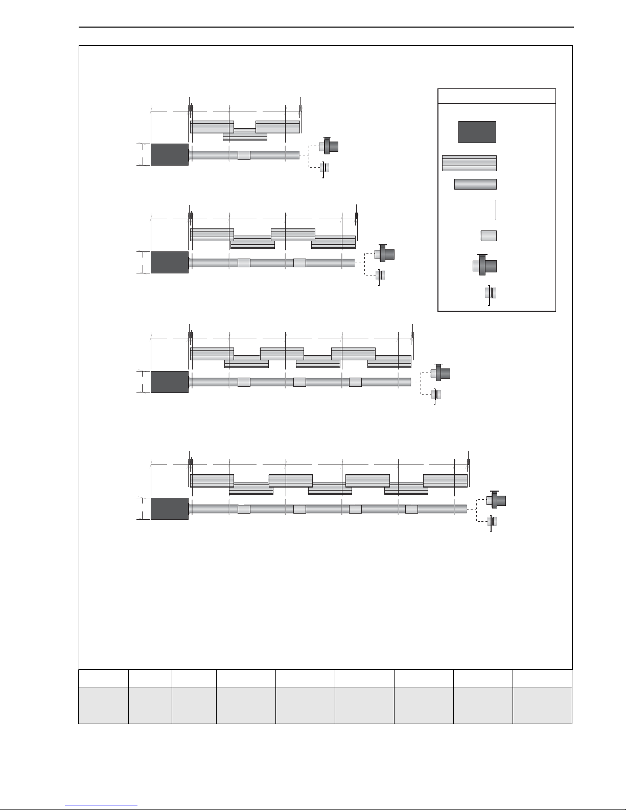
Figure 19: Linear Layout Overview
Model HE15ST HE20ST HE25ST HE30ST HE35ST HE40ST HE45ST HE50ST
Reflector
Overlap
(approx.)
700 mm 250 mm 250 mm 530 mm 530 mm 530 mm 330 mm 330 mm
a = reflector width (not shown) - 365 mm
b = end cap to burner/fan - 50 mm
c = end cap to hanger - 50 mm
d = distance first hanger - 2290 mm
e = distance typical between hangers - 3050 mm
f = burner height - 241 mm
g = burner length - 445 mm
Burner
Reflector
Tube
Tube/Reflector
Hanger
Coupling
Assembly
Fan
Assembly
LEGEND
Damper
Assembly
HE20ST
HE25ST
c
b
de
b
e
HE30ST
HE35ST
HE40ST
c
b
de
b
e e
HE45ST
HE50ST
c
b
de
b
e e e
g
c
b
de
b
HE15ST
f
g
f
g
f
g
f
Page 22
BLACKHEAT® HE INSTALLATION OPERATION AND SERVICE MANUAL
16 of 73
6.2 Double Linear Standard Parts List
* PVC coating must be removed prior to installation.
** Some models may receive S-hooks (P/N 91907302) or
spring hooks (P/N 91903300), rather than bow shackles.
Part No.
Description
HE30DL
HE40DL
HE50DL
HE60DL
HE70DL
033XXXXX Burner Assembly (Input and Fuel Varies) 2 2 2 2 2
07260053 Fan Package 3 IP55 1 1 1 1 1
07260004 Linear Package 2 2 2 2 2
03360130 Restrictor Plate BH HE 30 1 - - - -
03051600 Burner Tube, 100 mm x 3048 mm 2 2 2 2 2
91409408 Tube, 100 mm x 3048 mm - 2 2 4 4
S5127W Fan Tube, 100 mm x 3048 mm, with 3048 mm Swirler - 2 2 2 2
S5134W Fan Tube, 100 mm x 3048 mm, with 2134 mm Swirler 2 - - - -
01330203 Tee, 100 mm x 100 mm x 100 mm 1 1 1 1 1
01329600 Standard Coupling Assembly 6 8 8 10 10
01329700 Coupling Lock 6 8 8 10 10
02750303 Reflector, Aluminium, 2439 mm 6 8 8 12 12
027503SS Reflector, Stainless Steel, 2439 mm (Optional)* 6 8 8 12 12
02750800 Reflector End Cap, Aluminium 4 4 4 4 4
027508SH Reflector End Cap, Stainless (Optional)* 4 4 4 4 4
03090100 Tube and Reflector Hanger 6 8 8 10 10
01318901 Tube Clamp Package (including Nut, Washer & Bolt) 2 2 2 2 2
91908004 Wire Form 4 6 6 10 10
03050000 Reflector Support Strap 4 6 6 10 10
E0007576 Bow Shackle** 6 8 8 10 10
91107720 U-Clip Package (20 Pieces) 2 2 2 2 2
E0007582 Height Adjuster 6 8 8 10 10
94320812 Screw #8 x 3/4, (Goes with 03050000) 8 12 12 20 20
Page 23
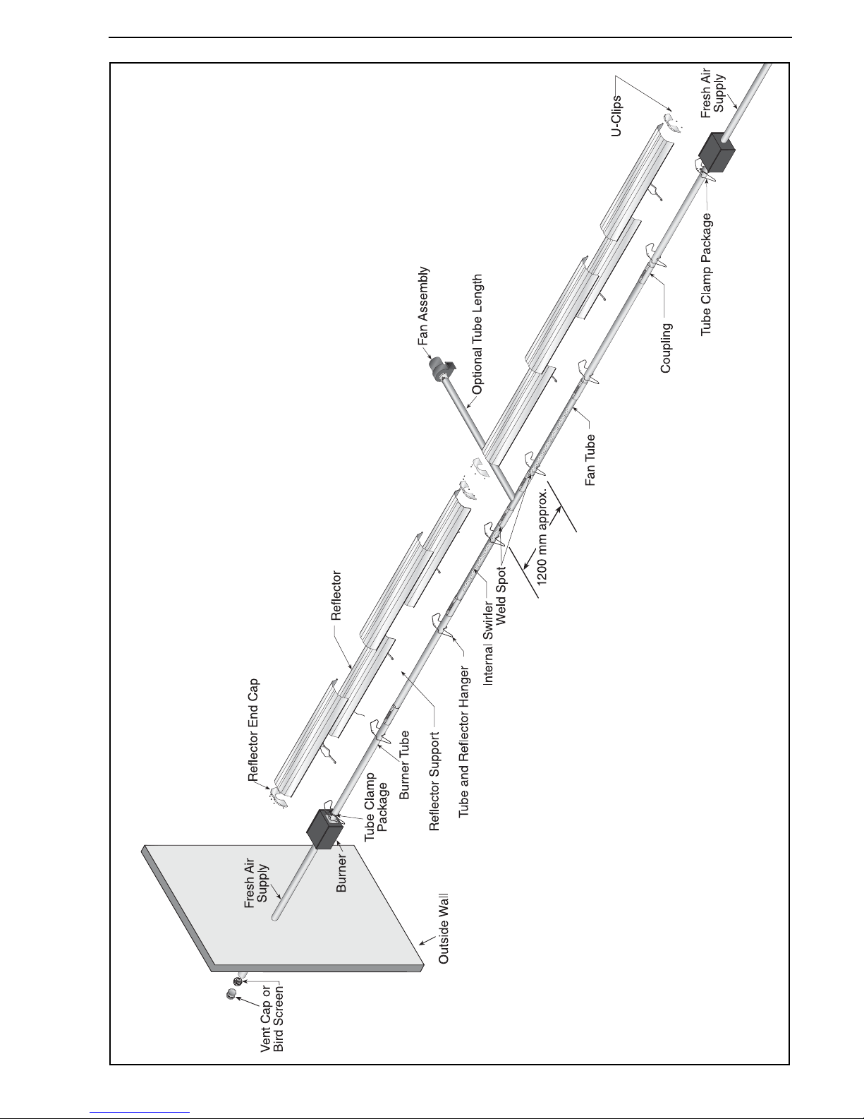
SECTION 6: LINEAR & DOUBLE LINEAR HEATER INSTALLATION
17 of 73
Figure 20: Double Linear General Assembly Overview
Page 24
BLACKHEAT® HE INSTALLATION OPERATION AND SERVICE MANUAL
18 of 73
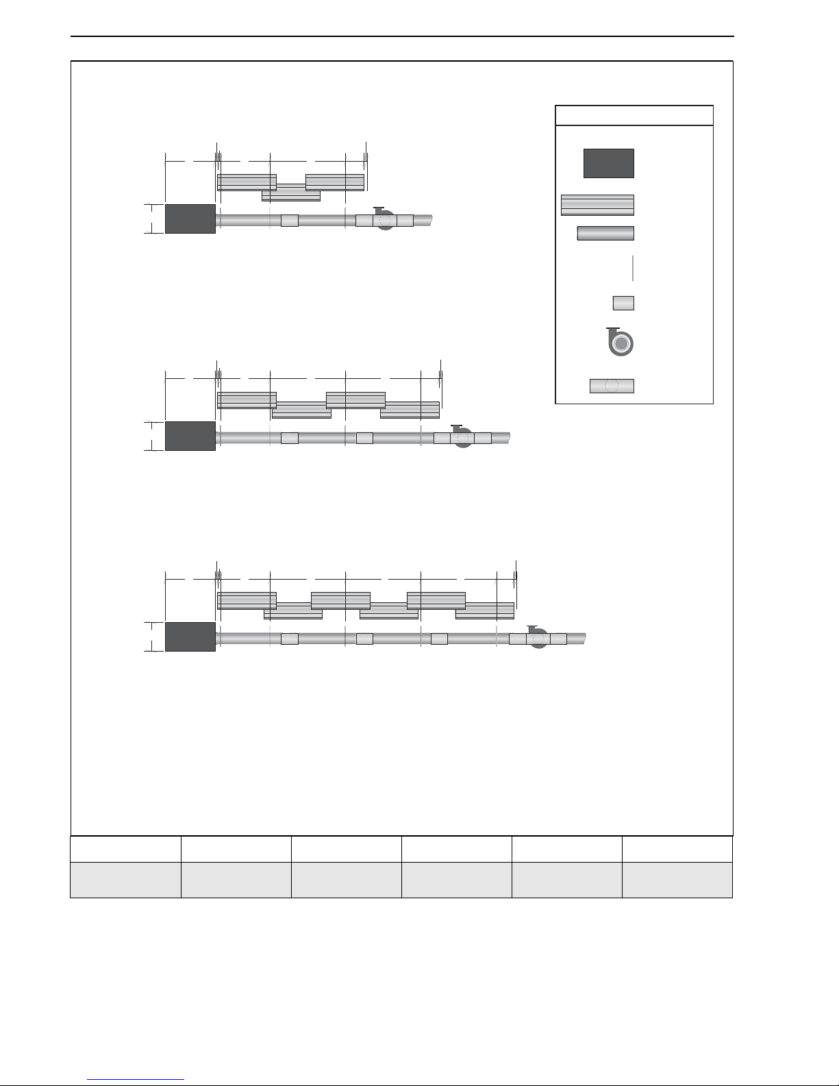
Figure 21: Double Linear Layout Overview
Model HE30DL HE40DL HE50DL HE60DL HE70DL
Reflector
Overlap (approx.)
700 mm 250 mm 250 mm 530 mm 530 mm
Tee Assembly
Burner
Reflector
Tube
Tube/Reflector
Hanger
Coupling
Assembly
Fan
Assembly
LEGEND
HE60DL
HE70DL
c
b
de
b
e e
Repeated
Opposite
Side
HE40DL
HE50DL
c
b
de
b
e
Repeated
Opposite
Side
HE30DL
g
c
b
de
b
f
Repeated
Opposite
Side
a = reflector width (not shown) - 365 mm
b = end cap to burner/fan - 50 mm
c = end cap to hanger - 50 mm
d = distance first hanger - 2290 mm
e = distance typical between hangers - 3050 mm
f = burner height - 241 mm
g = burner length - 445 mm
g
f
g
f
Page 25
SECTION 6: LINEAR & DOUBLE LINEAR HEATER INSTALLATION
19 of 73
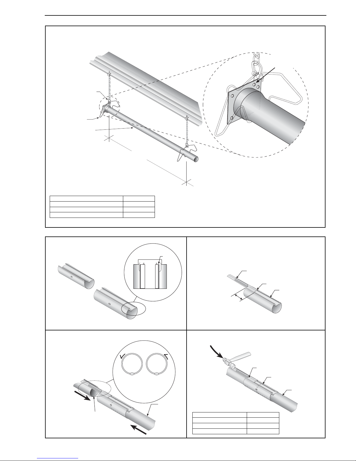
Step 6.3 Burner Tube Installation
Step 6.4 Coupling and Tube Assembly
Bow Shackle
Burner Tube
Hanger
2290 mm ± 250 mm
Note:
Tubing requires a downward
slope of 13 mm per 6000 mm
away from burner.
Weld seam
must be to the
bottom of the tube.
Offset mounting
hole must be
to the top.
Description Part Number
Burner Tube 03051600
Bow Shackle E0007576
Tube/Reflector Hanger 03090100
Tube
Tube
Orient coupling so that
the impact block is in the
2:00 or 10:00 oclock
positions
Closed
Open
Ta b
76 mm to
101 mm
Slide Bar
Coupling
Wide End
Coupling
Tube
Slide Bar
A
Close coupling
with tab
B
Start slide bar/coupling lock
onto coupling
C
Insert tubes into coupling
D
Tighten coupling to join tubes
Description Part Number
Coupling 01329600
Slide Bar/Coupling Lock 01329700
Tube 91409408
Page 26
BLACKHEAT® HE INSTALLATION OPERATION AND SERVICE MANUAL
20 of 73
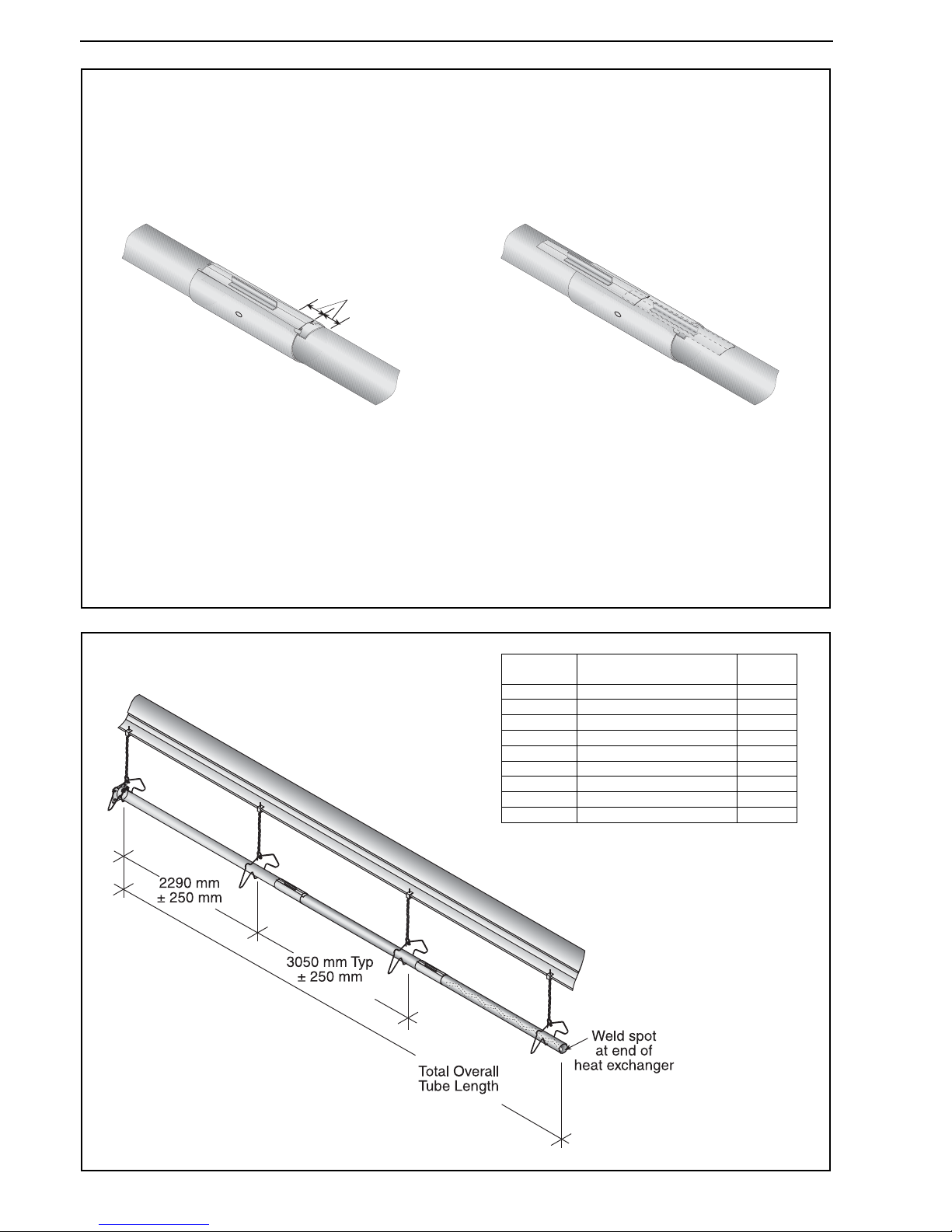
Step 6.4.1 Coupling and Tube Assembly (Continued)
Step 6.4.2 Coupling and Tube Assembly (Continued)
Incorrect Slide Bar
position
Correct Slide Bar
dimensions
± 50 mm
Drive slide bar until tight.
End of slide bar should be
within tolerance listed below.
• Repeat Step 6.4 A - D until all tubes are assembled. See Page 20, Section 6.4.2 shown below.
Tighten slide bar as shown below.
Model Overall Tube Length (mm)
Number
of Tubes
HE15ST 6000 2
HE20ST 9000 3
HE25ST 9000 3
HE30ST 12,000 4
HE35ST 12,000 4
HE40ST 12,000 4
HE45ST 15,000 5
HE50ST 15,000 5
HE55ST 18,000 6
Page 27
SECTION 6: LINEAR & DOUBLE LINEAR HEATER INSTALLATION
21 of 73
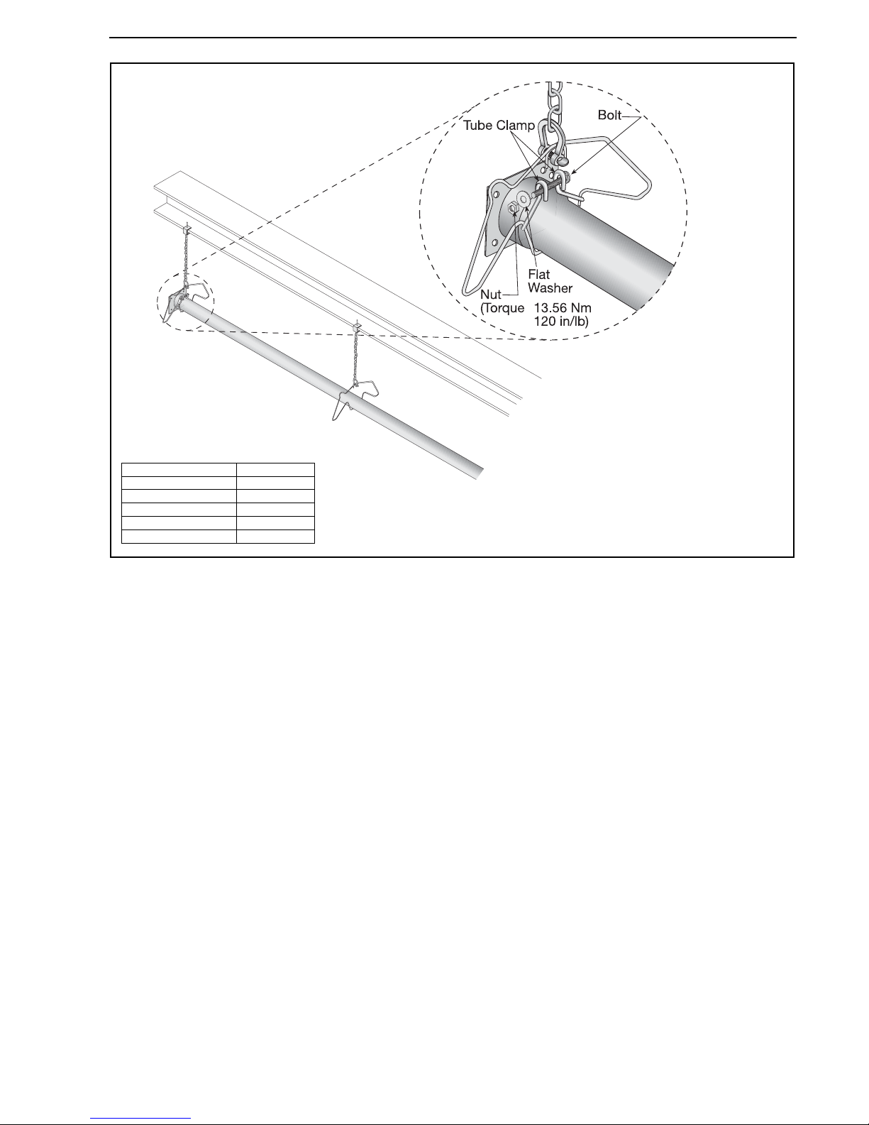
Step 6.5 Tube Clamp Package Installation
Description Part Number
Tube Clamp Package01318901
Tube Clamp 01396801
Bolt 97113940
Flat Washer 95211600
Nut 92113900
Note: Tube clamp package should be
installed 100 mm from burner tube plate.
Other hangers do not need tube clamp
packages.
Page 28
BLACKHEAT® HE INSTALLATION OPERATION AND SERVICE MANUAL
22 of 73
Step 6.6 Reflector Installation
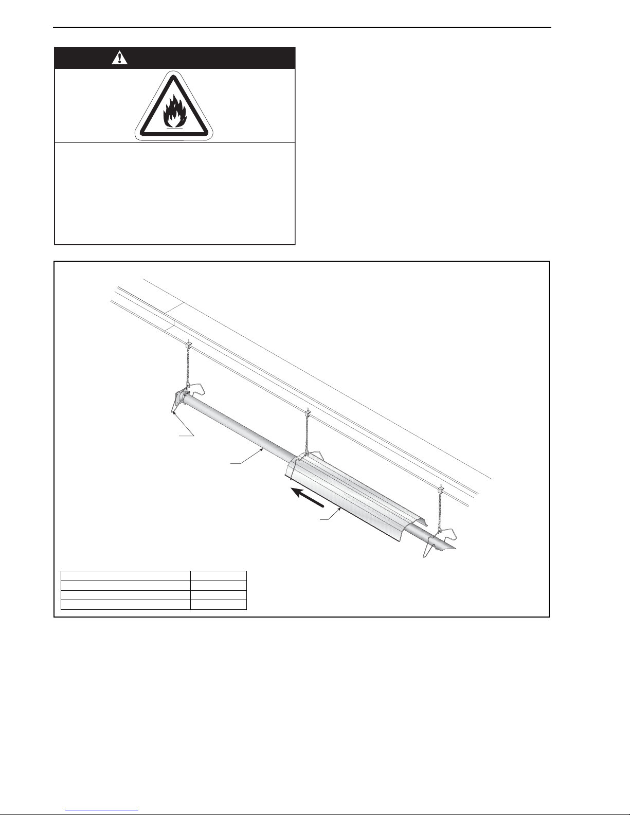
WARNING
Fire Hazard
Support reflector with reflector hanger
and support strap.
Reflector must not touch tube.
Failure to follow these instructions can result
in death, injury or property damage.
Hanger
Burner Tube
Reflector
Description Part Number
Tube/Reflector Hanger 03090100
Burner Tube 03051600
Reflector 02750303
Page 29
SECTION 6: LINEAR & DOUBLE LINEAR HEATER INSTALLATION
23 of 73
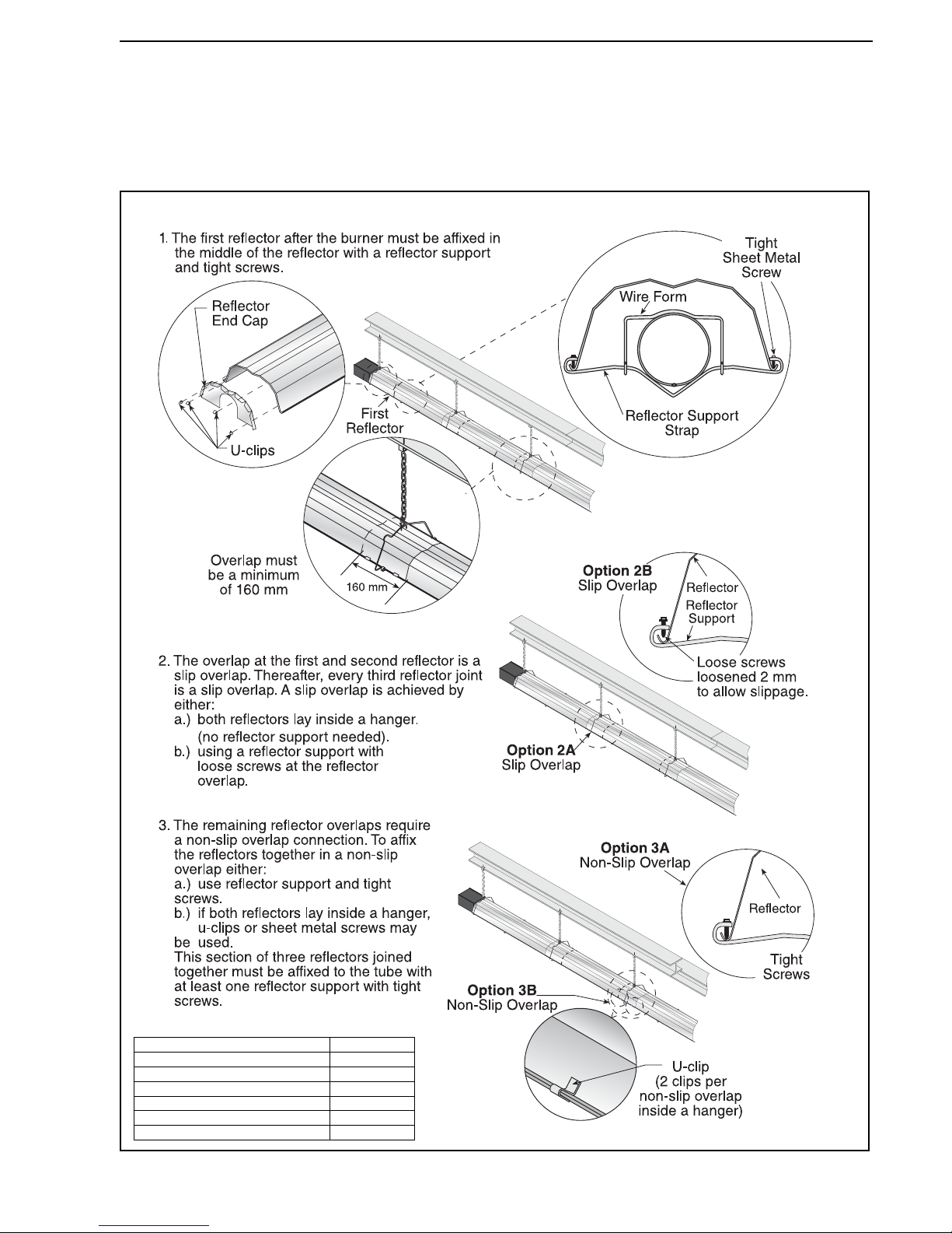
Step 6.6.1 Reflector, U-clip and Reflector Support Installation
The pictorial drawings of the heater construction in
Section 6 are schematic only and provide a general
guideline of where hangers, reflector supports and
u-clips are to be installed.
To ensure proper expansion and contraction movement of
the reflectors, a combination of u-clips and reflector
supports are used. The positioning of reflector supports
and u-clips depend on the individual installation. Use
either pop rivets or sheet metal screws instead of u-clips
when installing end caps and joint pieces in areas where
impact and high wind may be a factor. The following rules
must be observed:
Description Part Number
Reflector Support Package 03050010
Wire Form 91908004
Reflector Support Strap 03050000
Screw #8 x 3/4 94320812
U-clip Package 91107720
Reflector End Cap 027508XX
Page 30
BLACKHEAT® HE INSTALLATION OPERATION AND SERVICE MANUAL
24 of 73
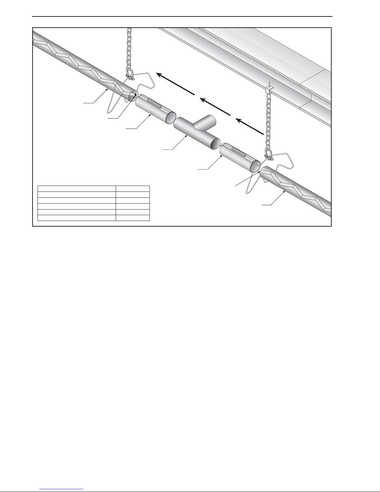
Step 6.7 Double Linear Tee Installation (For Double Linear Heaters Only)
Te e
Coupling
Coupling
Fan Tube
Fan Tube
Weld Spot
Weld Spot
Description Part Number
Tee 01330203
Fan Tube S51XXW
Coupling 01329600
Slide Bar/Coupling Lock 01329700
Tube/Reflector Hanger 03090100
Page 31
SECTION 7: U-TUBE HEATER INSTALLATION
25 of 73
SECTION 7: U-TUBE HEATER INSTALLATION
The figures in this section provide a general overview of
component placement in a u-tube system. The location of
some components such as supports and couplings is
crucial for proper installation. Assemble the heater
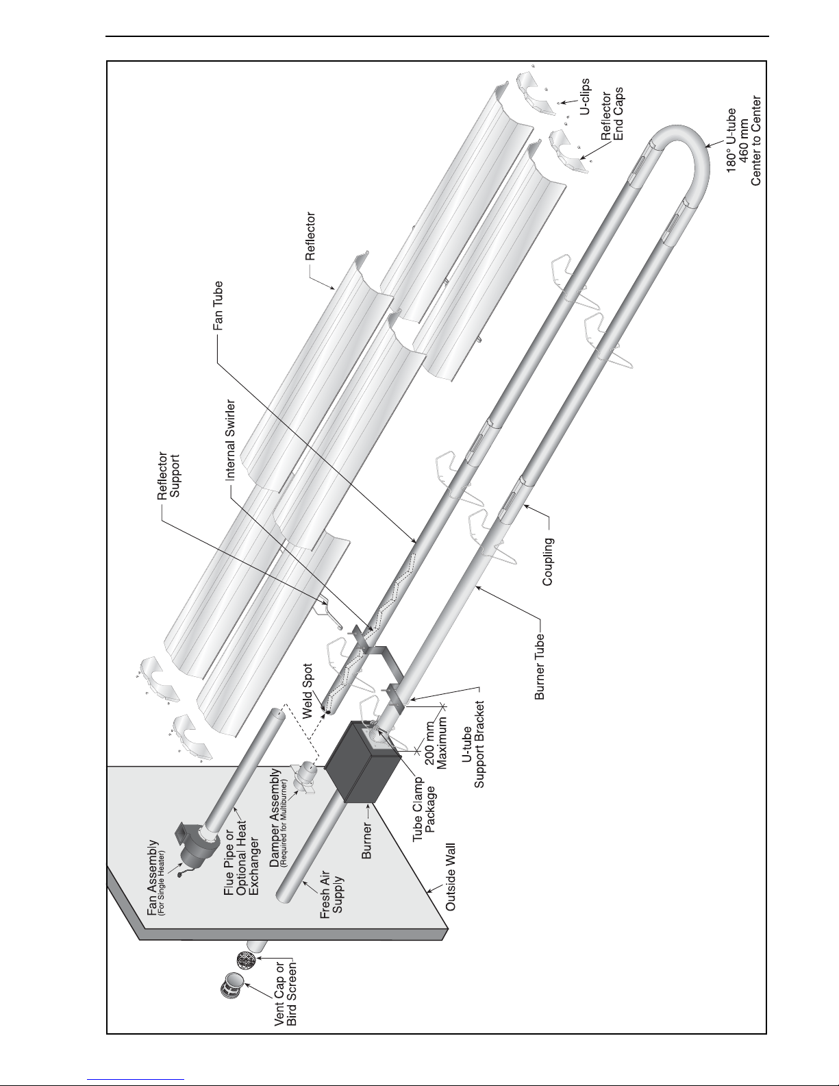
components as shown on Page 27, Figure 22.
For optional reflector configurations for u-tube heaters,
see Page 8, Figure 10 through Page 9, Figure 16. Install
appropriate suspension hardware, beam clamps, chain or
rod at predetermined locations. Adjustments of chain
length will provide uniform pitch.
If any step is unclear, please contact Roberts-Gordon
Europe Limited at +44 (0)121 506 7700.
7.1 U-tube Standard Parts List
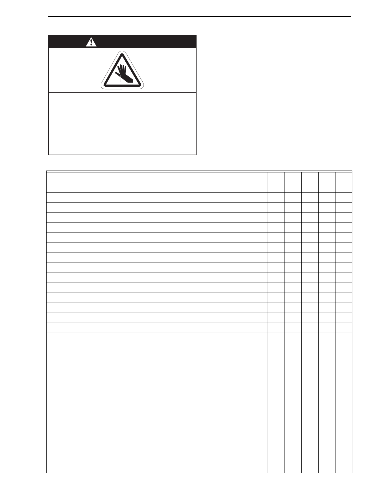
WARNING
Cut/Pinch Hazard
Wear protective gear during installation,
operation and service.
Edges are sharp.
Failure to follow these instructions can result
in injury.
Part No. Description
HE15UT
HE20UT
HE25UT
HE30UT
HE35UT
HE40UT
HE45UT
HE50UT
033XXXXX Burner Assembly (Input and Fuel Varies) 1 1 111111
07260053 Fan Package 3 IP55 1 1 111111
03360115Restrictor Plate BH HE 15 1-------
03360120Restrictor Plate BH HE 20 -1------
03360125Restrictor Plate BH HE 25 --1-----
03360130 Restrictor Plate BH HE 30 - - - 1 - - - -
03360135 Restrictor Plate BH HE 35 - - - - 1 - - -
03051600Burner Tube, 100 mm x 3048 mm 11111111
91409408Tube, 100 mm x 3048 mm - - -22222
91409423 Tube, 100 mm x 1524 mm - 2 2 - - - 2 2
S5127WFan Tube, 100 mm x 3048 mm, with 3048 mm Swirler -1111111
S5134WFan Tube, 100 mm x 3048 mm, with 2134 mm Swirler 1-------
01335901U-tube 11111111
01329600Standard Coupling Assembly 24444466
01329700Coupling Lock 24444466
02750303Reflector, Aluminium, 2439 mm 44466688
027503SS Reflector, Stainless Steel, 2439 mm (Optional)* 4 4 466688
02750800Reflector End Cap, Aluminium 44444444
027508SHReflector End Cap, Stainless (Optional)* 44444444
03090100Tube and Reflector Hanger 46666688
01318901 Tube Clamp Package (including Nut, Washer & Bolt) 1 1 111111
91908004Wire Form 24444466
03050000Reflector Support Strap 24444466
03020501 U-tube Support Bracket 1 1 111111
E0007576Bow Shackle** 46666688
91107720 U-clip Package (20 Pieces) 2 2 222222
91912501U-bolt M6 22222222
C0090BNut M6 66666666
Page 32
BLACKHEAT® HE INSTALLATION OPERATION AND SERVICE MANUAL
26 of 73
*PVC coating must be removed prior to installation.
**Some models may receive S-hooks (P/N 91907302) or
spring hooks (P/N 91903300), rather than bow shackles.
96411500Lockwasher 6mm 66666666
94320812Screw #8 x 3/4, (Goes with 03050000) 4888881212
S7199K Damper Flange Assembly (For use on Multiburner Systems) 1 Per Heater
Page 33
SECTION 7: U-TUBE HEATER INSTALLATION
27 of 73
Figure 22: U-tube Assembly Overview
Page 34
BLACKHEAT® HE INSTALLATION OPERATION AND SERVICE MANUAL
28 of 73
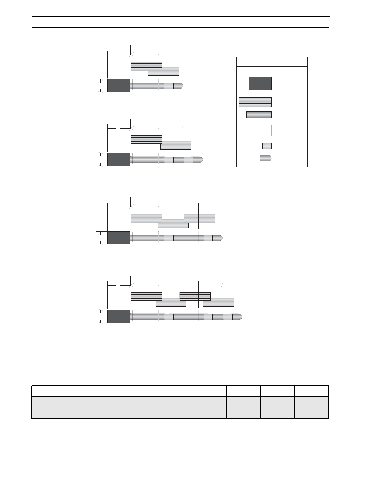
Figure 23: BLACKHEAT® HE U-tube Layout Overview
Model HE15UT HE20UT HE25UT HE30UT HE35UT HE40UT HE45UT HE50UT
Reflector
Overlap
(approx.)
1780 mm 250 mm 250 mm 580 mm 580 mm 580 mm 690 mm 690 mm
HE20UT
HE25UT
HE15UT
HE30UT
HE35UT
HE40UT
HE45UT
HE50UT
a = overall width (not shown) - 850 mm
b = end cap to burner/fan - 50 mm
c = end cap to hanger - 50 mm
d = distance first hanger - 2290 mm
e = distance typical between hangers - 3050 mm
f = distance between last full tube
hanger and half tube hanger - 1900 mm
g = burner height - 241 mm
h = burner length - 445 mm
U-Tube
Burner
Reflector
Tube
Tube/Reflector
Hanger
Coupling
Assembly
LEGEND
h
c
b
d
g
c
b
d
f
c
b
de
c
b
de
f
h
g
h
g
h
g
Page 35
SECTION 7: U-TUBE HEATER INSTALLATION
29 of 73
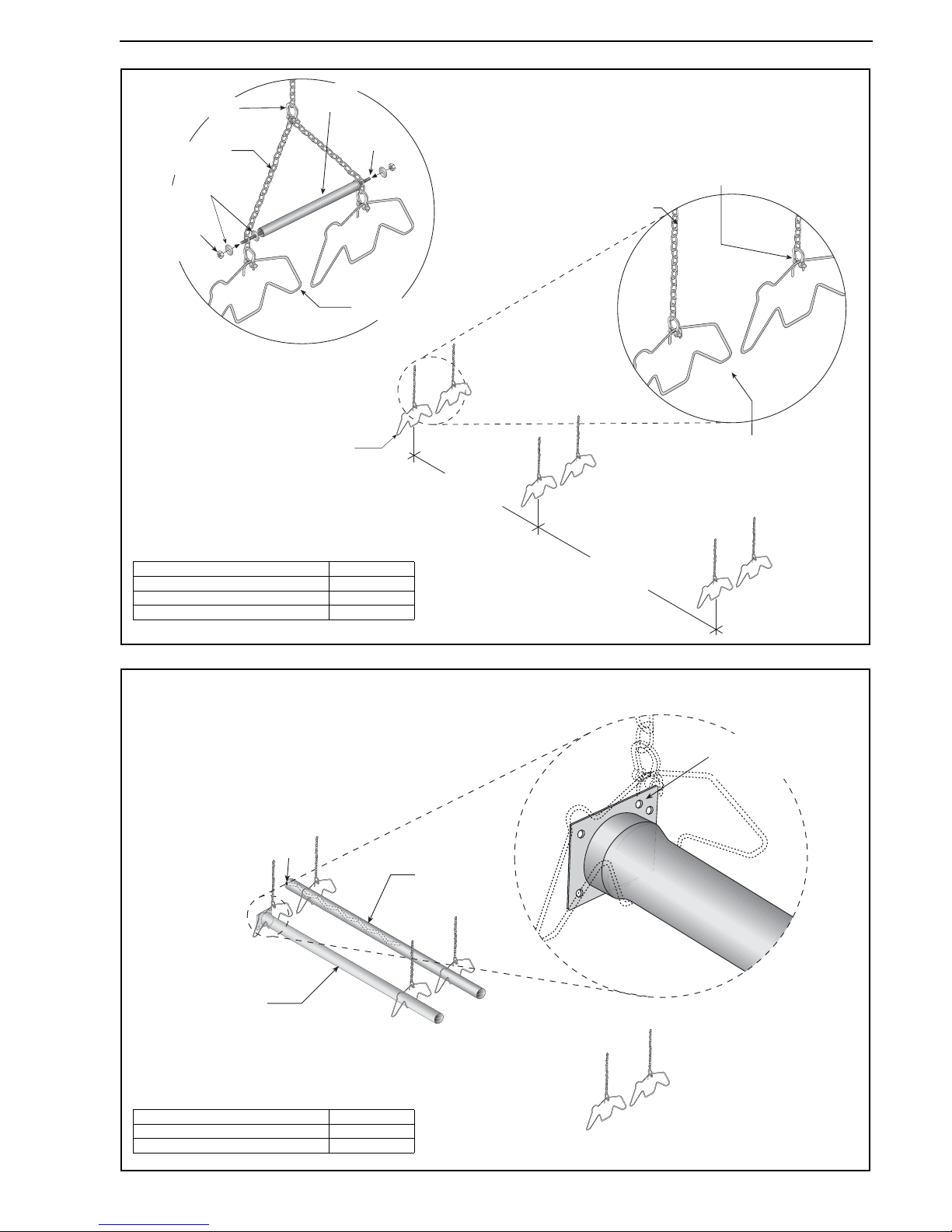
Step 7.2 U-tube Hanger Placement
Step 7.3 Burner Tube and Fan Tube Installation
2290 mm ± 250 mm
See Assembly
Drawing
First Tube and
Reflector Hanger
Bow
Shackle
Tube and Reflector
Hanger
Suspension
Chain
Optional
Hanging
Configuration
Washers
Bolt
(Torque:
13.5 Nm
129 in lb)
Bow
Shackle
NOTE: Spreader bar must be used on
single suspension point installations.
Do not hang heater from spreader bar.
Threaded
Bar
Tube and Reflector
Hanger
Suspension
Chain
Spreader
Bar
Description Part Number
Bow Shackle E0007576
Tube/Reflector Hanger 03090100
Spreader Bar 07260010
Fan Tube
Burner Tube
Weld seam
must be to the
bottom of the tube.
Offset mounting
hole must be
to the top.
Weld
Spot
Description Part Number
Burner Tube 03051600
Fan Tube S5127W
Page 36
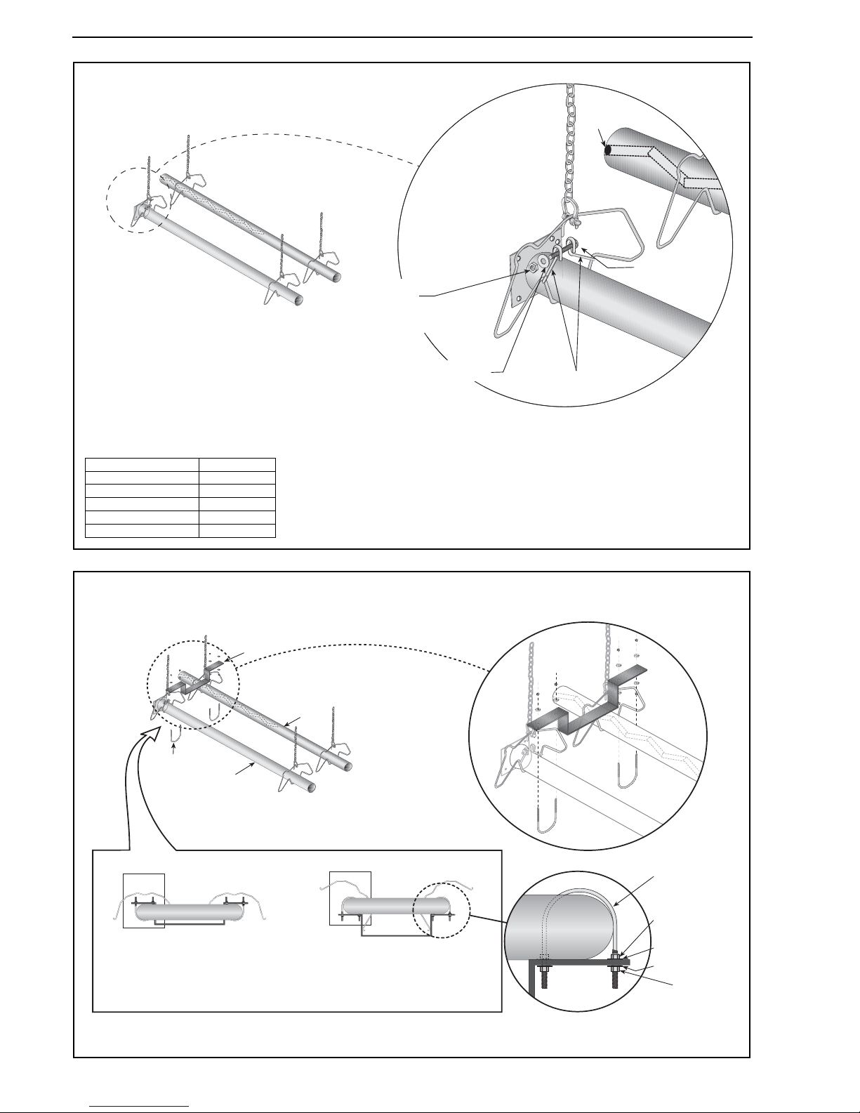
BLACKHEAT® HE INSTALLATION OPERATION AND SERVICE MANUAL
30 of 73
Step 7.3.1 Tube Clamp Package Installation
Step 7.4 U-tube Support Bracket Assembly Installation
Tube Clamp
Bolt
Lock Washer
Nut
(Torque: 13.56 Nm
120 in lb)
Weld
Spot
Description Part Number
Tube Clamp Package01318901
Tube Clamp 01396801
Bolt 97113940
Flat Washer 95211600
Nut 92113900
Note: Tube clamp package should be
installed 100 mm from burner tube plate.
Other hangers do not need tube clamp
packages.
Tight
U-bolt
100 mm u-bolt,
secured to burner tube
with M6 lockwashers
and M6 nuts.
TIGHT.
Loose
U-bolt
100 mm u-bolt,
secured to bracket
with M6 lockwashers
and M6 nuts on top and
bottom to allow for tube
expansion and contraction.
U-tube, Standard U-tube, Opposite 45°
Tight
U-bolt
100 mm u-bolt,
secured to burner tube
with M6 lockwashers
and M6 nuts.
TIGHT.
Loose
U-bolt
100 mm u-bolt,
secured to bracket
with M6 lockwashers
and M6 nuts on top and
bottom to allow for tube
expansion and contraction.
Nut (Torque:
90 in lb
10.2 Nm)
Lock Washer
Lock Washer
U-bolt
Fan Tube
Burner
Tube
U-bolt
Tight to
Tube
U-bolt
Tight to
Bracket
Nut
(Torque: 90 in lb
10.2 Nm)
Page 37
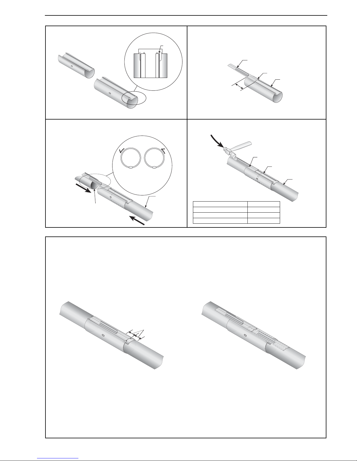
SECTION 7: U-TUBE HEATER INSTALLATION
31 of 73
Step 7.5 Coupling and Tube Assembly
Step 7.5.1 Coupling and Tube Assembly (Continued)
Tube
Tube
Orient coupling so that
the impact block is in the
2:00 or 10:00 oclock
positions
Closed
Open
Ta b
76 mm to
101 mm
Slide Bar
Coupling
Wide End
Coupling
Tube
Slide Bar
A
Close coupling
with tab
B
Start slide bar/coupling lock
onto coupling
C
Insert tubes into coupling
D
Tighten coupling to join tubes
Description Part Number
Coupling 01329600
Slide Bar/Coupling Lock 01329700
Tube 91409408
Incorrect Slide Bar
position
Correct Slide Bar
dimensions
± 50 mm
Drive slide bar until tight.
End of slide bar should be
within tolerance listed below.
• Repeat Step 7.5 A - D until all tubes are assembled.
Tighten slide bar as shown below.
Page 38
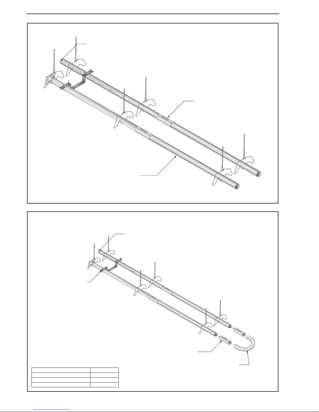
BLACKHEAT® HE INSTALLATION OPERATION AND SERVICE MANUAL
32 of 73
Step 7.6 Tube Installation
Step 7.7 U-tube Installation
Tube
Coupling
Weld Spot
Coupling
U-tube
U-tube Support
Bracket Assembly
Weld Spot
Description Part Number
Coupling 01329600
Slide Bar/Coupling Lock 01329700
U-tube 01335901
Page 39
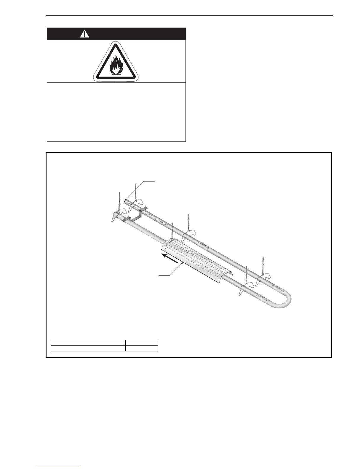
SECTION 7: U-TUBE HEATER INSTALLATION
33 of 73
Step 7.8 Reflector Installation
WARNING
Fire Hazard
Support reflector with reflector hanger
and support strap.
Reflector must not touch tube.
Failure to follow these instructions can result
in death, injury or property damage.
Reflector
Weld Spot
Description Part Number
Reflector 02750303
Page 40
BLACKHEAT® HE INSTALLATION OPERATION AND SERVICE MANUAL
34 of 73
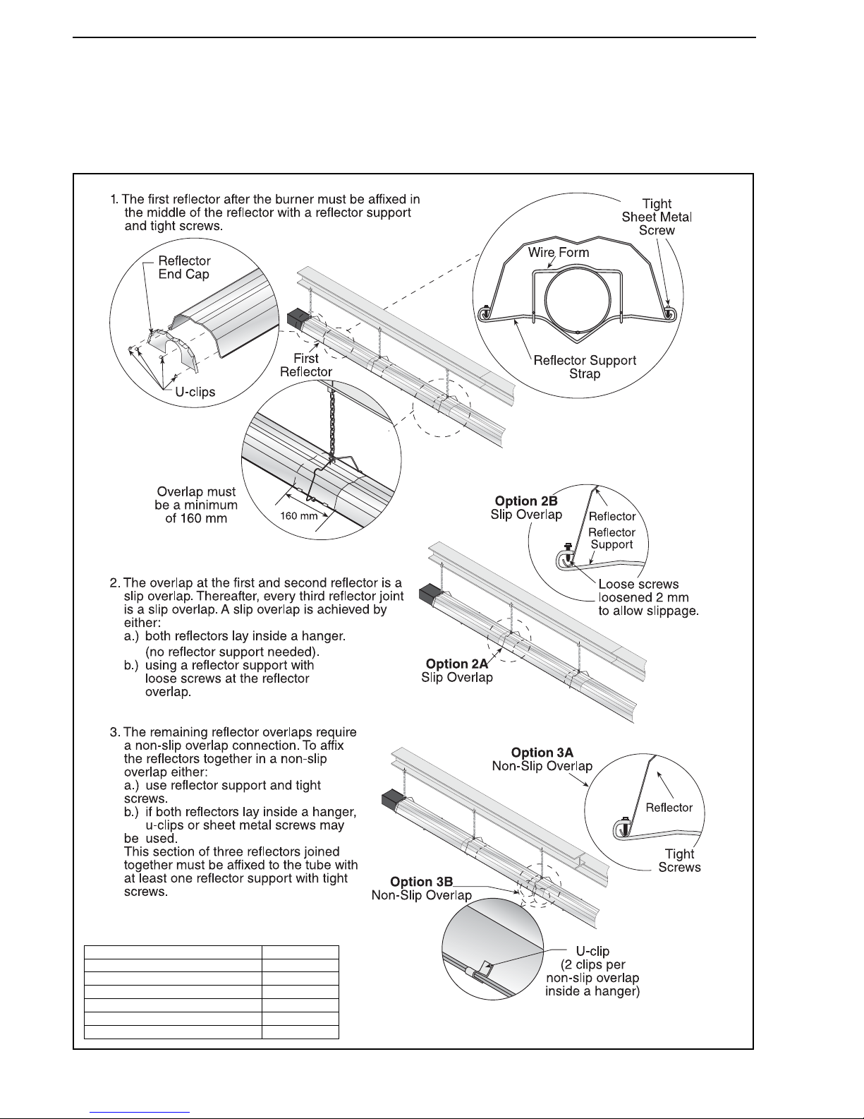
Step 7.8.1 Reflector, U-clip and Reflector Support Installation
The pictorial drawings of the heater construction in
Section 6 are schematic only and provide a general
guideline of where hangers, reflector supports and
u-clips are to be installed.
To ensure proper expansion and contraction movement of
the reflectors, a combination of u-clips and reflector
supports are used. The positioning of reflector supports
and u-clips depend on the individual installation. Use
either pop rivets or sheet metal screws instead of u-clips
when installing end caps and joint pieces in areas where
impact and high wind may be a factor. The following rules
must be observed:
Description Part Number
Reflector Support Package 03050010
Wire Form 91908004
Reflector Support Strap 03050000
Screw #8 x 3/4 94320812
U-clip Package 91107720
Reflector End Cap 027508XX
Page 41
SECTION 8: MULTIBURNER CONFIGURATION & INSTALLATION
35 of 73
SECTION 8: MULTIBURNER CONFIGURATION & INSTALLATION
8.1 Initial Assembly
See Page 13, Section 6 for linear heater assembly
instructions.
See Page 25, Section 7 for u-tube heater assembly
instructions.
Check layout drawings for location of manifold pipe
installation.
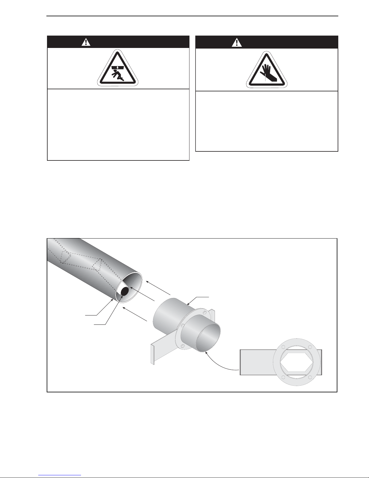
Figure 24: Multiburner Damper Flange Installation
WARNING
Severe Injury Hazard
Secure burner to burner tube with bolts and
lockwashers.
Hang heater with materials with a minimum
working load of 75 lbs (33 kg).
Failure to follow these instructions can result
in death, injury or property damage.
WARNING
Cut/Pinch Hazard
Wear protective gear during installation,
operation and service.
Edges are sharp.
Failure to follow these instructions can result
in injury.
Fan Tube
Damper Flange
Assembly
Note:
Install in the
fully open position
Weld Spot
Page 42
BLACKHEAT® HE INSTALLATION OPERATION AND SERVICE MANUAL
36 of 73
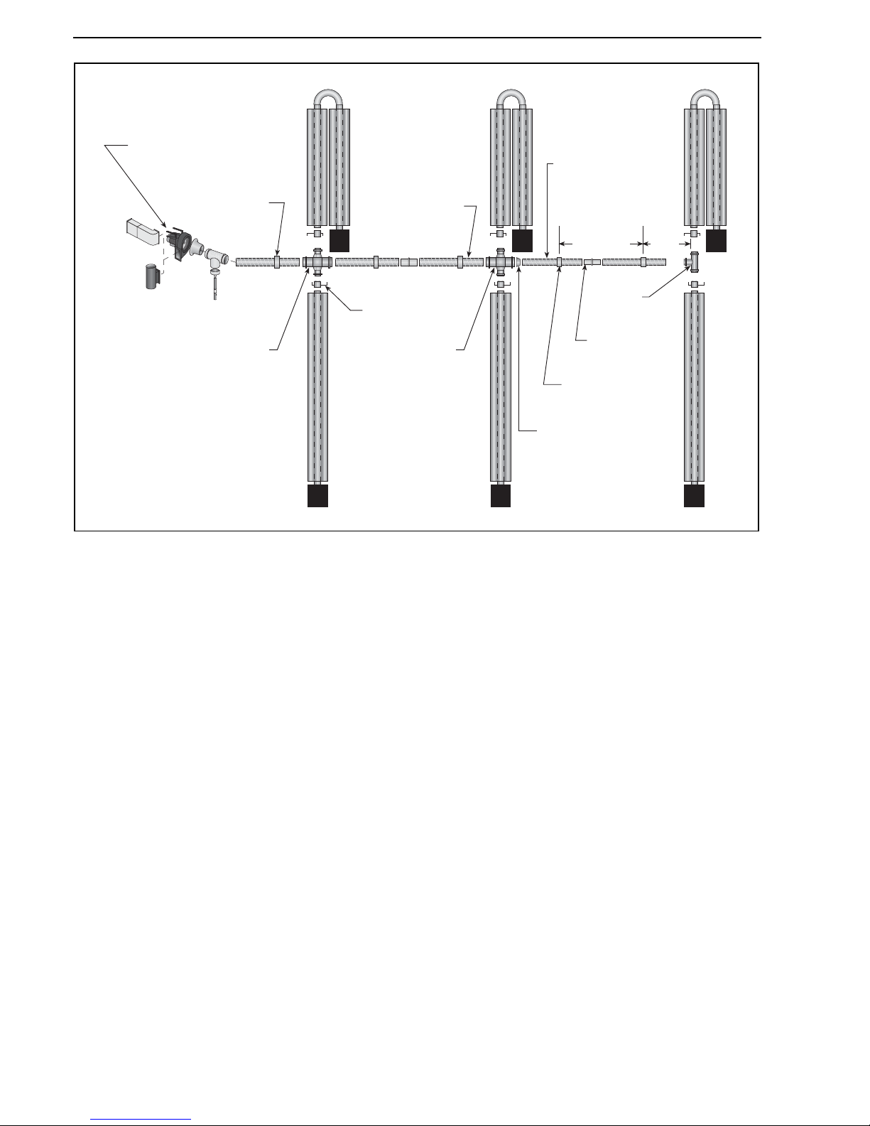
Figure 25: Typical Manifold Layout (Linear and U-Tube Configuration)
*Typical Fan
Arrangement
150 mm Hanger
150 mm Manifold
Damper (Typical)
Cross
(100 x 150 x 100 x 150)
100 mm Manifold
100 mm Hanger
ID/ID Sleeve
Te e
(100 x 100 x 100)
Cross
(100 x 150 x 100 x 150)
Max
3000 mm
HE25ST
HE25UT
HE25ST
HE25UT
HE25ST
HE25UT
NOTE: Be sure to
silicone seal all
manifold joints.
Reducer
(100 x 150)
Max
1000
mm
*Locate fan
away from wet
environment.
Page 43
SECTION 9: BURNER & FAN INSTALLATION
37 of 73
SECTION 9: BURNER & FAN INSTALLATION
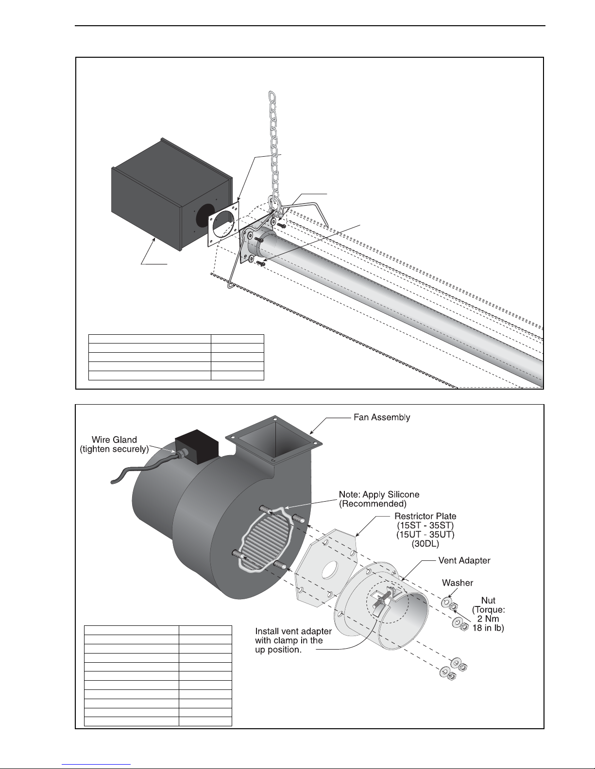
Step 9.1 Burner Installation
Step 9.2 IP55 Fan Assembly
Lock
Washer
Gasket
Bolt
(Torque:13.5 Nm
120 in lb)
Burner
Description Part Number
Bolt 93304507
Lock Washer 96411600
Gasket 02568200
Burner 033XXXXX
NOTE: Tube Clamp Package not shown for clarity.
For details, see Page 21, Step 6.5.
Description Part Number
Fan Assembly 07260053
Vent Adapter 90710601
Locknut 92321100
Bolt C0365B
Nut M6 C0090B
Washer M6 95204501
Washer Flat 95310800
Outlet Gasket 90710704
Inlet Gasket 90710203
Restrictor Plate 033601XX
Page 44
BLACKHEAT® HE INSTALLATION OPERATION AND SERVICE MANUAL
38 of 73
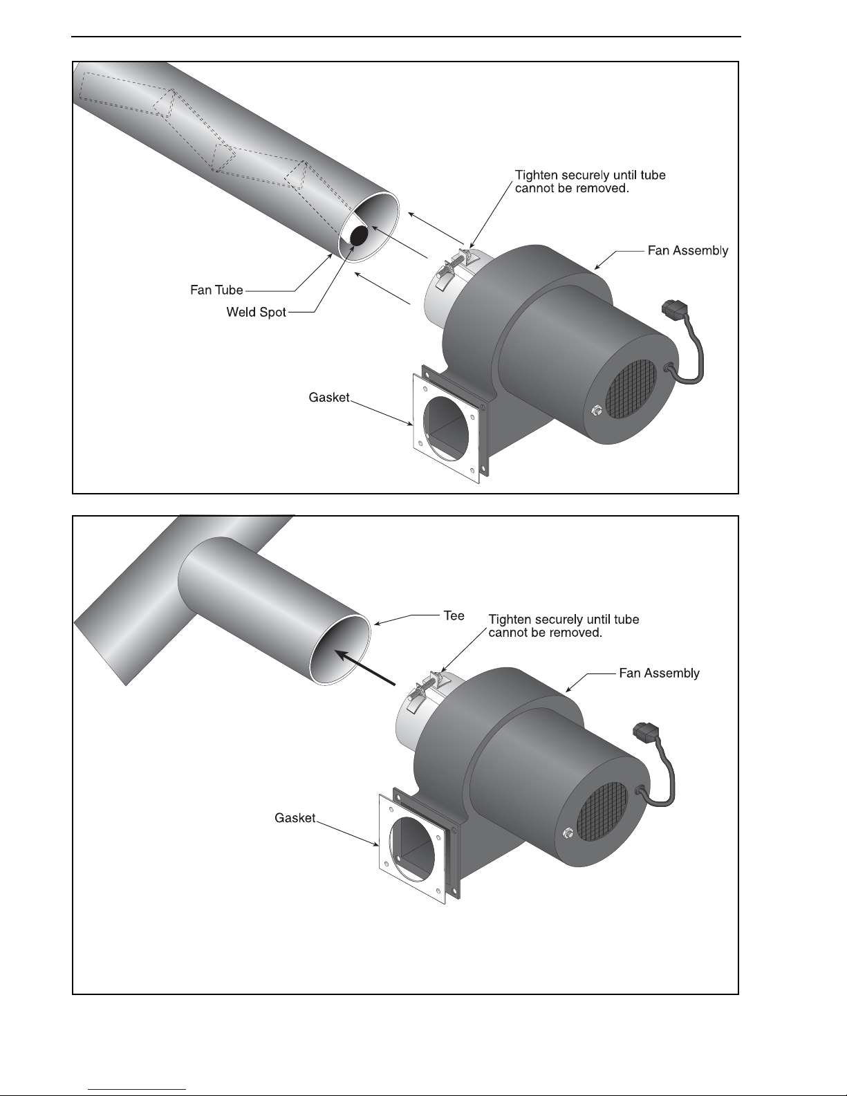
Step 9.3 Linear & U-tube Fan Installation
Step 9.4 Double Linear Fan Installation
Page 45
SECTION 9: BURNER & FAN INSTALLATION
39 of 73
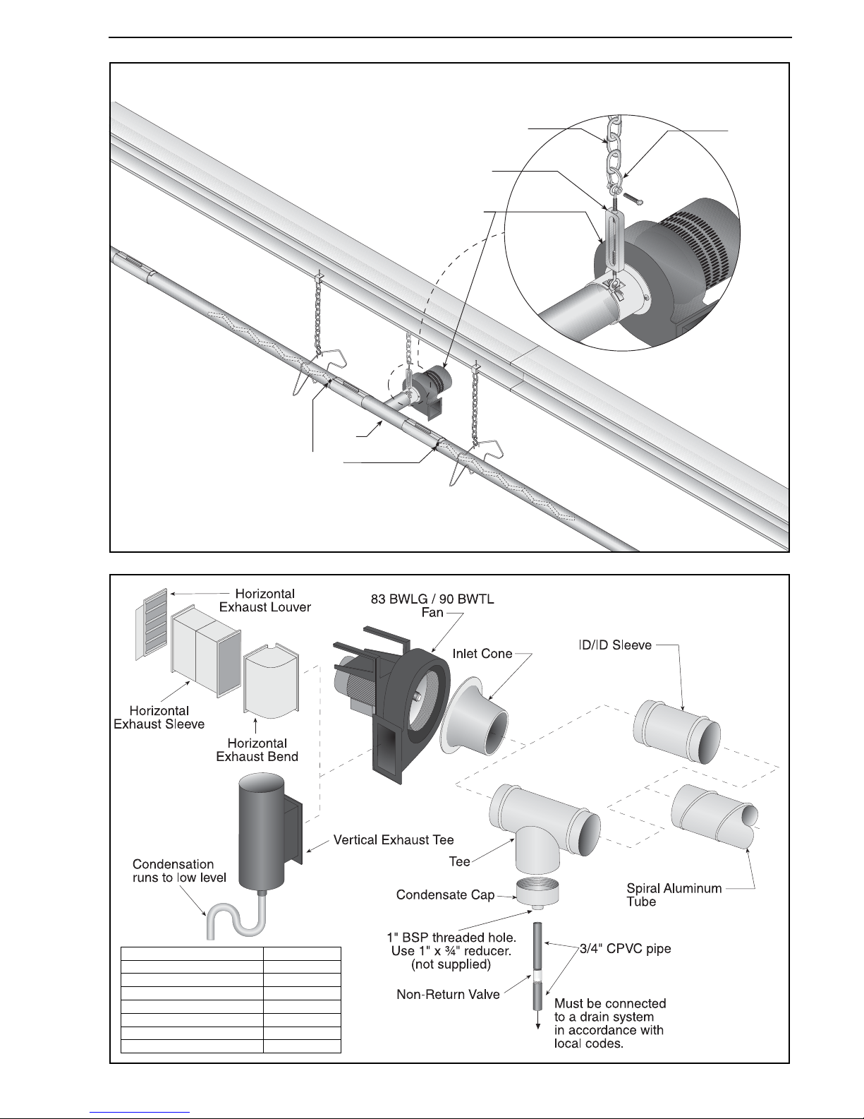
Step 9.4.1 Double Linear Fan Installation (Continued)
Step 9.5 Multiburner 83 BWLG/90 BWTL Fan Assembly (Horizontal and Vertical Outlets)
Fan Assembly
Height Adjuster
Bow
Shackle
Suspension Chain
Te e
Weld Spot
Description Part Number
Vertical Exhaust Tee C1324B
Horizontal Exhaust Bend C1325B
Horizontal Exhaust Sleeve C1326B
Horizontal Exhaust Louver S5055F
Condensate Cap 4" 02718851
Condensate Cap 6" 02718852
Non-Return Valve 90201200
Page 46
BLACKHEAT® HE INSTALLATION OPERATION AND SERVICE MANUAL
40 of 73
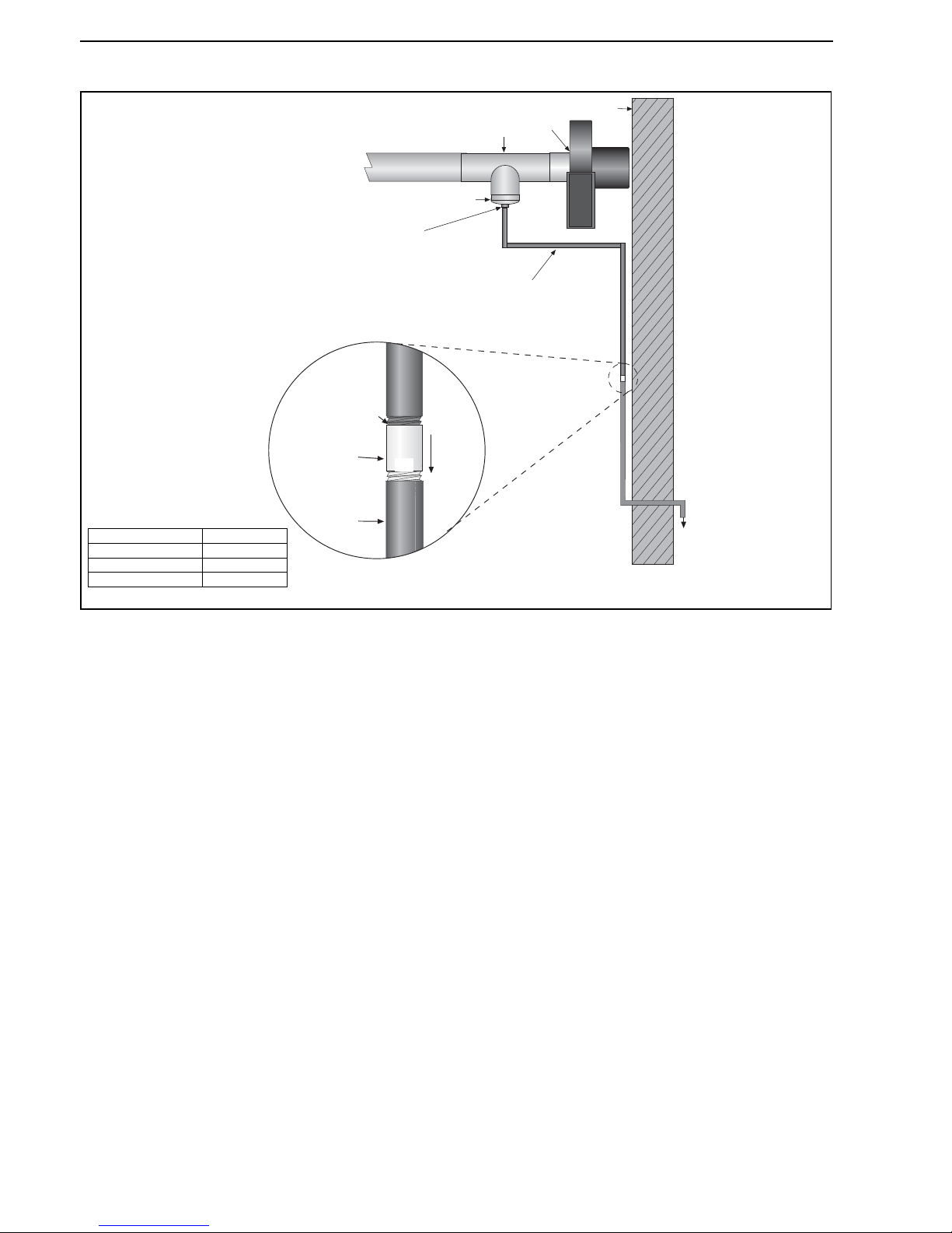
Step 9.6 Condensate Drain Assembly
Te e
Condensate Cap
Wall
1" BSP threaded hole.
Use 1" x ¾" reducer.
(not supplied)
Must be connected
to a drain system
in accordance with
local codes.
3/4" CPVC Pipe
Flow
Non-Return
Valve
3/4" CPVC
Pipe
3/4" Female
Fan
Description Part Number
Condensate Cap 4" 02718851
Condensate Cap 6" 02718852
Non-Return Valve 90201200
Page 47
SECTION 10: OPTIONAL HEATER ACCESSORIES
41 of 73
SECTION 10: OPTIONAL HEATER ACCESSORIES
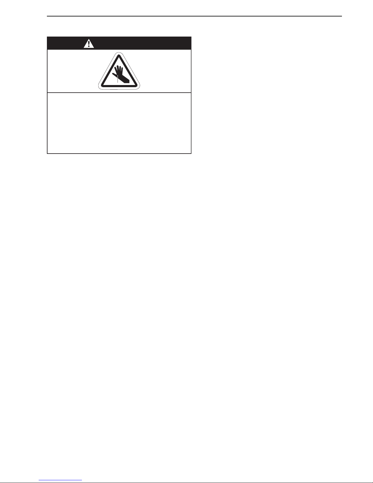
WARNING
Cut/Pinch Hazard
Wear protective gear during installation,
operation and service.
Edges are sharp.
Failure to follow these instructions can result
in injury.
Page 48
BLACKHEAT® HE INSTALLATION OPERATION AND SERVICE MANUAL
42 of 73
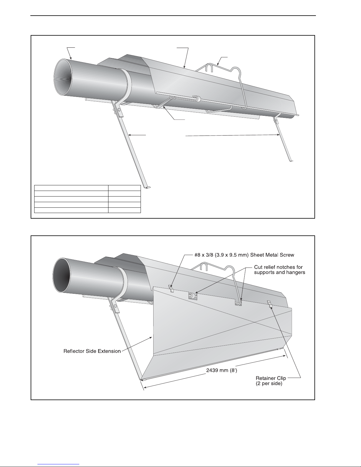
10.1 Reflector Side Extension Installation
Step 10.1.1 Bracket Installation
Step 10.1.2 Side Reflector Installation
Reflector Side
Extension Bracket
(2 per reflector)
Use additional supports
in high air movement
applications.
Tube and Reflector Hanger
Reflector
Tube
Reflector Support
Description Part Number
Reflector Side Extension Package S7377K
Reflector Side Extension 01368000
Retainer Clips 02751200
Reflector Side Extension Bracket 01329910
Page 49
SECTION 10: OPTIONAL HEATER ACCESSORIES
43 of 73
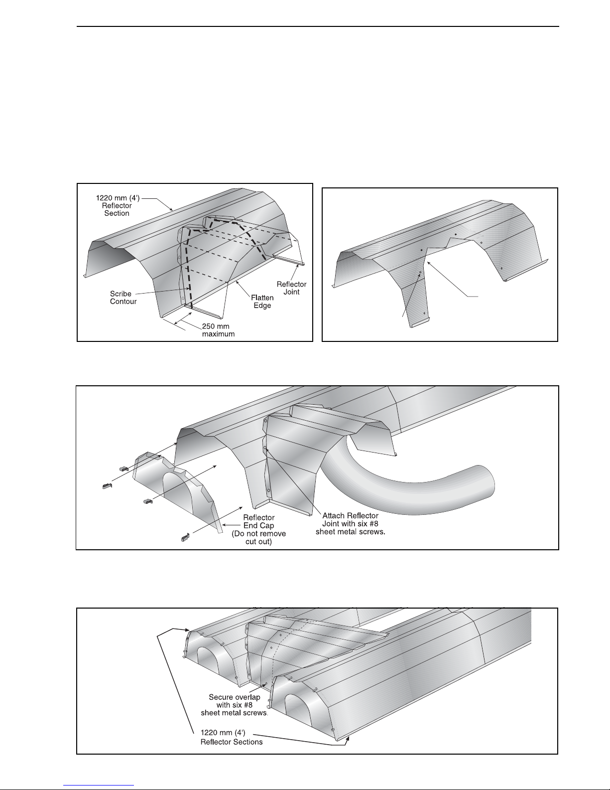
10.2 U-Tube Cover Installation
The package contains two reflector joint pieces (P/N 02750901), one 2439 mm (8') reflector and 18 x #8 sheet metal
screws. Install the u-tube cover using the following procedure.
Step 10.2.1
Cut the 2439 mm (8') reflector in half to be used on both
sides to cover the u-tube.
Step 10.2.2
Flatten 1220 mm (4') reflector edge where joint piece
matches. Put a mark on the 1220 mm (4') reflector,
directly over the tube center. Center the accessory joint
piece on the mark and scribe its contour on the reflector.
Scribe the location of the mounting holes.
Step 10.2.3
Cut away the reflector to clear the tube, leaving about 25
mm of material inside the scribed contour to attach the
accessory joint. Drill or punch six 3 mm diameter holes in
reflector in the positions shown below.
Step 10.2.4
Use six #8 sheet metal screws to attach the joint piece.
Repeat Steps 10.2.1 through 10.2.4 to attach the reflector joint piece on the other reflector.
Step 10.2.5
The overlap of both reflector joint pieces is attached with six #8 sheet metal screws.
Cut away contour
with tin snips.
Punch/Drill six
3 mm holes
Page 50
BLACKHEAT® HE INSTALLATION OPERATION AND SERVICE MANUAL
44 of 73
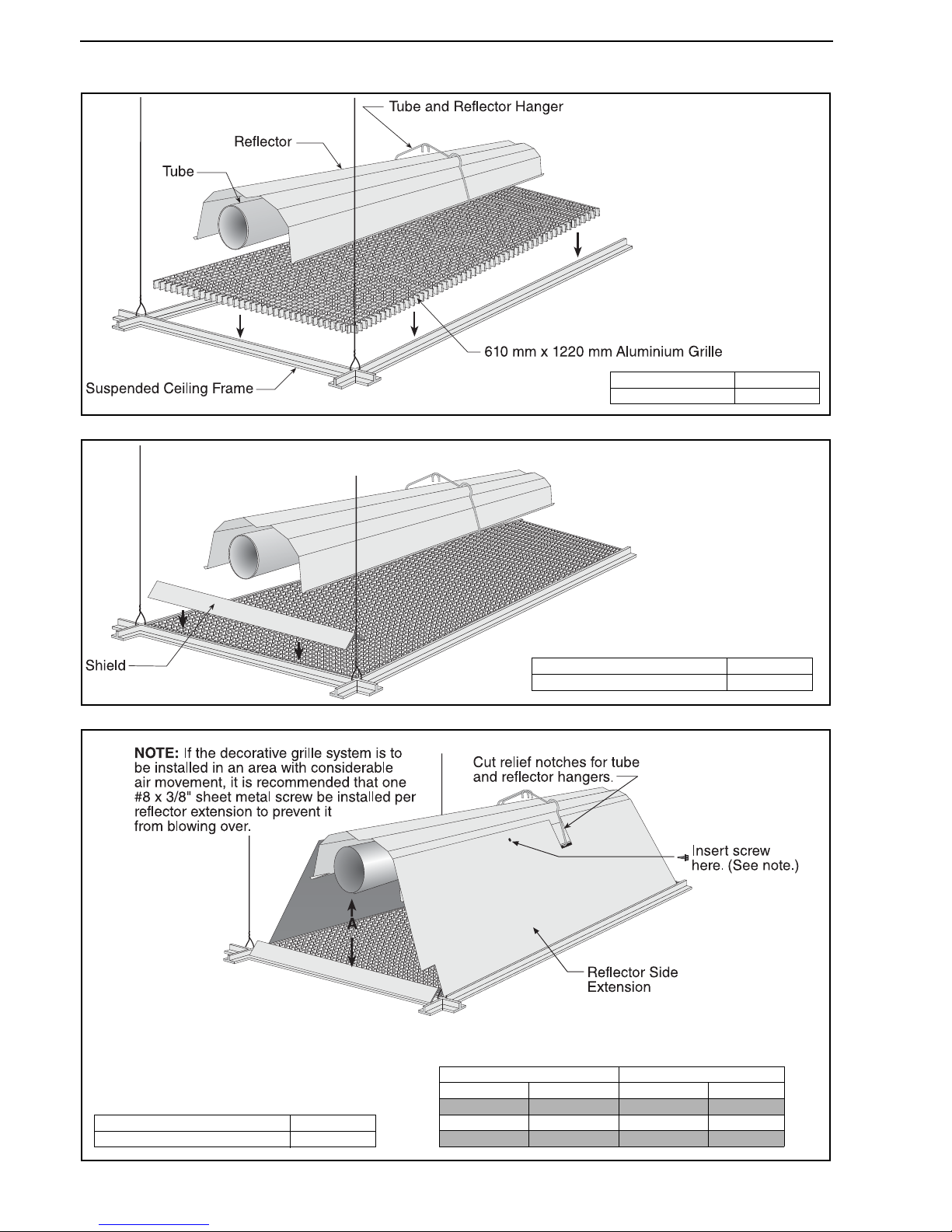
10.3 Decorative Grille Installation
Step 10.3.1 Grille Installation
Step 10.3.2 Frame Shield Installation
Step 10.3.3 Reflector Side Extension Installation for Decorative Grilles
Description Part Number
Aluminium Grille 91407000
Description Part Number
Deco Grille Shield 01365900
Distance "A" Extension
Minimum Maximum Part No. Width
40 mm 150 mm 01370408 200 mm
150 mm 260 mm 01370412 300 mm
260 mm 370 mm 01370416 400 mm
Description Part Number
Reflector Side Extension 01370412
Page 51
SECTION 10: OPTIONAL HEATER ACCESSORIES
45 of 73
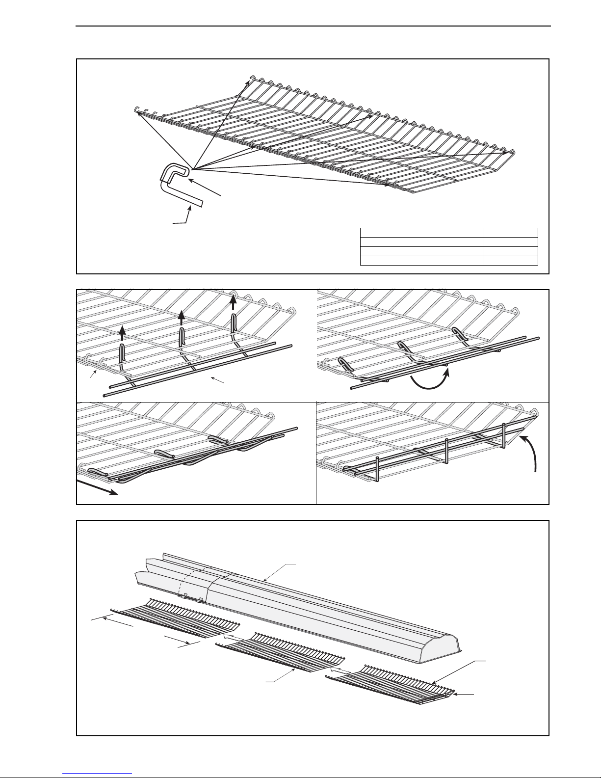
10.4 Protective Grille Installation
Step 10.4.1 Silicone Cap Installation
Step 10.4.2 Grille End Cap Installation
Step 10.4.3 Grille Installation
Silicone Cap
Grille
Finger
Description Part Number
Grille Section 08050001
Grille End Cap 08050002
Silicone Cap 91915951-6P
Bend up 90°.
Pull outward.
Grille
Grille End Cap
AB
CD
Grille
Grille
End Cap
Reflector
Final Grille
Section
1010 mm
Page 52
BLACKHEAT® HE INSTALLATION OPERATION AND SERVICE MANUAL
46 of 73
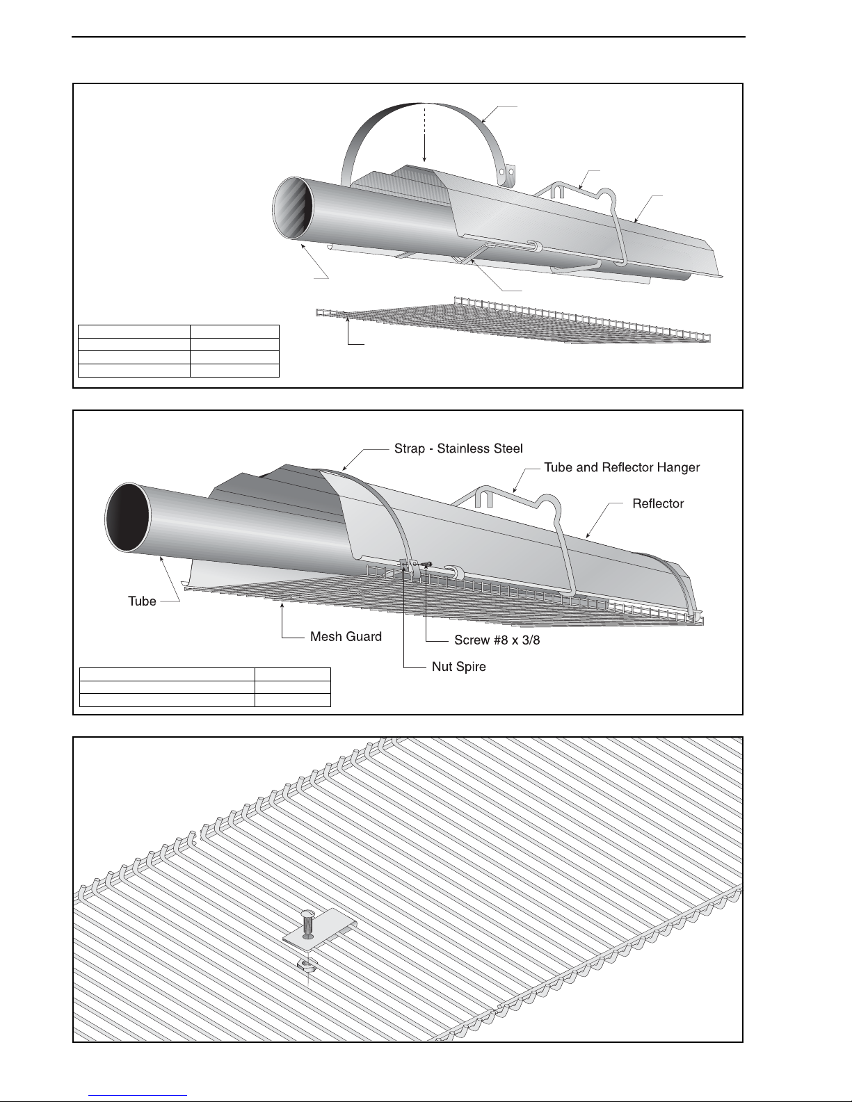
10.5 Sports Hall Guard Installation
Step 10.5.1 Grille Installation
Step 10.5.2 Fastener Installation
Step 10.5.3 Mesh Guard Connection
Tube and
Reflector Hanger
Reflector
Tube
Reflector Support
Strap - Stainless Steel
Mesh Guard
Description Part Number
Mesh Guard 2438 mm E0009855
Mesh Guard 1524 mm C2329B
Strap Stainless Steel S5218W
Description Part Number
Nut Spire C1088B
Screw #8 x 3/8 C1089B
Page 53
SECTION 10: OPTIONAL HEATER ACCESSORIES
47 of 73
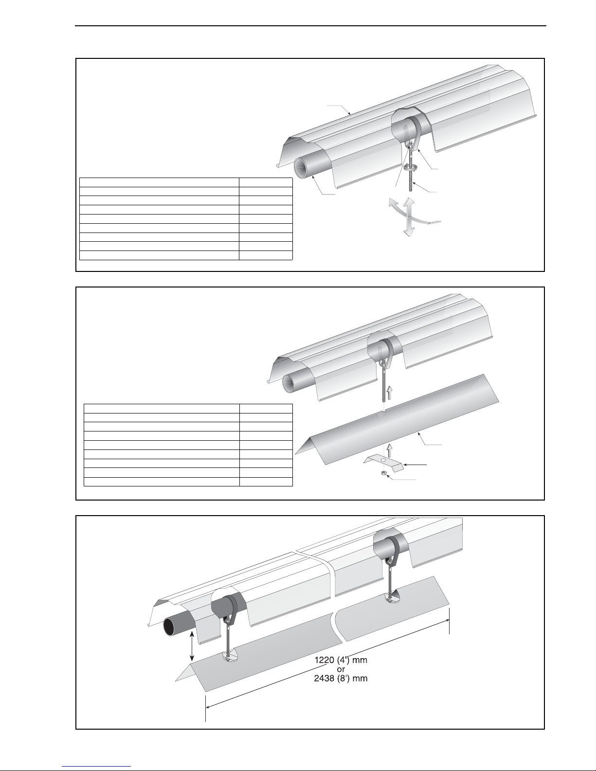
10.6 Undershield Installation
10.6.1 Hanger Installation
10.6.2 Undershield Installation
10.6.3 Adjust Undershield Height
Reflector
Tube
Assembly Hanging Bracket
Stud
Hex Nut
Description Part Number
Undershield Reflector Package 1220 mm (4') S7399K
Assembly Hanging Bracket C0318B
Stud M6 x 90 C0693B
Nut M6 C0090B
Undershield Reflector Package 2438 mm (8') S7399A
Assembly Hanging Bracket C0318B
Stud M6 x 90 C0693B
Nut M6 C0090B
Undershield Reflector
Hex Nut
Shield Support Bracket
Description Part Number
Undershield Reflector Package 1220 mm (4') S7399K
Undershield Reflector 1220 mm (4') C0521B
Nut M6 C0090B
Shield Support Bracket 02751700
Undershield Reflector Package 2438 mm (8') S7399A
Undershield Reflector 2438 mm (8') R1299B
Nut M6 C0090B
Shield Support Bracket 02751700
Page 54
BLACKHEAT® HE INSTALLATION OPERATION AND SERVICE MANUAL
48 of 73
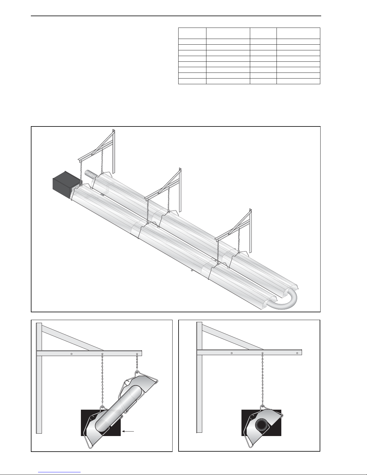
10.7 Wall Mounting
Install wall mounting brackets at the height shown in the
layout drawing provided by the estimator. Space wall
mounting brackets and hangers as indicated by
dimensions d, e and f in the relevant Layout Overview
drawing for your heater. For Linear heaters see Page 15,
Figure 19, for Double Linear heaters see Page 18, Figure
21 and for u-tube heaters see Page 28, Figure 23.
10.7.1 Hardware Installation
The wall mounting brackets must be attached to a
suitable wall through all mounting holes. Screw sizes less
than M8 (5/16") may not be used. In order for the wall
mounting brackets to adequately carry the weight of the
heater, it must be installed with best building practice.
Figure 26: U-tube (Horizontal)
Figure 27: U-tube (Angle Mounted) Figure 28: Linear
Model
Quantity of Wall
Mounting Brackets
Model
Quantity of Wall
Mounting Brackets
HE15UT 2 HE15ST 3
HE20UT 3 HE20ST 4
HE25UT 3 HE25ST 4
HE30UT 3 HE30ST 5
HE35UT 3 HE35ST 5
HE40UT 3 HE40ST 5
HE45UT 4 HE45ST 6
HE50UT 4 HE50ST 6
Burner must
be below fan
Page 55
SECTION 11: VENTING AND FRESH AIR SUPPLY
49 of 73
SECTION 11: VENTING AND FRESH AIR SUPPLY
11.1 General Venting
Flue materials are not included with the heater.
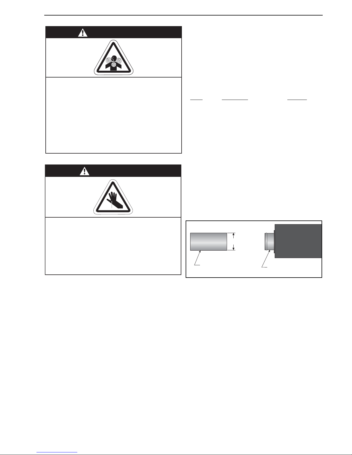
11.2 Type C12 , C32 & C62 Appliance
Room Sealed
The heaters are designed to be installed as room sealed
appliances. The flue and air intake are run as separate
pipes to the special concentric wall or roof terminal. See
Page 51, Figure 31.
11.3 Type B22 Appliance
The flue must be fitted with a low resistance terminal. See
Page 51, Figure 31.
11.4 Flue Installation
The fan outlet may discharge vertically or horizontally.
Connection should be made using 100 mm minimum
diameter Aluminium or Stainless Steel flue material to
National Standard and must be adapted to insert into the
100 mm flue adapter. Both fresh air supply and flue duct
shall not exceed 10,000 mm. HE15 and HE20 flue must
be insulated if longer than 5,000 mm. HE25 flue must be
insulated if longer than 8,000 mm. For each 90° bend,
subtract 1,000 mm from the maximum flue length. The
flue must be self supporting. Suitable terminals must be
fitted for horizontal and vertical flue.
In order to locate fans that are not IP54 protected away
from the wet environment, a 100 mm diameter extension
tube between the heat exchanger end and fan must be
installed. This length must be subtracted from the
maximum flue length.
Fans
Horizontal Vertical
83 BWLG 190 mm x 75 mm (hole) 150 mm dia.
90 BWTL 190 mm x 75 mm (hole) 150 mm dia.
11.5 Ventilation Requirements
Detailed recommendations for air supply are given in the
relevant National Standards. There must be an adequate
supply of air for both combustion and general ventilation.
Air vents should have negligible resistance. Do not locate
air vents where they can be easily blocked or flooded, or
adjacent to any flues or extraction systems carrying
flammable vapour.
11.6 Fresh Air Supply
The burner is equipped with a fresh air adapter which has
a silicone gasket incorporated. This adapter accepts
tubes with 100 mm outside diameter.
WARNING
Carbon Monoxide Hazard
Multiburner systems are not approved for
unvented use and must be vented outdoors.
Unitary heaters installed unvented must be
interlocked with sufficient building exhaust.
Heaters must be installed according to the
installation manual.
Failure to follow these instructions can result
in death or injury.
WARNING
Cut/Pinch Hazard
Wear protective gear during installation,
operation and service.
Edges are sharp.
Failure to follow these instructions can result
in injury.
Fresh Air Adapter
Fresh Air
Supply Duct
100 mm OD
Page 56
BLACKHEAT® HE INSTALLATION OPERATION AND SERVICE MANUAL
50 of 73
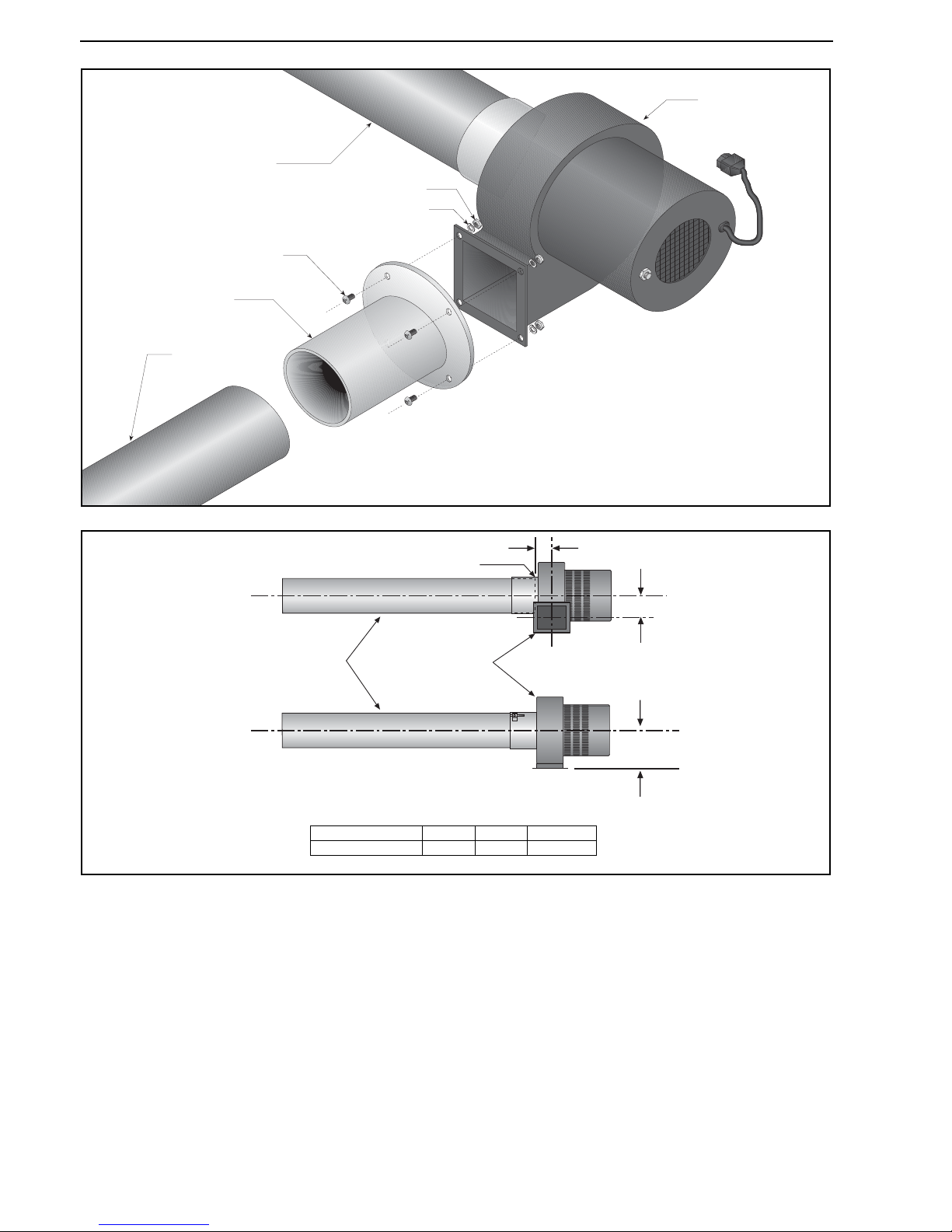
Figure 29: Individual Flue Connection Detail
Figure 30: Flue Connection Dimensions
11.7 Outside Combustion Air Supply
Clean air must be ducted into the burner box through the
100 mm diameter spigot on the back of the burner box.
See Page 49, Section 11.4 for recommendations on duct
length. Air duct should be as straight as possible. Consult
the manufacturer if more than 1 x 90° bend is necessary.
The fresh air duct must be self supporting.
11.7.1 Air Supply Requirements
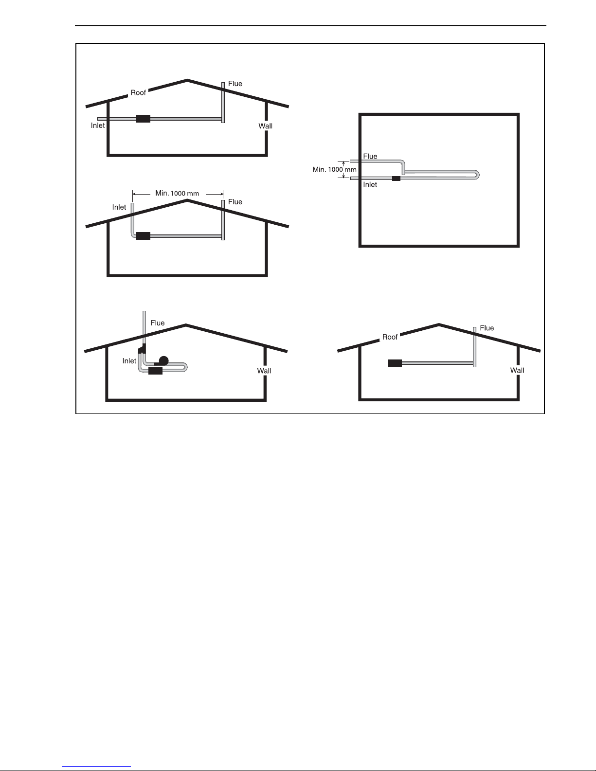
When fresh air duct is used, follow one of these rules:
• The flue must penetrate the roof while fresh air can
penetrate any wall. (See Page 51, Figure 31).
• The flue and fresh air supply must penetrate the roof
at a minimum of 1,000 mm apart.
(See Page 51, Figure 31).
• The flue must penetrate 1,000 mm higher than the
fresh air inlet on the same wall. (See Page 51, Figure
31).
Fan Tube
Flue Pipe
Flue Adapter
Fan Assembly
Screw
(Torque: 2 Nm
18 in lb)
Lockwasher
Nut
Fan Tube
Fan
A
B
C
End of Tube
Fan Part Number A B C
90710053 (IP55) 82 mm 101 mm 38 mm
Page 57
SECTION 11: VENTING AND FRESH AIR SUPPLY
51 of 73
Figure 31: Air Supply with Flue Configurations
11.8 Common Duct
When using a common air inlet duct, always ensure that
the area of the common air inlet duct represents the area
of all air ducts.
C
52
C
32
C12 C32 C
62
B
22
C
12
Page 58
BLACKHEAT® HE INSTALLATION OPERATION AND SERVICE MANUAL
52 of 73
SECTION 12: GAS PIPING
It is important that the gas supply pipe and electrical
connections do not support any of the heater’s weight.
Installation pipes should be fitted in accordance with
National Standards. Pipe work from the meter to the
heater(s) must be of adequate size. Pipes of smaller size
than the heater inlet gas connection should not be used.
Install the gas hose as shown on Page 53, Figure 32. The
gas hose accommodates expansion of the heating
system and allows for easy installation and service of the
burner. Before connecting the burners to the supply
system, verify that all high pressure testing of the gas
piping has been completed.
There is an expansion of the tube with each firing cycle.
This will cause the burner to move with respect to the gas
hose. This can cause a gas leak resulting in an unsafe
condition if the gas connection is not made in strict
accordance with Figu re 32.
Meter and service must be large enough to handle all the
burners being installed plus any other connected load.
The gas hose which feeds the system must be large
enough to supply the required gas with a maximum
pressure drop of 13 mm wc. When gas piping is not
included in the layout drawing, the local gas supplier will
usually help in planning the gas piping.
IMPORTANT - the complete installation must be tested
for gas soundness and be purged in accordance with
local and national codes.
• Check the pipe and tubing ends for leaks before
placing heating equipment into service. When
checking for gas leaks, use a soap and water
solution; never use an open flame.
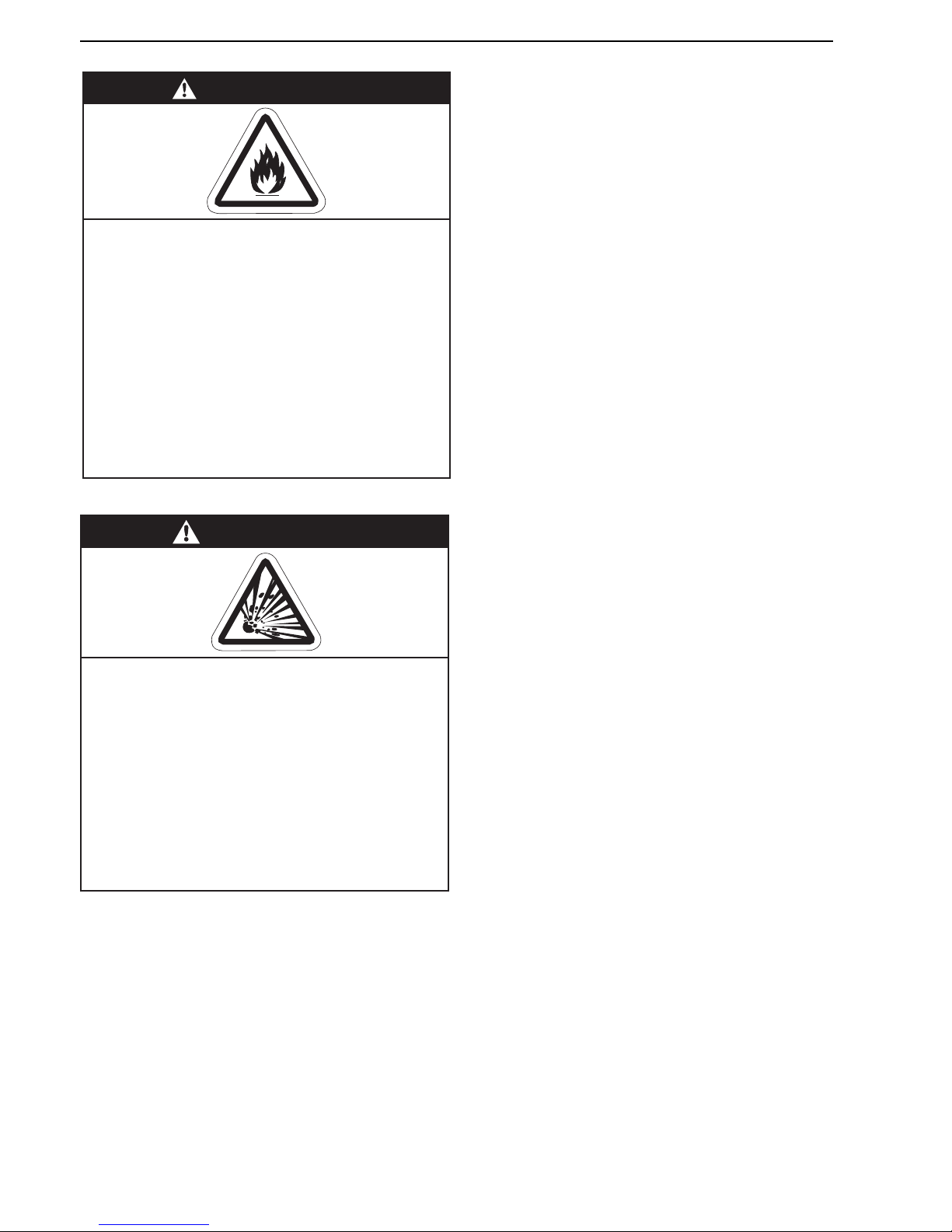
WARNING
Fire Hazard
Tighten gas line fittings to connect gas supply
according to Figure 32.
Flex gas line can crack when twisted.
Gas line moves during normal operation.
Use only 1000 mm long connector of 1/2" or
3/4" nominal ID.
Failure to follow these instructions can result
in death, injury or property damage.
WARNING
Explosion Hazard
Leak test all components of gas piping
before operation.
Gas can leak if piping is not installed
properly.
Do not high pressure test gas piping with
heater connected.
Failure to follow these instructions can result
in death, injury or property damage.
Page 59
SECTION 12: GAS PIPING
53 of 73
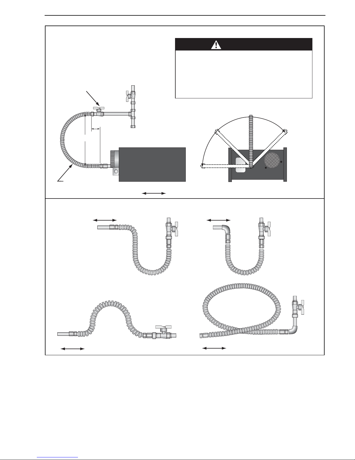
Figure 32: Gas Connection with Stainless Steel Flex Connector
Shut-Off Valve (included with gas hose) must
be parallel to burner gas inlet. The 80 mm
displacement shown is for the cold condition.
This displacement may reduce when the
system is fired.
CORRECT POSITIONS
Horizontal
45°
End View
Vertical
(as shown left)
Alternate
positions
okay
Flexible Gas Hose
910 mm length
80 mm)
max. displacement
Side View
Heater Movement
30 mm
CAUTION
Product Damage Hazard
Hold gas nipple securely with pipe wrench
when attaching gas hose.
Failure to follow these instructions can result
in product damage.
INCORRECT POSITIONS (WRONG INSTALLATION)
Heater Movement
Heater Movement
Heater Movement Heater Movement
Page 60
BLACKHEAT® HE INSTALLATION OPERATION AND SERVICE MANUAL
54 of 73
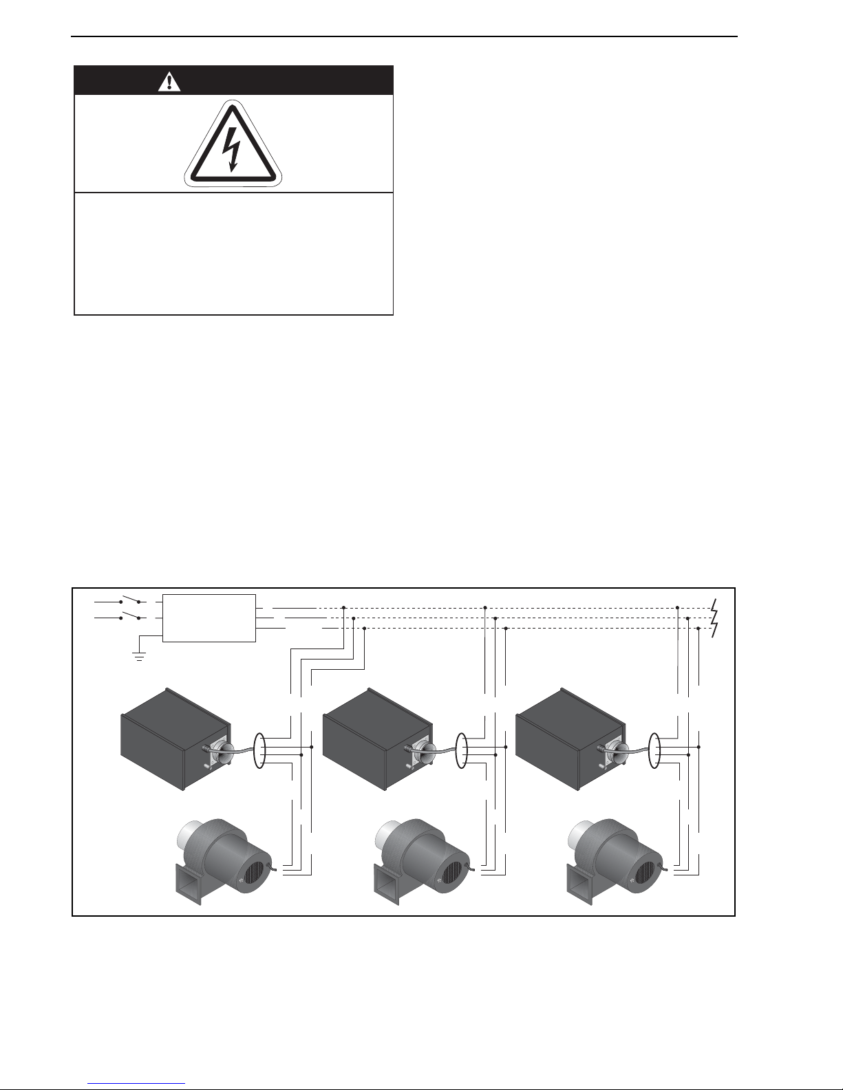
SECTION 13: WIRING
Connect to the electrical supply using the power wire
coming out of the wire gland via a locally mounted IP55
protected double pole fused switch having a minimum
disconnection of 3 mm on each pole. This switch should
be fused to 3 amps. There are no control connections in
the standard burner. Control is affected by interruption of
the main power inlet. See Page 54, Section 13.1 through
Page 55, Section 13.4 for the external wiring details for
the single-burner, double linear and multiburner heater
systems.
If the IP55 protected fan MB 56 2BM is used with a single
burner (linear or U-tube), it must be wired as shown on
Page 55, Section 13.2.
The fan must be protected with a 3 A fuse.
All wiring must comply with current wiring regulations and
any local regulations which may apply. Always switch off
the supply to the burner before removing the burner side
panel.
For lockout indication, establish connection inside burner
with grey wire and ignition module connection CON 5 Pin
4.
13.1 Typical External Wiring Diagram (Linear or U-Tube)
DANGER
Electrical Shock Hazard
Disconnect electric before service.
Heater must be properly grounded.
Failure to follow these instructions can result
in death or electrical shock.
Burner 1
Fan 1
Earth
Burner 2
Fan 2
Burner 3
Fan 3
Controller or
Thermostat
230 V
1 Ø
50 Hz
L
N
Earth
N
L
Blue
Green
Black
Blue
Brown
Green/Yellow
4 Wire Cable
{
Blue
Green
Black
Blue
Brown
Green/Yellow
4 Wire Cable
{
Blue
Green
Black
Blue
Brown
Green/Yellow
4 Wire Cable
{
Page 61

SECTION 13: WIRING
55 of 73
13.2 Typical External Wiring Diagram (Double Linear Option 1)
13.3 Typical External Wiring Diagram (Double Linear Option 2)
13.4 Typical External Wiring Diagram (Multiburner)
230 V
1 Ø
50 Hz
Burner 1
Burner 2
L
N
Earth
Earth
N
L
Fan
3 A
Fuse
Controller or
Thermostat
Controller or
Thermostat
Burner 1 Burner 2
L
N
Earth
Fan
Earth
N
L
230 V
1 Ø
50 Hz
Page 62
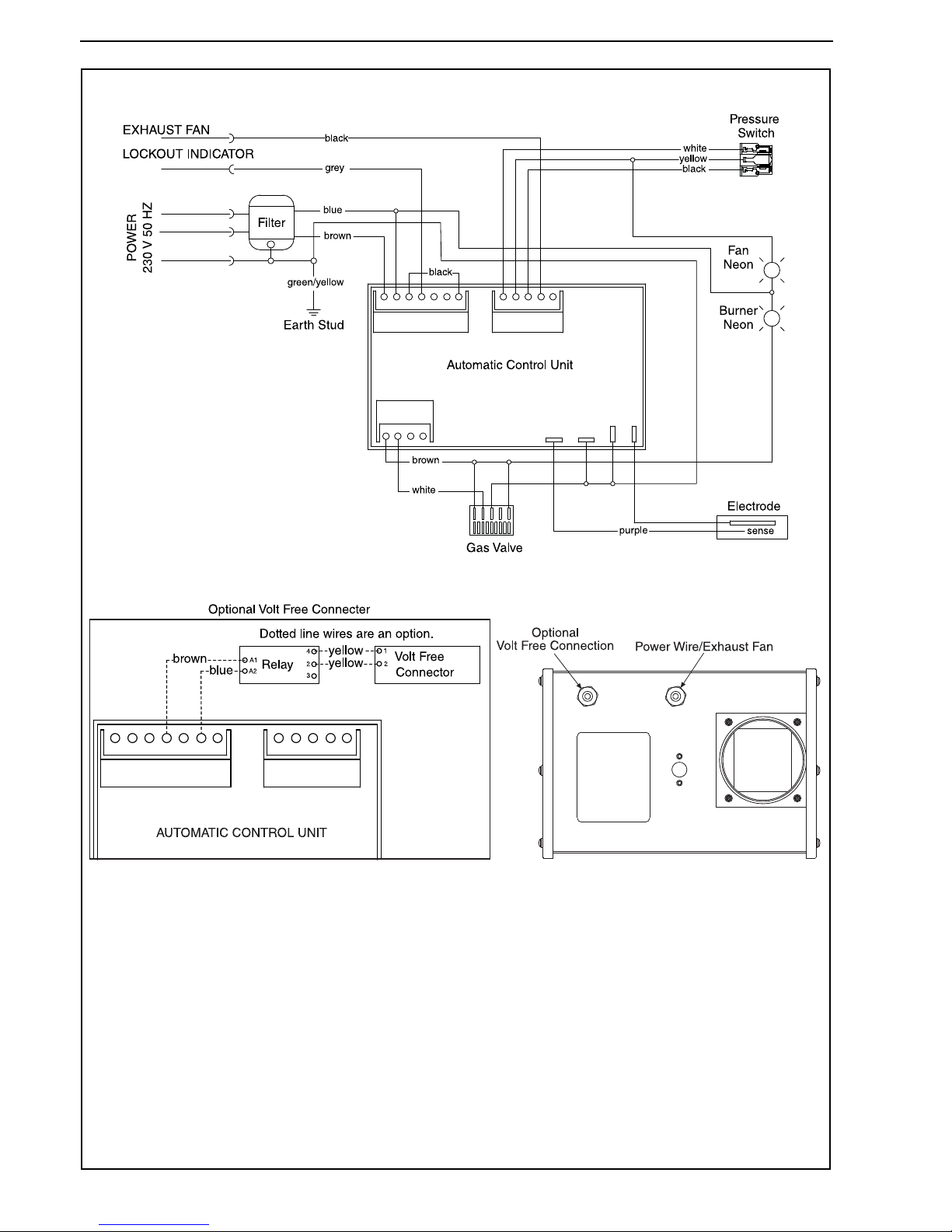
BLACKHEAT® HE INSTALLATION OPERATION AND SERVICE MANUAL
56 of 73
13.5 Internal Wiring Diagram
Note: In the event of a lockout condition, 230 VAC will be present at the lockout indicator. If not used, this wire
must be properly insulated.
If any of the original wire supplied with the heater must be replaced, it must be replaced with wiring material
having a temperature rating of at least 105° C and 600 V.
Page 63
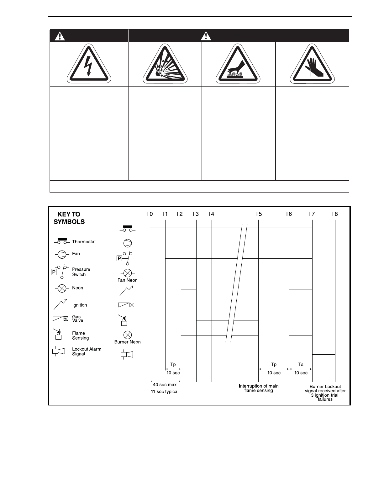
SECTION 14: OPERATION
57 of 73
SECTION 14: OPERATION
Figure 33: Sequence of Operation Chart
NOTE: If the heater operates for more than 24 hours continuously, the ignition module will automatically recycle the
burner to ensure that all safety functions are still in working condition.
14.1 Heater Lockout Indication
In case of flame loss during operation of the heater, the
burner control unit goes to lockout mode after three
ignition trials. At this stage a signal or closed relay will
enable the ROBERTS GORDON
®
controller, BMS
system, etc. to indicate precisely which heater has failed.
This can be done by two options.
14.1.1 Heater Lockout Indicator by Connector
A 230 V signal is provided which enables the ROBERTS
GORDON
®
controller, BMS system, etc. to indicate the
heater that has failed. An additional wire has to be
installed from the heater lockout indicator connector to
the monitoring computer. See Page 56, Section 13.5.
Cut/Pinch Hazard
Wear protective gear
during installation,
operation and service.
Edges are sharp.
WARNING
Failure to follow these instructions can result in death, electric shock, injury or property damage.
Burn Hazard
Allow heater to cool
before service.
Tubing may still be hot
after operation.
Explosion Hazard
Turn off gas supply to
heater before service.
DANGER
Electrical Shock Hazard
Disconnect electric
before service.
More than one
disconnect switch may
be required to
disconnect electric from
heater.
Heater must be
connected to a properly
grounded electrical
source.
Page 64
BLACKHEAT® HE INSTALLATION OPERATION AND SERVICE MANUAL
58 of 73
14.1.2 Heater Lockout Indicator by Volt Free
Connector (Optional)
A volt free contact relay is closed which enables the
ROBERTS GORDON
®
controller, BMS system, etc. to
indicate the heater that has failed. An additional wire has
to be installed from the heater volt free connector to the
monitoring computer. See Page 56, Section 13.5.
14.2 Testing
Establish that a satisfactory purged gas supply and an
electrical supply is available to the heater. Ensure that all
time clocks and thermostats are set to call for heat.
With the gas supply cut off and the electrical supply
isolated by switching off at the local switch, open the
control chamber secured by the screws. Loosen the
sealing screw from the pressure test point and remove
the cover cap from the governor.
Turn on the gas supply and connect appliance electrical
plug. Ensure that the timer or thermostat, if fitted, are set
to call for full gas rate. Switch on at the local switch. The
sequence as described should take place. If not, refer to
detailed fault finding sequence. When flame is
established, check the gas pressure reading and adjust if
necessary. Refer to burner data label.
Check the gas pressure at the outlet of the gas valve. See
Page 73, Section 18.10.1 for pressure settings or refer to
the data plate.
Switch off the electrical supply (shutting down the heater),
remove pressure gauge, tighten pressure test point
screw, ensuring a tight gas seal. Replace governor cover
cap. Replace control chamber door.
14.3 Commissioning (Multiburner)
1. Establish that a satisfactory purged gas supply and
an electrical supply is available to the heater.
2. ENSURE that all the dampers are in the fully open
position.
3. With the gas supply off at each of the burners and
the electrical supply isolated, open the control
chamber secured by six screws.
4. Ensure that all time clocks and thermostats are set
to call for heat.
5. Switch on the electrical supply at the main isolator.
This will start the exhaust fan.
6. Balancing Cold Suction
Check each burner vacuum by connecting an
inclined pressure gauge to the tee on the pressure
switch inlet side in the burner. Adjust the damper so
that the suction is 1.9 mbar. Repeat for each burner.
7. Start at the end burner (furthest from the exhaust
fan) with the inclined pressure gauge connected as
described above. Turn on the gas and electrical supply, reset the pressure switch by removing suction
from the inlet side of the pressure switch waiting
several seconds and reconnecting. The start up
sequence described on Page 57, Section 14 should
take place. If not, refer to detailed fault finding
sequence. When flame is established, check the
gas pressure reading and adjust if necessary. See
data label.
Check the gas pressure at the outlet of the gas
valve. See Page 73, Section 18.10.1 for pressure
settings or refer to the data plate.
Switch off the electrical supply (shutting down the
heater), remove pressure gauge, refit pressure testpoint screw, ensuring a tight gas seal. Replace gov-
ernor cover cap.
Repeat this procedure for each burner in the system.
Close the control chamber and secure with six
screws.
8. Balancing Hot Suction
Reconnect all the burners on the system and allow
them to reach full operating temperature (approximately 20 minutes). Return to each burner and
recheck the hot suctions at the tee on the inlet to the
pressure switch. Re-adjust the damper so that the
hot suction of 1.7 mbar is achieved and lock the
damper in position.
14.4 System Checks
Switch on again at the local switch to help ensure smooth
ignition. Carry out the following system checks:
When running, turn off the gas supply at the appliance.
The heater will immediately shut down followed by one
attempt at restoration followed by lockout.
Linear and Double Linear only:
When running, disconnect the fan plug from the burner.
The unit should shut down within three seconds, proving
operation of the pressure switch.
14.5 User Instructions
After satisfactory testing, ensure that the client is fully
aware of the operation of the system. Bring this manual to
the attention of the user or purchaser; instruct them in the
safe operation of the heater(s).
Description Part Number
Connector male - Volt Free 91324000
Connector female - Volt Free 91324001
Wire Blue 7" 91300004
Wire Brown 7" 91300005
Wire Yellow 12" 91300003
Screw #8 x 3/8 Hex Wshr PHH Type 23 94961406
Base relay P2RF05E C1050B
Relay G2R1-SN IMO 220 V 10 A C1049B
Page 65
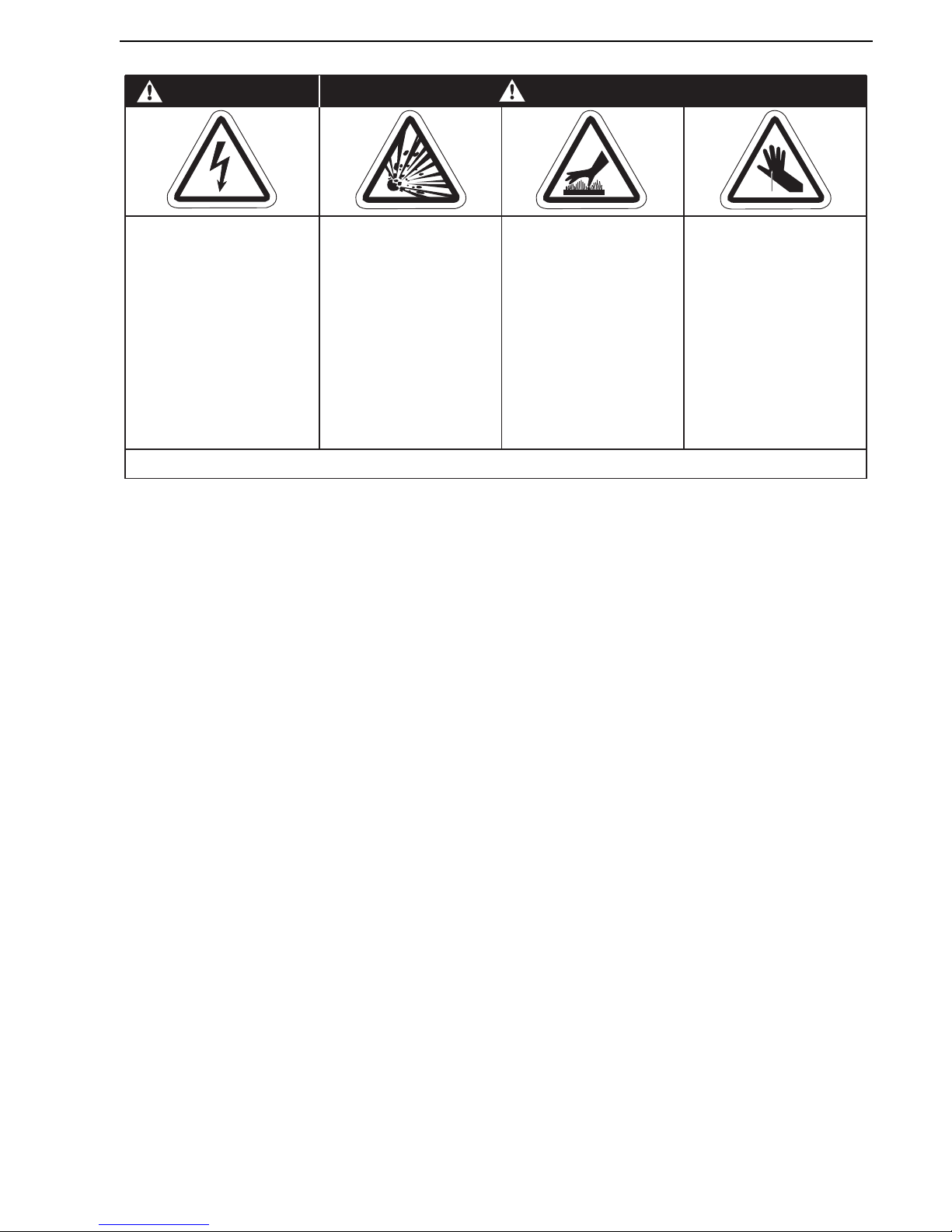
SECTION 15: SERVICING INSTRUCTIONS
59 of 73
SECTION 15: SERVICING INSTRUCTIONS
IMPORTANT: Never use the heater as a support for
ladders or other access equipment. Always test for gas
soundness with a suitable detection fluid after completing
any servicing or exchange of gas carrying component.
On completion of any service/fault finding tasks which
require the breaking and remaking of electrical
connections, the checks:- A: Earth Continuity, B: Polarity
and C: Resistance to Earth must then be repeated.
15.1 Annual Procedure
Carry out the following procedure annually. The preferred
time would be immediately before the winter heating
period. If very dirty conditions arise, it may be necessary
to carry out this procedure more often. If the unit takes in
air through an air duct or filter assembly, more frequent
service may be necessary.
15.1.1 Burner and Fan Removal
Isolate the heater from the gas and electrical supplies.
Remove the fan plug from the burner. Unscrew the
securing screws on the burner flange. The burner can
now be removed. Take care not to disturb the gasket on
the flanged burner tube. Unscrew the securing screw on
the fan flange spigot. The fan can now be removed.
15.1.2 Burner and Fan Removal Maintenance
Remove the fan and burner independently to floor level
and clean both items internally using a soft brush and
compressed air, if available. Take care not to damage the
internal parts of the burner. Check fan impeller for
cleanliness and free rotation.
The electrodes are an integral part of the burner. To
check spark gap, remove the securing screws on the
electrode and withdraw it ensuring the gasket is not
damaged. Spark gap on electrode should be
approximately 3 mm.
15.1.3 Tube and Reflector Maintenance
With burner and fan removed, clean the outer surfaces of
the tubes using a brush and wipe the inner surface of the
reflector with a soft damp cloth - use a household
detergent if necessary. Never use abrasive cleaners on
the reflectors. Reassemble the burner and fan in reverse
order. Carry out the Testing Procedure. See Page 58,
Section 14.2.
15.2 Sealing Gaskets
During annual service, all gaskets, as indicated on Page
68, Section 17, must be inspected for cuts, misalignment
or dryness. All round rubber gaskets, sealing the screw
holes, must be replaced in three year intervals or earlier
as needed. All other gaskets must be replaced every five
years or earlier as needed.
Old gaskets must be removed completely before installing
the new gasket. When replacing gaskets on screws,
ensure that the screws are not over tightened.
Deformation of the gasket is an indication of suffcient
torque. The control and combustion chamber doors have
internal seals, replacements must be attached to the
same location.
15.3 Component Removal
First, isolate the heater from the gas and electricity
supply.
Entry to the burner assembly is gained by removing the
six door screws and removing the control chamber door.
Entry to the combustion chamber is gained by removing
the combustion chamber door.
Cut/Pinch Hazard
Wear protective gear
during installation,
operation and service.
Edges are sharp.
WARNING
Failure to follow these instructions can result in death, electric shock, injury or property damage.
Burn Hazard
Allow heater to cool
before service.
Tubing may still be hot
after operation.
Explosion Hazard
Turn off gas supply to
heater before service.
DANGER
Electrical Shock Hazard
Disconnect electric
before service.
More than one
disconnect switch may
be required to
disconnect electric from
heater.
Heater must be
connected to a properly
grounded electrical
source.
Page 66
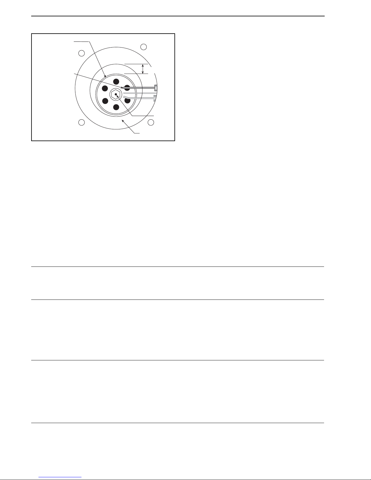
BLACKHEAT® HE INSTALLATION OPERATION AND SERVICE MANUAL
60 of 73
15.3.1 Electrode
Figure 34: Burner Cup Position
15.3.2 Burner Head/Injector Jet
When the cover is removed completely, the burner
assembly is exposed. Unscrew the burner cup. Remove
brass injector jet (orifice). Replace in reverse sequence.
15.3.3 Solenoid Valve/Governor
Remove burner head. Unscrew two screws securing the
solenoid/governor body. Withdraw the electrical
connector and remove the flexible gas line connector. The
solenoid/governor and fittings can now be withdrawn from
the compartment. To ensure IP55 protection, replace the
gasket on the gas valve inlet flange (P/N 03200100).
The solenoid(s) can be removed from the body by
unscrewing central screw. Replace in reverse sequence.
15.3.4 Automatic Flame Control Unit
Remove black ignition lead. Withdraw the 10 point edge
connector. Unscrew two screws from the cover. Replace if
faulty. Refit in reverse sequence.
15.3.5 Pressure Switch
Disconnect the two silicone tubes. Remove electrical
plug. Remove one screw which secures the pressure
switch to the burner. Remove pressure switch.
Replace pressure switch, if faulty, and refit in reverse
sequence ensuring that the rubber tubes are reconnected
to the switch correctly.
15.3.6 Neons
Remove the two push on connectors and unscrew the
nut. Replace in reverse sequence.
15.4 Maintenance Checklist
Installation Code and Annual Inspections:
All installation and service of ROBERTS GORDON
®
equipment must be performed by a contractor qualified in
the installation and service of equipment sold and
supplied by Roberts-Gordon Europe Limited and conform
to all requirements set forth in the ROBERTS GORDON
®
manuals and all applicable governmental authorities
pertaining to the installation, service, operation and
labeling of the equipment.
To help facilitate optimum performance and safety,
Roberts-Gordon Europe Limited recommends that a
qualified contractor conduct, at a minimum, annual
inspections of your ROBERTS GORDON
®
equipment
and perform service where necessary, using only
replacement parts sold and supplied by Roberts-Gordon
Europe Limited.
Burner Cup
(center horizontally)
Electrode
Assembly
16 mm
Air Plate
Jet
The Vicinity of the Heater
Do not store or use flammable objects, liquids or vapours near the heater.
Immediately remove these items if they are present.
See Page 5, Section 3.
Vehicles and Other
Objects
Maintain the clearances to combustibles.
Do not hang anything from, or place anything on, the heater.
Make sure nothing is lodged underneath the reflector, in between the tubes or in the
decorative or protective grilles (included with select models).
Immediately remove objects in violation of the clearances to combustibles.
See Page 5, Section 3.
Reflector
Support reflector with reflector hanger and support strap.
Reflector must not touch tube.
Make sure there is no dirt, sagging, cracking or distortion.
Do not operate if there is sagging, cracking or distortion.
Make sure reflectors are correctly overlapped.
Clean outside surface with a damp cloth.
Page 67
SECTION 15: SERVICING INSTRUCTIONS
61 of 73
Vent Pipe
Venting must be intact. Using a flashlight, look for obstructions, cracks on the pipe,
gaps in the sealed areas or corrosion.
The area must be free of dirt and dust.
Remove any carbon deposits or scale using a wire brush.
See Page 49, Section 11.
Outside Air Inlet
Inlet must be intact. Look for obstructions, cracks on the pipe, gaps in the sealed
areas or corrosion.
The area must be free of dirt and dust. Clean and reinstall as required.
Tube s
Make sure there are no cracks.
Make sure tubes are connected and suspended securely.
See Page 11, Section 5.
Make sure there is no sagging, bending or distortion.
Gas Line
Check for gas leaks. See Page 52, Section 12.
Burner Observation
Window
Make sure it is clean and free of cracks or holes.
Clean and replace as required.
Blower Scroll, Wheel and
Motor
Compressed air or a vacuum cleaner may be used to clean dust and dirt.
Burner Cup and Orifice
Clear of obstructions (even spider webs will cause problems).
Carefully remove any dust and debris from the burner.
Electrode
Replace if there are cracked ceramics, excessive carbon residue, or erosion of the
electrode.
The electrode gap should be 3 mm.
Thermostat
There should be no exposed wire or damage to the thermostat.
See Page 54, Section 13.
Suspension Points
Make sure the heater is hanging securely.
Look for signs of wear on the chain or ceiling.
See Page 11, Section 5.
Sports Hall Guard,
Decorative and Protective
Grilles (optional)
The grille must be securely attached. If the grille is loose or off, contact a contractor
qualified in the installation and service of gas-fired heating equipment for repair.
Check that side reflector extensions are installed correctly and secured in place if
necessary. (Decorative grille only.)
See Page 44, Section 10.3.3 and Page 45, Section 10.4.
Make sure shield is installed correctly and secured in place if necessary.
(Decorative grille only.) See Page 44, Section 10.3.2.
Wall Tag
If a wall tag is present, make sure it is legible and accurate. Please contact
Roberts-Gordon Europe Limited or your ROBERTS GORDON
®
independent
distributor if you need a wall tag. See Page 4, Section 2.1.
Safety Labels
Product safety signs or labels should be replaced by the product user when they are
no longer legible. Please contact Roberts-Gordon Europe Limited or your
ROBERTS GORDON
®
independent distributor to obtain replacement signs or
labels. See Page 3, Figure 1 through Page 3, Figure 2.
Page 68
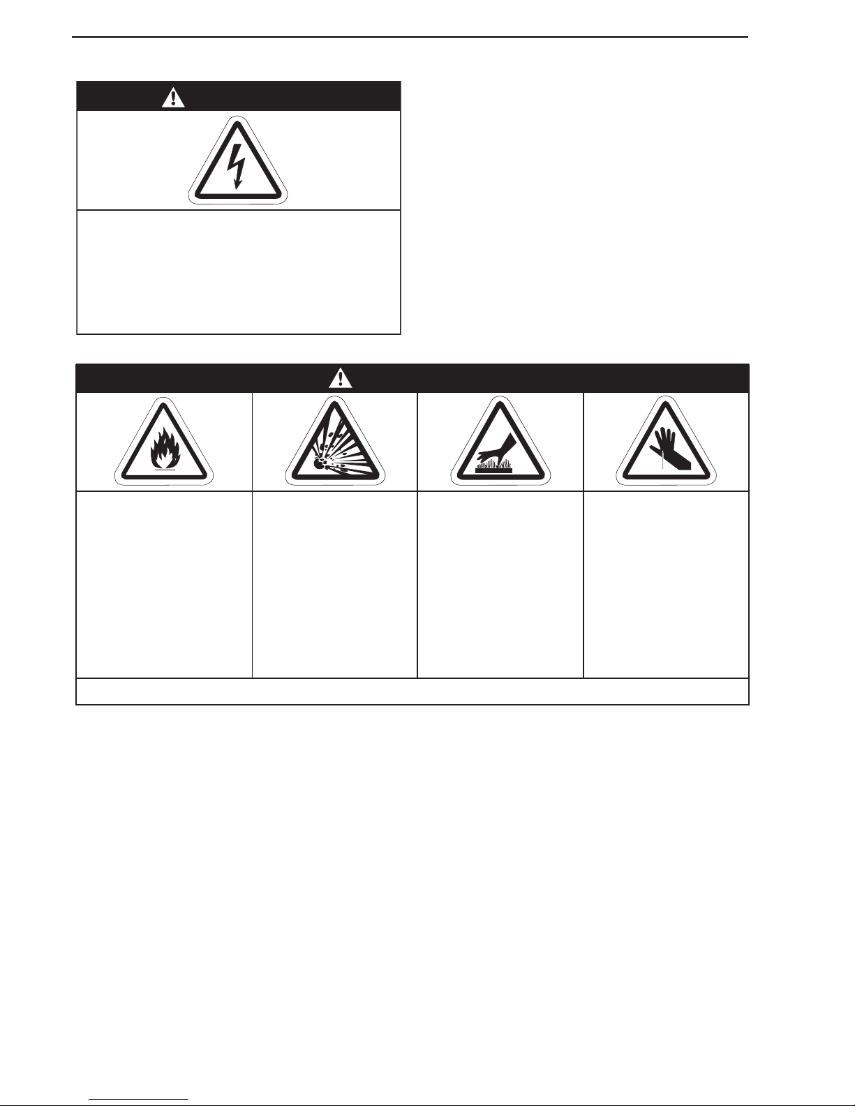
BLACKHEAT® HE INSTALLATION OPERATION AND SERVICE MANUAL
62 of 73
SECTION 16: TROUBLESHOOTING
DANGER
Electrical Shock Hazard
Disconnect electric before service.
Heater must be properly grounded.
Failure to follow these instructions can result
in death or electrical shock.
Fire Hazard
Keep all flammable
objects, liquids and
vapors the minimum
required clearances to
combustibles away
from heater.
Some objects will catch
fire or explode when
placed close to heater.
Cut/Pinch Hazard
Wear protective gear
during installation,
operation and service.
Edges are sharp.
WARNING
Failure to follow these instructions can result in death, injury or property damage.
Burn Hazard
Allow heater to cool
before service.
Tubing may still be hot
after operation.
Explosion Hazard
Turn off gas supply to
heater before service.
Page 69
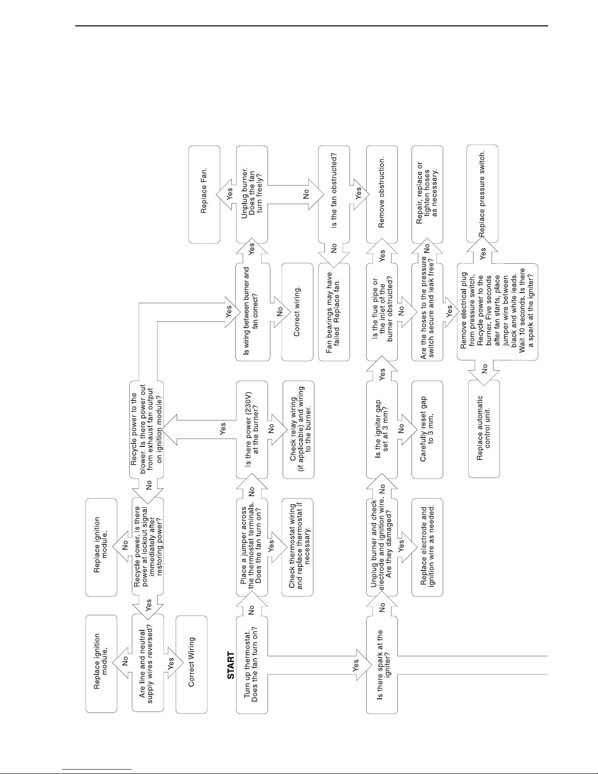
SECTION 16: TROUBLESHOOTING
63 of 73
16.1 Troubleshooting Flow Chart (Linear, Double Linear and U-Tube)
Page 70
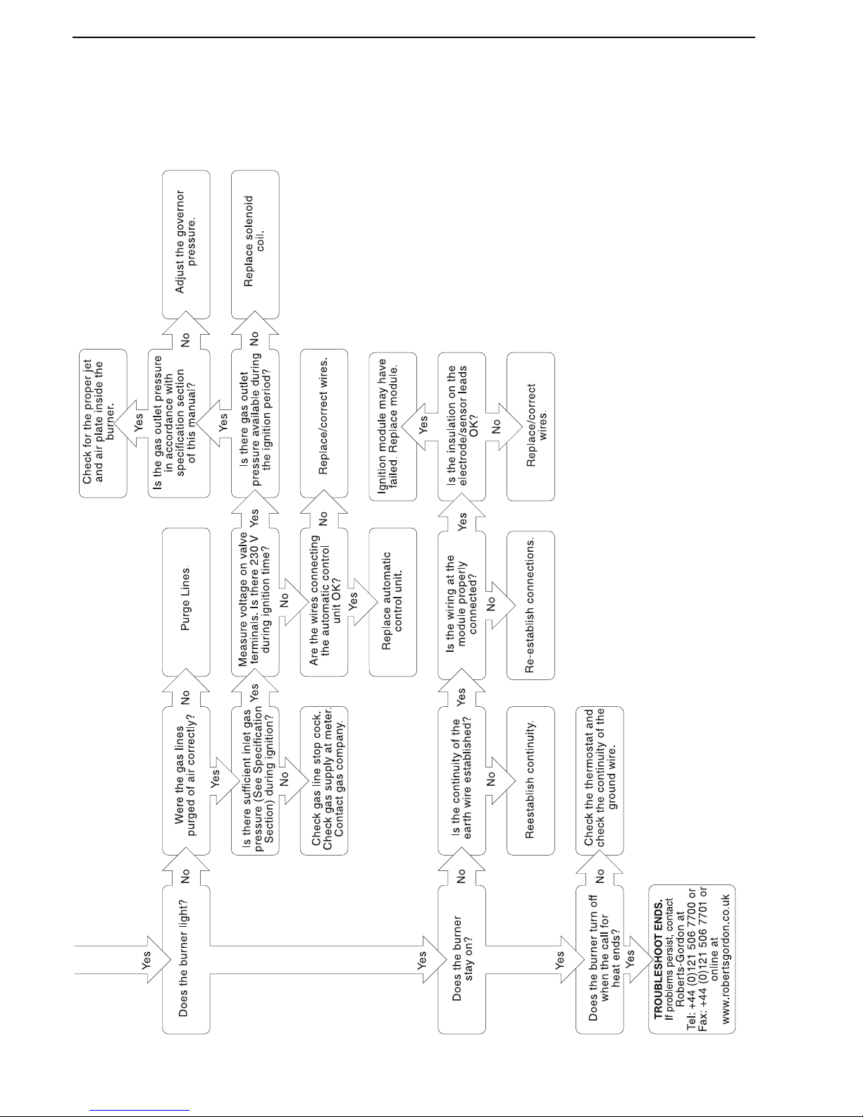
BLACKHEAT® HE INSTALLATION OPERATION AND SERVICE MANUAL
64 of 73
Troubleshooting Flow Chart (Linear, Double Linear and U-Tube)
Page 71
SECTION 16: TROUBLESHOOTING
65 of 73
16.2 Troubleshooting Flow Chart (Multiburner)
Refer to control panel
IOS manual for
troubleshooting.
Fan motor may have to
be replaced.
Remove obstruction.
No
Ye s
Is there an obstruction to
the pump impeller?
No
No Ye sYe sNo
No
Ye s
NoNoYe s
Ye s
Ye s
Ye s
No
No
Ye s
No
Ye s
Ye s
No
No
Check thermostat
and replace if
necessary.
Turn up thermostat.
Does the fan turn on?
Remove obstruction.
Repair, replace or
tighten hoses
as necessary.
Is the flue pipe or
the inlet of the
burner obstructed?
Are the hoses to the
pressure switch secure
and leak free?
Replace pressure switch.
Is the igniter gap
set at 3 mm?
Carefully reset gap
to 3 mm.
Replace automatic
control unit.
Unplug burner and check
electrode and ignition wire.
Are they damaged?
Replace electrode and
ignition wire as needed.
After 20 second pre-purge
Is there spark at the igniter?
Check clock program.
Reset as required.
Is there power (230
V)
to the control panel?
Is the clock set to on?
Is there power output
to the fan?
Disconnect power to the
motor. Does the
motor turn freely?
Motor may have have
tripped overload switch.
Wait 10 - 15 minutes for
automatic reset.
Is the motor connected
properly? Refer to the
wiring diagrams on the
motor and in the
installation manual.
Remove electrical plug
from the pressure switch;
place jumper between
black & white leads.
Does the fan turn on?
Page 72
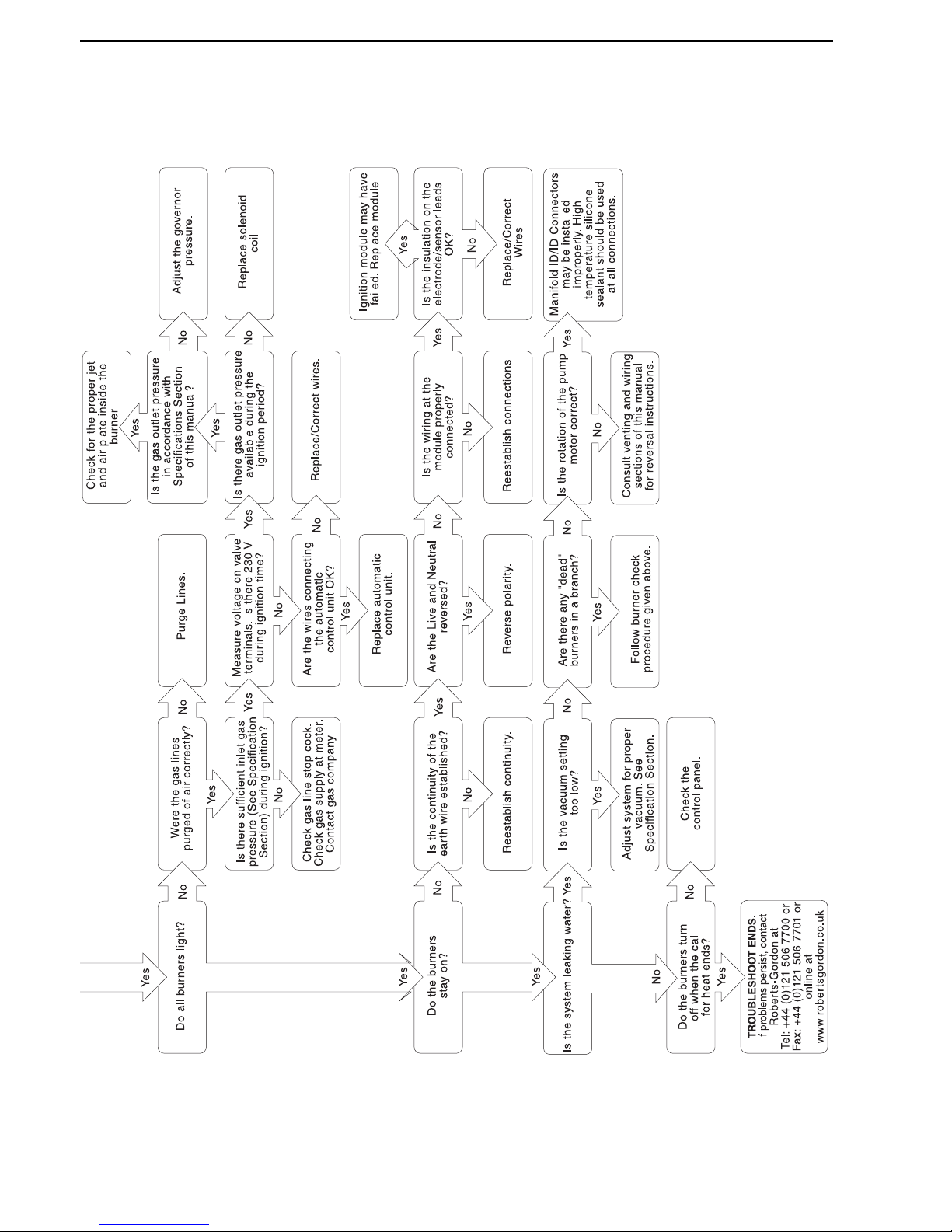
BLACKHEAT® HE INSTALLATION OPERATION AND SERVICE MANUAL
66 of 73
Troubleshooting Flow Chart (Multiburner)
Page 73
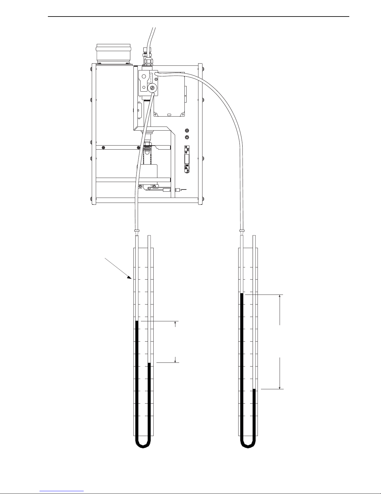
SECTION 16: TROUBLESHOOTING
67 of 73
16.3 Manifold Gas Pressure Setting
0
1
2
3
4
5
6
1
2
3
4
5
6
0
1
2
3
4
5
6
1
2
3
4
5
6
Manometer
4
RELAY
3
(14)
(12)
2
(A1)
1(-)
(A2)
5(+)
Combustion Chamber
Control Chamber
Governor (orifice) pressure
while burner is running. See
Page 73, Section 18.10.1.
Gas supply pressure
while burner is running. See
Page 71, Section 18.2.3.
Page 74
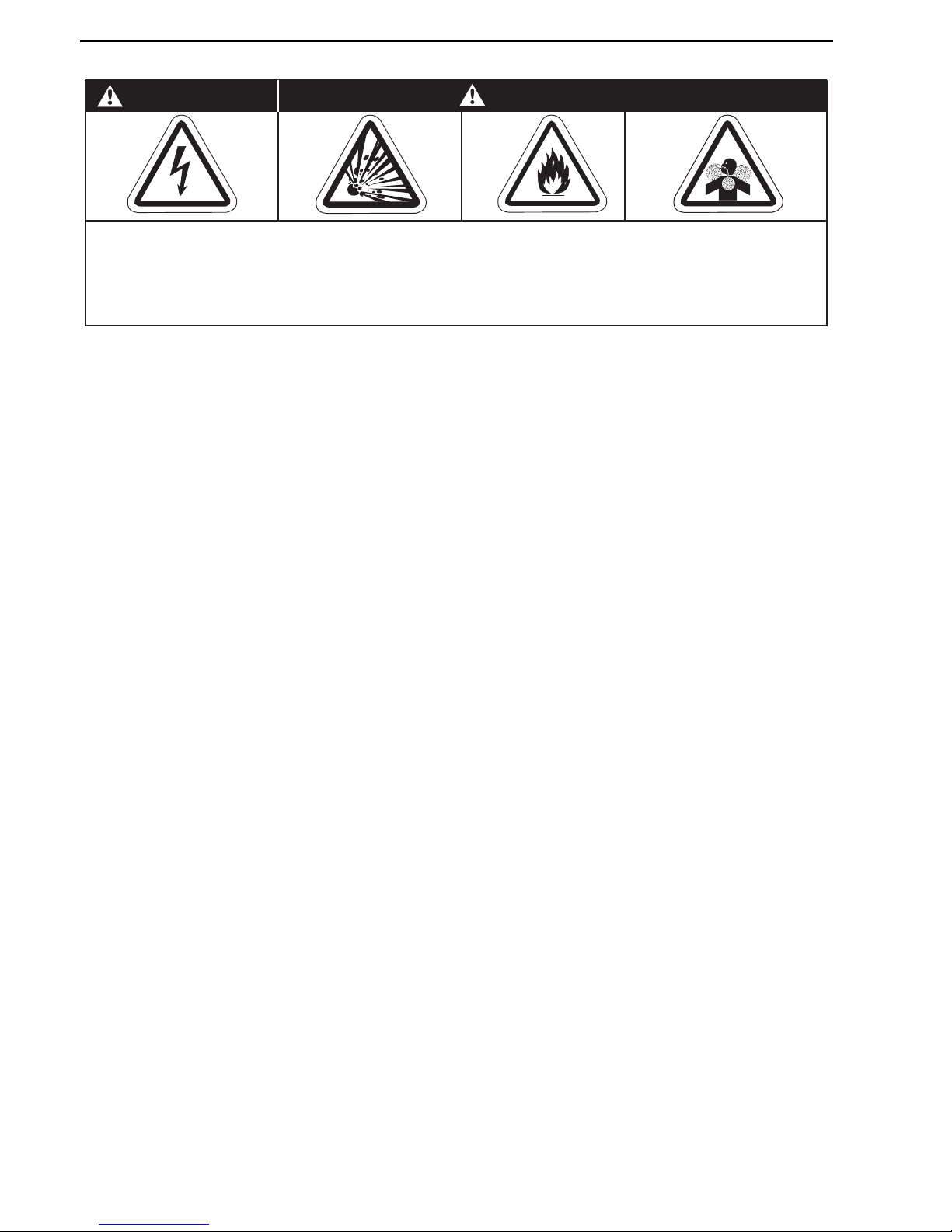
BLACKHEAT® HE INSTALLATION OPERATION AND SERVICE MANUAL
68 of 73
SECTION 17: REPLACEMENT PARTS
See warnings and important information before removing or replacing parts. After any maintenance or repair work,
always test fire the heater in accordance with the start-up instructions on Page 57, Section 14 to help ensure all safety
systems are in working order before leaving the heater to operate. Minor faults may be traced by using the
troubleshooting charts on Page 62, Section 16 through Page 67, Section 16.3.
Carbon Monoxide Hazard
WARNING
Use only genuine ROBERTS GORDON
®
replacement parts per this installation, operation and
service manual.
Failure to follow these instructions can result in death, electric shock, injury or property damage.
Explosion Hazard
DANGER
Electrical Shock Hazard
Fire Hazard
Page 75
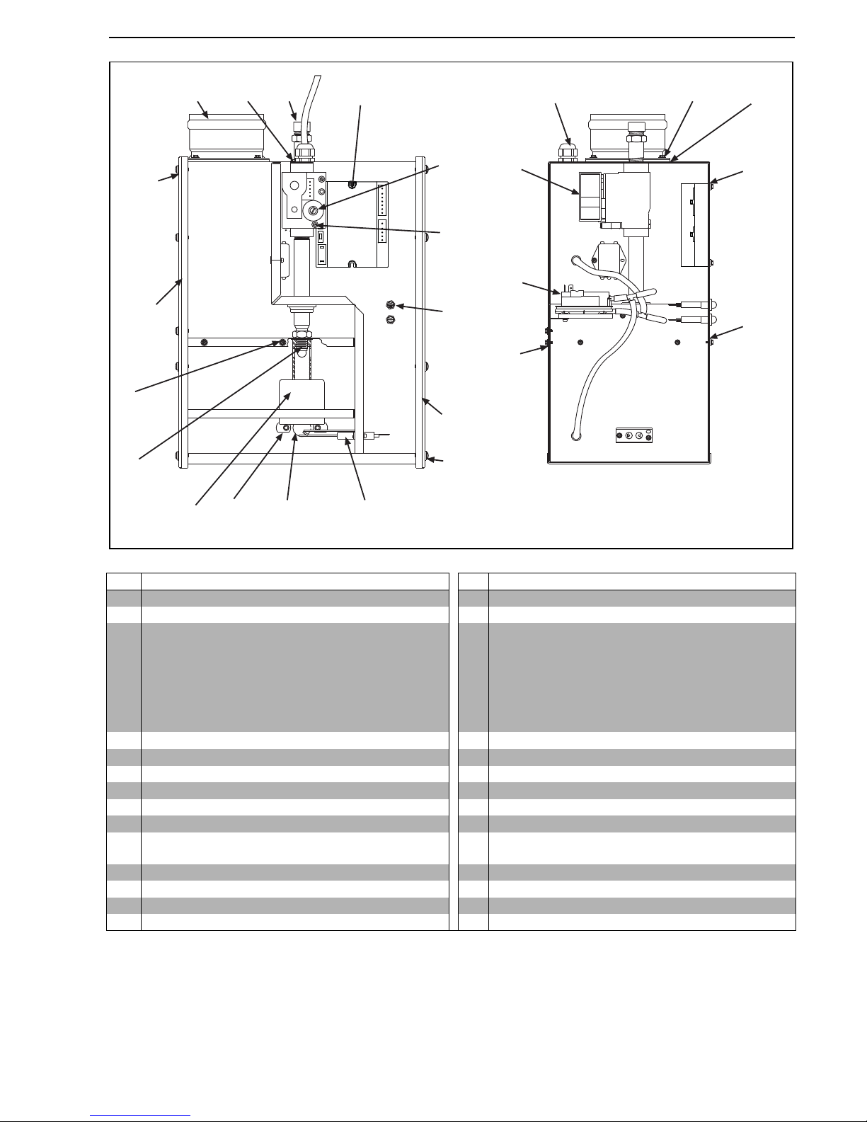
SECTION 17: REPLACEMENT PARTS
69 of 73
*See Page 70, Section 17.1.
Item Description Part Number Item Description Part Number
A Automatic Control Unit 90438704 P Gasket 1/2" OD x 1/4" ID 92700008
B Flex Line Adapter 91220700 Q Gasket 1/2" OD x 3/16" ID 92700001
C
Pressure Switch for
HE50
HE35
HE15, 20, 30, 45
HE25
HE40
90439801
90439802
90439803
90439804
90439805
R Gasket 3/8" OD x 3/16" ID 92700002
D Amber Neon Lamp 91320604 S Valve Gasket 03200100
E* Gas Valve 90033101 T Window Gasket 92700003
FGovernor Screw N/A U Fresh Air Adaptor Gasket 92700005
G Outlet Pressure Tap N/A V Gasket 1/2" x 17 3/8" 92700006
H Cable Gland U169 W Gasket 1/2" x 8.5" 92700007
I Star Washer 96212100 N/S Ignition Wire 90427704
J
Jet Orifice
(See Page 73, Section 18.10)
N/A N/S Burner Tube Gasket 92700004
K Burner Cup Assembly 03020100 N/S Wire Harness- Main Power 03320404
L Mica Window Assembly 03360004 N/S Wire Harness- Pressure Switch 03320405
M Electrode Assembly 90427403 N/S Purple Wire 07250007
N Fresh Air Adapter 90501002 N/S Electrode Gasket 02558501
A
B
C
D
E
F
G
H
J
I
K
L, T
(2)
M
N
P
R
SV
V
(2)
W
(2)
Q
(6)
V
(2)
W
(3)
Q
(7)
R
(4)
R
(2)
R
(3)
Page 76
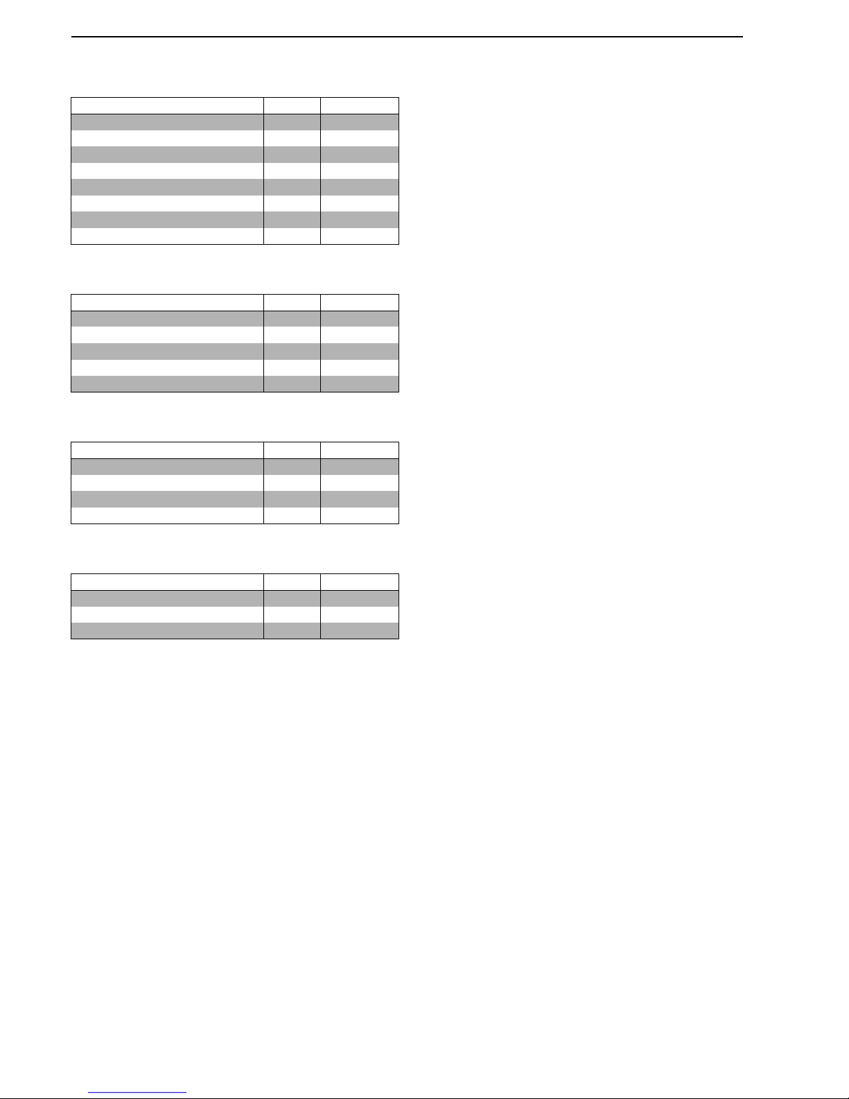
BLACKHEAT® HE INSTALLATION OPERATION AND SERVICE MANUAL
70 of 73
17.1 Replacement Packages
17.1.1 Screw and Gasket Replacement Package
(P/N 03360005)
17.1.2 Viewer Window Replacement Package
(P/N 03360004)
17.1.3 Door Gasket
Replacement Package (P/N 03360002)
17.1.4 Gas Valve
Replacement Package (P/N 03360003)
Description Quantity Part Number
Screw M4 x 8mm 2 93304506
Screw 10-24 x 5/8 4 94118110
Screw #8 x 3/8 4 94118107
Screw M8 x 20 mm 2 93304507
Burner Tube Gasket 1 92700004
Fresh Air Intake Gasket 1 92700005
Rubber Gasket 10 92700002
Gas Valve Gasket 1 03200100
Description Quantity Part Number
Viewer Ring 1 01390203
Mica Window Square 1 02553200
Window Gasket 2 92700003
Screw M6 x 16 mm 2 93304505
Rubber Gasket 2 92700008
Description Quantity Part Number
Screw 10-24 x 5/8 2 94118110
Silicone Gasket 4 92700006
Silicone Gasket 6 92700007
Rubber Gasket 13 92700001
Description Quantity Part Number
Gas Valve SIT 840 1 90033101
Screw M4 x 8 mm 2 93304506
Gas Valve Gasket 1 03200100
Page 77

SECTION 18: SPECIFICATIONS
71 of 73
SECTION 18: SPECIFICATIONS
18.1 Material Specifications
18.1.1 Combustion and Tubes
100 mm dia. 16 gauge heat treated aluminised
mild steel.
18.1.2 Reflectors
NS3 H14 aluminium or 1.4016 2R stainless
steel (option).
18.2 Heater Specifications
18.2.1 Sequence Controller
Fully automatic, single try, direct spark,
100% shut off ignition flame rectification module.
18.2.2 Electrical
Rating: 230 V, 50 Hz, 1 Ø, 1 A
Connection: minimum IP55 junction box
18.2.3 Gas Supply
Connection: Rc1/2 (1/2" BSP int)
Natural G20:
Minimum - Inlet 15 mbar (6 in wg)
Maximum - Inlet 50 mbar (20 in wg)
Natural G25:
Minimum - Inlet 17.5 mbar (7 in wg)
Maximum - Inlet 50 mbar (20 in wg)
LP Gas (Propane or Butane):
Minimum - Inlet 32.5 mbar (13 in wg)
Maximum - Inlet 50 mbar (20 in wg)
18.3 Venting Specifications
18.3.1 IP55 Protected Fans
HE15, 20, 25, 30, 35, 40,
HE45, 50, HE30DL,
HE40DL, 50DL, 70DL ...... Model: Torin DSA 146-052
(P/N 90710053)
Multiburner ...................... Model: Airflow 83 BWLG IP55
...................... Model: Airflow 90 BWLT IP55
Consult the manufacturer for availability of alternate fans.
18.3.2 Flue
The flue must be 100 mm, or greater in diameter, and
must conform to National Codes. The flue must be self
supporting. Inlet must be 100 mm diameter.
Multiburner - Flue will be 150 mm diameter. Flue material
must conform to National Codes. The flue must be self
supporting.
18.4 Suspension Specifications
Hang heater with materials with a minimum working load
of 33 kg.
18.5 Controls Specifications
Time switches, thermostats, etc. can be wired into the
electrical supply. External controls supplied as an
optional extra.
18.6 Environment
The heater is limited to operate in an ambient
temperature range of 0° C - 32° C (32° F - 86° F) with a
maximum relative humidity of 95%.
Page 78
BLACKHEAT® HE INSTALLATION OPERATION AND SERVICE MANUAL
72 of 73
18.7 Linear Heater
HE15ST
HE20ST
HE25ST
HE30ST
HE35ST
HE40ST
HE45ST
HE50ST
Input - Gross (kW) 15 20 25 30 35 40 45 50/51
Input - Net (kW) 13.5 18 22.5 27 31.5 36 40.5 45/46
Tube Length (mm) 6096 9144 9144 12192 12192 12192 15240 15240
Overall Heater Length (mm) 6887 9935 9935 12983 12983 13028 16076 16076
Weight (kg) 51 66 66 84 84 84 99 103
Heated Area (m
2
) 20-160 30-210 40-265 50-315 55-370 65-420 70-475 80-525
Minimum Installation Height (mm) 3500 3500 3500 3500 4600 5000 5000 5000
Recommended Installation Height
(mm)
3500 3600 3900 4200 4800 5500 6700 7600
18.8 Double Linear Heater
HE30DL
HE40DL
HE50DL
HE60DL
HE70DL
Input - Gross (kW) 30 40 50 60 70
Input - Net (kW) 27.536455463
Tube Length (mm) 12802 18898 18898 24994 24994
Overall Heater Length (mm) 13914 20010 20010 26106 26106
Weight (kg) 92 124 129 164 164
Heated Area (m
2
) 50-315 65-420 80-525 100-630 110-740
Minimum Installation Height (mm) 3500 3500 3500 3500 4600
Recommended Installation Height (mm) 3500 3600 3900 4200 4800
18.9 U-tube Heater
HE15UT
HE20UT
HE25UT
HE30UT
HE35UT
HE40UT
HE45UT
HE50UT
Input - Gross (kW) 15 20 25 30 35 40 45 50
Input - Net (kW) 13.5 18 22.5 27 31.5 36 40.5 45
Tube Length (mm) 3531 5055 5055 6579 6579 6579 8103 8103
Overall Heater Length (mm) 4048 5572 5572 7096 7096 7096 8620 8620
Weight (kg) 59 73 73 90 90 90 108 113
Heated Area (m
2
) 20-160 30-210 40-265 50-315 55-370 65-420 70-475 80-525
Minimum Installation Height (mm) 3500 3500 4000 4700 5000 5000 5000 5000
Recommended Installation Height (mm) 3500 3600 4000 4700 5000 5500 6700 7600
Page 79
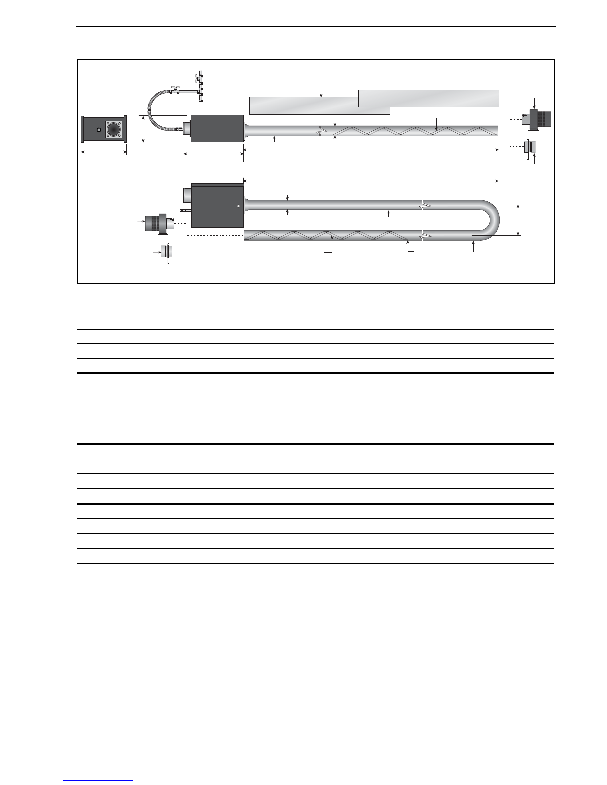
SECTION 18: SPECIFICATIONS
73 of 73
18.10 Burner Specifications
Figure 35: Linear and U-tube Specifications
18.10.1 Standard Burner Specifications
**Based on Gross Caloric Value.
Fan
Damper
Swirler*
Side View
Reflector
End View
Internal Swirler*
Tube Length
Tube Length
Fan Tube
U-Tube
Plan View
Fan
Burner Tube
Burner Tube
100 mm
100 mm
Damper
*Swirler must always be located in Fan Tube.
457 mm
348 mm
499 mm
241 mm
Models HE15 HE20 HE25 HE30 HE35 HE40 HE45 HE50
Burner Airplate ID Number 515 505 513 502 500 501 500 506
Jet Numbers - Natural G20 & 25 #31 #28 5/32 #17 #12 #8 #3 #1
Jet Numbers - Propane/Butane #47 #43 #39 #33 #31 3.2 mm #29 #28
Gas Consumption**Natural G20 (m
3
/h) 1.43 1.91 2.38 2.86 3.34 3.81 4.29 4.76
Natural G25 (m
3
/h) 1.66 2.22 2.77 3.32 3.88 4.43 4.99 5.54
Propane (m
3
/h)
[kgh]
0.56
[1.08]
0.75
[1.44]
0.94
[1.80]
1.13
[2.16]
1.32
[2.52]
1.51
[2.88]
1.69
[3.25]
1.88
[3.61]
Butane (m
3
/h) 0.43 0.57 0.72 0.86 1.00 1.15 1.29 1.43
Governor Pressure Butane (mbar) 20.4 20.4 19.7 19.7 19.7 19.7 20 20.9
Butane (in wg) 8.1 8.2 7.9 7.9 7.9 7.9 8.0 8.4
Propane (mbar) 28.4 27.1 26.9 26.6 26.9 26.9 27.4 26.9
Propane (in wg) 11.4 10.9 10.8 10.7 10.8 10.8 11.0 10.8
Governor Pressure Natural G20 (mbar) 10.0 9.5 9.5 9.5 9.2 9.5 8.7 8.7
Natural G20 (in wg) 4.0 3.8 3.8 3.8 3.7 3.8 3.5 3.5
Natural G25 (mbar) 15.4 14.9 15.2 14.9 14.2 14.9 13.7 13.2
Natural G25 (in wg) 6.2 6.0 6.1 6.0 5.7 6.0 5.5 5.3
Page 80

Page 81

Page 82
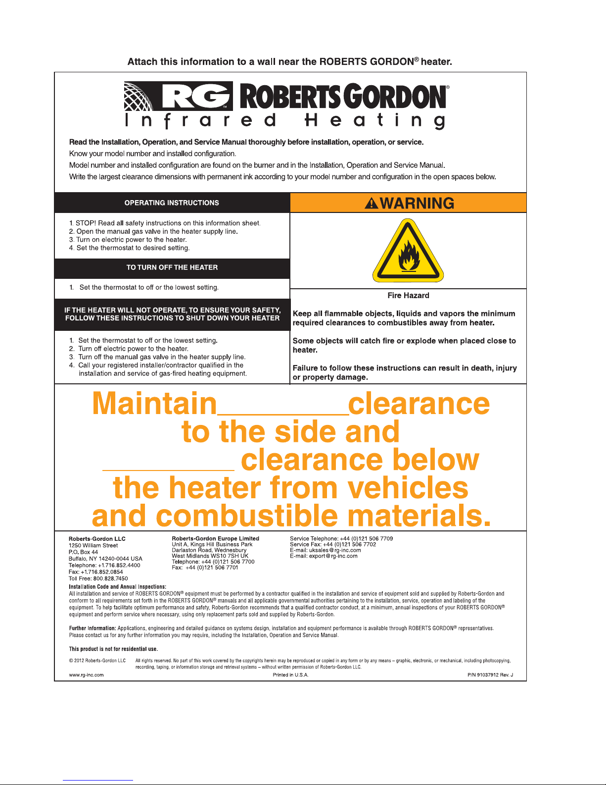
 Loading...