

Page 1
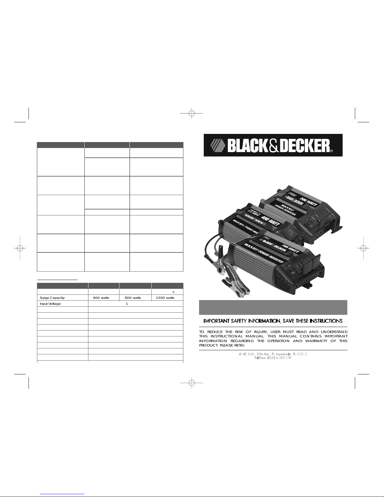
VEHICLE POWER SYSTEM
POWER INVERTER
200/400/750 WATT
VEC1045BD / VEC1046BD / VEC1047BD
USER’S MANUAL
& WARRANTY INFORMATION
IIIIMMMMPPPPOOOORRRRTTTTAAAANNNNTTTTSSSSAAAAFFFFEEEETTTTYYYYIIIINNNNFFFFOOOORRRRMMMMAAAATTTTIIIIOOOONNNN,,,,SSSSAAAAVVVVEEEETTTTHHHHEEEESSSSEEEEIIIINNNNSSSSTTTTRRRRUUUUCCCCTTTTIIIIOOOONNNNSS
SS
TO REDUCE THE RISK OF INJURY, USER MUST READ AND UNDERSTAND
THIS INSTRUCTIONAL MANUAL. THIS MANUAL CONTAINS IMPORTANT
INFORMATION REGARDING THE OPERATION AND WARRANTY OF THIS
PRODUCT. PLEASE RETAIN FOR FUTURE REFERENCE.
www.vectormfg.com
4140 S.W. 30th Ave., Ft. Lauderdale, FL 33312
Toll Free: (800) 618-5178
8
Fault Protection Code and Troubleshooting Guide
INVERTER POWER SWITCH TURNED ON
SPECIFICATIONS
Power Inverter Model VEC1045BD VEC1046BD VEC1047BD
Maximum Continuous Power: 200 watts 400 watts 750 watts
Surge Capacity: 400 watts 800 watts 1500 watts
Input Voltage: 12.8 volts
Output Voltage: Approx. 115 volt AC RMS 60 Hz
Low Voltage Alarm: 11 volts DC ± 0.3 volt DC
Low Voltage Shutdown: 10.5 volts DC ± 0.3 volt DC
Thermal Shutdown: Automatic
Wave Form: Modified Sine Wave (MSW)
Output Connection: North American Standard Receptacles
Input Fuses: Internal
Input Cables: Battery cable with ring connector
Additional Protection: Overload, over voltage, overheating
Trouble/Indication Possible Cause Suggested Remedy
No AC output — DC input is out of range Check battery voltage.
(red LED lit
Excessive load — Turn unit off. Reduce the load,
thermal shutdown wait for the inverter to cool
down, then turn the unit on
again.
No AC output — Fuse(s) open Check DC input — fuse(s) in
green LED not lit vehicle. Replace the fuse with
one of the same type and rating
if necessary.
Low battery alarm Low battery voltage Recharge battery. Remove
sounds continuously load from the inverter while
recharging battery.
Bad connection or wiring Tighten all DC connections.
Motorized power tool Excessive start-up load If appliance does not star t,
will not start appliance is drawing
excessive voltage and
will not work with inverter.
Motorized power tool Purely inductive load Make the load not purely
does not operate at inductive. Operate an
correct speed incandescent lamp at the
same time as motor.
Television/Radio Snow in picture, Keep inverter and antenna
interference “buzzing” sound distant from each other. Use
shielded antenna. Connect
antenna to amplifier.
VEC1045_46_47_BD_Manual 4/28/05 5:16 PM Page 8
Page 2

iii
Important Cable Information
Substantial power loss and reduced battery operating time results from inverters installed with cables that
are not able to supply full power. Symptoms of low battery power can result from cables that are either
excessively long or an insufficient gauge. Marine installations are also subjected to vibration and stresses
that exceed those of other mobile installations. Therefore, the installer/operator should be especially
aware of the requirements to maintain secure, tight, water-resistant electrical connections and to provide
for strain relief for DC cables and appliance wiring. Cable insulation must be the appropriate type for
the environment.
SAVE THESE INSTRUCTIONS
IMPORTANT SAFETY INSTRUCTIONS
To ensure reliable service, your power inverter must be installed and used properly. Please read the
installation and operating instructions thoroughly prior to installation and use. Pay particular attention to
the WARNING and CAUTION statements in this manual. The CAUTION statements advise against
certain conditions and practices that may result in damage to your inverter. The WARNING statements
identify conditions or practices that may result in personal injury.
Read All Instructions Before Using This Power Inverter!
WARNINGS
TO REDUCE THE RISK OF FIRE, ELECTRIC SHOCK, EXPLOSION OR INJURY:
• Do not connect to AC distribution wiring.
• Remove appliance plug from outlet strip or turn off inverter before working on the
appliance. Multiple outlet power strips with switches and circuit breakers only
interrupt power to the "hot" receptacle terminals. The "neutral" terminals remain
powered with respect to the "ground" terminals.
• NOT approved for ignition protected areas. Do not make any electrical connections
or disconnections in areas designated as IGNITION PROTECTED.
• This is not a toy — keep away from children.
• This equipment employs components that tend to produce arcs or sparks. DO NOT
install in compartments containing batteries or flammable materials.
• Use this unit in properly ventilated areas ONLY.
• Do not open — there are no user-ser viceable parts inside.
• Do not inser t foreign objects into the outlet.
• Do not expose the unit to water, rain or snow.
CAUTIONS
• Always inspect batter y supply connections and cables to ensure they are tight and
that cable insulation is not damaged.
• Do not use with positive ground electrical systems (the majority of modern
automobiles, RVs, trucks and boats are negative ground). Reverse polarity
connection will result in a blown fuse and may cause permanent damage to the
inverter and will void warranty.
• This inver ter will not operate high wattage appliances or equipment that produce
heat, such as hair dryers, microwave ovens and toasters.
• Grounding the Neutral will cause the inverter to shut down. Do not operate this
inverter if it is wet. Do not install in engine compartment — install in a well
ventilated area.
• This inver ter has not been not tested for use with medical devices.
• Do not attempt to install or operate this unit while operating a motor vehicle.
FOR USAGE ABOVE 100 WATTS:
• Use batter y clips ONLY.
• DO NOT use the DC accessory plug or the fuse will open.
VEC1045_46_47_BD_Manual 4/28/05 5:16 PM Page ii
Page 3
iv 1
TABLE OF CONTENTS
Introduction . . . . . . . . . . . . . . . . . . . . . . . . . . . . . . . . . . . . . . . . . . . . . . . . . . . 1
Features . . . . . . . . . . . . . . . . . . . . . . . . . . . . . . . . . . . . . . . . . . . . . . . . . . . . . 1
How This Inverter Works . . . . . . . . . . . . . . . . . . . . . . . . . . . . . . . . . . . . . . . . . . 2
Principle of Operation . . . . . . . . . . . . . . . . . . . . . . . . . . . . . . . . . . . . . . . . . . 2
Operating Instructions . . . . . . . . . . . . . . . . . . . . . . . . . . . . . . . . . . . . . . . . . . . . 3
Power Source Requirements . . . . . . . . . . . . . . . . . . . . . . . . . . . . . . . . . . . . . . 3
Run Times . . . . . . . . . . . . . . . . . . . . . . . . . . . . . . . . . . . . . . . . . . . . . . . . . . 4
Rated Versus Actual Current Draw of Equipment . . . . . . . . . . . . . . . . . . . . . . . 4
Protective Features . . . . . . . . . . . . . . . . . . . . . . . . . . . . . . . . . . . . . . . . . . . . 5
Connecting to a Power Source Using the Provided Cables . . . . . . . . . . . . . . . . 5
Direct Hardwiring to Power Source . . . . . . . . . . . . . . . . . . . . . . . . . . . . . . . . 5
Connection To Load . . . . . . . . . . . . . . . . . . . . . . . . . . . . . . . . . . . . . . . . . . . 6
Operating Tips . . . . . . . . . . . . . . . . . . . . . . . . . . . . . . . . . . . . . . . . . . . . . . . 6
Care and Maintenance . . . . . . . . . . . . . . . . . . . . . . . . . . . . . . . . . . . . . . . . . . 7
Storage . . . . . . . . . . . . . . . . . . . . . . . . . . . . . . . . . . . . . . . . . . . . . . . . . . . . 7
Fuse Replacement . . . . . . . . . . . . . . . . . . . . . . . . . . . . . . . . . . . . . . . . . . . . . 7
Troubleshooting . . . . . . . . . . . . . . . . . . . . . . . . . . . . . . . . . . . . . . . . . . . . . . . 7
Common Audio/Visual Problems . . . . . . . . . . . . . . . . . . . . . . . . . . . . . . . . . . 7
Fault Protection Code and Troubleshooting Guide . . . . . . . . . . . . . . . . . . . . . . 8
Specifications . . . . . . . . . . . . . . . . . . . . . . . . . . . . . . . . . . . . . . . . . . . . . . . . . 8
INTRODUCTION
Thank you for purchasing a
Black & Decker Power Inverter.
Please read this
guide carefully before use to ensure optimum performance and to avoid damage to
this product.
FEATURES
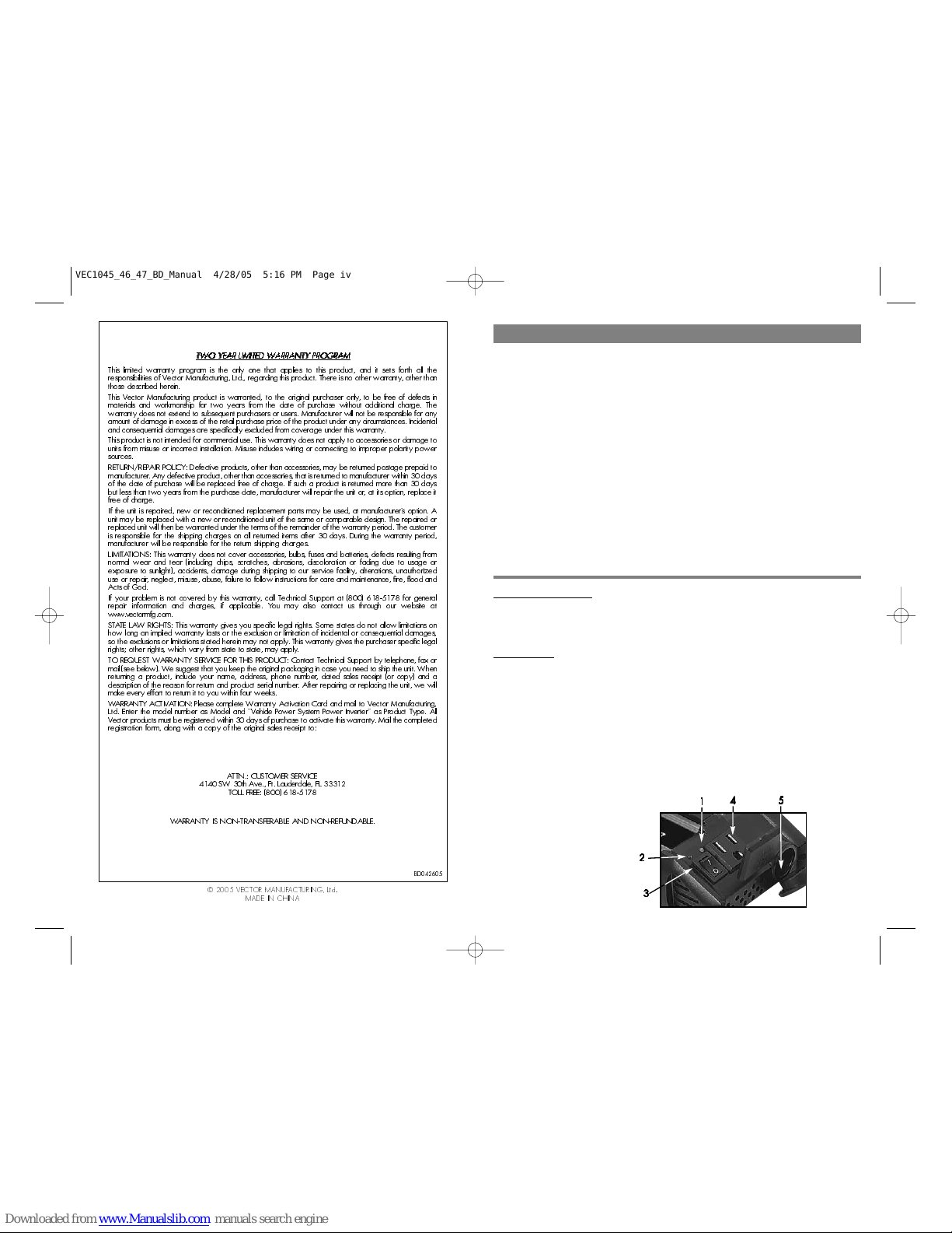
The front panel provides two LED indicators. The green LED indicates power and
proper operation of the inverter, the red LED indicates inverter shutdown from overload or over-temperature condition, or abnormal input voltages.
An ON/OFF Switch turns the inverter ON and OFF. The switch can also be used to
force reset of inverter circuits by switching it OFF, then back ON again.
AC power is supplied through grounded standard North American household-type
outlets. The VEC1045BD features one outlet; the VEC1046BD and VEC1047BD
feature two. The outlets can accommodate either two- or three-pin AC plugs. Power
may also be supplied through the 12 volt DC outlet on the VEC1045BD (only).
Figure 1. VEC1045BD Front Panel
1. Warning LED
2. Power LED
3. ON/OFF Switch
4. AC Outlet
5. 12 Volt DC Outlet
11
11
44
44
55
55
22
22
33
33
TTTTWWWWOOOOYYYYEEEEAAAARRRRLLLLIIIIMMMMIIIITTTTEEEEDDDDWWWWAAAARRRRRRRRAAAANNNNTTTTYYYYPPPPRRRROOOOGGGGRRRRAAAAMM
MM
This limited warranty program is the only one that applies to this product, and it sets forth all the
responsibilities of Vector Manufacturing, Ltd., regarding this product. There is no other warranty, other than
those described herein.
This Vector Manufacturing product is warranted, to the original purchaser only, to be free of defects in
materials and workmanship for two years from the date of purchase without additional charge. The
warranty does not extend to subsequent purchasers or users. Manufacturer will not be responsible for any
amount of damage in excess of the retail purchase price of the product under any circumstances. Incidental
and consequential damages are specifically excluded from coverage under this warranty.
This product is not intended for commercial use. This warranty does not apply to accessories or damage to
units from misuse or incorrect installation. Misuse includes wiring or connecting to improper polarity power
sources.
RETURN/REPAIR POLICY: Defective products, other than accessories, may be returned postage prepaid to
manufacturer.Any defective product, other than accessories, that is returned to manufacturer within 30 days
of the date of purchase will be replaced free of charge. If such a product is returned more than 30 days
but less than two years from the purchase date, manufacturer will repair the unit or, at its option, replace it
free of charge.
If the unit is repaired, new or reconditioned replacement parts may be used, at manufacturer’s option. A
unit may be replaced with a new or reconditioned unit of the same or comparable design. The repaired or
replaced unit will then be warranted under the terms of the remainder of the warranty period. The customer
is responsible for the shipping charges on all returned items after 30 days. During the warranty period,
manufacturer will be responsible for the return shipping charges.
LIMITA TIONS: This warranty does not cover accessories, bulbs, fuses and batteries, defects resulting from
normal wear and tear (including chips, scratches, abrasions, discoloration or fading due to usage or
exposure to sunlight), accidents, damage during shipping to our service facility, alterations, unauthorized
use or repair, neglect, misuse, abuse, failure to follow instructions for care and maintenance, fire, flood and
Acts of God.
If your problem is not covered by this warranty, call Technical Support at (800) 618-5178 for general
repair information and charges, if applicable. You may also contact us through our website at
www.vectormfg.com.
STATE LAW RIGHTS: This warranty gives you specific legal rights. Some states do not allow limitations on
how long an implied warranty lasts or the exclusion or limitation of incidental or consequential damages,
so the exclusions or limitations stated herein may not apply. This warranty gives the purchaser specific legal
rights; other rights, which vary from state to state, may apply.
TO REQUEST WARRANTY SERVICE FOR THIS PRODUCT: Contact Technical Support by telephone, fax or
mail (see below). We suggest that you keep the original packaging in case you need to ship the unit. When
returning a product, include your name, address, phone number, dated sales receipt (or copy) and a
description of the reason for return and product serial number. After repairing or replacing the unit, we will
make ever y effor t to return it to you within four weeks.
W ARRANTY ACTIVATION: Please complete Warranty Activation Card and mail to Vector Manufacturing,
Ltd. Enter the model number as Model and “Vehicle Power System Power Inverter” as Product Type. All
Vectorproducts must be registered within 30 days of purchase to activate this warranty. Mail the completed
registration form, along with a copy of the original sales receipt to:
ATTN.: CUSTOMER SERVICE
4140 SW 30th Ave., Ft. Lauderdale, FL 33312
TOLL FREE: (800) 618-5178
WARRANTY IS NON-TRANSFERABLE AND NON-REFUNDABLE.
BD042605
© 2005 VECTOR MANUFACTURING, Ltd.
MADE IN CHINA
VEC1045_46_47_BD_Manual 4/28/05 5:16 PM Page iv
Page 4
3
The modified sine wave produced by the Power Inverter has an RMS (root mean
square) voltage of 115 volts, which is the same as standard household power. Most
AC voltmeters (both digital and analog) are sensitive to the average value of the
waveform rather than the RMS value. They are calibrated for RMS voltage under the
assumption that the waveform measured will be a pure sine wave. These meters will
not read the RMS voltage of a modified sine wave correctly. They will read about 20
to 30 volts low when measuring the output of the inverter. For accurate measurement
of the output voltage of this unit, use a true RMS reading voltmeter such as a Fluke
87, Fluke 8060A, Fluke 77/99 series, Beckman 4410, or Triplett 4200.
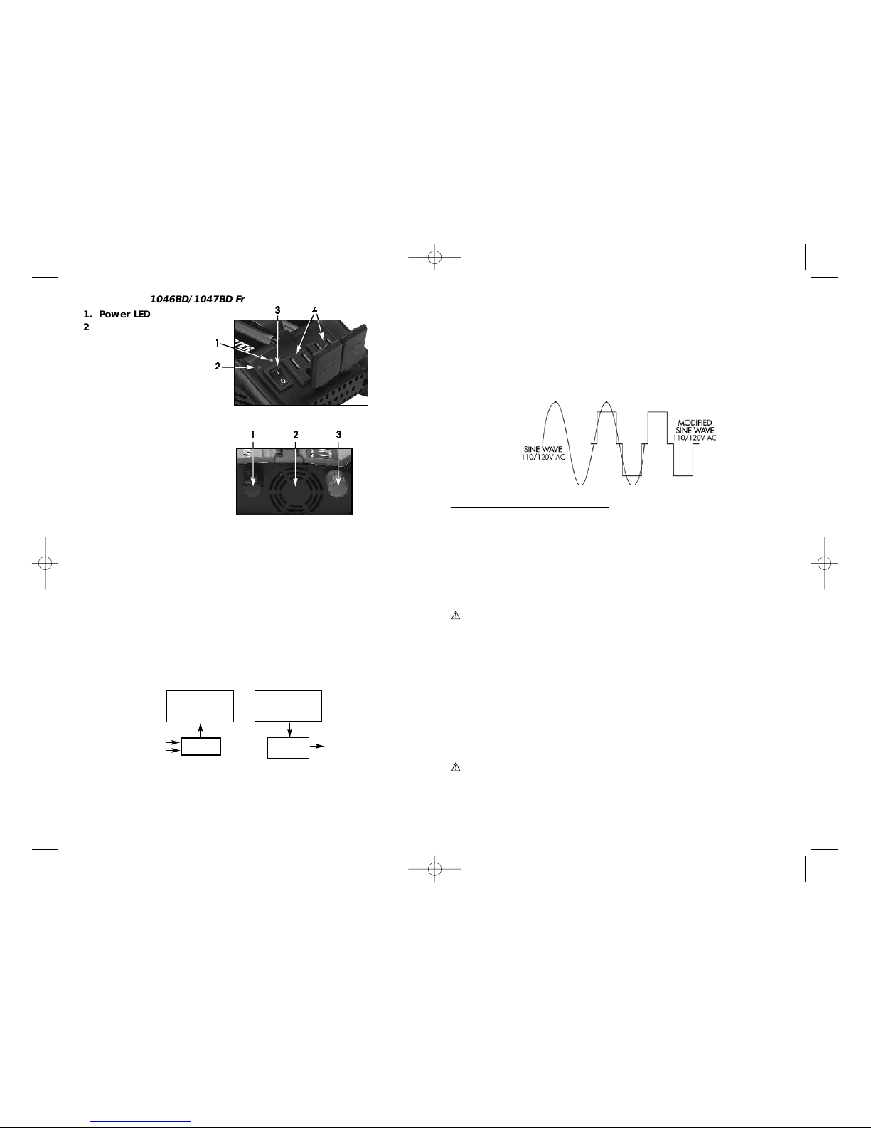
Modified Sine Wave and Sine Wave Comparison
OPERATING INSTRUCTIONS
Power Source Requirements
The power source must provide 12.5 volts DC and must be able to supply the
necessary current to operate the load. The power source may be a battery or a wellregulated DC power supply. To obtain a rough estimate of the current (in amperes)
the power source must deliver, simply divide the power consumption of the load (in
watts AC) by 10.
Example: If a load is rated at 200 watts AC, the power source must be able to deliver:
200 divided by 10 = 20 amperes
CAUTION
The Power Inverter must be connected only to batteries with a nominal
output voltage of 12 volts. The unit will not operate from a 6 volt
battery and will sustain permanent damage if connected to a 24 volt
battery.
Connection to Power Source
The Power Inverter comes equipped with a DC accessory outlet plug and battery clip
cables for connection to a power source (Models 1045BD and 1046 BD only).
Connecting to a Power Source Using the Accessory Outlet Plug
The DC accessory outlet plug is suitable for operating the inverter at power outputs up
to 100 watts. The tip of the plug is POSITIVE (+) and the side contact is NEGATIVE (–).
Connect the inverter to the power source by inserting the DC accessory outlet plug
firmly into the accessory outlet of a vehicle or other DC power source.
CAUTIONS
• Connect directly to power source when operating above 100 watts.
• Do not use with positive ground electrical systems.
• Reverse polarity connection will result in a blown fuse and may
cause permanent damage to the inverter.
2
HOW THIS INVERTER WORKS
The inverter converts low voltage DC (direct current) from a battery or other power
source to standard 120 volt AC (alternating current) household power.
Principle of Operation
The inverter converts power in two stages. The first stage is a DC-to-DC conversion
process that raises the low voltage DC at the inverter input to 145 volts DC. The
second stage is the actual inverter stage that converts the high voltage DC into 115
volts, 60 Hz AC.
The DC-to-DC converter stage uses modern high frequency power conversion
techniques that have replaced the bulky transformers found in less technologicallyadvanced models. The inverter stage uses advanced power MOSFET transistors in a
full bridge configuration. This ensures excellent overload capability and the ability to
operate reactive loads like small induction motors.
The Power Inverter Output Waveform
The AC output waveform of the Power Inverter is known as “modified sine wave.” It
is a waveform that has characteristics similar to the sine wave shape of utility power.
This type of waveform is suitable for most AC loads, including linear and switching
power supplies used in electronic equipment, transformers, and motors.
12VDC to
145VDC
CONVERSION
145VDC to
115VAC
CONVERSION
Internal
Fuses
Two AC
Outlets
12VDC
Input
115VAC, 60Hz
to AC appliances
Figure 4. Rear Panel (All Models)
1. Negative (–) DC
Power Connection
2. High-Speed Cooling Fan
3. Positive (+) DC
Power Connection
22
22
33
33
11
11
1. Power LED
2. Warning LED
3. ON/OFF Switch
4. AC Outlets
22
22
11
11
44
44
33
33
Figure 2. VEC1046BD/1047BD Front Panel
VEC1045_46_47_BD_Manual 4/28/05 5:16 PM Page 2
Page 5

5
Short Circuit Protection —
Reverse polarity or short circuit condition may cause
external or internal fuses to open and may cause irreversible damage to the Power
Inverter. Take extra care to insure a proper polarity hook-up.
Overload Protection —
The unit will automatically shut down when the continuous
draw exceeds the unit’s rated output. The unit should automatically restart after a
shutdown due to overloading once the load is reduced. If it fails to do so, manually
reset using the inverter’s ON/OFF switch.
Over Temperature Protection —
If the temperature inside the Power Inverter reaches
150°F, the unit will automatically shut down. Allow the unit to cool for at least 15
minutes before restarting after a heat-related shutdown. Unplug unit while cooling.
If the low voltage alarm sounds when the battery is fully charged, follow the steps for
solving lack of output power in the Troubleshooting section of this manual. The alarm
will sound if there is an excessive voltage drop between the battery and the inverter.
Note:
It is normal for the alarm to sound while the unit is being connected to, or
disconnected from, the power source. This is not indicative of a problem.
Connecting to a Power Source Using the Provided Cables
Use the provided cables and connect the Power Inverter directly to the 12 volt power
source as follows:
1. Make sure the Power Inverter power is turned OFF and that no flammable fumes
are present in the installation area.
2. Connect the RED cable to the RED post marked (+) on the back of the inverter .
Connect the battery clip to the POSITIVE terminal of the battery.
3. Connect the BLACK cable to the BLACK post marked (–) on the back of the
inverter. Connect the battery clip to the NEGATIVE terminal of the battery.
4. Make sure that all connections between battery clips and terminals are secure.
Direct Hardwiring to Power Source
Use #12 AWG wire if the inverter to power source connection is 4 feet or less. For
longer cable lengths use #8 AWG wire for lengths to 10 feet. In either case, protect
the positive (+) wire from shorts by installing a 50 to 75 Amp fuse or circuit breaker
close to the DC power source (battery) terminal.
1. Check to be sure the inverter’s power switch is turned off and that no flammable
fumes are present.
2. Identify the POSITIVE (+) and NEGATIVE (–) DC power source (battery) terminals.
3. Install a fuse holder or breaker close to the POSITIVE (+) terminal of the DC source
(battery).
4. Connect a length of wire on one side of the fuse holder or circuit breaker.
Connect the other end of the wire to the POSITIVE (+) terminal of the inver ter.
5. Connect a length of wire between the inverter’s NEGATIVE (–) terminal and the
DC power source NEGATIVE (–-) terminal.
6. Connect a short length of wire to the other terminal of the fuse holder or circuit
breaker. Mark it “POSITIVE” or “+”.
7. Connect the free end of the fuse or breaker wire to the POSITIVE (+) terminal of
the DC power source (battery).
8. Insert a fuse appropriate to the inverter in the fuse holder.
4
Notes:
Most vehicle accessory outlet circuits have fuses rated at 15 to 20 amps or
greater. To operate at full wattage, either use the battery clip cable (supplied)
or directly wire to the power source with user-supplied wire and fuse.
The majority of modern automobiles, RVs and trucks are negative ground.
Run Times
The Power Inverter may be used whether or not the vehicle’s engine is running.
However, the inverter may not operate while the engine is starting since the battery
voltage can drop substantially during cranking.
The unit draws less than 0.5 ampere from the battery when it is not supplying power
to a load and switch is in ON position. In most instances, it can be left connected to
the battery when not in use, since it draws so little current. However, if the vehicle is
to remain unused for several days, disconnect the Power Inverter from the battery.
Rated Versus Actual Current Draw of Equipment
Most electrical tools, appliances and audio/video equipment have labels that
indicate the power consumption in amps or watts. Be sure that the power consumption
of the item you wish to operate is rated at or lower than the inverter’s output rating.
If the power consumption is rated in amps AC, simply multiply by the AC volts (115)
to determine the wattage. The Power Inverter has overload protection, and will shut
down if it is overloaded.
Resistive loads are the easiest for the Power Inverter to run. However, larger resistive
loads, such as electric stoves or heaters, usually require more wattage than the Power
Inverter can deliver on a continuous basis. Inductive loads, such as TV’s and stereos,
require more current to operate than do resistive loads of the same wattage rating.
Induction motors, as well as some televisions, may require 2 to 6 times their wattage
rating to start up. The most demanding appliances are those that start under load,
such as compressors and pumps. Testing is the only way to determine whether a
specific load can be started and how long it can run. The unit will simply shut down
if it is overloaded.
The unit should automatically restart after a shutdown due to overloading once the
load is reduced. If it fails to do so, manually reset using the inverter’s ON/OFF switch.
CAUTION
This inverter will not operate high wattage appliances or equipment
that produce heat, such as hair dryers, microwave ovens, and
toasters.
Protective Features of the Inverter
The Power Inverter monitors the following potentially hazardous conditions:
Low Battery Voltage —
This condition is not harmful to the inverter, but could damage
the power source. An alarm will sound when input voltage drops to 11.0 Volts. The
Power Inverter automatically shuts down when input voltage drops to 10 volts. When
the condition is corrected, the inverter can be turned off, then turned back on.
Over Voltage Protection —
The Power Inverter will automatically shutdown when the
input voltage exceeds 15.5 volts DC ± .5 volt DC.
VEC1045_46_47_BD_Manual 4/28/05 5:16 PM Page 4
Page 6

7
This problem does not occur with most battery-operated equipment.
Most of these devices use a separate charger or transformer that is
plugged into an AC receptacle. The Power Inverter is easily capable of
running most chargers and transformers.
CARE AND MAINTENANCE
Storage
1. Ideal storage temperature range is 50-68°F (10-20°C).
2. Store and use the inverter in a cool, dry place with adequate ventilation.
3. Avoid locations that are exposed to heating units, radiators, direct sunlight or
excessive humidity or dampness.
Fuse Replacement
This inverter is equipped with multiple internal fuses. Normally, these fuses will not
“blow” unless there is a serious problem inside the unit. Internal fuses are
replaceable; however, only trained personnel should attempt fuse replacement. If the
unit is damaged during fuse replacement, the warranty may be voided. The
manufacturer recommends contacting Technical Support at (800)-618-5178.
TROUBLESHOOTING
Common Audio/Visual Problems
“Buzzing” sound in audio systems
Some inexpensive stereo systems and “boom boxes” emit a buzzing sound from their
speakers when operated from the Power Inverter. This occurs because the power
supply in the electronic device does not adequately filter the modified sine wave
produced by the inverter. The only solution to this problem is to use a higher quality
sound system that incorporates a higher quality power amplified supply.
Television Interference
The Inverter is shielded to minimize interference with TV signals. However, in some
instances, some interference may still be visible, particularly with weak TV signals. Try
the following corrective measures:
• Position the inverter as far as possible from the television, the antenna and the
antenna cables. Use an extension cable, if necessary
• Adjust the orientation of the inverter, the antenna cables and the TV power cord to
minimize interference
• Make sure that the antenna feeding the television provides an adequate (“snow
free”) signal and that high quality, shielded antenna cable is used
6
9. Test the inverter by turning it on and plugging in a 100 watt lamp or equipment.
10. If the inverter is not properly operating, then refer to the Troubleshooting section
of this manual.
CAUTION
•Loose connectors may cause overheated wires and melted
insulation.
• Check to make sure you have not reversed the polarity. Damage due
to reversed polarity is not covered by our warranty.
Connection To Load
The Power Inverter is equipped with dual standard North American AC power
receptacles. Plug the cord from the equipment you wish to operate into the AC
receptacle(s). Make sure the combined load requirement of your equipment does not
exceed maximum continuous power.
The Power Inverter is engineered to be connected directly to standard electrical and
electronic equipment in the manner described above. Do not connect the Power
Inverter to household or RV AC distribution wiring. Do not connect the Power Inverter
to any AC load circuit in which the neutral conductor is connected to ground (earth)
or to the NEGATIVE of the DC (battery) source.
WARNING
Do not connect to AC distribution wiring!
Operating Tips
For best operating results, the inverter should be placed on a stable, flat surface. A
power cord measuring 2 feet (0.61 meters) has been provided for easy positioning
of the inverter. (VEC1045/46 features a clip cable of 0.9 meter, vehicle accessory
plug cable of 0.6 meter; VEC1047 features a clip cable of 0.9 meters only.)
The inverter should only be used in locations that meet the following criteria:
DRY — Do not allow water or other liquids to come into contact with the inverter.
COOL — Surrounding air temperature should be between –0°C and 40°C — ideally
between 15°C and 25°C (60-80°F). Keep the inverter away from direct sunlight,
when possible.
WELL-VENTILATED — Keep the area surrounding the inverter clear to ensure free air
circulation around the unit. Do not place items on or over the inverter during
operation. The unit will shut down if the internal temperature gets too hot.
SAFE — Do not use the inverter near flammable materials or in any locations that may
accumulate flammable fumes or gases. This is an electrical appliance that can briefly
spark when electrical connections are made or broken.
CAUTION
Rechargeable Devices
Certain rechargeable devices do not operate well from a modified sine
wave inverter. They only operate properly fr om a standard household
outlet, which provides a pure sine wave. Therefore, the manufacturer
recommends that these types of devices be operated from a standard
household outlet only, not from the inverter.
VEC1045_46_47_BD_Manual 4/28/05 5:16 PM Page 6
 Loading...