

Page 1
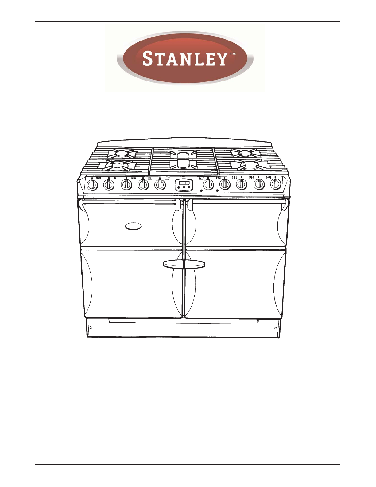
Supreme DF
User's Manual
&
Installation and Servicing Instructions
PLEASE READ THESE INSTRUCTIONS BEFORE USING THIS APPLIANCE
06/10 EINS 514896
REMEMBER, when replacing a part on this appliance, use only spare parts that you can be assured conform to the safety
and performance specification that we require. Do not use reconditioned or copy parts that have not been clearly
authorised by Waterford Stanley.
Page 2

Be safe
Warning
Accessible parts will become hot in use. To avoid burns and scalds children should be kept away.
You need clean fresh air - so does your cooker. Burner flames produce exhaust gases, heat and moisture. Make sure
that the kitchen is well ventilated: keep natural ventilation holes open or install a powered cooker hood that vents
outside. If you have several burners on or use the cooker for a long time, open a window or turn on an extractor fan.
For more detail see the Installation Instructions.
We recommend you read the 'General Safety Instructions' section if you have not used a gas cooker before.
We describe some basic guidelines on how to use a gas cooker safely.
Gas and Electricity
Make sure that the gas supply is turned on and that the cooker is wired in and switched on. The cooker needs electricity .
Peculiar smells
When you first use your cooker it may give off a slight odour and a little smoke. This is normal and harmless (from oven
lagging and starch binder on the element insulation) and will cease after a short period of use.
2
Page 3

3
Contents
Users Guide
Setting up the Cooker for Use Page 4
Hotplate Burners Page 5
The Slow Cooking Oven Page 6
Ideas for the Slow Cooking Oven Page 7
The Grill (Top Right) Page 12
The Fan Ovens Page 13
Oven Cooking Guide Page 14
Fan Oven Cooking Chart Page 16
The Automatic Cooking Control Page 17
Cleaning the Cooker Page 20
Troubleshooting Page 24
General Safety Instructions Page 26
Installation Guide
Installation Page 28
Servicing Page 35
Circuit Diagram Page 39
Technical Data Page 40
Page 4
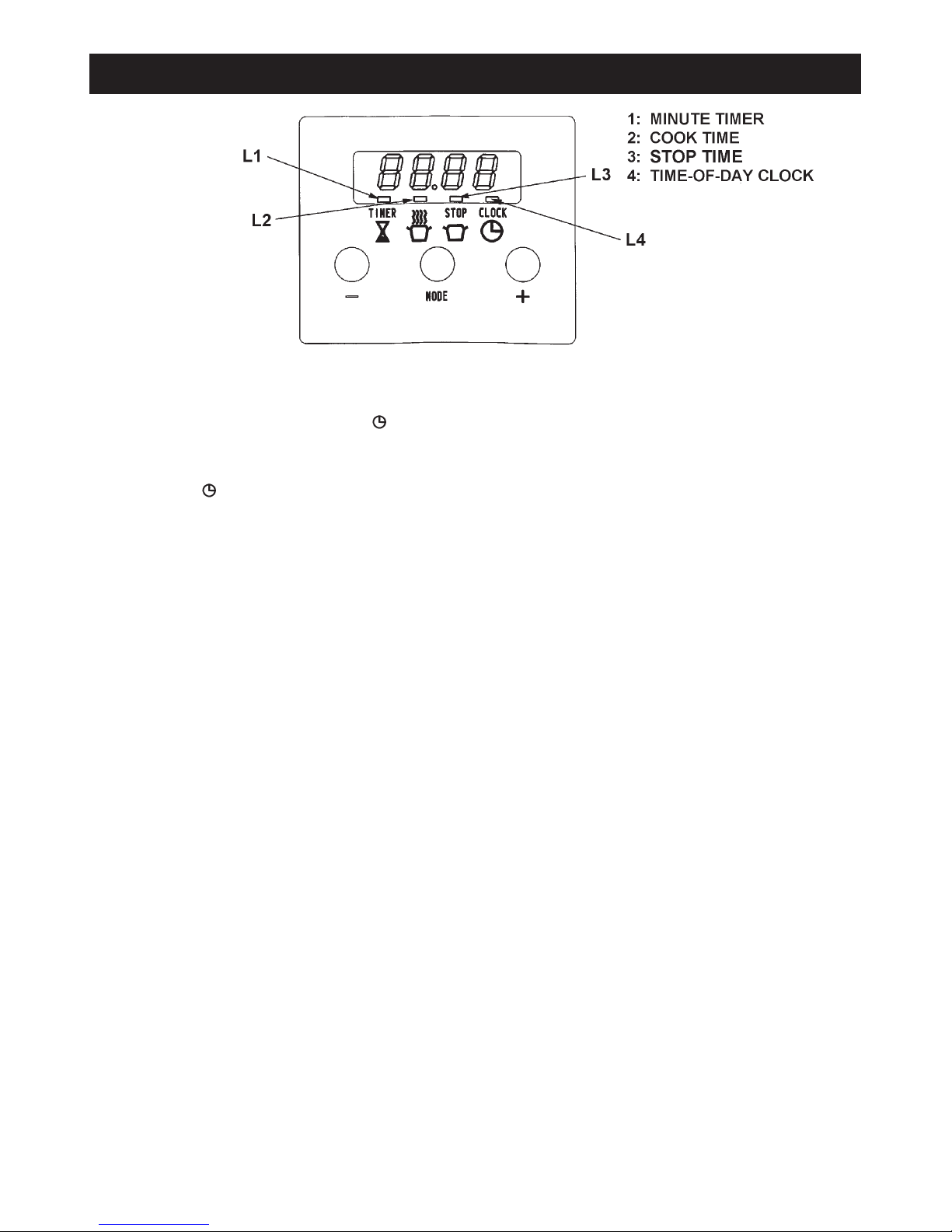
Before the fan oven can be used, it will be necessary to set the ‘time-of-day-clock’.
This is a 24-hour clock, and when the power supply is initially switched on, or after an interruption in supply, the clock will
show 12.00 and the L 4 will flash above the sign.
SETTING THE TIME OF DAY
1. Whilst the L 4 is flashing, press the plus + and/or minus buttons until the display shows the correct time of
day.
2. After 5 seconds, the L4 will stop flashing.
The setting can be altered at any time by using the MODE button until the L 4 flashes and pressing the plus + and minus
- buttons.
The cooker is now ready for use.
Setting up the cooker for use
4
Page 5
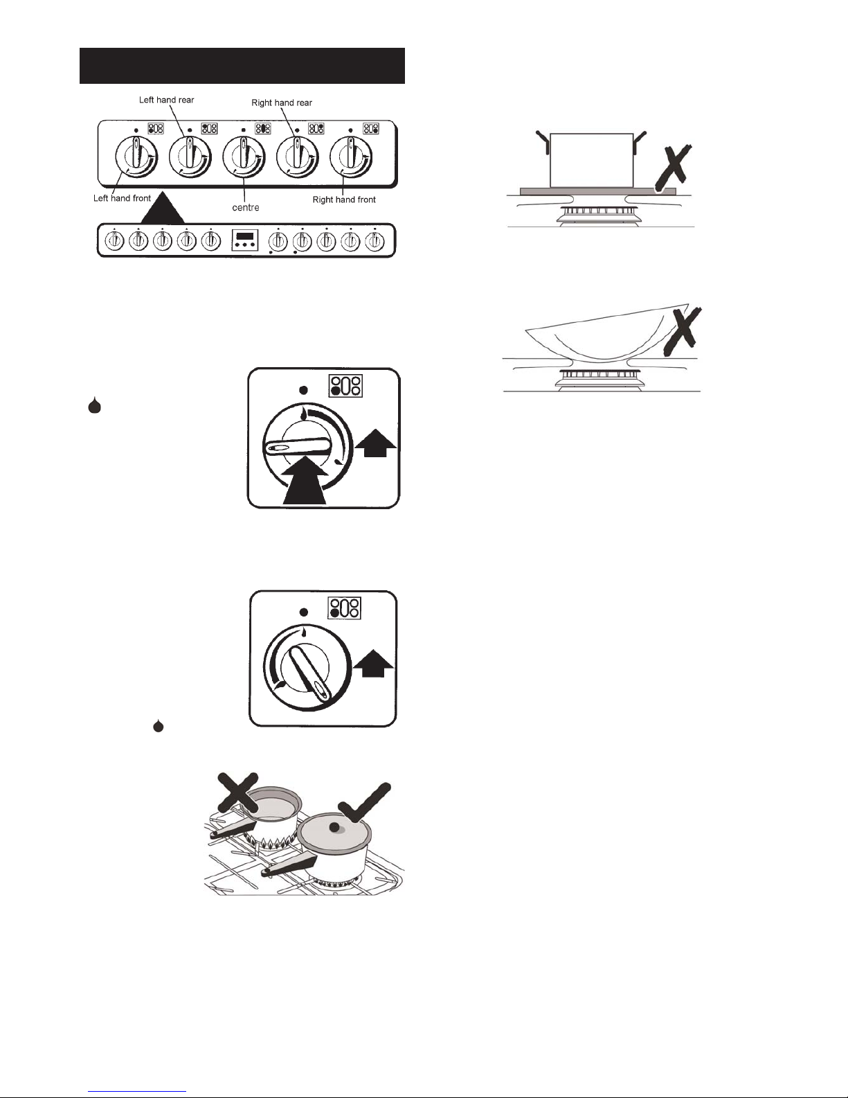
The drawing above each knob indicates which burner that
knob controls. There is a spark ignition system that works
when the knob is pressed in. Each burner also has a
special safety device that stops the flow of gas if the flame
goes out.
Push in and turn a knob to
the large flame symbol
( ).
Keep holding the knob
pressed in to let the gas
through to the burner for a
few seconds. The igniter will
spark and light the gas
automatically.
If, when you let go of the control knob, the burner goes
out, the safety device has not held in. Turn the control to
the off position and wait one minute, then try again this
time holding in the control
knob for slightly longer.
Adjust the flame height to
suit by turning the knob.
On this cooker the low
position is beyond high, not
between high and off. The
small flame ( ) marks the
‘low position’.
Turn the knob
towards it after the
contents of a pan
have boiled.
Place all pans
centrally over the
burners. The flames
must be on the base
of the pan. Do not allow the flames to go up the sides of
the pan.
Using a lid will help the contents boil more quickly.
Always position pan handles away from the front of the
cooker, out of reach of small children.
Pan and kettles with concave bases or down turned base
rims should not be used.
Simmering aids, such as asbestos or mesh mats, are NOT
recommended. They will reduce burner performance and
could damage the pan supports.
Avoid using unstable and misshapen pans that may tilt
easily and pans with a very small base diameter e.g. milk
pans, single egg poachers.
Do not use oversized pans that overhang the edges of the
pan supports.
Minimum pan sizes
The minimum pan diameter recommended is 120mm
(about 4
3
/4
”).
When the hotplate control knob is pressed in, sparks will
be made at every burner, this is normal.
If, after lighting the hotplate burner flame goes out, turn it
off and leave it for one minute before relighting it.
IMPORTANT: The cast iron pan supports on the
appliance are of a professional design and much
heavier than most if not all gas hob cookers.
Therefore care must be taken when removing or refitting them from or to the hob. It is important that they
are lifted from the appliance. Do not drag them across
adjacent enamelled components as this could
damage the enamel.
Y ou can remove the burner head for cleaning. See the
‘Cleaning your cooker’ section of these instructions
for removal and fitting of the pan supports and burner
parts.
You should wipe the top surface of the cooker around the
hotplate burners as soon as possible after spills occur. Try
to wipe them off while the hotplate is still warm.
5
Hotplate Burners
Page 6

Deep Fat Frying
z
Use a deep pan large enough to completely cover the
appropriate heating area.
z
Never fill the pan more than one-third full of fat or oil.
z
Never leave fat or oil unattended during the heating or
cooking period.
z
Never use a lid on the pan.
z
IMPORTANT: Oil is a fire risk; do not leave pans
containing oil unattended.
z
In the event of fire cover with a lid and turn OFF the
appliance.
Do not attempt to extinguish the fire using water.
Smother the flames on the hob rather than attempting to
remove the pan to the outside.
Burns and injuries are caused almost invariably by picking
up the burning pan to carry outside.
z
Do not try to fry too much food at a time, especially
frozen food. This only lowers the temperature of the oil
or fat too much, resulting in greasy food.
z
Always dry food thoroughly before frying and lower it
slowly into the hot oil or fat. Frozen foods in particular,
will cause frothing or spitting, if added to quickly.
z
Keep the outside of the pan, clean and free from
streaks of oil or fat.
NOTE: Use of aluminium pans may cause metallic
marking of the pan supports. This does not affect the
durability of the enamel and may be cleaned off with a
metal cleaner such as ‘Brasso’ or an enamel rubber.
Fish Kettle Burner
The central hotplate burner can be used to cook whole
salmon, trout, etc. in a fish kettle.
Suggested Method for cooking whole Salmon
Place the gutted and cleaned fish, with or without head
and tail in to the kettle with sufficient water to almost cover
the fish. Season with salt and pepper and add a few
pieces of carrot, onion and parsley to give flavour. Bring to
the boil, covered and simmer for 8 - 10 mins per 450g (1
lb).
When cooked, leave to cool in the liquid before draining,
and removing the skin. Decorate as desired.
6
Page 7
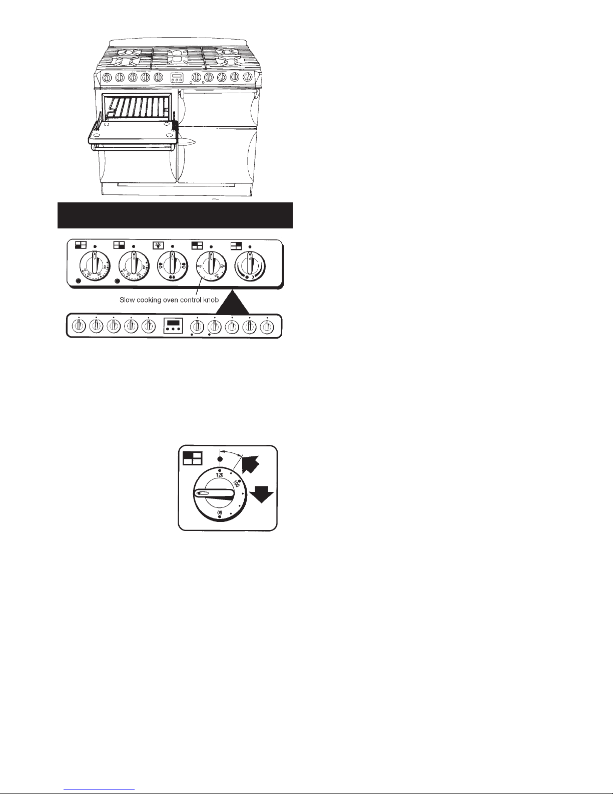
This oven is for long, slow cooking over 6-8 hours,
keeping food warm and warming plates for short periods.
Extra care must be taken when warming bone china use the lowest setting.
Using the Slow Cooking Setting
The slow cooking setting
is in the area marked
between 110° - 120°C
on the oven control knob.
The Slow Cooking oven has side panels that are coated
with a special enamel that partly cleans itself. For more on
cleaning the ovens see the ‘Cleaning your cooker’ section
of these instructions.
Points to bear in mind when preparing food.
Do not place dishes directly on to the oven base. Always
place onto shelf supplied.
The shelf is designed to lock in place, but is removable for
cleaning. See the ‘Cleaning your cooker’ section of these
instructions.
Push dishes well back in the oven to ensure that they are
positioned over the element beneath the base plate.
Make sure all dishes will fit into the oven before preparing
the food.
All dishes cooked by the slow cooking method should be
cooked for a minimum of 6 hours. They will ‘hold’ at this
setting for a further 1-2 hours but marked deterioration in
appearance will be noticed in some cases.
Joints of meat and poultry should be cooked at 180°C for
30 minutes before transferring to the slow cooking oven.
Meat over 2.7 kg (6lbs) and poultry over 2kg (4lbs 8ozs)
are unsuitable for the slow cooking method.
Always stand covered joints on a rack over a meat tin, to
allow good air circulation.
Make sure that pork and poultry reach an internal
temperature of at least 90°C.
Slow cooking is unsuitable for stuffed meat and poultry.
Always brings soups, casseroles and liquids to the boil
before putting in the oven. When casseroles are used,
cover the food first with foil and then the lid to prevent loss
of moisture.
Always thaw frozen foods completely before cooking.
Root vegetables will cook better if cut into small pieces.
Adjust seasonings and thickenings at the end of the
cooking time.
Egg and fish dishes need only 1-5 hours cooking and
should be included in day cooking sessions, where they
can be observed from time to time.
Dried red kidney beans must be boiled for a minimum of
ten minutes, after soaking, and before inclusion in any
dish.
Storage and Re-Heating of Food
If food is to be frozen or not served immediately, cool it in
a clean container as quickly as possible.
Thaw frozen food completely in the refrigerator before reheating.
Re-heat food thoroughly and quickly either on the hotplate
or in a hot oven 200°C (180°C fan oven), and then serve
immediately.
The Slow Cooking Oven
7
Page 8

Many favourite recipes can be adapted for this type of cooking:
Slow Cooking Oven Recipes - Meal 1
6 - 8 hours cooking time
Ragout of Beef in Ale
Baked Potatoes
Rice Pudding
Ingredients Method
* If cooking for 8 hours or more use 40g (1 1/2
oz) rice only
Ideas for the Slow Cooking Oven
Ragout of Beef in Ale
Baked Potatoes
Rice Pudding
30ml (2tbsps) oil
675g (1
1
/
2 lbs) chuck steak, cubed
1 clove of garlic, crushed
2 carrots, sliced
100g (4oz) mushrooms, quartered
2 medium onions, sliced
40g (1
1
/2 ozs) plain flour
5ml (1 tsp) coarse-grained mustard
10ml (1 dsp) Demerara sugar
30ml (2tbsps) tomato purée
450ml (
3
/4 pt) brown ale
salt and freshly ground pepper
4 medium sized potatoes
*40-50g (1
1
/2 - 2 ozs) pudding rice
25g (1oz) sugar
550ml (1 pt) milk
nutmeg
knob of butter
25g (1oz) sultanas (optional)
1. Sauté the meat in a casserole in hot oil until brown.
Remove.
2. Sauté the garlic, onions, carrots and mushrooms until
brown.
3. Stir in flour and mix well.
4. Add mustard, sugar and tomato purée.
5. Stir in the ale and seasoning. Return meat.
6. Bring to the boil and cover. Transfer to the oven.
1. Wash and prick well all over.
2. Wrap in one layer of foil.
3. Place directly on the shelf in between the casserole
and rice pudding.
1. Wash the rice in cold water and place in an 850ml (1
1
/2 pt) pie dish.
2. Add the sugar, milk and sultanas if using.
3. Sprinkle with nutmeg and add a good knob of butter.
8
Page 9

Slow Cooking Oven Recipes - Meal 2
6 - 8 hours cooking time
Roast Fillet of Lamb
Dauphinoise Potatoes
Bread and Butter Pudding
Ingredients Method
Roast fillet of Lamb
Dauphinoise Potatoes
Bread and Butter Pudding
900g - 1.25 kg (2 - 2
1
/
2lbs) lamb
450g (1 lb) potatoes, thinly sliced
1-2 cloves of garlic, crushed
125ml (
1
/4 pt) double cream
salt and freshly ground black pepper
6-8 medium slices of wholemeal bread
Approx 50g (2ozs) butter, melted
Grated rind of one orange (optional)
25g (1oz) desiccated coconut
50 - 100g (2 - 4oz) luxury/tropical mixed fruit
50g (2oz) soft brown sugar
450ml (
3
/
4 pt) milk
2 eggs
1. Season and wrap the lamb in foil.
2. Stand meat on a rack over a small roasting tin.
1. Grease a shallow oval or rectangular dish.
2. Arrange layers of potatoes, seasoning and garlic in the
dish, ending with potatoes.
3. Pour over the cream and cover well with foil.
1. Grease a shallow oval or rectangular dish.
2. Cut the crusts off the bread and divide into
rectangles/triangles.
3. Dip enough pieces of bread in the butter on one side to
cover the base of the dish, butter side up.
4. Sprinkle with half of the fruit, coconut, sugar and
orange rind.
5. Cover with a second layer of bread dipped in the butter
and then the remaining rind, fruit, coconut and sugar.
6. Whisk the eggs and milk together and pour over the
bread, Stand for
1
/2 hour before baking. Leave
uncovered in the oven.
9
Page 10

Slow Cooking Oven Recipes - Meal 3
6 - 8 hours cooking time
Gammon and Apricot Pie
Braised Red Cabbage
St. Clements Pudding
Ingredients Method
Gammon and Apricot Pie
St Clements Pudding
Braised Red Cabbage
2 gammon rashers approx 15mm (
1
/
2”) thick
100g (4oz) no-soak dried apricots
25g (1oz) sultanas
3 large potatoes, thinly sliced
300ml (
1
/2 pt) chicken stock
50g (2oz) butter, melted
2 rounds of thick sliced wholemeal bread
a little milk
50g (2oz) butter or margarine
50g (2oz) soft brown sugar
grated rind and juice of 1 lemon
grated rind and juice of 1 orange
3 eggs, separated
caster sugar for sprinkling
350g (3/4 lb) red cabbage
25g (1oz) butter
1 medium onion, sliced
1 medium cooking apple, sliced
30ml (2 tbsps) cider vinegar
45ml (3 tbsps) honey
salt and pepper
1. Remove the rind from the gammon. Nick the edges
and lay them in a shallow dish.
2. Sprinkle with apricots, sultanas and pepper.
3. Overlap the sliced potatoes on top of the gammon.
Pour over stock.
4. Brush with melted butter, place in the oven
1. Grease a shallow ovenproof dish and line the base
with fingers of bread.
2. Pour over sufficient milk to be absorbed by the bread.
3. Cream the fat and sugar.
4. Add the yolks, grated rind and juice of orange and
lemon. Beat.
5. Whisk the egg whites stiffly and fold most of them into
the creamed mixture.
6. Spread the mixture over the bread.
7. Finish with a layer of the remaining egg white, thickly
dredged with sugar. Leave uncovered. Place in the
oven.
1. Slice the red cabbage finely.
2. Melt the butter in an oval casserole dish and sauté the
onion and apple until starting to soften.
3. Add the cabbage and cook for a further 2 minutes.
4. Mix in the vinegar, honey and seasoning.
5. Cover with buttered greaseproof paper and a tightly
fitting lid, covered in foil. Place in the oven.
10
Page 11

Slow Cooking Oven Recipes - Meal 4
6 - 8 hours cooking time
Chilli Con Carne
Oven Rice
Frangipane and Apple Pudding
Ingredients Method
Chilli Con Carne
Frangipane and Apple Pudding
Oven Rice
450g (1 lb) minced beef
1 x 400g (14 oz) tin tomatoes
1 x 400g (14oz) tin kidney beans
1 packed Chilli con carne spice mix
100ml (4 fl oz) water
450g (1 lb) cooking apples, grated
50g (2 oz) vanilla fudge, chopped
50g (2 oz) softened butter
50g (2 oz) soft brown sugar
50g (2 oz) ground almonds
12g (
1
/2
oz) plain flour
1 egg
almond essence
225g (8oz) long grain rice
350ml (12 fl ozs) water
seasoning
1. Brown the minced beef in an oval casserole dish.
2. Stir in the spice mix.
3. Add beans drained, tomatoes and water.
4. Mix well together. Bring to boil, cover well and place in
oven.
1. Grease a shallow oven dish.
2. Mix the apples and fudge together and place into the
dish.
3. Cream the rest of the ingredients and add a few drops
of almond essence.
4. Carefully spread over the apple. Leave uncovered and
place in oven.
1. Wash rice and place in an oval casserole dish.
2. Pour on water, seasoning and bring to the boil.
3. Cover well and place in oven.
11
Page 12
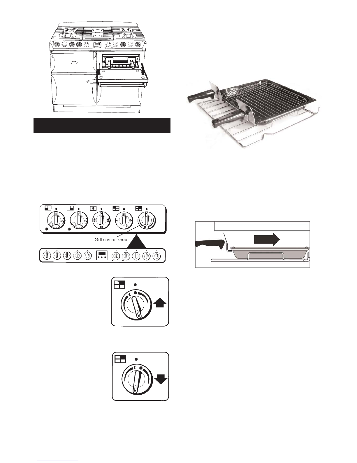
CAUTION: Accessible parts may be hot when the grill
is in use. Young children should be kept away.
If you find a crack in the glass surface of the grill
immediately disconnect the appliance from the electricity
supply. Do not reconnect the appliance until it is repaired.
THE GRILL COMPARTMENT DOOR MUST BE KEPT
OPEN WHEN THE GRILL IS ON.
The very high speed instant grill
is divided into two areas to save
energy and to suit individual
grilling requirements.
Turn the grill control clockwise
and the whole of the grilling
area can be used for large
amounts of food.
For small amounts of food e.g.
2 slices of toast, one or two
chops etc. turn the control anticlockwise. Only the middle
area of the grill heats up.
Most food is cooked at a high setting but for thicker pieces
of meat/poultry and for food such as well done steak the
heat can be reduced by turning the control down to a
lower setting.
For best results pre-heat at a high setting for
approximately 2 minutes.
The grill pan fits on the shelf supplied (shown out of the
grill chamber for clarity).
The shelf is designed to lock in place, but is removable for
cleaning. See the ‘Cleaning the cooker’ section of these
instructions.
Make sure the grill pan is pushed right to the back of the
grill chamber.
Food should be cooked on the grid or in the base of the
grill pan. You can brown the top of dishes, cooked in the
oven, under the grill by placing the dish onto the base of
the grill pan, which can easily slide along the floor of the
grill cavity.
The grill chamber has side panels that are coated with a
special enamel that partly cleans itself. For more on
cleaning the cooker see the ‘Cleaning the cooker’ section
of these instructions.
12
The Grill (Top Right)
Page 13
During use the appliance becomes hot. Care should
taken to avoid touching the heating elements inside
the ovens.
The clock must be set to the time of day before the left
hand oven will work. See ‘Setting up the cooker for
use’ section of these instructions for how to set the
clock.
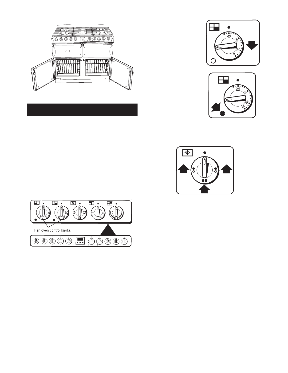
Both the lower ovens are fan ovens. The fans circulate hot
air continuously, which means faster more even cooking.
It is only necessary to pre-heat the ovens for food such as
scones, puff pastry, Yorkshire Pudding, bread etc.
To operate either oven
Before using for the first time, heat the ovens to 200°C for
30 minutes to dispel manufacturing odours.
NOTE: The recommended
cooking temperatures for
fan ovens are generally
lower than non-fanned
ovens. (See Page 16).
Turn the oven temperature
knob to the temperature you
need.
The oven indicator light will
glow until the oven has
reached the temperature
you selected.
It will then cycle on and off
during cooking.
The Oven Lights
Turn the oven light knob to the left for the left hand oven
light and to the right for the right hand oven light. To turn
on both lights turn the knob to the bottom position.
13
The Fan Ovens
Page 14

14
Cooking Hints
When using the fan ovens, reduce conventional oven
settings by 10ºC - 20ºC and cooking time by up to 10
minutes for every hour.
Fan oven cooking is particularly suitable for baking on
several shelves at one time.
The wire shelves should always be pushed firmly to the
back of the oven.
Baking trays, meat tins etc. should be placed level
centrally on the oven shelves. Keep all trays and
containers away from the sides of the oven, as
ovenbrowning of the food may occur.
For even browning, the maximum recommended size of
baking tray is 300mm x 240mm (12” x 9
1
/2”).
When the oven is on, do not leave the door open for
longer than necessary, otherwise the knobs may get very
hot.
Always leave a ‘fingers width’ between dishes on the
same shelf, and between dishes and the sides of the
oven, this allows the heat to circulate freely around them.
The base of a pastry dish can be browned by pre-heating
the baking tray for 15 minutes before placing the dish in
the centre of the tray.
Where dishes may boil and spill over during cooking,
place them on a baking tray.
Please remember that all cookers vary - temperatures in
the new Aga Masterchef ovens may differ to those other
cookers. Settings and cooking times can be changed to
suit individual tastes. It is important to check that food is
piping hot before serving.
The cooking chart is a general guide but times and
temperatures may vary according to individual recipes.
The meat sections should be used as a general guide but
may vary according to the size, shape of joint on or off the
bone.
Thaw frozen joints before cooking them.
The times are for open roasting, If covered allow extra
time.
The turkey/chicken is cooked when the juices run clear
when pierced with a skewer. If the juices are still pink
continue to cook checking every 15 minutes.
Do not place the shelf or food on the base of the ovens.
Steam
When cooking foods with high water content (e.g. oven
chips) there may be some steam visible at the grille at the
rear of the hotplate.
Condensation may form on the cooker. This is quite
normal and nothing to worry about. The condensation
forms when heat and moisture are present. Whenever
possible try to make sure that food which contains a lot of
moisture for example casseroles are covered. If you do
notice any condensation, wipe it up straight away. Do not
leave food in the oven to cool after it has been switched
off.
Cooking high moisture content foods can create a ‘steam
burst’, when the oven door is opened. When opening the
oven stand well back and allow any steam to disperse.
General
The fan ovens are fitted with side, roof and back panels
that are coated with a special enamel that partly cleans
itself. The oven liners (see Cleaning the cooker) work
better when fat splashes are avoided. Cover meat when
cooking.
To reduce fat splashing when you add vegetables to hot
fat around a roast, dry them thoroughly and brush lightly
with cooking oil.
For more on cleaning the ovens see the ‘Cleaning the
cooker’ section of these instructions.
Do not allow young children to stand on the drop
down oven doors.
Oven Cooking Guide
Page 15

The oven control settings and cooking times given in the table are intended to be used
only as a guide. Individual tastes may require the temperature to be altered to provide a
preferred result.
There may be a slight difference in the results between the two ovens. This is due to
manufacturing tolerances and it may be necessary to alter times and temperature settings to
allow for this.
Food is cooked at a lower temperature in a fan oven than in a conventional oven. When using recipes,
reduce the temperature by 10ºC - 20ºC. The temperature in the fan oven does not vary with height
in the oven - so you can use any shelf.
Always leave at least one runner space between shelves when 2 tier cooking. Place baking
trays, individual cake tins or baking dishes on the oven shelf. For best results pre-heat
the oven until the oven indicator light goes out.
15
Page 16
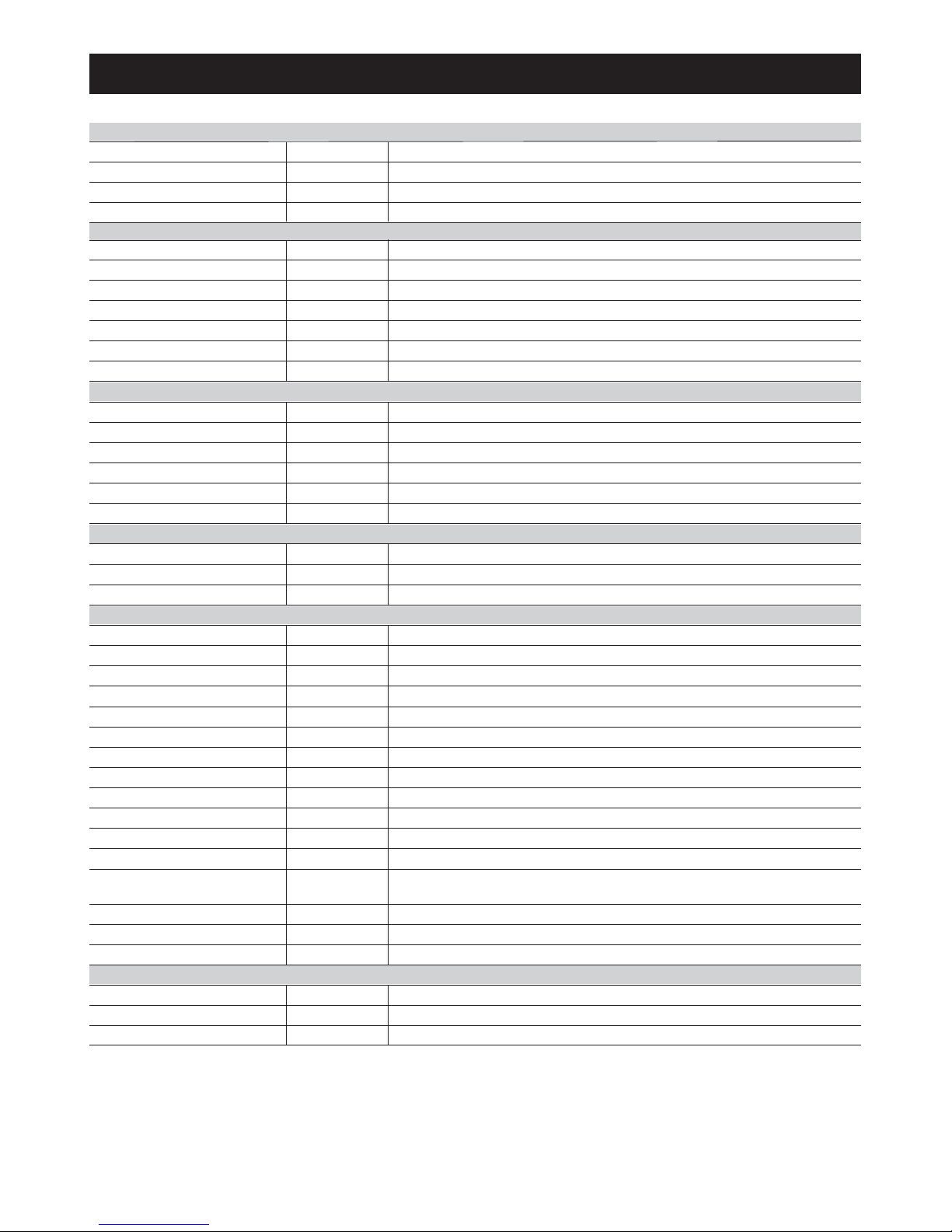
16
FOOD SETTING ºC
170 25 - 30 mins depending on size
APPROXIMATE COOKING TIME
Steaks
Whole Fish e.g. trout, mackerel
170 20 - 25 mins depending on thickness
Oven-fried fish 210 25 mins depending on packet instructions
Salmon (2.7kg) 140 - 150 15 - 18 mins per 450g
170 - 180 30 mins per 450g + 30 mins over (medium rare)Beef
170 - 180
170 - 180
170 - 180
160
25 mins per 450g + 25 mins over
30 - 35 mins per 450g + 35 mins over
Lamb
Chicken
Pork
Turkey
25 mins per lb + 25 mins over
1
1
/
2 - 3 hours depending on recipe
2 hours
35 mins
45 mins - 1 hour using raw fruit
45 mins - 1 hour
Duck & Goose
Casserole
Milk Puddings
Baked Custard
Baked Sponge Pudding
Fruit Crumble
170 - 180
130 -140
140
130
170
170 - 180
45 minsMeringue Toppings 130
3 - 4 hours - Turn meringues over as soon as they are setMeringue 80 - 90
20 - 25 mins per 450g + 20 mins over
15 - 18 mins per 450g + 15 mins over
Fan oven cooking chart
FISH
MEAT & POULTRY
PUDDING
YEAST MIXTURES
CAKES, PASTRIES, BISCUITS & SCONES
MISCELLANEOUS
30 - 45 minsBread - loaves 200 - 210
15 - 20 minsBread - rolls 200 - 210
25 - 35 minsChelsea Buns etc. 180
20 - 25 minsSmall Cakes 170
25 - 30 minsVictoria Sandwich (250mm) 160 - 170
7 - 10 minsSwiss Roll 200
20 minsFatless Sponge (180mm) 170
10 - 15 mins
Scones 200
1 hour - Place on a piece of citron peel after 20 minsMaderia Cake 160
2 - 2
1
/2 hours
Med. Rich Fruit Cake
130
4 - 4
1
/2 hours
Christmas Cake (205mm) 130
1 - 1
1
/
2 hours
Gingerbread 130 - 140
1
1
/
4 - 1
1
/
2 hours
Shortbread 130
15 - 25 mins depending on recipeBiscuits 150 - 170
30 mins - 1
1
/2 hours depending on recipe
Tray Bakes & Tea Breads 160 - 170
Small Tarts 20 - 25 mins depending on recipe
Pies 45 - 50 mins depending on recipe
Shortcrust Pastry 190
25 minsRich Shortcrust Pastry 180
8 - 10 mins depending on recipeFlaky/Puff Pastry
200
25 - 35 minsChoux Pastry 190
45 mins
Yorkshire Pudding - Large
200
20 - 25 mins
Yorkshire Pudding - Individual
200
45 mins
Soufflés
170
Page 17
17
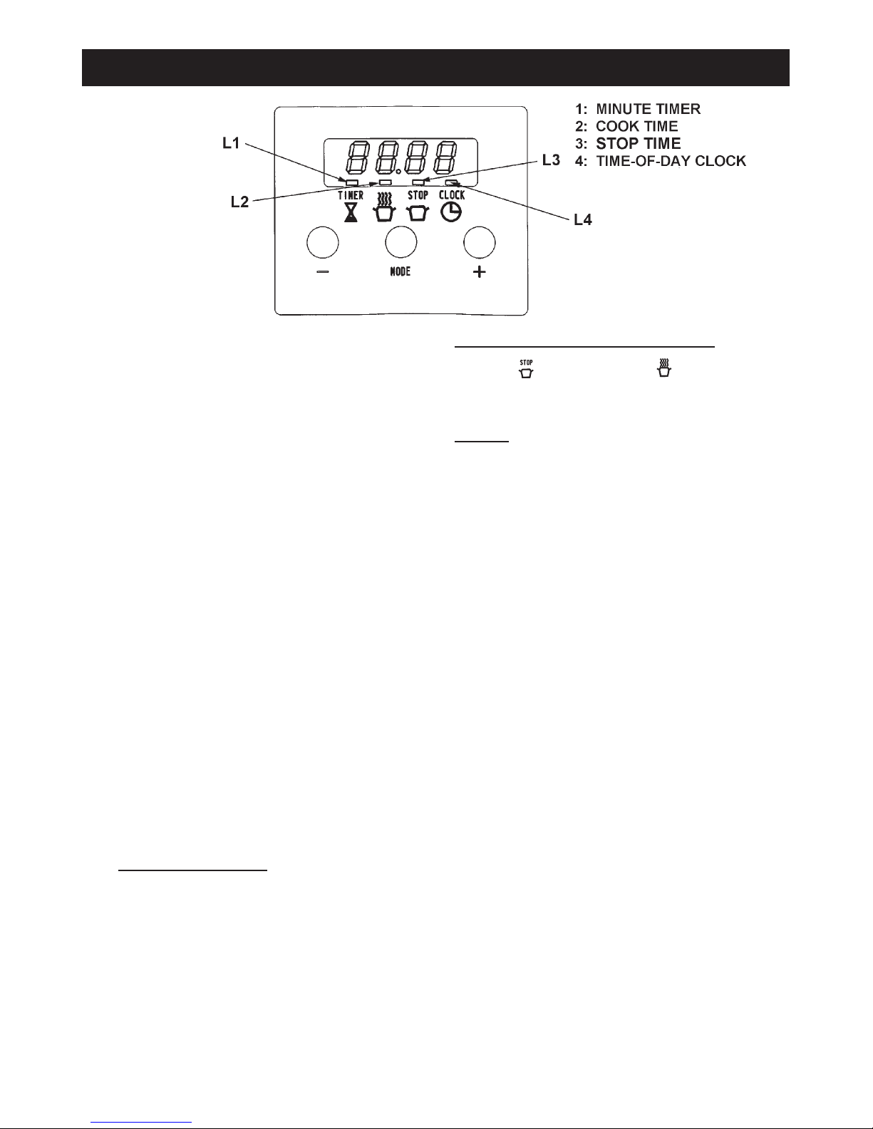
This control includes a minute timer, a time-of-day clock
as well as an automatic cooking control.
There are three buttons which operate the timer.
The buttons are used for the the following purposes.
By using these buttons the following functions can be
selected:
z Minute timer
z Automatic cooking time
z End of automatic cooking time
z Time-of-day clock
Every time the MODE buttons is pressed a small LED bar
will light up to show which function has been chosen.
The setting of any of the functions can be adjusted by
using the plus + or - minus buttons.
Setting the automatic cooking control
This can be used to set an automatic cooking programme
in the Left Hand fan oven only. It switches the electricity
on and off at pre-set times.
The maximum length of cooking programme which can be
set is 23 hours and 59 minutes e.g. delay time + cooking
time = max 23 hours 59 minutes.
Before setting a programme, check that the clock is telling
the correct time of day , and have the following information
to hand:
z the length of time the food needs to cook.
z the time that the food is to finish cooking.
z the oven control setting required.
T
o Set an Automatic Cooking Programme
The STOP time or cooking time can be entered first.
Each setting will remain displayed for 5 seconds, before
changing back to displaying the time of day.
Example
The food needs 2 hours 30 mins at 140°C and is required
to be ready by 18.00 hours.
1. Place the food on the correct shelves in the oven.
2. Check that the clock is telling the correct time of day.
3. Press the MODE button repeatedly until the L2 flashes
and then press the plus + button until 2 hours 30 mins
is displayed. After 5 seconds the L2 bar will stop
flashing.
4. Press the MODE button repeatedly until the L3 flashes
and then press the plus + button until 18.00 hours is
displayed. After 5 seconds the LED bar will stop
flashing.
5. Set the oven control to 140°C.
6. The time of day will remain displayed throughout the
cooking programme.
7. When the cooking has finished, a beep will sound and
continue for 2 minutes, unless cancelled manually.
8. To stop the beep manually, press any of the buttons.
9. Return the oven control knob to the OFF position.
Programmes can be changed at any time by
pressing the appropriate buttons and the plus + and
minus - buttons as already described.
NOTE: It is not possible to change/set the time of day
whilst an automatic programme is taking place.
The Automatic Cooking Control (Left hand Fan oven)
zzz
-
+
Mode
Page 18

18
Setting a Stop Time Only
1. Place the food on the correct shelves in the oven.
2. Press the MODE button repeatedly until L3 flashes and
then press the plus + button until the time at which the
cooking is to end. After 5 seconds the LED will stop
flashing.
3. Set the oven temperature control. Cooking will start
immediately.
4. At the end of the cooking time, a beep will sound and will
continue for 2 minutes unless cancelled manually. This
can be cancelled by pressing any of the buttons.
5. Return the oven control knob to the OFF position.
To cancel any automatic programme, press the MODE
button and then the minus - button until the display shows
the time of day. Asignal will sound.
Setting the Minute Timer
The minute timer can be set to time periods from 1 minute
to 23.59 hours.
1. Press the MODE button repeatedly until L1 flashes,
above the sign. Set the required time by using the plus
+ and minus - buttons. (NOTE: The L1 will disappear if
the plus + and minus - buttons are not pressed within 5
seconds. The setting will then have to be repeated.
2. The set time will now remain displayed, the LED bar will
remain steady and the timer will start to count down.
3. At the end of the set time, a beep will be heard (2 beeps
every 2 seconds) and will continue sounding for 2
minutes unless cancelled.
4. Press any of the buttons to stop the beep. The LED bar
light will go out.
The minute timer can be used at any time, even if an
automatic cooking programme has been set.
Page 19
19
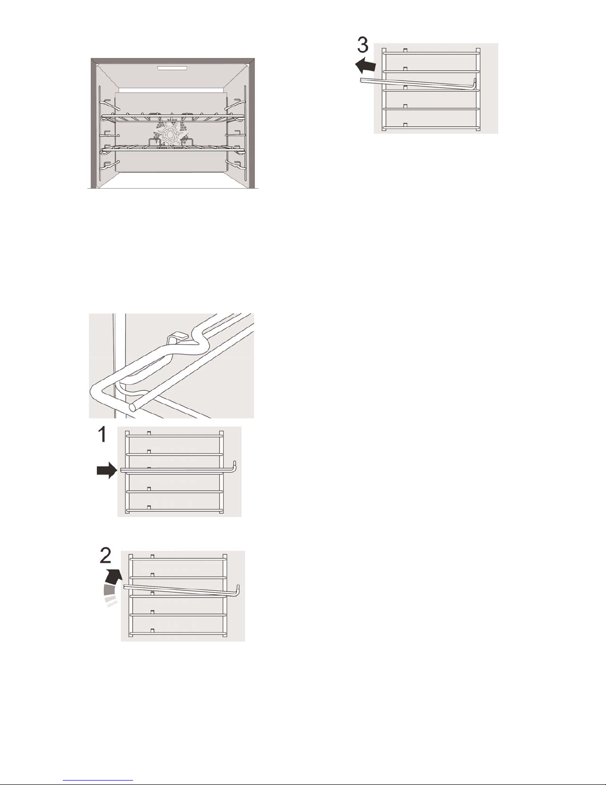
The Fan Oven shelves
The shelves should not be fitted directly one above the
other. When cooking on more than one shelf always leave
at least one runner space between them.
The oven shelves are retained when pulled forward but
can easily be removed and re-fitted.
To remove a shelf first make sure that it is pushed fully
back, so that the shelf stop is in line with the kink in the
side of the shelf.
Lift up the front of the shelf so the shelf will pass over the
shelf stop.
Pull the shelf forward.
To re-fit the shelf, hold it so that it is slightly up at the front
and rest the back of the shelf on the side wires. Push the
shelf to the back of the oven and then lower the front so
that it is resting on the side wires.
Page 20
Essential Information
Before thorough cleaning isolate the electricity supply.
Remember to switch on the electricity supply before use.
Never use paint solvents, washing soda, caustic cleaners,
biological powders, bleach, chlorine based bleach
cleaners, coarse abrasives or salt. Don’t mix different
cleaning products - they may react together with
hazardous results.
Recommended cleaning materials are shown in the table
at the end of this section.
If you want to move your cooker for cleaning, see the
section called ‘Positioning the cooker’.
All parts of the cooker can be cleaned with hot soapy
water - but take care that no surplus water seeps into
the appliance.
For cleaning materials see the ‘Cleaning Table’at the end
of this section.
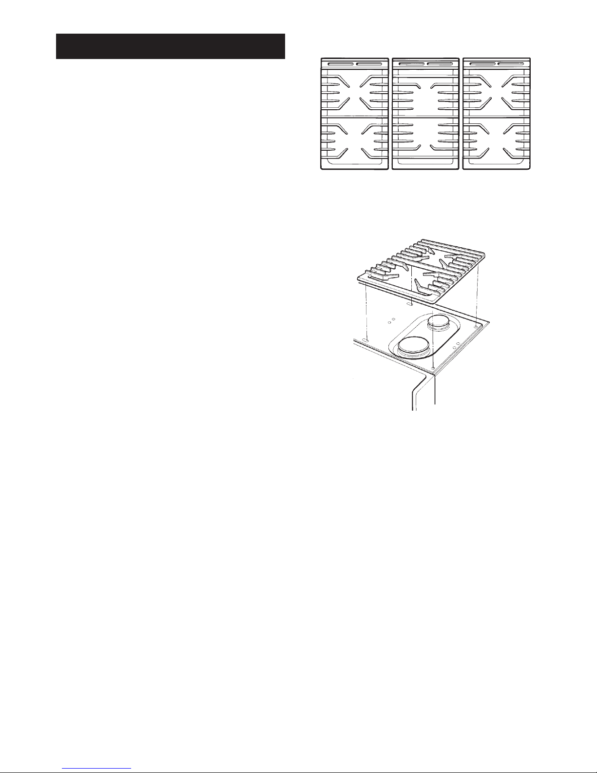
To Remove and Replace Pan Supports
IMPORTANT: The cast iron pan support s on the appliance
are of professional design and much heavier than most if
not all gas hotplate cookers. Therefore care must be taken
when removing or re-fitting them from or to the hotplate. It
is important they are lifted from the appliance. Do not drag
them across adjacent enamelled components as this
could damage the enamel.
The position of each pan support on the hotplate is clearly
marked on the underside and should only be fitted in one
way.
Do not clean pan supports in a dishwasher. See the
‘Cleaning Table’.
NOTE: Aluminium pans may cause a metallic marking on
the pan supports. This will not affect the durability of the
enamel. The appliance warranty does not cover mis-use
of the pan supports.
Cleaning the cooker
20
Page 21
Hotplate burners
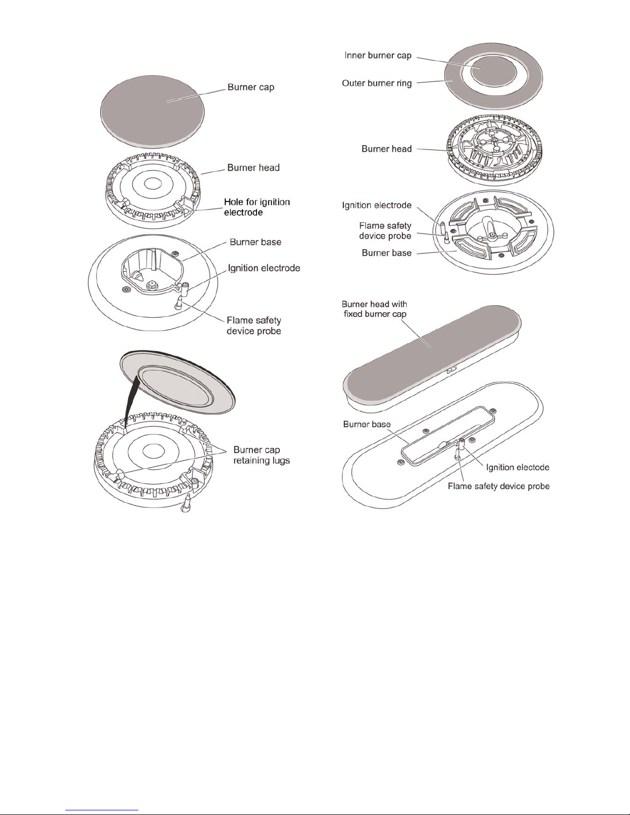
The burner heads and caps can be removed for cleaning.
Make sure they are absolutely dry before replacing.
When fitting the burner head, make sure it locates
properly within the bezel. Take care not to damage the
ignition electrode or the flame safety device probe.
General
Check burner ports are not blocked. If blockage occurs,
remove stubborn particles using a piece of fuse wire.
Stubborn marks on the aluminium burner rings can be
removed using a proprietary cleaner such as Brasso.
21
Wok burner
Fish kettle burner
Page 22
The Slow Cooking Oven and the Grill
The slow cooking oven and the grill have side panels that
are coated with a special enamel that partly cleans itself.
Do not use any cleaning material which may clog the
pores of the special coating e.g. Pastes and powders,
soap filled pads, wire wool, spray cleaners, brush-on oven
cleaners, caustic solutions, metal scrapers/knives, and
prevent the continuous cleaning action.
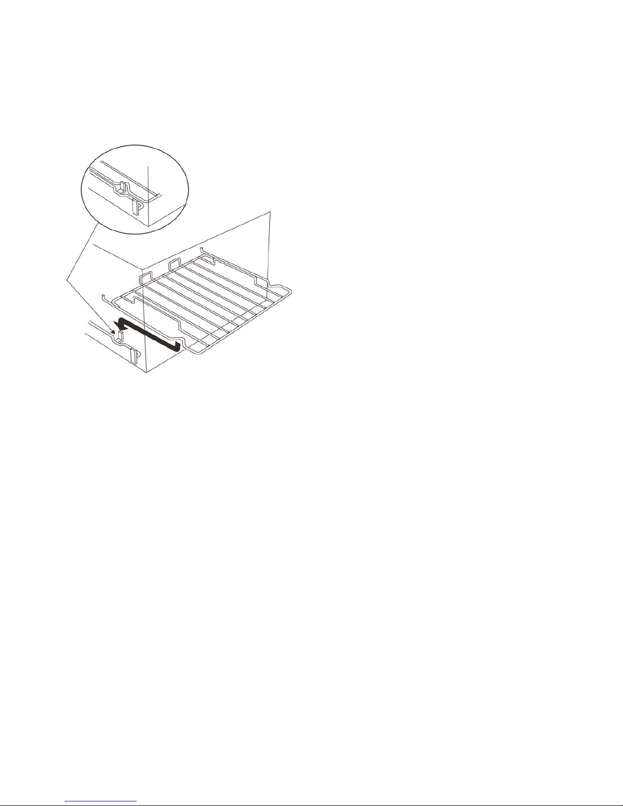
The shelf is designed to lock in place, but is removable for
cleaning. To remove lift up at the front then pull forward.
The grill pan and grid should be washed in hot soapy
water.
After grilling meat or any food that soils, leave the grill pan
to soak for a few minutes in the sink immediately after use.
Stubborn particles may be removed from the grid by using
a nylon brush.
Control Panel and Oven Doors
For best results liquid detergents should be used.
The control panel and control knobs should only be
cleaned with a soft cloth wrung out in clean hot soapy
water - but take care that no surplus water seeps into the
appliance. Wipe with a clean dampened cloth then polish
with a dry cloth. The oven doors should only be cleaned
with a soft cloth wrung out in clean hot soapy water.
The Fan Ovens
The ovens have panels which have been coated with a
special enamel that partly cleans itself. This does not stop
all marks on the lining, but helps to reduce the amount of
manual cleaning needed.
The panels work best if a pattern of low and high
temperature cooking is followed. Occasionally wipe with a
lint free cloth and hot soapy water. When the panels are
dry, heat the ovens to 200ºC for about one hour. This will
ensure the panels are working effectively.
Do not use steel wool (Brillo) or any other materials that
will scratch the surface. Do not use oven cleaning pads.
22
Page 23
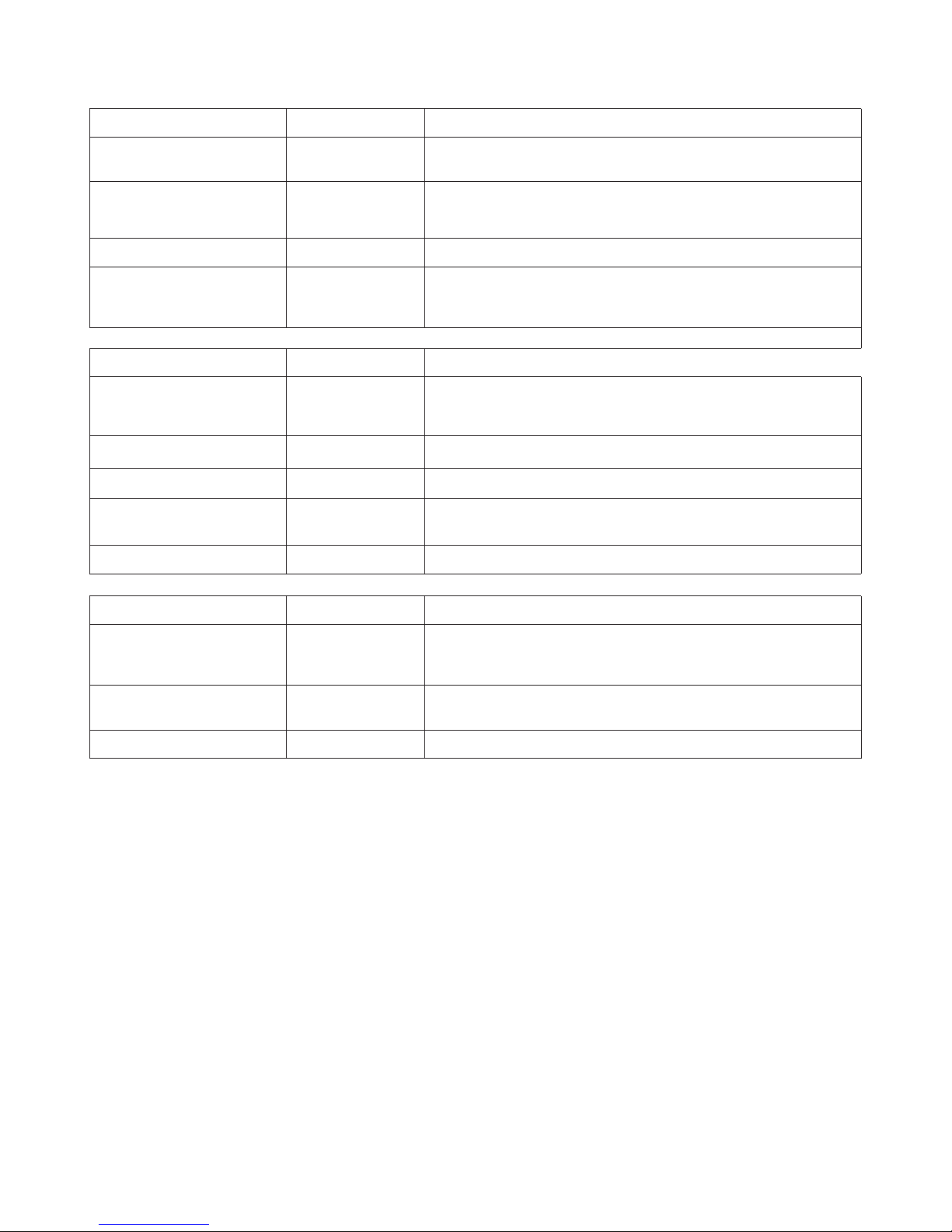
Cleaning Table
Hotplate
23
Part
Hotplate top
Pan supports, wok cradle
(some models only)
Burner caps
Finish
Enamel
Enamel coated
cast iron
Enamel
Recommended Cleaning Material
Hot soapy water, soft cloth. Any stubborn stains remove gently with
a nylon scourer.
Cream cleaner and a nylon scourer or
Well soaped Brillo pad
Cream Cleaner, nylon scourer, dishwasher
Burner trim rings (some
models only) and burner
head
Aluminium
Cream cleaner with a soft cloth. Be careful not to be over vigorous
Outside of cooker
Part
Door, door surround
Door front frame
Sides
Rear grille, plinth
Control panel
Control knobs/handles
Finish
Enamel or paint
Painted surface
Enamel
Enamel
Plastic/chrome
Recommended Cleaning Material
Hot soapy water, soft cloth.
Any stubborn stains, remove gently with a liquid detergent.
Hot soapy water, soft cloth
Hot soapy water, soft cloth. Cream cleaner, with care if necessary.
Warm soapy water. Do not use abrasive cleaners on lettering.
Warm soapy water, soft cloth.
‘Cook & Clean’ oven panels
Special enamel
that partly cleans
itself
This surface cleans itself at 200ºC and above, or the panels can be
washed with hot soapy water and a nylon brush. (See ‘The Ovens’
in ‘Cleaning your cooker’).
Oven shelves, grill trivet Chrome
An oven interior cleaner that is suitable for chrome. Soap filled pad.
Dishwasher.
Grill pan/meat tin Enamel Hot soapy water. Soap filled pad (Brillo). Dishwasher.
Oven and Grill
Part Finish Recommended Cleaning Material
Cleaners listed are available from supermarkets or electrical retailers as stated. Cleaner manufacturer in Italics.
For enamelled surfaces use a cleaner that is approved for use on vitreous enamel. The Vitreous Enamel Association has
a list of approved cleaners. Contact them via their website www.ive.org.uk or telephone 01527 893031.
Regular cleaning is recommended. For easier cleaning, wipe up any spillages immediately.
To help keep your oven clean, cover meat when roasting, with foil or use a roasting bag. Brush vegetables with fat
before placing around the meat.
Page 24

Steam is coming from the oven
When cooking foods with a high water content (e.g. oven
chips) there may be some steam visible at the rear grille.
Take care when opening the oven door, as there may be
a momentary puff of steam when the oven door is opened.
Stand well back and allow any steam to disperse.
The oven fan is noisy
The note of the oven fan may change as the oven heats
up - this is perfectly normal.
The knobs get hot when I use the oven or the grill, can
I avoid this?
Y es, this is caused by heat rising from the oven or the grill,
and heating them up. Do not leave the oven door open.
Make sure that the grill is pushed right back to the
‘backstop’ when grilling.
If there is an installation problem and I don’t get my
original installer to come back to fix it who pays?
Y ou do. Service organisations will charge for their calls out
if they are correcting work carried out by the original
installer. It is advisable to track down the original installer.
Current Operated Earth Leakage Breakers
Where the cooker installation is protected by a 30milliamp sensitivity residual current device (RCD), the
combined use of your cooker and other domestic
appliances may occasionally cause nuisance tripping. In
these instances the cooker circuit may need to be
protected by fitting 100mA device. This work should be
carried out by a qualified electrician.
Food is cooking too slowly, too quickly, or burning
Cooking times may differ from your previous oven.
Individual tastes may require the temperature to be
altered either way , to get the results you want. Try cooking
at different temperature setting.
The fan ovens are not cooking evenly
Do not use a tin or tray larger than 300mm x 240mm (12”
x 9 1/2”).
If you are cooking a large item, be prepared to turn it
round during cooking.
If two shelves are used, check that space has been left for
the heat to circulate. When a baking tray is put into the
oven, make sure it is placed centrally on the shelf.
Check that the door seal is not damaged and that the door
catch is adjusted so that the door is held firmly against the
seal.
A dish of water when placed on the shelf should be the
same depth all over. (For example, if it is deeper at the
back, then the back of the cooker should be raised up or
the front lowered). If the cooker is not level arrange for
your supplier to level it for you.
Oven temperature getting hotter as the cooker gets
older
If turning the knob down has not worked or only worked for
a short time then the cooker may need a new thermostat.
This should be fitted by a service person.
Grill not cooking properly
Are you using the pan and trivet supplied with the cooker?
Is the pan being used on the grill carriage, not the floor of
the compartment? Is the grill tray fully back to the stop?
Hotplate ignition or hotplate burners faulty
Is the power on?
Are the sparker (ignition electrode) or burner slots blocked
by debris?
Are the burner caps correctly located?
Hotplate burners will not light
If only one or all the hotplate burners will not light, make
sure that the parts have been replaced correctly after
wiping or removing for cleaning.
Check that there is not a problem with the gas supply . This
can be done by making sure that other gas appliances are
working.
Do the burners spark when the control knob is pushed in?
If not, check the power is on.
Troubleshooting
24
Page 25
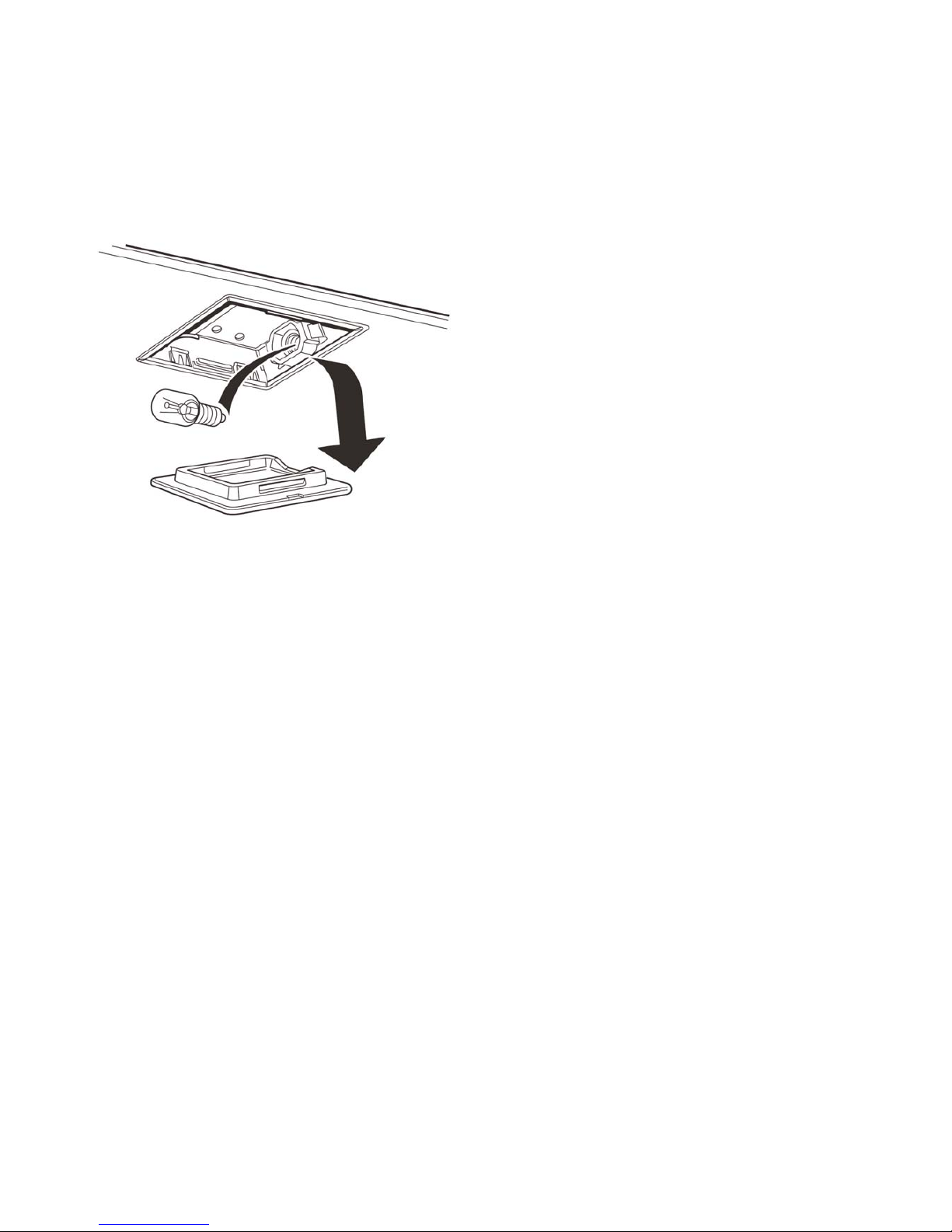
The oven light is not working
The bulb has probably blown. A replacement bulb (which
is not covered under the guarantee) can be purchased
from a good electrical shop. Ask for a 25W, 230V, 300ºC,
FOR OVENS. It must be a special bulb, heat resistant to
300ºC.
Open the oven door and remove the oven shelves.
Turn off the power supply.
Unclip the lamp lens and unscrew the light bulb. Fit the
new light bulb and re-fit lens.
Turn on the electricity supply and check that the bulb now
lights.
Power Failure
In the event of a power failure in the electrical supply the
hotplate may be lit using a match.
If there is an installation problem and I don’t get my
original installer to come back to fix it who pays?
Y ou do. Service organisations will charge for their calls out
if they are correcting work carried out by the original
installer. It is advisable to track down the original installer.
What cleaning materials are recommended for the
cooker?
See the ‘Cleaning the cooker’ section for recommended
cleaning materials. We do not recommend Mr. Muscle, as
it contains chemicals that may damage the surfaces of
your cooker.
25
Page 26

In the Republic of Ireland , the installation must be carried
out by a Competent Person.
The installation must be in accordance with the installation
instructions and comply with the relevant regulations and
also, the local gas and electricity supply companies
requirements.
If you smell gas
Do not turn electric switches on or off.
Do not smoke.
Do not use naked flames.
Do turn off the gas at the meter or cylinder.
Do open door and windows to get rid of the gas.
Call your gas supplier.
The appliance is designed for domestic cooking only. Use
for any other purpose could invalidate any warranty or
liability claim.
The use of a gas cooking appliance results in the
production of heat and moisture in the room in which it is
used. Ensure that the kitchen is well ventilated: keep
natural ventilation holes open or install a mechanical
ventilation device, (mechanical extractor hood).
Prolonged intensive use may call for additional ventilation,
for example opening a window. Use extractor fans or
hoods when fitted.
The cooker should be serviced by a qualified service
engineer and only approved spare parts used. Have the
installer show you the location of the cooker control
switch. Mark it for easy reference. Always allow the cooker
to cool and then switch off at the mains before cleaning or
carrying out any maintenance work, unless specified
otherwise in this guide.
All parts of the cooker become hot with use and will retain
heat even after cooking has finished.
Take care when touching the cooker, to minimise the
possibility of burns always be certain that the controls are
in the OFF position and that it is cool before attempting to
clean the cooker.
Use dry oven gloves where applicable - using damp
gloves will result in steam burns when you touch a hot
surface. Never operate this cooker with wet hands.
Do not use a towel or other bulky cloth in place of a glove.
They might catch fire if they touch a hot surface.
Clean with caution. If a wet sponge or cloth is used to wipe
up spills on a hot surface, be careful to avoid steam burns.
Some cleansers can produce noxious fumes, if applied to
a hot surface.
Do not use unstable saucepans and position the handles
away from the edge of the hotplate.
Babies, toddlers and young children should not be
allowed near the cooker at any time. They should never
be allowed to sit or stand on any part of the appliance.
Teach them not to play with controls or any other part of
the cooker.
Never store anything of interest to children in cabinets
above a cooker - children climbing on the cooker to reach
them could be seriously injured.
Clean only parts listed in this guide.
In the interests of hygenie and safety the cooker should be
kept clean at all times as a build up in fats and other food
stuffs could result in a fire.
Always keep combustible wall coverings or curtains etc. a
safe distance away from your cooker.
Do not spray aerosols in the vicinity of the cooker while it
is on.
Do not store or use combustible materials, or flammable
liquids in the vincinty of this appliance.
Do not use water on grease fires. Never pick up a flaming
dish. Turn the controls off. Smother a flaming pan on a
surface unit by covering the pan completely with a well
fitting lid or baking tray. If available use a multi-purpose
dry chemical or foam type fire extinguisher.
Never leave the hotplate unattended at high heat settings.
Pans boiling over can cause smoking and greasy spills
and may catch fire.
26
General Safety Instructions
Page 27

27
Never wear loose-fitting or hanging clothes while using
the appliance. Be careful when reaching for items stored
in cabinets over the hotplate. Flammable material could
be ignited if brought in contact with a hot surface unit and
may cause severe burns.
Take great care when heating fats and oils, as they will
ignite if they get too hot.
Use a deep fat thermometer whenever possible to prevent
overheating fat beyond the smoking point.
Never leave a chip pan unattended. Always heat fat
slowly, and watch as it heats up. Deep fry pans should be
only one third full of fat. Filling the pan too full of fat can
cause a spill-over when food is added. If a combination of
oil or fats are used in frying, stir them together before
heating, or as the fats melt.
Foods for frying should be as dry as possible. Frost on
frozen foods or moisture on fresh foods can cause hot fat
to bubble up and over the sides of the pan. Carefully
watch for spills or overheating of foods when frying at high
or medium high temperatures. Never try to move a pan of
hot fat, especially a deep fat fryer. W ait until the fat is cool.
When the grill is on, do not use the top of the flue (the slot
along the back of the cooker) for warming plates, dishes,
drying tea towels or softening butter.
When using an electrical appliance near the hotplate, be
sure that the cord of the appliance does not come into
contact with the hotplate.
Take care that no water seeps into the appliance.
Only certain types of glass, glass-ceramic, earthenware or
other glazed containers are suitable for hotplate cooking;
others may break because of the sudden change in
temperature.
Do not allow anyone to climb, stand or hang on any part
of the cooker.
Do not use aluminium foil to cover shelves, linings or the
oven roof.
Never heat unopened food containers. Pressure build-up
may make the container to burst and cause injury.
The cooker is designed for cooking foods only and must
not be used for any other purpose.
The oven should NOT be used for heating the kitchen.
This wastes fuel and the control knobs may become
overheated.
When the oven is on DO NOT leave the oven door open
for longer than necessary.
The specification of this cooker should not be altered.
This appliance is heavy, take care when moving it.
When the cooker is not in use, ensure that the control
knobs are in the OFF position.
Page 28

You must be aware of the following safety
requirements and regulations.
Prior to installation, ensure that the local distribution
conditions (nature of gas and gas pressure) and the
adjustment of the appliance are compatible. See the
appliance data badge.
This appliance shall be installed in accordance with the
regulations in force and only in a well ventilated space.
Read the instructions before installing or using this
appliance.
In the Republic of Ireland, the installation must
be carried out by a Competent Person and installed in
accordance with the current edition of I.S. 813
“Domestic Gas Installations”, the current Building
Regulations and reference should be made to the
current ETCI rules for electrical installation.
Provision of Ventilation
This appliance is not connected to a combustion
products evacuation device. Particular attention shall
be given to the relevant requirements regarding
ventilation.
In the Republic of Ireland
Reference should be made to the current edition of IS
813 which makes clear the conditions that must be met
to demonstrate that sufficient ventilation is available.
Location of Cooker
The cooker may be installed in a kitchen/kitchen diner
but NOT in a room containing a bath or shower.
NOTE:
An appliance for use on LPG shall not be installed
in a room or internal space below ground level. e.g.
in a basement.
28
Installation
All models are supplied set for use on either group H natural gas or for use on LP gas.
See the appliance data badge.
This appliance is designed for domestic cooking only. Use for any other purpose could invalidate any warranty
or liability claim.
Page 29
Dear Installer
Before you start your installation, please complete the details BELOW.
If your customer has a problem relating to your installation they will be able to contact
you easily.
Thank you
Installer's Name
Installer's Company
Installer's Telephone number
29
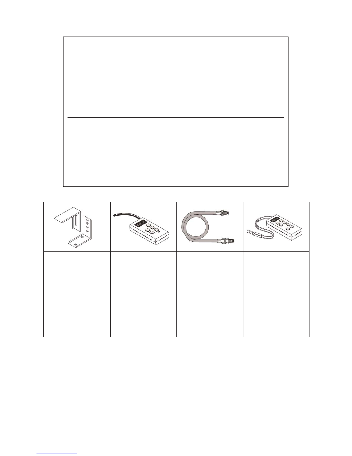
You will only need the following equipment to complete the cooker installation satisfactorily.
STABILITY BRACKET
If the cooker is to be
supplied with gas through
a flexible hose, a stability
bracket or chain must be
fitted.
These are supplied not
with the cooker but are
available at most builders
merchants.
GAS PRESSURE
TESTER
It is important the gas
pressure is set correctly.
FLEXIBLE GAS HOSE
Must be in accordance
with the relevant
standards. For LP Gas it
should be suitable for
LPG, capable of 50 mbar
pressure, 70ºC
temperature rise and carry
a red stripe, band or label.
A hose is not supplied
with the cooker.
MULTIMETER
(for electrical checks)
Make sure the installation
is electrically safe.
You will also need the following tools:
1. Electric drill 5. Flat head screwdriver
2. Masonry drill bit & rawlplugs 6. Spirit level
(only required if fitting the 7. Pencil
cooker on a stone or concrete 8. Adjustable spanner
floor) 9. Screws for fitting stability bracket
3. Steel tape measure
4. Cross head screwdriver
Page 30
Positioning the Cooker
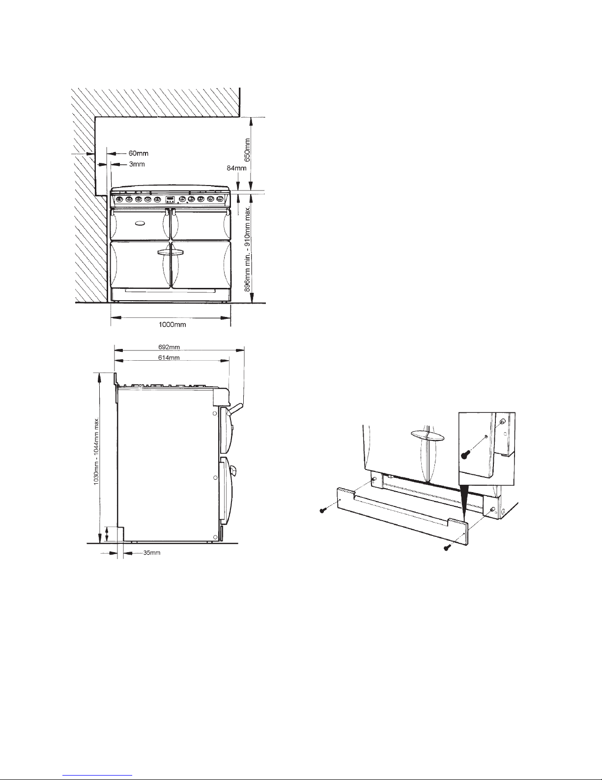
The diagrams show the minimum recommended distance
from the cooker to nearby surfaces.
The hotplate surround should be level with, or above, any
adjacent work surface. Above hotplate level a gap of
60mm should be left between each side of the cooker and
any adjacent vertical surface.
For non-combustible surfaces (such as unpainted metal
or ceramic tiles) this can be reduced to 25mm.
A minimum space of 650mm is required between the top
of the hotplate and a horizontal combustible surface.
Any cooker hood should be installed in accordance with
the hood manufacturers instructions.
Surfaces of furniture and walls at the sides and rear of the
appliance should be heat, splash and steam resistant.
Certain types of vinyl or laminate kitchen furniture are
particularly prone to heat damage and discolouration. We
cannot accept responsibility for damage caused by normal
use of the cooker to any material that de-laminates or
discolours at temperatures less than 65°C above room
temperature.
For safety reasons curtains must not be fitted immediately
behind the cooker.
We recommend a gap of 1006mm between units to allow
for moving the cooker. Do not box the cooker in, it must be
possible to move the cooker in and out for cleaning and
servicing. The cooker should not be placed on a base.
Unpacking the Cooker
Do not take any packaging off the cooker until it is directly
in front of the place it is to be installed (unless it will not fit
through a door in its outer packaging).
Levelling
The Masterchef is designed to stand on a flat and level
surface; however any unevenness maybe overcome by
adjusting the four mobility wheels, one at each corner of
the base plate. The adjusting screws are accessed by
removing the plinth (two screws).
30
Page 31
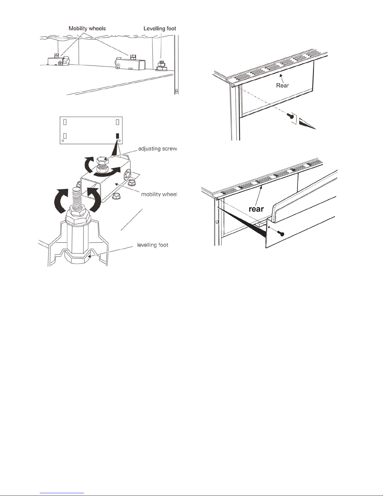
To raise the cooker turn screw clockwise, to lower turn
screw anti-clockwise.
When the cooker is level and in the correct position, the
two feet at the front corners of the cooker MUST be
lowered to come into contact with the floor and support the
cooker (tighten the locknuts). The two front mobility
wheels must then be raised by at least one turn (anticlockwise of the adjusting screw) to ensure that the
cooker is locked in place and cannot accidentally roll out
of position.
Fitting the splashback (optional)
To fit the splashback, the appliance must be moved out
slightly to gain access to the rear of the appliance.
Remove 2 screws as shown.
Fit new splashback as shown.
31
Page 32
Gas Connection
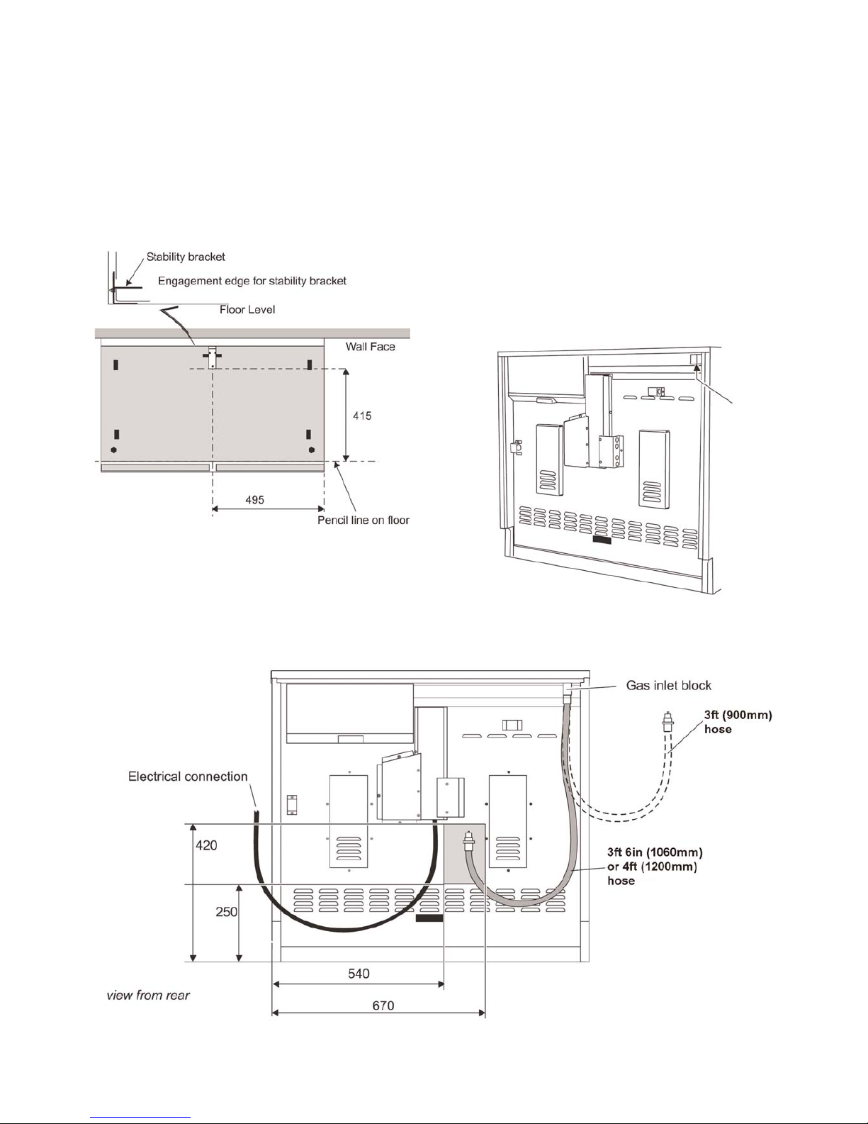
Fitting a stability bracket
A stability bracket or chain (not supplied with the cooker)
should be fitted when the cooker is connected to a flexible
gas supply. Any restraining device should be secured to
the fabric of the building and should be able to be released
so that the cooker can be pulled out for cleaning and
maintenance.
When fitting a stability bracket read these instructions
together with the leaflet supplied with the bracket.
a. Position and level the appliance.
b. Draw a pencil line along the front edge of the base of
the cooker and along the right hand edge.
c. Remove the range.
d. Mark off 495mm from the RH side of the unit to indicate
the centre line for the bracket.
e. Mark off 415mm to locate the front edge of the lower
bracket. Fix bracket to floor.
f. Measure the height from floor level to the bottom of the
opening in the cooker back. Add 3mm to this
dimension and assemble the stability bracket to this
height (i.e. from floor level to underside of top
member).
Gas Connection
The gas supply need to terminate with a down facing
bayonet. The rear cover boxes limit the position of the
supply point.
32
Page 33
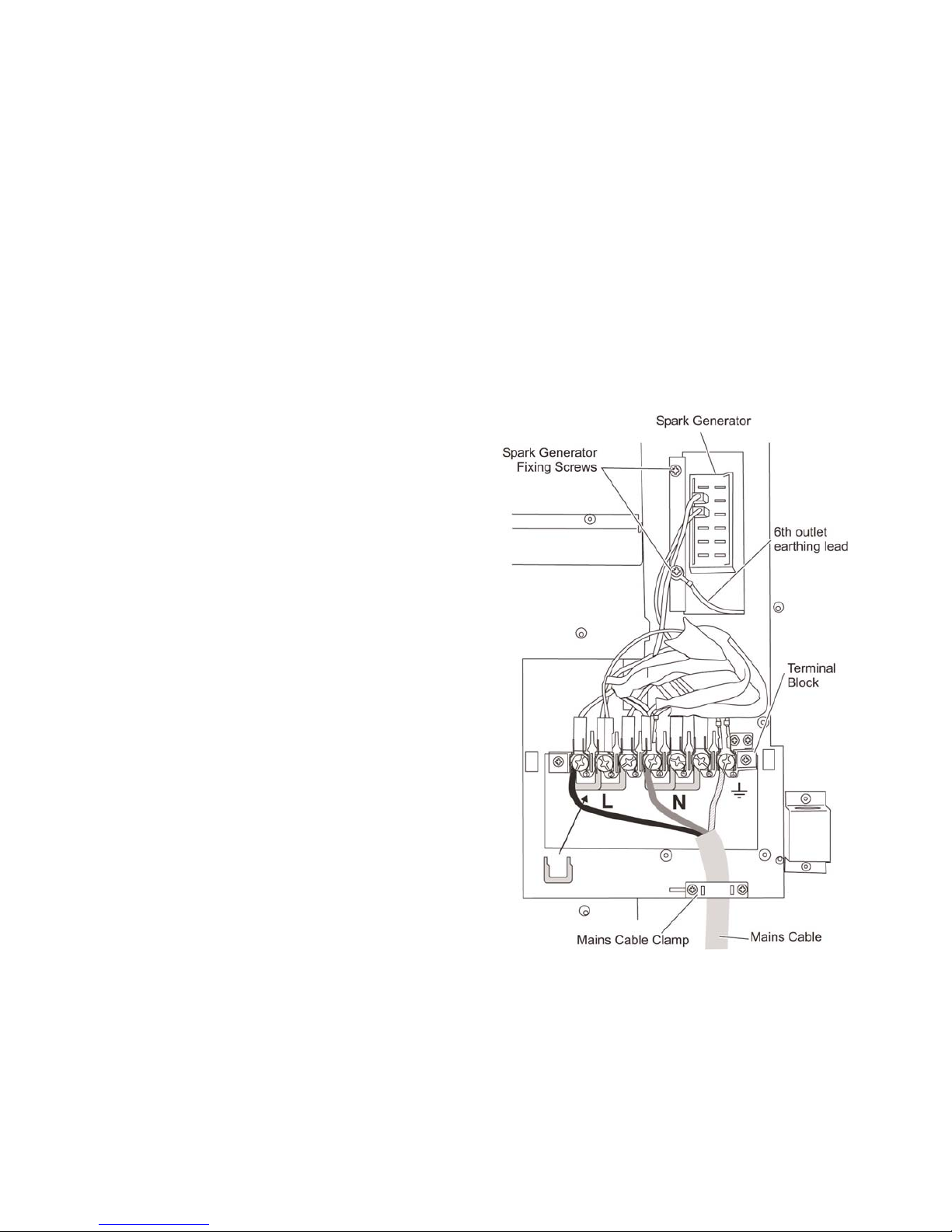
Because the height of the cooker can be adjusted and
each connection is different it is difficult to give precise
dimensions. Ideally the house supply bayonet should be
in the shaded area shown in the diagram. This hose
should be fitted so that both inlet and outlet connections
are vertical so that the hose hangs downwards in a ‘U’
shape. A3ft (900mm) hose will need to be connected from
the side.
For Natural Gas the flexible hose must be in accordance
with B.S. 689.
For LP Gas it should be capable of 50mbar pressure,
70ºC temperature rise and carry a red stripe, band or
label.
If in doubt contact, your supplier.
Screw connect the threaded end of the hose into the gas
inlet in the underside of the connector block on the back
of the cooker.
After completing the gas connection, check the cooker is
gas sound with a pressure test. When checking for gas
leaks do not use washing up liquid - this can corrode. Use
a product specifically manufactured for leak detection.
Pressure Testing
The gas pressure can be measured at the fish kettle
burner jet. Make sure that the cooker is not connected to
the electricity supply. Lift off the burner head. Fit the
pressure gauge to the jet. Turn on one of the other burners
and light it with a match. Turn on the control for the fish
kettle burner and press in the knob to allow the gas
through and register the pressure on the gauge.
For Natural gas cookers the pressure should be 20mbar.
For LP gas (propane) the pressure should be 37mbar.
Re-assemble burner top, making sure it is re-assembled
in the correct way on the burner body.
Electrical Connection
This appliance must be installed by a qualified electrician
to comply with the relevant regulations and also the local
electricity supply company requirements.
WARNING: THIS APPLIANCE MUST BE EARTHED.
NOTE: The cooker must be connected to the correct
electrical supply as stated on the voltage label on the
cooker, through a suitable cooker control unit
incorporating a double pole switch having a contact
separation of at least 3mm in all poles. This cooker must
not be connected to an ordinary domestic power point.
The total electrical load of the appliance is approximately
8.8 kW. The cable size used should be suitable for this
load and comply with all local requirements.
Access to the mains terminal is gained by removing the
electrical terminal cover box on the back panel.
Connect the mains cable to the correct terminals for your
electrical supply type.
33
Page 34
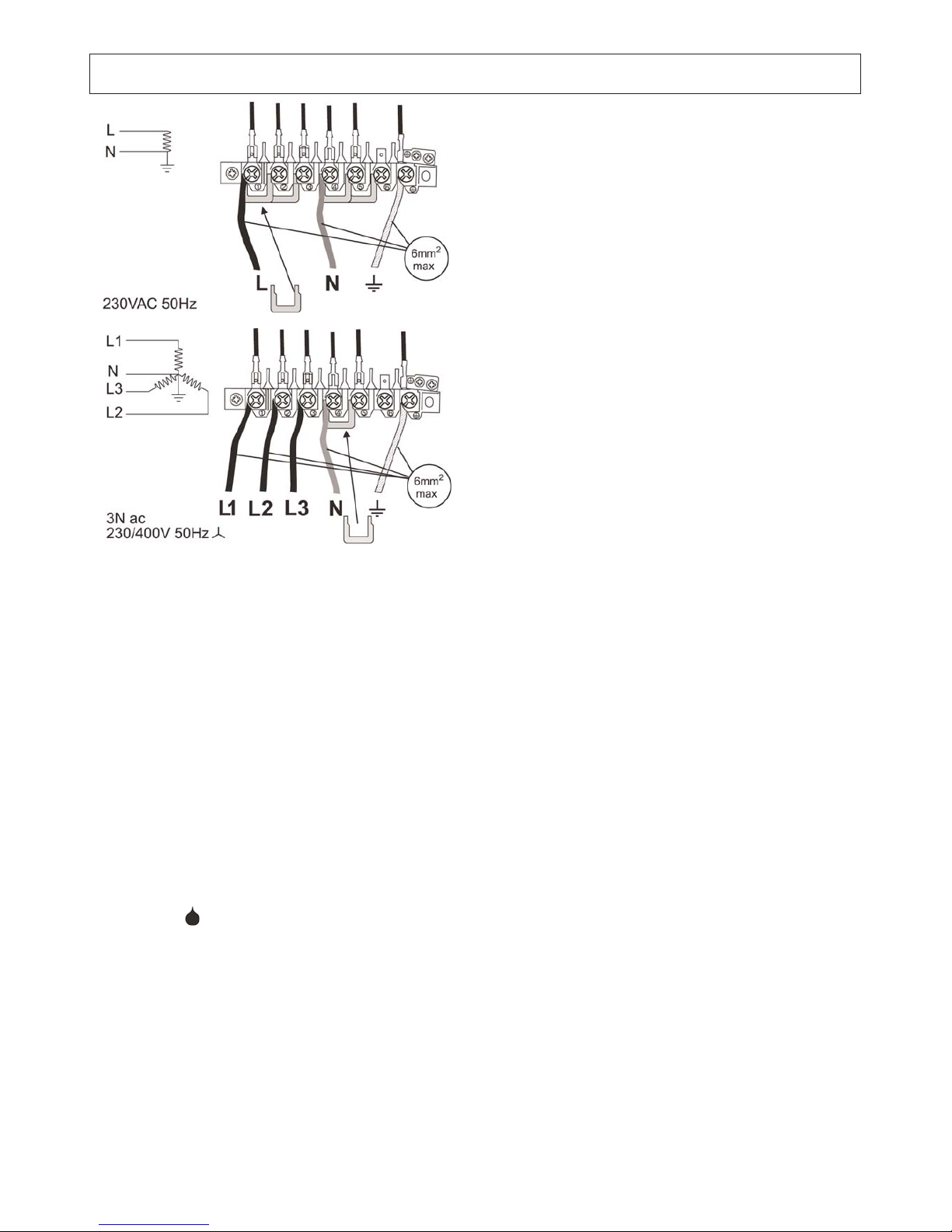
Check that the links are correctly fitted and that the
terminal screws are tight. Secure the mains cable using
the cable clamp.
Current Operated Earth Leakage Breakers
Where the installation is protected by a 30-milliamp
sensitivity residual current device (RCD), the combined
use of your cooker and other domestic appliances may
occasionally cause nuisance tripping. In these instances
the cooker circuit may need to be protected by fitting a
100mA device. This work should be carried out by a
qualified electrician.
Hotplate
Check each burner in turn. There is a flame safety device
that stops the flow of gas to the burner if the flame goes
out. There is also a spark ignition system that works when
the knob is pressed in.
For each burner, push in and turn the knob to the large
flame symbol ( ).
The igniter should spark and light the gas. Keep holding
the knob pressed in to let the gas through to the burner for
a few seconds.
If, when you let go of the control knob, the burner goes
out, the safety device has not held in. Turn the control to
the off position and wait one minute, then try again this
time holding in the control knob for slightly longer.
Grill
Open the grill compartment door. Turn on the grill control
and check that the grill heats up.
Oven Check
Turn on the ovens and check that they start to heat up.
Turn off the ovens.
Fitting the plinth
Remove the 2 screws along the front bottom edge of the
cooker. Hold the plinth in place and refit the 2 screws.
Customer care
Please inform the user how to operate the cooker and
hand over these instructions.
Thank you.
34
SERVICING - WARNING
Disconnect from electricity and gas before servicing. Check appliance is safe when you have finished
Single Phase
Three Phase
Page 35
When servicing or replacing gas carrying components
disconnect from the gas supply before commencing
operation.
Check the appliance is gas sound after completion of
service. When checking for gas leaks do not use washing
up liquid - this can corrode. Use a product specifically
manufactured for leak detection.
CAUTION: DO NOT USE A FLAME TO CHECK FOR
GAS LEAKS.
Do not use re-conditioned or un-authorised gas controls.
Disconnect from the electricity supply before commencing
servicing, particularly before removing any of the
following:- control panel, side panels, hotplate tray or any
electrical components or covers.
Before electrical re-connection, check that the appliance
is electrically safe.
NOTE: References to LH and RH oven apply as viewed
from the front.
BEFORE SERVICING ANY GAS CARRYING
COMPONENTS, TURN OFF THE GAS SUPPLY.
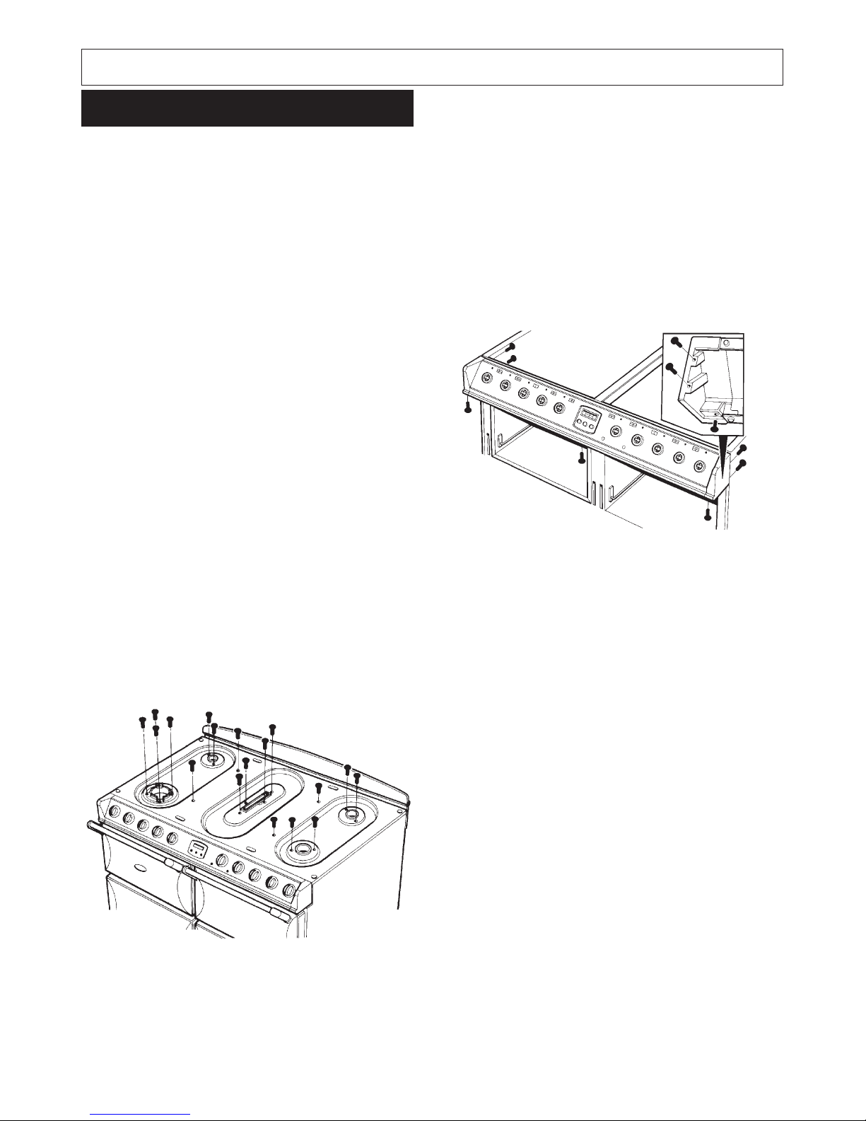
A. To Remove Hotplate
1. Isolate from electric supply.
2. Remove pan supports and burner caps.
3. Remove burner fixing screws (14) and hotplate
fixing screws (4)
4. Lift off hotplate taking care to lift clear of burner
electrodes.
5. Re-assemble in reverse order.
B. To Remove Side Panels
1. Isolate from electric supply.
2. Lower front mobility wheels see section ‘MOBILITY
WHEELS’ in the users instructions.
NOTE: It may be necessary to disconnect the flexible
gas connection to allow the cooker to be withdrawn
from between the kitchen units.
3. Remove fixing screws and lift off side panel.
4. Re-assemble in reverse order.
C. To Remove Facia Castings
1. Isolate from electric supply.
2. Proceed as ‘TO REMOVE HOTPLATE’.
3. Proceed as ‘TO REMOVE SIDE PANELS’.
4. Pull off control knobs.
5. Remove control panel fixing screws (see fig. below).
Support facia when removing screws.
NOTE: When removing facia, the oven indicator neons
and timer require disconnecting from the facia, hold the
cables at their entry into the neon twist and pull, this
will disengage the neon assembly.
D. To Remove Gas Taps/Ignition Switches
1. Isolate from electric supply.
2. Proceed as ‘TO REMOVE HOTPLATE’.
3. Proceed as ‘TO REMOVE SIDE PANEL’.
4. Undo burner gas pipe to tap (15mm nuts).
5. Remove two screws securing tap to gas rail.
6. Withdraw gas tap from gas rail taking care not to strain
ignition switch cables.
7. Disconnect ignition switch cables and slide off switch
activating collar from spindle to tap.
8. Re-assemble in reverse order.
7
E. To Remove Grill Regulator/Light Switch
1. Isolate from electric supply.
2. Proceed as ‘TO REMOVE FACIA CASTINGS’.
3. Remove two screws securing control to control
mounting panel.
4. Withdraw control and cables taking care not to strain
the cables.
5. Disconnect cables from the control.
NOTE: Take care to identify terminations
6. Re-assemble in reverse order.
35
SERVICING - WARNING
Disconnect from electricity and gas before servicing. Check appliance is safe when you have finished
Servicing
Page 36
F. To Remove Oven Thermostats
1. Isolate from electric supply.
2. Proceed as ‘TO REMOVE GRILL REGULATOR’.
3. Remove (10) back panel screws.
4. Remove thermostat phial and capillary through back of
cooker, note correct capillary route.
5. Re-assemble in reverse order.
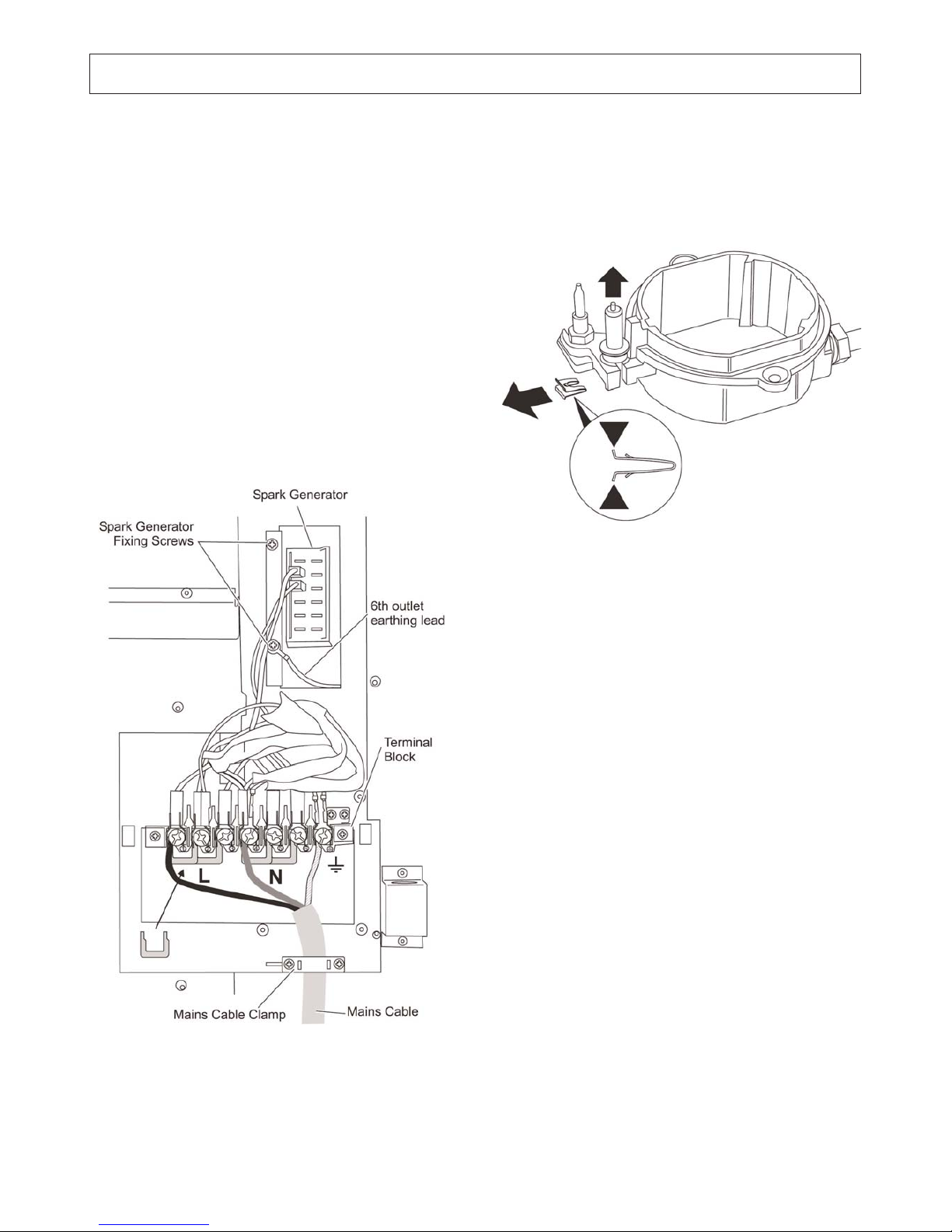
G. To Remove Spark Generator
1. Isolate from electric supply.
2. Lower front mobility wheels (see section ‘MOBILITY
WHEELS’ in Users Instructions) and pull cooker
forwards to gain access to the rear of the cooker.
CAUTION: DO NOT STRAIN FLEXIBLE GAS
CONNECTION disconnect if necessary.
3. Remove mains cable inlet cover, 8 screws.
4. Disconnect electric cables to generator.
5. Remove two screws securing generator mounting
bracket to cooker frame and carefully withdraw
generator sufficiently to disconnect electrode leads.
6. Re-assemble in reverse order.
H. To Remove Electrode
1. Isolate from electric supply.
2. Proceed as ‘TO REMOVE SPARK GENERATOR’
disconnect the appropriate electrode lead.
3. Proceed as TO REMOVE THE HOTPLATE’.
4. Withdraw clip securing electrode to burner and
withdraw lead and electrode (see fig. below).
5. Re-assemble in reverse order.
I. To Remove Grill Element
1. Isolate from electric supply.
2. Remove two screws securing grill pelmet and remove
pelmet.
3. Remove two screws securing grill element fixing to
carrier to grill cavity and allow element and carrier to
hinge down from the rear.
4. The element can now be lifted out of the carrier to
allow access to the electric terminals at the rear.
5. Disconnect the terminals taking note of their
termination sequence and routing to avoid trapping
cables during re-assembly.
6. Re-assemble in reverse order.
SERVICING - WARNING
Disconnect from electricity and gas before servicing. Check appliance is safe when you have finished
36
Page 37
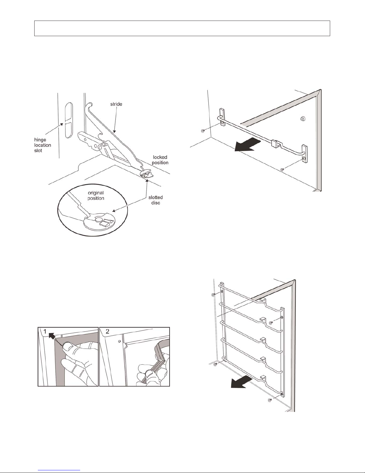
J. To Remove Upper Doors
1. Open door fully.
2. Rotate hinge locking disc 90° clockwise on both door
hinges to lock door in open position.
3. Carefully close door and at approximately half closed
the hinges will release themselves from the cooker
frame.
4. Re-assemble in reverse order.
K. To Remove Oven Door Seal
1. Open oven door. The seal is held in place by small
hooks on the rear face. At the corner pull seal
diagonally away from the door centre until the hook is
released.
2. Proceed to the next hook and release it in a similar
way, and so on. Use force if the hooks are stiff, as the
old seal will be discarded.
3. Hook the new seal in one of the corner holes of the
door and proceed round the door opening snapping
each hook in turn.
L. To Remove Upper Door/Grill Liners
1. Proceed as ‘TO REMOVE DOORS’.
2. Remove door seal (upper oven only) by unhooking
from the front frame at the four corners.
3. Remove LH and RH shelf runners (2 screws per
runner). The liners can now be withdrawn. Also remove
4 top fixing screws.
M. To Remove Lower Oven Liners
1. Open door
2. Remove door seal by unhooking from its four corners.
3. Remove screws securing shelf runners (4 each side).
4. Remove rear liner 4 screws.
5. Remove rear liner mounting brackets 2 screws each
side.
6. Whilst supporting the roof liner remove side linings and
roof liner.
7. Re-assemble in reverse order.
SERVICING - WARNING
Disconnect from electricity and gas before servicing. Check appliance is safe when you have finished
37
Page 38
N. To Remove Upper Oven Elements
1. Isolate from electric supply.
2. Proceed as ‘TO REMOVE UPPER OVEN LINERS’.
3. Lift out oven base to gain access to the oven element.
4. Remove screw securing element to frame.
5. Carefully withdraw element from frame so that the
electric terminals can be disconnected, take care not to
allow the cables to drop down the back of the
appliance.
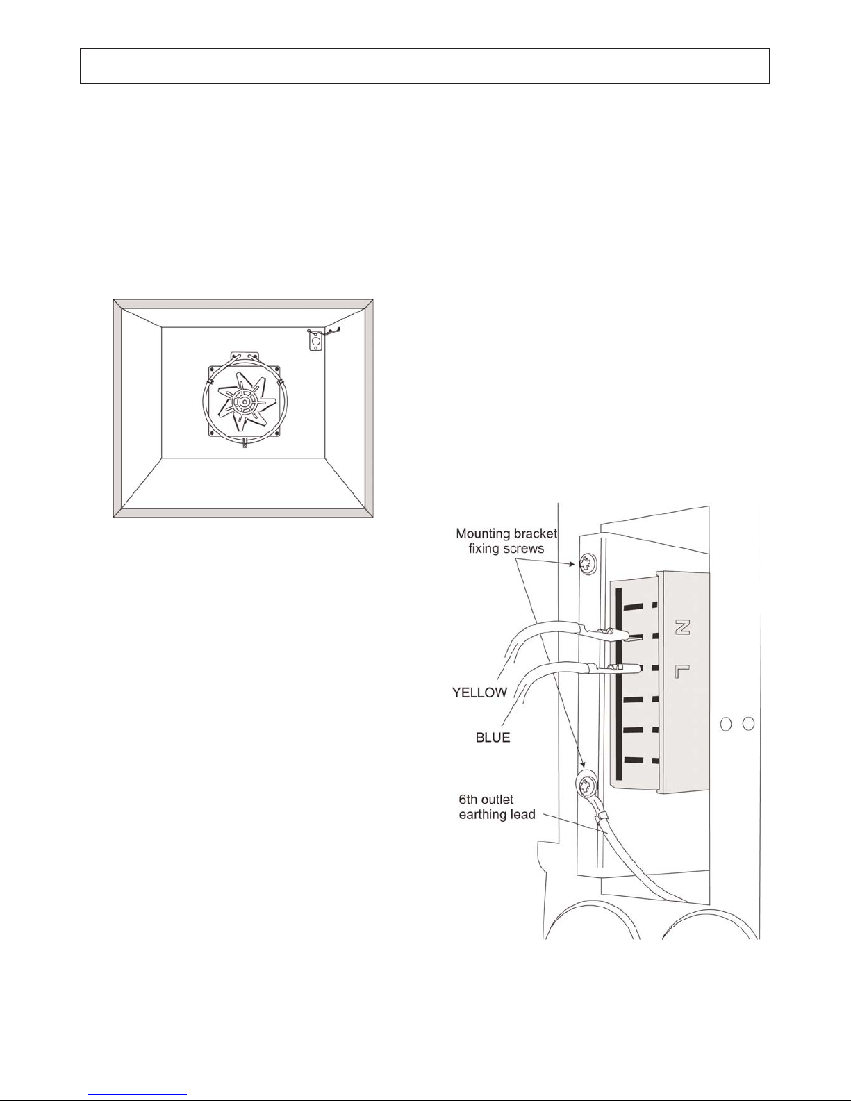
O. To Remove Fan Oven Element
1. Isolate from electric supply.
2. Proceed as ‘TO REMOVE OVEN LINERS’.
3. Remove 3 screws securing element to frame and
carefully withdraw element until access can be made
to the electrical terminals.
4. Disconnect terminals taking care not to allow the cable
to fall down the rear of the appliance.
5. Re-assemble in reverse order.
P. To Remove Oven Fan
1. Isolate from electric supply.
2. Proceed as ‘TO REMOVE OVEN ELEMENT’.
3. Remove 4 fixing screws securing fan assembly to
frame.
4. Withdraw fan assembly sufficiently to gain access to
motor electrical terminals and disconnect cables.
5. Remove fan blade.
NOTE: Fan blade fixing nuts is LH thread.
6. Remove motor from mounting plate screws.
7. Re-assemble in reverse order.
Q. To Remove Door Liners/Door Handles/Door Glass
1. Proceed as ‘TO REMOVE DOORS’.
2. Remove liner fixing screws (4 screws upper oven door,
6 screws lower oven door).
3. Access can now be made to fixing screws of the
hinges, door glass and handle.
4. Re-assemble in reverse order.
R. To Remove Oven Lamp
1. Isolate from electric supply.
2. Process as ‘TO REMOVAL TOP OVEN/GRILL
LINERS’.
3. Remove door seal if necessary by unhooking from the
four corners.
4. Lift out base panel to gain access to lamp electrical
terminals and disconnect cables.
5. Remove lamp lens.
6. The lamp body can now be removed by depressing
four retaining tags on the lamp body.
7. Re-assemble in reverse order.
S. To Remove Spark Generator
1. Isolate from electric supply.
2. Lower front mobility wheels (See Section ‘MOBILITY
WHEELS’ in Users Instructions) and pull cooker
forward to gain access to the rear of the cooker.
CAUTION: DO NOT STRAIN FLEXIBLE GAS
CONNECTION disconnect if necessary.
3. Remove mains cable inlet cover, 8 screws.
4. Disconnect electric cables to generator.
5. Remove two screws securing generator mounting
bracket to cooker frame and carefully withdraw
generator sufficiently to disconnect electrode leads.
6. Re-assemble in reverse order.
SERVICING - WARNING
Disconnect from electricity and gas before servicing. Check appliance is safe when you have finished
38
Page 39

39
SERVICING - WARNING
Disconnect from electricity and gas before servicing. Check appliance is safe when you have finished
Circuit Diagram
A Grill energy regulator
B Outer grill element
C Inner grill element
D Slow cooking oven thermostat
F Slow cooking oven element
G Oven light switches
H1Right hand oven light
H2Left hand oven light
M Left hand oven thermostat
O Left hand oven element
P Left hand oven fan
I Right hand oven thermostat
J Right hand oven fan
K Right hand oven element
Q Clock
R Ignition switches
S Spark generator
T Terminal
U1Right hand oven neon
U2Left hand oven neon
Y Mains terminal
X Cut out
Colour Code
b Blue
bl Black
br Brown
gr Grey
g/y Green/Yellow
or Orange
v Violet
w White
y Yellow
Page 40
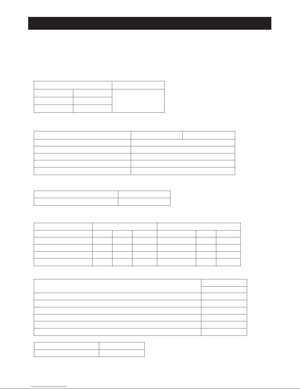
Technical Data
This cooker is either Cat I2H (Nat Gas) or I3+ (LP Gas).
Check the appliance data badge.
INSTALLER: Please leave these instructions with the User.
DATABADGE LOCATION: Behind plinth panel, serial number repeater badge below right hand oven opening.
Country of Destination: GB/IE
(See appliance data badge for test pressures)
Dimensions
Connections
Ratings
Gas burner inputs based on Gross Calorific Value
Maximum total electrical load at 230V 8.5 kW (approximate total including oven lights, etc.)
Gas
Gas
Electric
220 - 240V 50Hz
Rp
1
/2 at rear right-hand side
Hotplate
Left hand front wok
Right hand front Rapide
Rear Semi-Rapide
Centre Fish Burner
Fan Ovens
Energy efficiency class on a scale of A (more efficient) to G (less efficient)
Energy Consumption based on a standard load
Usable Volume (litres)
Size
Time to cook standard load
Grill
Slow cooking oven
Surface area of the grid
Natural Gas
Input
3.5 kW
3.0 kW
1.75 kW
2.6 kW
Injector
130
116
097
108
Injector
95
85
65
80
Bypass
96
54
39
70
Bypass
57
40
32
47
Input
3.5 kW (250g/h)
3.0 kW (214g/h)
1.75 kW (125g/h)
2.6 kW (186g/h)
Forced air convection
2.5 kW
B
1.05 kWh
49
Medium
50 minutes
720cm
2
2.5kW
1.2kW
Propane Gas
Overall height
Overall width
Overall depth including handles
Overall depth excluding handles
Space for fixing
Minimum space above hotplate
minimum 915mm
1000mm See ‘Positioning of Cooker’
660mm
600mm
See ‘Positioning of Cooker’
800mm
maximum 940mm
Natural Gas
Propane
20mbar
220 - 240V 50Hz37mbar
Electric
40
Butane 28 - 30mbar
Page 41

41
Page 42

42
Page 43

43
Page 44

44
For further advice or information contact your
local distributor/stockist
With Waterford Stanley’s policy of continuous
product improvement, the Company reserves the
right to change specifications and make
modifications to the appliance described at any
time.
Supplied by
Waterford Stanley Ltd
Unit 210
IDA Industrial Estate
Cork Road
Waterford
Ireland
Tel: (051) 302300 Fax: (051) 302315
www.waterfordstanley.com
 Loading...