

Page 1
IHSTBUCTION MANUAL
WARNING; FOR SAFE OPERATION
READ INSTRUCTION MANUAL.
IF YOU HAVE ANY QUESTIONS,
CALL US TOLL FREE:
800 762 6672
KEY INFORMATION
YOU SHOULD KNOW
Shaper/Router
POUR LE FRANÇAIS, VOIR LA
COUVERTURE ARRIÈRE.
VEA EL ESPAÑOL EN LA
CONTRAPORTADA.
Always make certain that material is fed
into the cutter rotation whether unit is
operating in forward or reverse.
Remove material from cuts in small
amounts and in multiple passes. This will
preserve both motor and cutter life and
provide the highest quality of cut. Always
use sharp cutters and bits.
Make certain that spindle and router bit
lock nuts are tightened snugly before
each use.
Page 2
WARNING: FOR YOUR OWN SAFETY, READ INSTRUCTION MANUAL BEFORE OPERATING SHAPER. ALWAYS WEAR EYE PROTECTION. DO NOT WEAR GLOVES,
NECKTIES, JEWELRY OR LOOSE CLOTHING. CONTAIN LONG HAIR. DO NOT OPERATE WITHOUT GUARDS IN PLACE. MAKE SURE CUTTER MEETS OR EXCEEDS SPEED
RATING OF TOOL. BE SURE SHAPER CUTTER IS PROPERLY SECURED, WITH KEYED WASHER DIRECTLY UNDER SPINDLE NUT, AND SPINDLE NUT TIGHT. DO NOT USE
AWKWARD HAND POSITIONS. KEEP FINGERS AWAY FROM REVOLVING CUTTER • USE FIXTURES WHEN NECESSARY. FEED WORKPIECE AGAINST ROTATION OF
CUTTER. DO NOT EXPO^ TO RAIN OR USE IN DAMP lOCATlOIS. SECURE TOOL PROPERLY TO PREVENT UNEXPEaED MOVEMENT. DO NOT OPERATE THIS MACHINE
WHILE UNDER THE INFLUENCE OF ALCOHOL OR DRUGS. FAILURE TO COMPLY WITH THESE WARNINGS MAY RESULT IN SERIOUS PERSONAL INJURY.
FORWARD/
RWfRSf SWITCH
OH/OFF SWITCH
WRENCHES
CUTTER DEPTH
HANDLE
ClEAlt FUSTIC GUARD
WODDEN FENCE BOARD
TABLE
MITER GAUGE
STORAGE
FENCE BRACKET
CENTER YOKE
SnOFICATIONS
l20Vohj
864 Worn
60 Hz
9Ami»
Page 3

IMPORTANT SAFETY INSTRUCTIONS
WARNING: When using electric tools, basic safety precautions should
always be followed to reduce risk of fire, electric shock, and personal
injury, including the following:
READ Aa INSTRUCTIONS
Double Insulation
Double insulated tools are constructed throughout with two separate
loyers of electrical insulation or one double thickness of insulation
between you and the tool's electrical system. Tools built with this
insulation system are not intended to be grounded. As a result, your
tool is equipped with a two prong plug which permits you to use
extension cords without concern for maintaining a ground connection.
NOTE: Double insulation does not take the place of normal safety
precautions when operating this tool. The insulation system is for
added protection againsf injury resulting from a possible electrical
insulation failure within the tool.
CAUTION: When servicing use only identical replacement parts.
Repair or replace damaged cords.
Polarized Plugs
Polarized plugs (one blade is wider than the other) are used on
equipment to reduce the risk of electric shock. When provided, this
plug will fit into a polarized outlet only one way. If the plug does not fit
fully in the outlet, reverse the plug. If It still does not fit, contact a
■ qualified electrician to install the proper outlet. Do not change the plug
in any way.
Safety Instructions For All Tools
• KEEP GUARD IN PLACE and in working order.
• REMOVE ADJUSTING KEYS AND WRENCHES. Form habit of
checking to see that keys and adjusting wrenches are removed from
spindle before turning tool on.
• KEEP WORK AREA CLEAN. Cluttered areas and benches
invite accidents.
DON'T USE IN DANGEROUS ENVIRONMENT. Don't use power
tools in damp or wet locations, or expose them to rain. Keep work
area well lignted.
KEEP CHILDREN AWAY. All visitors should be kept at a safe
distance from work area.
MAKE WORKSHOP KID PROOF with padlocks, master switches, or
by removing starter keys.
DON'T FORCE TOOL It will do the job better and be safer at the
rate for which it was designed.
USE RIGHT TOOL Don't force tool or attachment to do a job for
which it was not designed.
WEAR PROPER APPAREL No loose clothing, gloves, neckties, rings,
bracelets, or other jewelry to get caught in moving parts. Nonslip
footwear is recommended. Wear protective hair covering to contain
long hair.
ALWAYS WEAR SAFETY GLASSES. Also use face or dust mask if
cutting operation is dusty. Everyday eyeglasses have only impact
resistant lenses, they are NOT safely glasses.
DON'T OVERREACH. Keep proper footing and balance at all times.
MAINTMN TOOLS WITH CMtE. Keep tools sharp and clean for best
and safest performance. Follow inshbctions for lubricating and
changing accessories.
DISCONNECT TOOLS before servicing; when changing accessories
such as blades, bits, cutters, etc.
REDUCE THE RISK OF UNINTENTIONAL STARTING. Make sure
switch is in OFF position before plugging in. If a power failure
occurs and switch is left on, tool will start immediately when
power is restored.
USE RECOMMENDED ACCESSORIES. The use of improper
accessories may cause risk of injury to persons.
NEVER STAND ON TO^ Serious injury could occur if the tool is
tipped or if the cutting tool is unintentionally contocted.
CHECK DAMAGED PARTS. Before further use of the tool, a guard or
other part that is damaged should be corefully checked to o^rmine
that it will operate properly and perform its intended function—
check for alignment or moving parts, binding of moving parts.
Page 4

breakage of parts, mounting and any other conditions that may
affect its operation. A guard or other part that is damaged should
be properly repaired or replaced. Do not use tool if switch does not
turn it on and off.
• NEVER LEAVE TOOL RUNNING UNATTENDED. TURN POWER OFF.
Don't leave tool until it comes to a complete stop.
• DO NOT OPERATE ElEaRIC TOOLS NEAR FLAMAAABLE UQUIDS
OR IN GASEOUS OR EXPLOSIVE ATMOSPHERES. Motors in these
tools may spark and ignite fumes.
• EXTENSION CORDS. Make sure your extension cord is in good
condition. When using an extension cord, be sure to use one heavy
enough to carry the current your product will draw. An undersizeci
cord will cause a drop in fine voltage resulting in loss of power and
overheating. The table on page 2 snows the correct size to use
depending on cord length and nameplate ampere rating. If in
doubt, use the next heavier gage. The smaller the gage number, the
heavier the cord.
Volh Ibtei Ungth of Cord in Fm)
120V 0-25 26-50 5M00 101*150
240V
Ampere Rah'ng
More Noi more
Thon Than
Ô *
6 * 10 18 16
10 ■ 12 16 16 14 12
12 * 16
Minimum Gog« for Cord Seh
________
0*50 51*100 101*200 201*300
American Wire Goge
6 18 16 U
14 12
\4
14 12
Nol Recommended
• OUTDOOR USE EXTENSION CORDS. When tool is used outdoors,
use only extension cords intended for use outdoors and so marked.
• STAY ALERT, Watch what you are doing. Use common sense. Do
not operate tool when you are tired.
Additional Safety Rules for the Shoper/Router
• KEEP GUARDS in place and in working order.
• WARNING; Do not operate your shaper/router until it is completely
assembled and installed according to the instructions.
• MAKE SURE wiring codes and recommended electrical connections
are followed.
’ NEVER turn the Shaper/Router ON before clearing the table of all
objects (tools, scraps of wood, etc.).
' DO NOT process materials less than 12" (30 cm) in length or 4"
(10 cm) in width without special supporting fixtures.
' ALWAYS use a miter gage when edge shaping work less than
6" (15 cm) wide.
AVOID awkward hand positions where a sudden slip could allow
your hand to contact the cutter.
KEEP hands away from cutting tool.
NEVER run the stock between the fence and the cutter.
DO NOT feed material that is warped, cantains knots or is
embedded with foreign objects, such as nails or staples.
NEVER start the Shaper/Router with the stock in contact with
the cutter.
ALWAYS use auxiliary guard for any operation when the fence has
been removed.
NEVER perform layout, assembly or set-up work on the table while
the shaper is operating.
KEEP cutting tools sharp and free from rust and pitch.
THE WOODEN FENCE BOARDS should be adjusted as close to the
clear plastic guard as possible.
ALWAYS lock fence hardware securely after making
fence adjustments.
MAKE CERTAIN cutting tools are properly secured before
starting machine.
WARNING: For your own safety, read instruction manual before
operating shaper.
a) Be sure keyed washer is directly under spindle nut and spindle
nut is tight.
b) Feed workpiece against rotation of cutter.
c) Use auxiliary guard when adjustable fence is not in place.
DO NOT perform any operation freehand. ALWAYS use fence for
straight shaping; miter gage for end shaping; and starting pin and
cutters with rub collars for curve shaping.
Page 5
• CAUTION: If a power failure occurs and the switch is left ON, the
tool will start immediately when power is restored.
> ALWAYS a collar or bearing guide must be used when cutting if the
fence assembly is removed.
■ ALWAYS use guards provided with the machine.
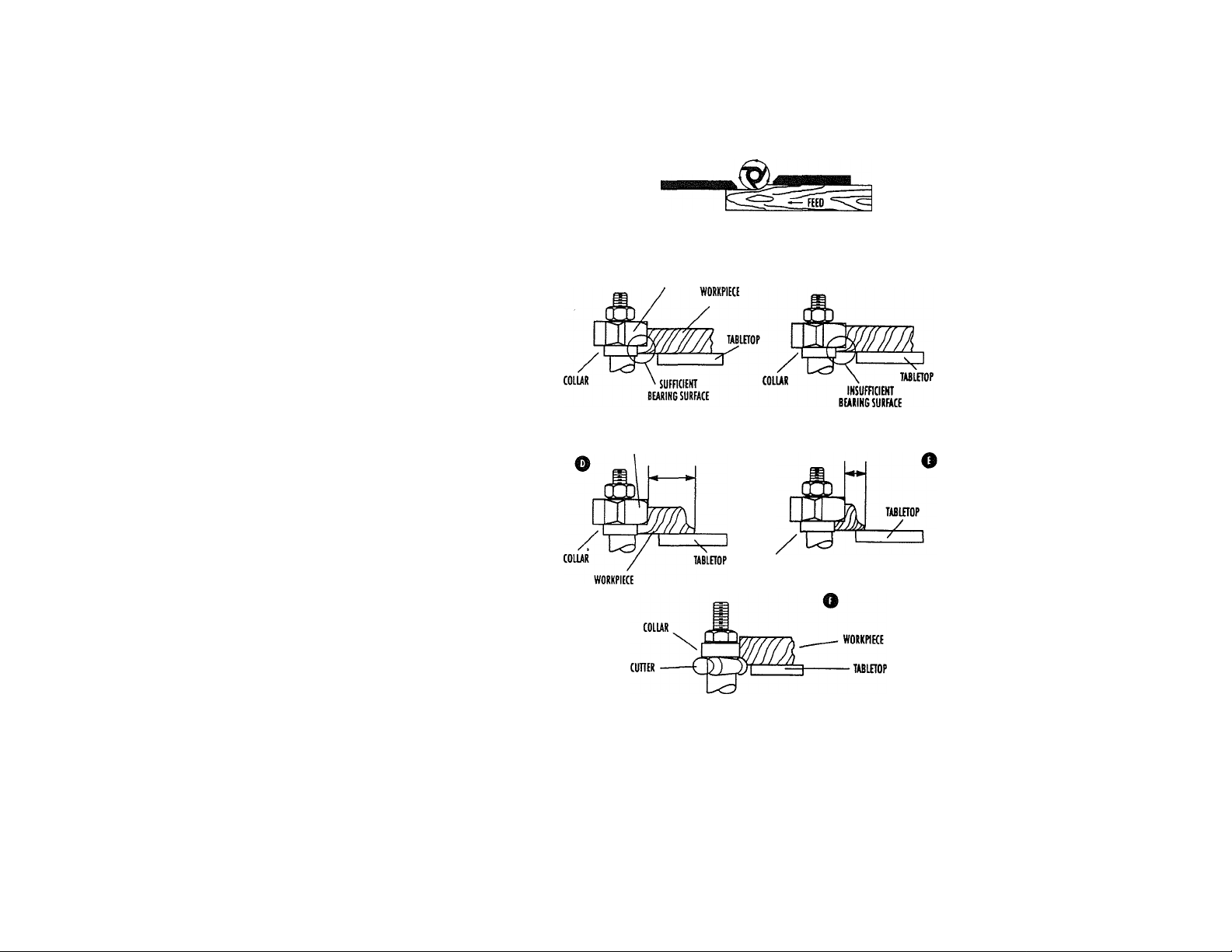
' ALWAYS feed against the cutter rotation, as shown in Figure A.
• WHEN SHAPING with collars and starting pin, the collar MUST
have sufficient bearing surface against the workpiece to prevent
erosion, as shown in Figure B. Figure C, illustrates the wrong way
for this operation as the collar DOES NOT have sufficient
bearing surface.
WHEN SHAPING OR ROUTING with collars and starting pin, the
workpiece must be fairly wide in proportion to the cut being made
as shown in Figure D. UNDER NO CIRCUMSTANCES should short
workpieces of narrow material be shaped against the collars as
shown in Figure E. .
WHEN SHAPING with collars and starting pin, the cutter should be
positioned below the collar whenever possible, <
positioned below the collar whenever possible, os shown i
Figure F.
MAKE all adjustments with the power OFF.
KEEP cutter guards in place and in working order.
WEAR EAR PROTECTION when operating this tool.
YOUR HANDS MUST ALWAYS remain at a safe distance — at least
6" (15 cm) — away from the cutter to avoid making contact with
the cutter should loss of control occur.
USE an auxiliary or scrap piece to push the workpiece and use
auxiliary guides made from other scrap pieces clamped to the table
and/or fence, if necessory, to keep your hands safely away from
the cutter.
USE RECOMMENDED ACCESSORIES. The use of improper
accessories may cause risk of personal injury.
SAVE THESE INSTRUaiONS FOR FUTURE USE
o
CORRE0
CUTTiR
CUTTER CORRECT
CUITEIi
ROTATION
INCORRECT
INCORRECT
Page 6

Parts
a. (1) Auxiliary guard
b. (1) Vacuum adapter
c. (2) Wooden fence boords
d. (2) Wrenches
e. (1) Fence bracket
f. (1) Center Yoke
g. (11 Table Insert
h. (1) Miter gauge
HARDWARE BAG 1
i. (2) 23mm (0.9'
j. (21 ldmm(0.63'
k. (2) 30mm (1.2") knobs
l. (2) 8mm (0.32") Flat washers
m. (5) 6mm (0.24”) Flat washers
n. (4) Hex nuts
o. (4) Flathead screws
HARDWARE BAG 2
p. (1) Starting pin
q. (1) Shaper spindle
r. (1) Collet nut
s. (1) Shaper/spindie nut
t. (1) 1/2" (12.7mm) Collet
u. (1)1 /4" (6.35mm) Collet
V. (1) Cutter nut
w. (1) Keyed wosher
X. (2) 30mm x 6mm (1.2" x 0.24") Collars
y. (1) 32mm x 4mm (1.26" x 0.16") Collar
z. ¡1) 22mm (0.87") Spacer
A. (1) 20mm (0.79") Spacer
I clear guard lock knobs
I knobs
h.
x./y.
q-
t./u.
:./A.
Page 7

Shaper
ASSEMBUNG AND INSTALUNG THE FENCE
A cardbtxird box inside the tool carton contains the larger fence
parts. The hardware required for assembly is in two (2) plastic bags in
the cardboard box.
Select, from the cardboard box, the center yoke, the two wooden
fence boards and the fence bracket shown in Figure 1. Loosely install
the fence bracket, as shown in Figure 2, using one of the 23mm
(0.9") knobs and 6mm flat washers from the plastic bag. Use the four
hothead screws, 6mm washers and hex nuts from the plastic bag to
loosely install the wooden fence boards to the center yoke and the
fence bracket, as shown in Figure 3.
Using two 30mm (1.2") plastic knobs and (2) 8mm (0.32") Rat
washers from the plastic bag, install the fence to the table top, as
shown in Figure 4. Thread these knobs into the two threaded holes
closest to the rear of the-table. (The third threaded hole closer to the
front of the table is for the starting pin which will be discussed later.
Do not install it at this time.)
Use a straightedge to make the two wooden boards even with each
other and hold that position while you firmly tighten the four screws
and the plastic fence bracket knob, as shown in Figure 5. Move the
completed fence as necessary to make it roughly parallel to the rear
edge of the table fop. Securely tighten the two knobs to hold the
fence stationary.
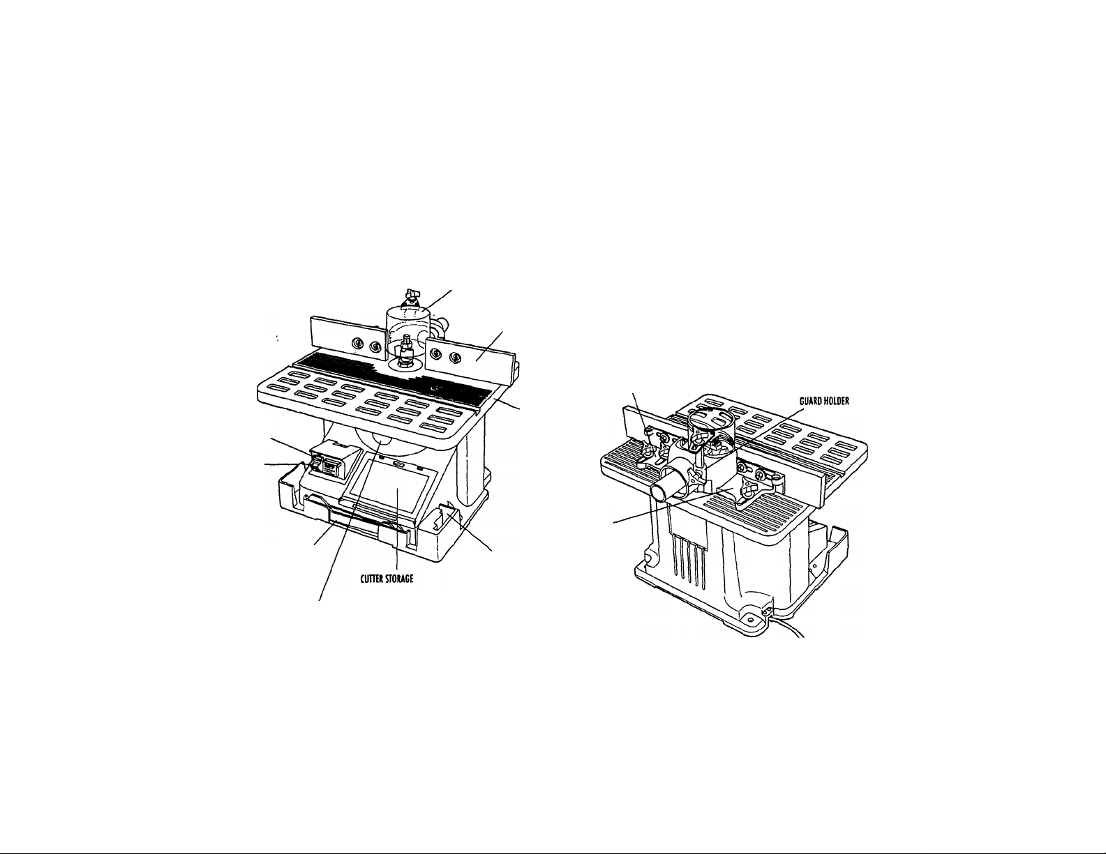
Figure 6 illustrates clear plastic guard assembly. Insert the guard bar
into the guard holder on the rear position of the fence center yoke, and
install a 23mm (0.9") plastic knob into the side of the guard holder to
securely hold the guard in place, as shown in Figure 7.
Assembling Table Insert
The table insert is placed in the table, as shown in Figure 8.
Bench Mounting (See Figure on Following Page)
TURN OFF AND UNPLUG SHAPER/ROUTER.
The shaper/router must be mounted firmly to your workbench or other
anchored frame. Four holes are provided in the tool's feet for this
CEHTER
YOKE
immFIAT
WASHERS
HEX NUTS
FENG
luaEi
WOODEN FENCE
BOARDS
Page 8

6mm FIAT
WASHER
30mm PIASTIC KNOBS
CLEAR
PLASTIC
GUARD
Bench Mounting
TABLE
INSERT
CLEAR
Page 9

purpose. These holes should be used to anchor the shaper/router to
your workbench or other stationary rigid frame. Alternately, to
enhance portability, if can be mounted to a piece of wood that can be
"C" clamped to your work surface or Workmate® Workcenter.
CAUTION: Failure to permanently mount or "C" clamp the
shaper/router to the work surfoce con be hazardous.
When changing the direction of rotation, be sure to turn the cutter
over as necessary to assure that all cutting is done by feeding the work
against the rotation of the cutter. Be sure to close the plastic cover
before turning the tool on.
Only shaper bits which can be inverted can be used for left to right
cutting. Router bits can only cut from right to left.
Operating Controls and Adjustments
SWITCHES (FIGURES 9 AND 10)
We suggest that when the tool is not in use, the switch be locked in the
OFF position.
The switch is located on the Shaper/Router as shown in Figures 9
and 10. To turn the tool ON, flip the toggle upward. To turn the tool
OFF, flip the toggle down. The switch will stay in either position without
being held. For safety, the red switch toggle may be removed when the
switcn is in the locked OFF position. This will prevent unintentional
starting by others.
FORWARD/REVERSE SWITCH
The forward/reverse switch is provided for reversing the direction of
the cutter when it is desirable to work from left to right rather than right
to left. To reverse the cutter direction from counterclockwise (working
from right to left) to clockwise (working from left to right) or vice-verse,
turn the tool off and raise the plastic door over the forward/reverse
switch. Depress the left side of the switch for counterclockwise rotation
, and the right side for clockwise rotation.
Raising and Lowering the Spindle
The spindle can be raised or lowered on your machine for the
purposes of mounting and removing bits and cutters and for cutting at
various heights. To raise or lower the spindle, turn the handle end
counterclockwise to loosen it and then swing it to the right to raise the
spindle and left to lower it, as shown in Figure 11. When it has been
adjusted to the desired height, turn the handle end clockwise to lock it
into position.
Adjusting the Fence
Begin by positioning the fence so that the bit or cutter is located
directly between the wooden fence boards and that the boards are as
close to the guard as possible without touching it.
ctmiHG
e
FENCE
BRACKET
KNOB
WOODEN FENCE BOARDS
DEPTH
HANDLE
<D
0
Page 10

GUARD
(LAMPING
KNOB
16mm FUSTIC KNOB
ROUTER BIT
COLLET NUT
WRENCH STORAGE
CLEAR
FUSTIC
GUARD
STORAGE
DRAWER
BURING GUIDE
The left board on tbe fence is the moveable one. By loosening the
fence bracket knob on the fence bracket, the board can move forwards
or backwards, thus adjusting the position of the fence (see Figure 12).
Actual fence settings far various jobs are presented later in this manual.
Clear Plostic Guard
The clear plastic guard should always be used when cutting with the
fence. To set the guard for maximum effect, loosen the guard clamping
knob and slide the guard down between the wooden boards as far as
it will go without touching the work, as shown in Figure 13. Tighten the
knob securely.
When you are working without the fence an auxiliary guard is
provided which attaches to the rear edge of the table using the
(2) 16mm plastic knobs. It is adjusted and positioned just like the
guard that's mounted on the fence, as shown in Figure 14.
Wrench Storage
The Shaper/Router is supplied with two wrenches. When not in use,
the wrenches can be stored safely out of the way in the slot at the front
of the base. Also, extra cutters can be stored in the drawer shown in
Figure 15.
Installing Router Bits
1. Turn off machine and remove the switch toggle to lock switch off.
2. Install desired collet and collet nut as shown in Figure 16. Screw
collet nut (with collet inside it) down onto spindle. DO NOT
TIGHTEN THIS OR ANY COLLET WITHOUT A BIT IN PLACE. YOU
WILL CRACK THE COUfT.
3. Insert the desired router bit as far as it will go. Then pull it out about
1/16" (1.6mm) and tighten the collet nut firmly using the wrenches
provided, in order to tighten the collet nut, two flats have been
provided on the spindle. These flats are accessible only through the
spindle height adjustment slot below the table. Adjust the spindle
height to maximum by sliding the adjustment handle to the right as
far as it will go. Put one wrench through the slot and onto the flats
and the other on the collet nut, as shown in Figure 17.
Page 11

HINT; To best see the flats and your wrench, remove the table insert
and view through the top of the table. Reinstall table insert before use.
Starting Pin
A starting pin is supplied with your Shaper/Router and is used to
support the workpiece ot the start of the cut when using the
Shaper/Router without the fence. Install the starting pin as shown in
Figure 18. Make sure auxiliary guard is in place furore use.
Installing the Shaper Spindle and Shaper Cutter (Figure 19)
An accessory 1 /2" (12.7mrh) shaper cutter spindle that
accommodates 1 /2" (12.7mmj bore shaper cutters is supplied for
use with your Shaper/Router and can be installed as follows:
1. MAKE CERTAIN THE MACHINE IS DISCONNECTED FROM THE
POWER SOURCE.
2. Raise tool spindle as far as it will go and lock the cutting
depth handle.
3. Select shaper spindle and shaper spindle nut. Thread shaper
spindle into small diameter threads in shaper spindle nut.
4. Screw shaper spindle into shaper spindle nut until the shaper
spindle shoulder protrudes approximately 1 /16" (1.6mm) above
the face of the shaper spindle nut, as shown in Fig. 19B. Maintain
this position as you install the shaper spindle to the tool spindle.
5. Insert tapered end of shaper spindle into tapered end of
tool spindle.
6. Tighten the nut securely to tool spindle using the same means you
used for tightening the collet nut.
7. Install the desired cutter. The cutter must have a 1 /2“ (12.7mm)
hole or bushings (supplied by cutter manufacturer) to reduce the
hole to 1/2" (12.7mm). When installing the shaper cutter use the
appropriate combination of supplied spacers to raise or lower the
shaper cutter. Use the appropriate collar for your cutter when
shaping without the fence. The cutting depth handle can also be
used to adjust the height.
For detailed instructions on cutter Installation, refer to instructions
provided by cutter manufacturer.
piu
0
Page 12

0
BOTH Of CUT
CUiriNGCInaf
Operation
The following is an example of the setup and operational procedures
when using the fence, collars and starting pin. Please review this
information carefully before turning on the power to avoid damage to
the machine or personal injury.
m
0
COlUR
OUTFEED FENCE
CORREa
WORKPIECE
TABLETOP
INFEED FENCE
INCORREa
CUTTER
WORK
Shoping or Routing When Using the Fence as a Guide
Using the fence is the safest and most satisfactory method of shaping
and routing and this method should always be used when the work
permits. Almost all straight work con be shaped using the fence as follows:
1. For average work, where a portion of the original edge of the work
is not touched by the cutter, both the front and rear fences are in a
straight line, as shown in Figure 20.
2. When the operation removes the entire edge of the work, e.g., in
jointing or making a full bead, the shaped edge will not be
supported by the rear fence when both fences are in line, as shown
in Figure 21. In this case, the work should be advanced to the
position shown in Figure 21 and stopped. Then turn the machine off.
3. The outfeed fence and infeed fence should then be adjusted to
contact the work, as shown in Figure 22. The outfeed fence will
then be in line with the cutting circle. Refer to Figure 12 which
illustrates "Adjusting the Fence."
NOTE; When cutter rotation is reversed from that shown in
Figures 20, 21 and 22, feed direction will also be reversed
and infeed and outfeed fence identification will reverse.
4. Avoid heavy cuts. Begin by positioning cutter and fence to remove
only a small portion of the final cutter form. Increase cutter
exposure with each successive pass by moving fence and/or cutter
height until desired form is cut on workpiece. After gaining
experience with a particular cutter, you will learn how many passes
with accompanying fence and cutter adjustments are necessary to
produce a safe and satisfactory result. Remember, taking loo great
a cut or feeding the workpiece too fast can cause damage to the
piece and loss of control with possible injury.
5. When beginning the shaping operation, apply most pressure to that
portion of the workpiece supported by the infeed fence taking care
to keep your hands safely away from the cutter. When more than
to
Page 13

half of the workpiece has passed the cutter, transfer most pressure
to that portion now supported by the outfeed fence. Never apply
pressure to the workpiece in the area between fences. This will
prevent the workpiece from kicking in toward the cutter when its
trailing edge leaves the infeed fence and prevent loss of control and
possible injury.
Shaping or Routing With Collars and Starting Pin
A collar or bearing guide must be used when cutting if the fence
assembly is removed. The following rules must always be followed for
good work and safety in operation.
1. Collars MUST be smooth and free of all gum or other substances.
2. The edge of the work to be shaped MUST be smooth, as any
irregularity in the surface which rides against the collar will be
duplicated on the moulded surface.
3. A portion of the edge of the work MUST remain untouched by the
cutters in order that the collar will have sufficient bearing surface.
Figure 23 illustrates the right way for the operation while
Figure 24 illustrates the wrong way.
4. The workpiece MUST be fairly wide in proportion to the cut being
made as shown in Figure 25. Under NO circumstances should short
workpieces of narrow material be shaped against the collars as
shown in Figure 26.
5. when routing with collars and starting pin, the overhead cutter
guard, supplied with your machine, should always be used.
POSITION OF COLLARS
1. The collars may be used in any of the following positions: above,
below or between two cutters.
■2. When the collar is used below the cutter, as shown in Figure 27, the
progress of the cut can be observed at all times. However, any
accidental lifting of the work will gouge the wood and ruin
the workpiece.
3. When the collar is used above the cutter as shown in Figure 28, the
cut cannot be seen, yet this method offers some advantage in that
the cut is not affected by slight variations in the thickness of
the stock.
STARTING PIN
2ND POSITION
3RD POSITION
Page 14

4. The collar behveen cutters method, as shown in Figure 29, has both
the odvantages of the first two methods and is frequently used
where both edges of the work are to be shaped.
Starting Pin
1. Your machine is supplied with a starting pin which is used as a
support when starting the cut. The starting pin is placed into the
threaded hole in the table.
2. The work should be placed in the first position using the starting pin
as a support, as shown in Figure 30. Then swing the work into the
cutter as shown in the second position. The work will now be
supported by the collar and starting pin as shown in Figure 30.
3. After the cut has been started, the work is swung free of the starting
pin and rides only against the collar as shown in the third position
Figure 31.
ALWAYS FEED AGAINST THE ROTATION OF THE CUTTER.
IMPORTANT; If the work would be advanced to the cutter without the
side support of the starting pin, it would invariably be kicked back.
Accessories
Recommended accessories for use with your tool are available at
extra cosf from your local dealer or authorized service center.
CAUTION: The use of any accessory not recommended for use with
this tool could be hazardous. Use only cutters that are rated above
10,000 RPM and equal to or less than 2-1/2" (63.5mm) diameter.
If you need assistance in locating any accessory, please contact:
Black & Decker (U.S.) Inc.
Consumer Service Dept.
626 Hanover Pike, P.O. Box 618
Hampstead, MD 21074-0618
Phone: 1-800-762-6672
To purchase Black & Decker bench tool accessories, which are not
available at your local retailer, please call Black & Decker Teleservice
at 1-800-258-6003.
Important
To assure product SAFETY and REUABIUTY, repairs, maintenance and
adjustment (including brush inspection and replacement) should be
performed by authorized service centers or other qualified service
organizations, always using identical replacement parts.
Full Two-Year Home Use Warranty
Black & Decker (U.S.) Inc. warrants this product for two years against
any defects thot are due to faulty material or workmanship. Please
return the complete unit, transportation prepaid, to the seller (if a
participating retailer) for free replacement (proof of purchase may be
required). This unit may also be returned to a Black & Decker service
center or authorized service station, listed under "Tools-Electric" in the
yellow pages for free replacement or repair at our option. This
warranty does not apply to accessories. This warranty gives you
specific legal rights and you may have other rights which vary from
state to state. Should you have any questions, contact your nearest
Block & Decker service center manager.
This product is not intended for commercial use.
Every Black & Decker tool is of the highest quality. If you wish to
contact us regarding this product, please call toll free between
8:00 a.m. and 8:00 p.m. ET, seven days a week.
1-800-762-6672
Imported by
Black & Decker (U.S.) Inc.,
701 E. Joppa Ro.
Tovrson, MD 21286 U.S.A.
Sm'Tool»-EI*ctrlc'
- Yellow Peges -
Tor Service 1 Selee
12
 Loading...