

Page 1
IMf
IC&DEGKER.
.322765
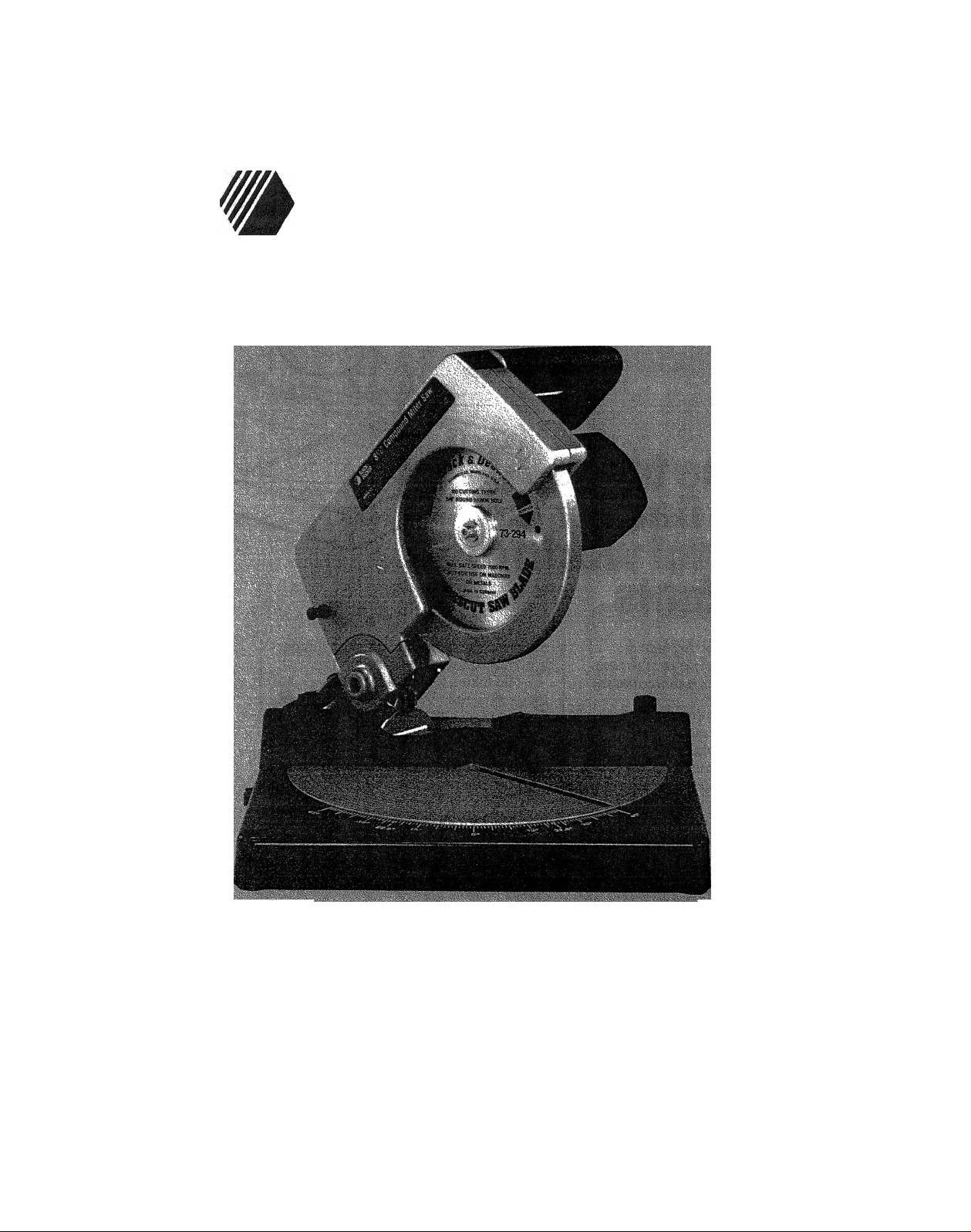
Instruction Manual
8W' Compound Miter Saw
9425
Page 2
Welcome to
Black & Decker’s
wonderful world of
PowerTools.
If you already own a Black &
Decker Power Tool you know the plea
sures a high quality, high perforrhance
power tool can deliver.
Your new Compound Miter Saw
has been carefully engineered and built
to Black & Decker’s high standards for
quality and dependability. It’s built to last
for many years of tough, trouble-free
service and high quality performance.
It can cut wood, plastics and com
positions. Use it for straight cuts, miters,
bevels or compound miters. Its tough,
die cast aluminum rotating table locks
firmly in place for accurate cutting of
BlACKSiDECKER
#
molding, trim work, construction lumber
and even plastic pipe
So take a few minutes and
thoroughly read this instruction manual.
Pay particular attention to the Safety
Rules we’ve provided for your
protection.
We want you to enjoy your
Compound Miter Saw, and the more
you know about it, and its capabilities,
the happier you’ll be with it.
Thank you for selecting Black &
Decker.
And don’t forget to send in your
owner’s registration card.
f.
Page 3

SAFETY INSTRUCTIONS
WARNING: When using Electric Tools, basic safety precautions should always be followed to reduce
the risk of fire, electric shock, and personal injury, including the following:
READ ALL INSTRUCTIONS
1. KEEP GUARDS IN PLACE and in working order.
2. REMOVE ADJUSTING KEYS AND WRENCHES. Form habit of checking to see that keys and adjusting
wrenches are removed from tool before turning it on.
3. KEEP WORK AREA CLEAN. Cluttered areas and benches invite injuries.
4. DON’T USE IN DANGEROUS ENVIRONMENT. Don’t use power tools in damp or wet locations, or
expose them to rain. Keep work area well lighted.
5. KEEP CHILDREN AWAY. All visitors should be kept a safe distance from work area.
6. MAKE WORKSHOP KID PROOF with padlocks, master switches, or by removing start keys.
7. DON’T FORCE TOOL. liVvill do the job better and safer at the rate for which it was designed.
8. USE RIGHT TOOL. Don't force tool or attachment to do the job for which it was not designed.
9. WEAR PROPER APPAREL. Don’t wear loose clothing, gloves, neckties, rings, bracelets, or other jewelry
that could get caught in moving parts. Nonslip footwear is recommended. Wear protective hair covering to
contain long hair.
10. ALWAYS WEAR SAFETY GLASSES. Also use face or dustmask if cutting operation is dusty. Everyday
eyeglasses have only impact resistant lenses, they are NOT safety glasses.
11. SECURE WORK. Use clamps or vise to hold work when practical. It’s safer than using your hand and it
frees both hands to operate tool.
12. DON'T OVERREACH. Keep proper footing and balance at all times.
13. MAINTAIN TOOLS WITH CARE. Keep tools sharp and clean for best and safefet performance. Follow
instructions for lubricating and changing accessories.
14. DISCONNECT TOOLS before servicing, and when changing accessories such as blades, bits, cutters, or
when clearing away sawdust..
15. REDUCE THE RISK OF UNINTENTIONAL STARTING. Make sure switch is in OFF position before
plugging in.
16. USE RECOMMENDED ACCESSORIES. Consult the instruction manual for recommended accessories.
The use of improper accessories may cause risk of injury to persons.
17. NEVER STAND ON TOOL. Serious injury could occur if the tool is tipped or if the cutting tool is
unintentionally contacted.
18. CHECK DAMAGED PARTS. Before further use of the tool, a guard or other part that is damaged should
be carefully checked to determine that it will operate properly and perform its intended function—check for
alignment of moving parts, binding of moving parts, breakage of parts, mounting and any other conditions
that may affect its operation. A guard or other part that is damaged should be properly repaired or replaced.
19. NEVER LEAVE TOOL RUNNING UNATTENDED. TURN POWER OFF. Don't leave tool until it comes
to a complete stop.
20. DO NOT OPERATE ELECTRIC TOOLS NEAR FLAMMABLE LIQUIDS OR IN GASEOUS OR
EXPLOSIVE ATMOSPHERES. Motors in these tools may spark and ignite fumes,
21. For your own safety, READ INSTRUCTION MANUAL before operating your miter saw.
22. KEEP HANDS OUT OF PATH OF SAW BLADE.
23. DO NOT ATTEMPT ANY FREE HAND CUTTING with this saw.
24. NEVER REACH around or behind saw blades.
25. SHUT OFF POWER AND WAIT FOR SAW BLADE TO STOP before servicing opadjusting the saw.
SAVE THESE INSTRUCTIONS FOR FUTURE USE.
REFER TO PAGE 4 FOR ADDITIONAL SAFETY NOTES.
Page 4

Additional Safety Rules For The Compound Miter Saw
1. DO — Protect line with at least a 15
ampere time delay fuse.
2. DO — Make certain the balde
rotates in the correct direction.
3. DO — Be sure all clamp handles are
tight before starting any operation.
4. DO — Be sure blade and arbor col
lars are clean and recessed side of
collars are against blade. Tighten
arbor screw securely.
5. DO — Keep saw blade sharp and
properly set.
6. DO — Keep motor air slots clean
and free of chips.
7. DO — Use both upper and lower
blade guards at all times.
8. DO — Operate only on designated
voltage and frequency.
9. DO — Tighten all clamps before
operating.
10. DO — Use blades of recommended
size only.
11. DO — Hold motor shaft/saw blade
only as instructed in this manual.
12. DO — Operate in dry environment
only.
13. DO — Allow motor to reach full
speed before cutting.
14. DO — Keep visitors clear.
15. DO — Keep hands clear of blade
area when saw is plugged in.
16. DO — Use blades recommended for
operation at greater than 3600 RPM
only.
NOTE: This saw should NOT be
used to cut ferrous metals or masonry.
NOTE: This saw should NEVER be
used to reçut small pieces.
Electrical Connection
Your Miter Saw is powered by a
Black & Decker built motor. Be sure your
power supply agrees with the nameplate
marking. 120 Volts, 60 Hz or “AC only"
means your tool must be operated only
with alternating current and NEVER with
direct current. A voltage decrease of
more than 10% will cause loss of power
and overheating. All B&D tools are fac
tory tested; if this tool does not operate,
check the power supply.
Double-Insulation
Your tool is double insulated to give
you added safety. This means that it is
constructed throughout wtih TWO
separate “layers” of electrical insulation
or one DOUBLE thickness of insulation
between you and the toot’s electrical
system.
Tools built with this improved insula
tion system are not intended to be
grounded. As a result, your tool is
equipped with a two-prong plug which
permits you to use any conventional 120
volt electrical outlet without concern for
maintaining a ground connection.
NOTE: Double-Insulation does not
take the place of normal safety precau
tions when operating this tool. The
improved insulation system is for added
protection against injury resulting from a
possible electrical insulation failure within
the tool.
CAUTION; When servicing
Double-Insulated Tools, USE ONLY
IDENTICAL REPLACEMENT PARTS.
Replace or repair damaged cords.
This tool Is intended for residen
tial use only.
Extension Cords
When using the tool at a considera
ble distance from the power source, an
extension cord of adequate size must be
used for safety, and to prevent loss of
power and overheating. Use the table
below to determine minimum wire size
required.
Before using cords, inspect them for
loose or exposed wires and damaged
insulation. Make any needed repairs or
replacement before using your power
tool.
Chart For Minimum Wire Size
(AWG) of Extension Cords
Total Extension Cord
Length - Feet
25 50 75 100
120 Volt 16
Tools
NOTE: The lower the wire size num
ber. the heavier the wire, and the farther it
will carry current without a significant volt
age drop.
14
12
10
Unpacking Your Saw
Inspect the contents of your saw
carton. In addition to this instruction
Manual, you should find the following:
1. One #9425 Compound Miter Saw
2. One plastic wing knob, packed inside
cardboard filler block next to blade
Page 5

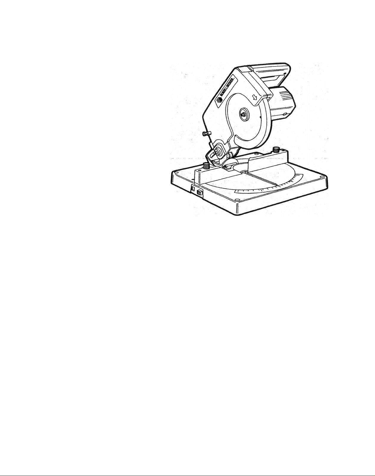
Setup
FAMiLiARiZATION: Place the Miter
Saw on a flat, strong and level surface,
and examine it to become familiar with
the terminology used to describe its var
ious parts. (See Figures 1 and 2.)
UNLOCKING THE PIVOT ARM:
Your saw was shipped from the factory
with the pivot arm in the locked down
position This position is used to facilitate
packaging and for storage.
■'table-'
To release the pivot arm, remove
the cardboard filler block from the saw
table, grasp the switch handle with one
hand and the end of the lock pin with the
other, as shown Figure 3. Push down
on the switch handle lightly and pull out
on the lock pin. When the pin is out as far
as it will go. raise the pivot arm to its full
height. (The saw will look tike the picture
■ Mtierta tcb:' T;L
Bench Mounting
Before using your miter saw. it must
be firmly mounted to your workbench or
other rigic^frame. Four holes are provided
in the base of the saw for this purpose.
To mount the saw, position it as
desired (don’t forget about the availability
of an electrical outlet), and mark the posi
tions of the four holes in the saw.
Remove the saw and drill four pilot holes
in the places you marked. Reposition the
saw over the holes and secure it to the
workbench using t/4" x 1-374'’ wood
screws, as shown in Figure 5. (Do not
overtighten.)
Page 6

An alternate mounting nnethod that
will enhance the saws portability is to
mount the saw on a piece of 1 /2" or
thicker plywood. The saw can then be
taken to remote locations and the ply
wood clamped in place with a couple of
large "C” damps.
Miter Table and
Miter Scale
The miter table and miter scale
permit you to set accurate miters up to
45° left or right.
SETTING THE MITER TABLE: Follow the
steps below to set any miter angle.
1. TURN OFF AND UNPLUG THE
SAW.
2. Loosen the two miter damp knobs
shown in Figure 5 (About 1 /4 turn
counter-clockwise.)
3. Push in the miter latch, shown in Fig
ure 6 and. using the switch handle as
a grip, rotate the saw around until the
miter pointer (FigureG ) aligns with the
desired setting on the miter scale, also
shown in Figure 6.
4. The miter scale is graduated in incre
ments of one degree {1 °). The exam -
pie shown in Figure 7 is 35^,
5. When you have set the desired angle,
lock it in place by tightening the two
miter damp knobs that you loosened
in Step 2 above.
NOTE: The miter latch v,/ili automat
ically lock the miter table at 0°. 22-1/2°
left and right and 45° left and right. Even
in these locked miter positions, you
should tighten the two miter damp
knobs.
Setting the Bevel Post
Follow the steps below to set any
bevel angle.
1. TURN OFF AND UNPLUG THE
SAW.
2. Install the plastic wing knob (packed
inside cardboard filler block next to
blade) on the splined shaft, as shown
in Figure 8, (Make sure it is straight up.
as shown.)
Switch
To turn the tool ON. squeeze
and hold the trigger switch shown in
Figure 9 .
To turn the saw OFF. release
the trigger switch.
Page 7

Miter
Scale
Lower
Blade Guard
Miter
Clamp Knob
Cutting Tips
WEAR EYE PROTECTION.
The smoothness of any cut de
pends on a number of variables. Things
like materia! being cut. blade type, blade
sharpness and rate of cut all combine to
affect the quality of the cut.
When cutting framing lumber or
other types of lumber where cut smooth
ness IS not a point of concern, high cut
ting rate coupled with a sharp general
purpose blade will produce satisfactory
results.
When smoother cuts are desired, a
sharp blade designed for smooth cuts
and a slow even cutting rate will produce
the desired quality of cut.
For varied cutting applications, refer
to the list of recommended accessories
for your saw and select the blade that
best fits your needs
Replacing Saw Blades
Follow the steps below to replace a
saw blade
1 TURN OFF AND UNPLUG THE
SAW.
2 Allow the saw arm to raise to its full
3. Using the hex wrench located in the
saw table, shown in Figure 10. loosen
hex screw *'A‘* in Figure 11 tour full
turns counter-clockwise.
. Using the same hex wrench, remove
the arbor screw in the center of the
motor shaft. (Left hand thread; turn
clockwise to loosen.) NOTE: Place a
screwdriver or large nail through the
hole in the saw blade (see Figure 12)
to hold it while you tighten or loosen
the screw. BE SURE TO REMOVE
IT WHEN YOU FINISH.
Operation
WEAR EYE PROTECTION.
To cut a piece of wood, first
determine that it's the right size for
the saw. Place the wood on the saw
table and hold it firmly against the
fence. If the piece you're working
with is smaller than 6" long and
would cause your hand to be within
6" of the saw blade. TURN OFF
AND UNPLUG THE SAW and
clamp the wood to the fence before
cutting it.
Do not attempt to hold small
pieces. NEVER ATTEMPT ANY
FREE HAND CUTTING WITH
THIS SAW. (Free hand cutting is
cutting wood that is not held
firmly against the fence and the
saw table. Support long work with
an outboard work rest.)
Page 8

6. Remove the old blade and insiall the
new one taking care to orient the two
blade washers carefully, as shown in
Figure 13.
piiillliiiililiiiK
il'"
1©
7. Manually tower the blade guard as far
as it will go.
8. Tighten hex screw ‘’A * clockwise until
tight. (DO NOT OVER-TIGHTEN.)
Replace the hex wrench in the saw
table.
The example in Figure A is a joint
made by using the bevel adjustment to
bevel the edges of the boards (at 45°
each) to form a 90° miter corner. For this
operation, set the bevel post adjustment
at 45° and the miter table adjustment at
0°. Position the wood with the broad flat
side against the table and the narrow
edge against the fence.
The example shown in Figure B
is a joint made by using the miter table
adjustment to miter the width of the board
(at 45° each) to form a miter corner of
90°. For this operation, set the bevel post
adjustment at 0° and the miter table
adjustment at 45°. Position the wood with
the broad flat surface against the table
and the narrow edge against the fence.
NOTE: The examples shown and
discussed above are for four-sided fig
ures only. The chart in Figure 15 shows
the setting for the miter table or bevel
post for several different shapes.
Observe that the angle of cut decreases
as the number of sides increases. These
angles are derived from the formula:
180° T number of sides in desired object
= miter angle for each joint
FIG. 15
Cutting
Compound Miters
A compound miter is a cut made
using both a miter setting (made by
adjusting the miter table) and a bevel set
ting (made by adjusting the bevel post).
The resulting cut is a beveled (or com
pound) miter. These cuts are used for
making frames or boxes with sloping
sides like those shown in Figure 16. The
important thing to remember when mak
ing compound miters is that the adjust
ments of miter and bevel are inter
dependent with one another. Each time
you adjust the miter table you change the
bevel setting; and every adjustment to
bevel changes the miter setting, it may
take several settings to obtain the
desired cut. ALWAYS MAKE TEST
CUTS IN SCRAP MATERIAL
BEFORE ATTEMPTING FINISHED
WORK.
Picture Frames,
Shadow Boxes &
Similar Four-Sided
Projects
For a more thorough understanding,
we suggest that you perform these cuts
using scrap wood. Your new saw is the
perfect tool for making closed objects
where it’s necessary to join wood sides
and construct corners. Figure 14 shows
two typical types of mitered corners.
NO.
SIDES
-
... 9.......
10
EXAMPLES —
—
4
5
6
■•■s ■ 30°
7
8
.
ANGLE
MITER OR BEVEL
45°
36°
26.7°
22.5°
---20^—::
............
18°
...
Page 9

Cutting Crown Molding
Your Compound Miter Saw is probably better suited to the difficult task of cut
ting crown molding than any other tool made. In order to fit properly, crown mold
ing must be compound mitered with extreme accuracy (see Figure 17).
The two surfaces on a piece of crown molding that fit flat against the ceiling
and the wail of a room are at angles that, when added together, equal exactly 90"^.
Most crown molding has a top rear angle (the section that fits flat against the ceil
ing) of 52° and a bottom rear angle that fits flat against the wail of 38°.
In order to accurately cut crown molding for a 90° inside or outside comer,
refer to the chart that follows.
FOR ALL CUTS:
1. Molding laying with broad back surface down flat on saw table
2. The settings below are for All Standard (U.S.) crown molding with 52° and 38°
angles.
BEVEL POST
SETTING
33.85°
33.85°
33.85°
33.85°
When setting bevel post and miter table angles for all compound miters,
remember that:
1. The settings are interdependent so that changing one changes the other as
well, and
2. The angles presented for crown moldings are very precise and difficult to set
exactly. Since they can easily shift slightly and very few rooms have exactly
square corners, ail settings should be tested on scrap molding.
PRETESTING WITH SCRAP MATERIAL (S EXTREMELY IMPORTANT!
LEFT SIDE, INSIDE CORNER;
1. Top of molding against fence
2. Miter table set right 31.62°
3. Save left end of cut
RIGHT SIDE. INSIDE CORNER:
1. Bottom of molding against fence
2. Miter table set left 31.62°
3. Save left end of cut
LEFT SIDE, OUTSIDE CORNER:
1. Bottom of molding against fence
2. Miter table set left 31.62°
3. Save right side of cut
RIGHT SIDE. OUTSIDE CORNER:
1. Top of molding against fence
2. Miter table set right 31.62°
3. Save right side of cut
TYPE OF CUT
______
Page 10

Accessories
The accessories fisted in this manual are available at extra cost from
your local dealer or Black & Decker Service Center.
A complete listing of service centers is included on the owner's
registration card packed with your tool.
If you need assistance in locating any accessory please contact:
Black & Decker (U.S.) Inc.
User Services Department
10 North Park Drive
P.O. Box 857
Hunt Valley. MD 21030>0857
Saw Biades
Lubrication and
Maintenance
Permanently lubricated bearings
are used throughout your Miter Saw and
periodic lubrication is not required. In the
unlikely event that service is ever re
quired, take your saw to your closest
Black & Decker Service Center as listed
on your Owner's Registration card. Do
not attempt to repair the saw yourself,
there are no user serviceable parts
inside.
Cat. No.
73-291
73-293 8-1 /4"
73-294
73-390
73-391
Diameter Arbor Size/Description
8-1/4"
5/8"' General purpose combination
5/8" Premium hollow ground planer
8-1/4"
8-1/4"
8-1/4"
Crosscut miter
5/8"
Carbide tipped carbide (20 tooth)
5/8"
Carbide tipped carbide (40 tooth)
5/8"
Other Accessories
72-000 Safety Glasses
The accessories listed above are recommended for use with your #9425
8-1 /4 in. Compound Miter Saw. THE USE OF ANY OTHER ACCESSORY OR
ATTACHMENT MAY BE HAZARDOUS.
NOTE: A vacuum port on the blade guard is designed to accept a standard
1 -1 /2" diameter vacuum cleaner hose for dust collection.
10
Page 11

NOTES
Page 12

Black & Decker’s Full Two Year Home Use Warranty states that, in case of a
defect, you may return the tool to the place of purchase for a free replacement (if it
is a participating retailer) or you may take it to a Black & Decker Service Center.
Home Use Warranty
(A Full Two Year Warranty)
Black & Decker (U.S.) Inc. warrants this product for two years against any
defects that are due to faulty material or workmanship. Please return the complete
unit, transportation prepaid, to the seller (if a participating retailer) for free
replacement (proof of purchase may be required). The unit may also be returned to
a Black & Decker Service Center or Authorized Service Station listed under “Tools
Electric” in the Yellow Pages for free replacement or repair at our option. This
warranty does not apply to accessories. This warranty gives you specific legal
rights and you may have other rights which vary from state to state. Should you
have any questions, contact your nearest Black & Decker Service Center Manager.
Like most Black & Decker tools, your Miter Saw is listed by Underwriters
Laboratories to ensure that it meets stringent safety requirements.
This symbol on the nameplate means the product
is Listed by Underwriters’ Laboratories. Inc.
See Tools-Electric’
—Yellow Pages—
for Service & Sales
#
(AUG87) ©1987 Printed in W. Germany
BIMiKGilECKER.
BLACK & DECKER (U.S.) INC., U.S. Power Tools Group, 10 North Park Drive, P.O. Box 798, Hunt Valley, MD, 21030-0798 U.S.A,
Product Made in W. Germany
Form No. 741169-01
 Loading...