

TM
LED UNDER CABINET LIGHTING
INSTRUCTION MANUAL
CATALOG NUMBERS
LEDUC9-1WB
LEDUC9-1CB
LEDUC-25JUMP
Thank you for choosing BLACK+DECKER!
PLEASE READ THIS MANUAL BEFORE RETURNING THIS
PRODUCT FOR ANY REASON.
If you have a question or experience a problem with your BLACK+DECKER
purchase, go to PureOpticsLED.com/Support. If you can’t find the answer or do
not have access to the internet, call 1-855-784-4322 from 8 a.m. to 5 p.m. Monday
– Friday to speak with an agent. Please have the catalog number available when
you call. To find the catalog number, please refer to product packaging.
SAVE THIS MANUAL FOR FUTURE REFERENCE.
To register your new product visit
PureOpticsLED.com/New-Product
SAFETY GUIDELINES - DEFINITIONS
I
t is important for you to read and understand this manual. The information it contains relates to protecting YOUR SAFETY and PREVENTING
PROBLEMS. The symbols below are used to help you recognize this information.
DANGER: Indicates a imminently hazardous situation, which, if not avoided, will result in death or serious injury and/or property damage.
WARNING: Indicates a potentially hazardous situation, which, if not avoided, could result in death or serious injury and/or property damage.
CAUTION: Indicates a potentially hazardous situation, which, if not avoided, may result in minor or moderate injury and/or property damage.
NOTICE: Used without the safety alert symbol indicates potentially hazardous situation which, if not avoided, may result in property damage.
IMPORTANT SAFEGUARDS
BLACK+DECKER LED Under Cabinet Lights are intended for indoor home and ofce use and have not been tested for operation at different
voltages or use outdoors. Each of these misuses could damage the light and/or create unsafe operating conditions.
TO REDUCE THE RISK OF INJURY
Before any use, be sure everyone using this light reads and understands all safety instructions and other information contained in this manual.
CAUTION
WARNING:
shock, fire, and/or serious injury.
: Failure to comply with the recommendations outlined in this instruction manual will void warranty.
Read all safety warnings and all instructions. Failure to follow the warnings and instructions may result in electric
SAVE ALL WARNINGS AND INSTRUCTIONS FOR FUTURE REFERENCE
WARNING:
serious injury and/or property damage.
• Use indoors and in dry locations only; keep all liquids away from the light.
• Do not alter or modify the light, ground plug, or polarized plug blades.
• Do not use light with other adapters or voltage supplies.
• Do not attempt to disassemble light; product is to be serviced by qualied service personnel only—there are no user serviceable parts inside.
• Always power off and unplug light before cleaning.
• Clean exterior only with a dry, clean cloth; do not immerse light in water to clean.
• Do not insert objects into light.
• If any irregularities are detected during use, turn off the switch and unplug the light.
WARNING:
and/or property damage:
• Avoid usage in high temperature areas.(104°F/40°C)
• Avoid putting light next to heater.
• Lights should not be covered with ammable objects (cloth, paper, etc.)
CAUTION:
moderate injury:
•
Dispose of task lights in accordance with applicable local government regulations.
To reduce the risks associated with impact and hazardous voltage which, if not avoided, could result in death or
To reduce the risks associated with excessive heat and re which, if not avoided, could result in death or serious injury
To reduce the risks associated with environmental contamination which, if not avoided, could result in minor or
WARNING
•
This device may not cause harmful interference.
• This device must accept any interference recieved, including interference that may cause undesired operation.
INTENDED USE: BLACK+DECKER LED Under Cabinet Lights are intended to provide task lighting indoors. Use in any other
application has not been evaluated and may lead to an unsafe condition.
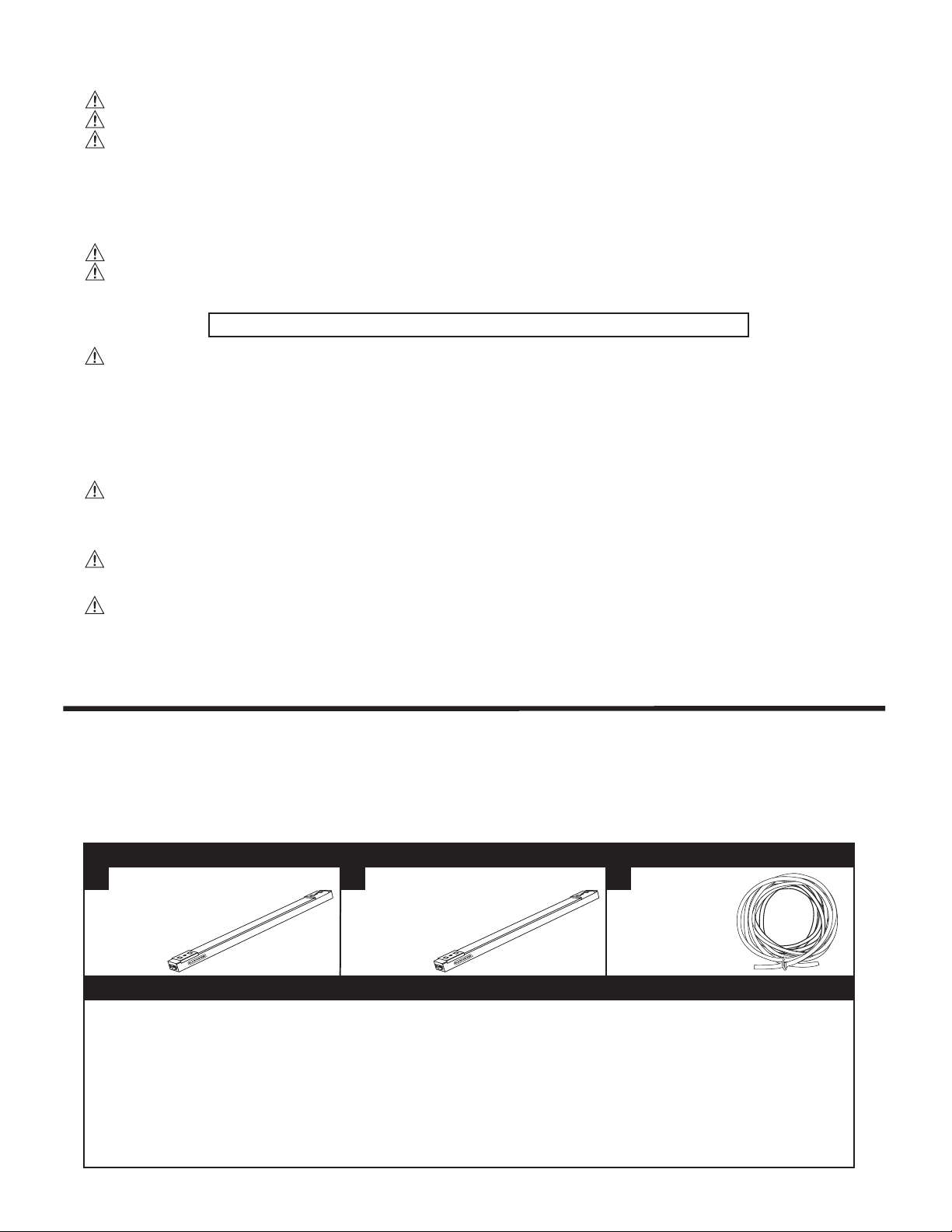
SYSTEM OVERVIEW
This product is designed and will only work with all three components listed below: LIGHT BARS, WIRE and a POWER SUPPLY.
Each are sold separately. Please ensure you have purchased all three system components before starting your project.
FUNCTIONAL DESCRIPTION
LIGHT BARS
A B C
LEDUC9-1WB
LED Under Cabinet Light Bar, 9 in.
Lumens: 310
Watts: 4
CRI: 81
CCT: 2700K
LEDUC9-1CB
LED Under Cabinet Light Bar, 9 in.
Lumens: 320
Watts: 4
CRI: 82
CCT: 4000K
POWER SUPPLY
For Use with a Class 2 Transformer
24W Power Supply will Power up to 6 Lights
48W Power Supply will Power up to 12 Lights
WIRE
LEDUC-25JUMP
25’ 20AWG Solid
Core Wire

POWERING ON/OFF
Using the Power Button: Press the power button located on the light bar once to turn the lights on. To
turn off, press the power button again. (See FIG. 1)
Using the Motion Sensor: Ensure that your hand is within at least 2” of the motion sensor on the
mounted control box. Wave your hand in any direction underneath the control box to turn the power on
and/or off. (See FIG. 2)
USING THE DIMMER
There are ten (10) preset lighting levels that can be adjusted with the dimmer button. To select your
lighting level, ensure that the system is already powered on. Hold down the button to change the
lighting level and/or switch between the presets. (See FIG. 1)
NOTE: This lighting system has a memory function that will use the last selected brightness level the
next time it is powered on.
FIG. 1
USING THE TIMER
This lighting system is equipped with an optional auto shutoff timer switch that will power the unit off
after three (3) hours. To activate, switch to the “on” position. To disable, switch to the “off” position.
(See FIG. 3
)
PUSH CONNECT INSTALLATION
• The wire can be cut to custom lengths and is used to connect the light bar(s) to the control box and
link light bars together.
• Inside of the wire are two (2) white wires and one (1) gray wire (See FIG. 4); To expose the solid
copper wire, cut approximately 3/8” on each of the three wires.
• After exposing the solid copper wires, connect to the control box or light bar (depending on where
you are in the installation process)
• To connect to the control box or light bar, simply push the copper wires into the connection on the
control box or light bar. (See FIG. 5)
NOTE: The gray wire must always link to the middle connection, while the white wires can
connect to either of the outer connections.
• If connected properly, the wire should hold securely and not disengage.
NOTE: If you need to release a wire from a light bar, remove the end cap to expose the connection
(see FIG. 6) and use the included tool to press and release the copper wires from the light.
APPLICATION OPTIONS
Tool-Free
1. Wipe down the mounting surface with a clean, lint-free cloth.
2. Peel red backing from the adhesive.
3. With the adhesive side facing the mounting surface, place the piece rmly on its desired location
and hold for 5 seconds.
Screw-In
1. Follow the Tool-Free application steps.
2. Remove light bars from bar mounting clips to expose the screw holes. (See FIG. 7)
NOTE: Skip this step for wire clips as the screw hole is already exposed.
3. Drill 7/32” pilot holes through each exposed screw hole. (See FIG. 8)
4. Secure each mounting clip using the provided mounting screws.
FIG. 2
FIG. 3
FIG. 4 FIG. 6
FIG. 5
FIG. 7
CONFIGURATION OPTIONS
Split Conguration: For layouts where preferred power source is centrally located within
cabinets/mounting surfaces. (See FIG. 9)
Continuous Conguration: For layouts where preferred power source is on either side of
cabinets/mounting surfaces. (See FIG. 10)
INSTALLATION TIPS
Optimal Illumination
For cabinets up to 36” in length, one (1) light bar can be used. For cabinets over 36” in
length, two (2) light bars should be used.
Light Bar Placement
Use the spacer provided in your kit to help measure and guide the placement of each light
bar.
Hiding Jumper Wires
Use the included wire clips to hide all loose and hanging wires: To mount the wire clips, use
the Tool-Free or Screw-In application process.
Running Wires Through Cabinets
Jumper Wire: To feed the light bar jumper wire through a cabinet, use a 7/32” drill bit (not
included).
Power Adapter Wire: To feed the power adapter wire through a cabinet, use a 3/8” drill bit
(not included).
Control Box Wire: To feed the control box wire through a cabinet, use a 1/2” drill bit (not
included).
7/32”
7/32”
FIG. 8
FIG. 9
FIG. 10

STEP-BY-STEP INSTALLATION
For additional information, please visit PureOpticsLED.com
It is important and necessary to follow all local and national electrical codes. If you are unsure of your
local codes, please contact your local town or city electrical inspector.
1. Consider layout and conguration
• Determine how many lights you’ll need to install - each light bar is designed to effectively illuminate
cabinets 12”-36”.
NOTE: Keep in mind that each power supply option has a maximum amount of light bars it can
power.
• Determine the location of your control box with hands-free power control; An ideal location is on the
underside of a cabinet in an easily accessible location.
• Determine the location of your power supply (plug-in or direct wire options) and take note of the
length of your power cord, which will connect to the control box.
NOTE: There are several installation methods that can allow for exible placement of your
hands-free on/off control box that are illustrated under CONFIGURATION OPTIONS.
2. Install the control box
• After determining its desired location, follow the Tool-Free application steps (see FIG. 11). Before
mounting, be sure to leave room for the jumper wires, which will connect on one or both sides of the
control box (depending on your conguration).
• Using a 3/8” drill bit, drill holes as needed to connect your control box to the power supply (See
FIG. 12)
PRO TIP: If connecting the control box to the power supply inside of a cabinet, use a 1/2” drill bit to
feed the control box wire into the cabinet.
3. Install the light bars
• Slide two (2) bar mounting clips on to each light bar.
• Using your installation spacer as a guide, mount light bars using Tool-Free or Screw-In application
process. (See FIG. 13)
4. Connect the control box to the nearest light bar
• Cut the desired length of wire needed to connect the control box to the nearest light bar.
• Cut and strip the wire to expose approximately 3/8” of the solid copper wire on each of the three
wires.
• Push the solid copper wires into their respective connections on the control box.
NOTE: The gray wire must always link to the middle connection, while the white wires can connect
to either of the outer connections. (See FIG. 14)
5. Connect the light bars together
• Repeat the process outlined in step 4 to connect two light bars together. (See FIG. 15)
• To hide the jumper wires, route them through the frames of each cabinet by using a 7/32” bit to drill
holes as close to the front of the frame as possible. (See FIG. 16)
6. Hide excess wires
• Use the included wire clips to hide all loose and hanging wires (see FIG. 17); To mount the wire
clips, use the Tool-Free or Screw-In application process.
FIG. 11
FIG. 12
FIG. 13
FIG. 14
FIG. 15
FIG. 16
FIG. 17
THREE-YEAR LIMITED WARRANTY
Amax Inc. warrants to the original retail purchaser that the product purchased is free from defects in material and workmanship, and agrees to
repair or replace, at Amax’s option, any defective BLACK+DECKER™ branded under cabinet lighting product (3) years from the date of
purchase. Warranty is not transferable. Proof of purchase date required. This warranty covers only damage resulting from defects in material
or workmanship; it does not cover conditions or malfunctions resulting from normal wear, neglect, abuse, accident, or repairs attempted or
made by other than our national repair center or authorized warranty service centers. You are responsible for the costs of shipping the
defective product to Amax Inc.
THIS WARRANTY IS THE EXCLUSIVE WARRANTY OF AMAX INC., AND IS IN LIEU OF ALL OTHER EXPRESS WARRANTIES INCLUDING, BUT
NOT LIMITED TO, IMPLIED WARRANTIES OF MERCHANTABILITY OR FITNESS FOR A PARTICULAR PURCHASE. AMAX INC. SHALL NOT BE
LIABLE FOR ANY DIRECT, INDIRECT, INCIDENTAL, OR CONSEQUENTIAL DAMAGES.
Some states and countries do not allow the exclusion or limitation of incidental or consequential damages, so the above limitations or
exclusions may not apply to you. This warranty gives you specic legal rights, and you may also have other rights which vary from state to
state and country to country. For information on our warranty claim procedure, please contact us at 855-784-4322.
Latin America: This warranty does not apply to products sold in Latin America. For products sold in Latin America, check country specic
warranty information contained in the packaging, call the local company, or see the website for warranty information.
U
L
C
US
LISTED
E474857
Manufactured by:
Amax Incorporated East Greenwich, RI 02818
Under license from The Black and Decker
Corporation USA and Canada Only
Copyright © 2018 Amax Incorporated
En México Importado por: Black & Decker
S.A. de C.V. Avenida Antonio Dovali Jaime #
70 Torre B Piso 9 Colonia La Fe, Santa Fé,
Delegación Alvaro Obregón, México D.F.
01210 • R.F.C.: BDE810626-1W7
BLACK+DECKER and the BLACK+DECKER
Logo are trademarks of The Black & Decker
Corporation and are used under license. All rights
reserved. Product in this box may differ slightly
from that pictured. Not all accessories shown in
photography are included in this package.
A01343
PureOpticsLED.com
1-855-784-4322
 Loading...