

Page 1
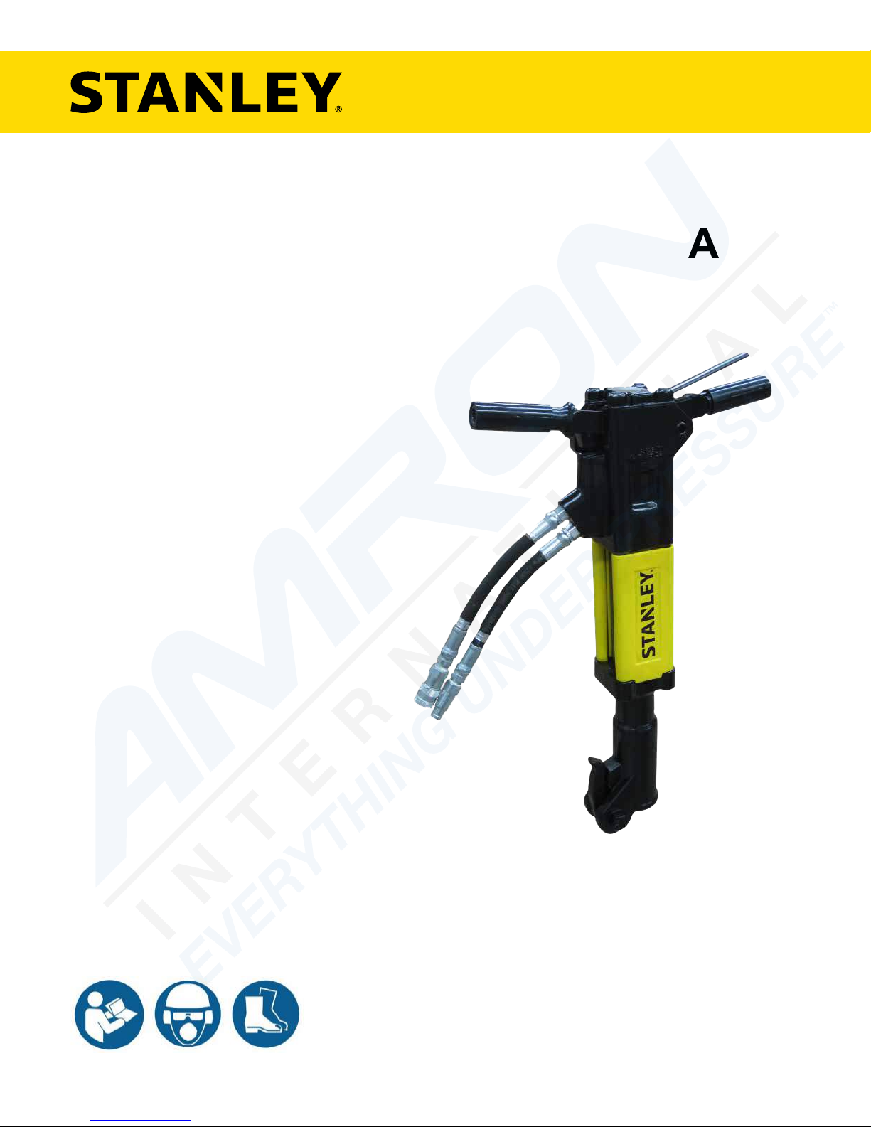
BR45
HYDRAULIC
BREAKER
USER MANUAL
Safety, Operation and Maintenance
© 2014 STANLEY Black & Decker, Inc.
New Britain, CT 06053
U.S.A.
62388 11/2017 Ver. 14
Page 2
DECLARATION OF CONFORMITY
ÜBEREINSTIMMUNGS-ERKLARUNG
DECLARATION DE CONFORMITE CEE
DECLARACION DE CONFORMIDAD
DICHIARAZIONE DI CONFORMITA
Hydraulic Tools
______________________________________________________________________
I, the undersigned:
Ich, der Unterzeichnende:
Je soussigné:
El abajo firmante:
lo sottoscritto:
Nuerenberg, David
Surname and First names/Familiennname und Vornamen/Nom et prénom/ Nombre y apellido/Cognome e nome
hereby declare that the equipment specified hereunder:
bestätige hiermit, daß erklaren Produkt genannten Werk oder Gerät:
déclare que l’équipement visé ci-dessous:
Por la presente declaro que el equipo se especifica a continuación:
Dichiaro che le apparecchiature specificate di seguito:
1. Category:
Hydraulic Hand Held Concrete Breaker
Kategorie:
Catégorie:
Categoria:
Categoria:
2. Make/Marke/Marque/Marca/Marca
STANLEY
3. Type/Typ/Type/Tipo/Tipo:
BR4514801, BR4516801, BR4516807, BR4516807A
BR4514801A, BR4556801, (BR45350 – For Underwater Use Only)
4. Serial number of equipment:
Seriennummer des Geräts:
Numéro de série de l’équipement:
Numero de serie del equipo:
Matricola dell´attrezzatura:
BR4514801 All
BR4514801A All
BR4516801 All
BR4516807 All
BR4516807A All
BR4556801 All
BR45350 Serial # 030612029 and above
(For Underwater Use Only)
5. Mass/Masse/Masse/Masa/Massa 23 kg
Has been manufactured in conformity with
Wurde hergestellt in Übereinstimmung mit
Est fabriqué conformément
Ha sido fabricado de acuerdo con
E’ stata costruita in conformitá con
Directive/Standards
Richtlinie/Standards
Directives/Normes
Directriz/Los Normas
Direttiva/Norme
No.
Nr
Numéro
No
n.
Approved body
Prüfung durch
Organisme agréé
Aprobado
Collaudato
ISO
Noise Directive
Machinery Directive
ISO
11148-4:2012
2000/14/EC:2005
3744:2010
2006/42/EC:2006
28927-10:2011
Self
AkustikNet (Notified body ID 1585)
Bagsvard Hovedgade 141, 2880 Bagsvard, Denmark
Certificate #863/2011/002 (Verification 2015-08-04) Valid: 12/31/2018
Self
Self
6. Special Provisions: None 7. Measurements: Measured Sound Power Level 105 LwA
Spezielle Bestimmungen: Messungen Guaranteed Sound Power Level 107 LwA
Dispositions particulières: Mesures Measured in accordance to Directive 2000/14/EC,
Provisiones especiales: Mediciones Annex III, Part B, No 10, 15 kg<m< 30 kg
Disposizioni speciali: Misurazioni
8. Representative in the Union: Patrick Vervier, Stanley Dubuis 17-19, rue Jules Berthonneau-BP 3406 41034 Blois Cedex, France.
Vertreter in der Union/Représentant dans l’union/Representante en la Union/Rappresentante presso l’Unione
Done at/Ort/Fait à/Dado en/Fatto a Stanley Infrastructure, Milwaukie, Oregon USA Date/Datum/le/Fecha/Data 8-4-2015
Signature/Unterschrift/Signature/Firma/Firma
Position/Position/Fonction/Cargo/Posizione North America Quality Manager
DECLARATION OF CONFORMITY
2 ► BR45 User Manual
Page 3
TABLE OF CONTENTS
SAFETY SYMBOLS ..................................................................................................................................................4
SAFETY PRECAUTIONS .......................................................................................................................................... 5
TOOL STICKERS & TAGS ........................................................................................................................................ 6
HOSE TYPES ............................................................................................................................................................7
HOSE RECOMMENDATIONS ..................................................................................................................................8
HTMA / EHTMA REQUIREMENTS ...........................................................................................................................9
OPERATION ............................................................................................................................................................ 10
TOOL PROTECTION & CARE ................................................................................................................................ 11
TROUBLESHOOTING ............................................................................................................................................12
CHARGING THE ACCUMULATOR .........................................................................................................................13
SPECIFICATIONS ................................................................................................................................................... 15
ACCESSORIES.......................................................................................................................................................16
PARTS ILLUSTRATION ..........................................................................................................................................18
PARTS LIST ............................................................................................................................................................19
BR45 ANTI-VIBRATION HANDLE PARTS ILLUSTRATION ...................................................................................20
BR45 ANTI-VIBRATION HANDLE PARTS LIST .....................................................................................................21
BREAKER FOOT ASSEMBLY 07489......................................................................................................................22
BREAKER FOOT ASSEMBLY 07510......................................................................................................................23
BREAKER FOOT ASSEMBLY 07694......................................................................................................................24
BREAKER FOOT ASSEMBLY 07899......................................................................................................................25
BREAKER FOOT ASSEMBLY 08081......................................................................................................................26
BREAKER FOOT ASSEMBLY 08154......................................................................................................................27
BREAKER FOOT ASSEMBLY 08856......................................................................................................................28
BREAKER FOOT ASSEMBLY 62334......................................................................................................................29
BREAKER FOOT ASSEMBLY 72931......................................................................................................................30
UNDERWATER TOOLS DEPTH GUIDELINE .........................................................................................................31
To ll out a product warranty validation form, and for information on your warranty,
visit www.stanleyinfrastructure.com and select the Company tab > Warranty.
Note: The warranty validation record must be submitted to validate the warranty.
SERVICING: This manual contains safety, operation and routine maintenance instructions. STANLEY Infrastructure
recommends that servicing of hydraulic tools, other than routine maintenance, must be performed by an authorized
and certied dealer. Please read the following warning.
SERIOUS INJURY OR DEATH COULD RESULT FROM THE IMPROPER REPAIR OR
SERVICE OF THIS TOOL.
REPAIRS AND / OR SERVICE TO THIS TOOL MUST ONLY BE DONE BY AN
AUTHORIZED AND CERTIFIED DEALER.
For the nearest certied dealer, call STANLEY Infrastructure at (503) 659-5660 and ask for a Customer Service Representative.
BR45 User Manual ◄ 3
Page 4
SAFETY SYMBOLS
Safety symbols and signal words, as shown below, are used to emphasize all operator, maintenance and repair
actions which, if not strictly followed, could result in a life-threatening situation, bodily injury or damage to equipment.
This is the safety alert symbol. It is used to alert you to potential personal injury
hazards. Obey all safety messages that follow this symbol to avoid possible
injury or death.
This safety alert and signal word indicates an imminently hazardous situation
which, if not avoided, will result in death or serious injury.
This safety alert and signal word indicates a potentially hazardous situation
which, if not avoided, could result in death or serious injury.
This safety alert and signal word indicates a potentially hazardous situation
which, if not avoided, could result in death or serious injury.
This signal word indicates a potentially hazardous situation which, if not avoided,
may result in property damage.
This signal word indicates a situation which, if not avoided, will result in damage
to the equipment.
This signal word indicates a situation which, if not avoided, may result in damage
to the equipment.
Always observe safety symbols. They are included for your safety and for the protection of the tool.
LOCAL SAFETY REGULATIONS
Enter any local safety regulations here. Keep these instructions in an area accessible to the operator and
maintenance personnel.
4 ► BR45 User Manual
Page 5
SAFETY PRECAUTIONS
Tool operators and maintenance personnel must always
comply with the precautions given in this manual and on
the stickers and tags attached to the tool and hose.
These precautions are given for your safety. Review
them carefully before operating the tool and before
performing general maintenance or repairs.
Supervising personnel should develop additional
precautions relating to the specic work area and local
safety regulations. Place the added precautions in the
space provided in this manual.
The BR45 Hydraulic Breaker will provide safe and
dependable service if operated in accordance with the
instructions given in this manual. Read and understand
this manual and any stickers and tags attached to the
tool and hoses before operation. Failure to do so could
result in personal injury or equipment damage.
• Operator must start in a work area without
bystanders. The operator must be familiar with all
prohibited work areas such as excessive slopes and
dangerous terrain conditions.
• Establish a training program for all operators to
ensure safe operation.
• Do not operate the tool unless thoroughly trained or
under the supervision of an instructor.
• Always wear safety equipment such as goggles,
gloves, ear protection, head protection, breathing
protection and safety shoes at all times when
operating the tool.
• Do not inspect, carry or clean the tool while the
hydraulic power source is connected. Accidental
engagement of the tool can cause serious injury.
• Supply hoses must have a minimum working
pressure rating of 2500 psi/175 bar.
• Be sure all hose connections are tight.
• The hydraulic circuit control valve must be in the
“OFF” position when coupling or uncoupling the tool.
Wipe all couplers clean before connecting. Use only
lint-free cloths. Failure to do so may result in damage
to the quick couplers and cause overheating of the
hydraulic system.
• Do not operate the tool at oil temperatures above
140 °F/60 °C. Operation at higher oil temperatures
can cause operator discomfort and may damage the
tool. Never contact the tool bit, the bit can get hot.
• Do not operate a damaged, improperly adjusted or
incompletely assembled tool.
• Do not weld, cut with an acetylene torch or hardface the tool bit.
• To avoid personal injury or equipment damage,
all tool repair, maintenance and service must only
be performed by authorized and properly trained
personnel.
• Do not exceed the rated limits of the tool or use the
tool for applications beyond its design capacity.
• Always keep critical tool markings, such as labels
and warning stickers, legible.
• Always replace parts with replacement parts
recommended by STANLEY.
• Check fastener tightness often and before each use
daily.
• Never operate the tool if you cannot be sure that
underground utilities are not present.
• Do not wear loose tting clothing when operating the
tool.
• Warning: Use of this tool on certain materials could
generate dust potentially containing a variety of
hazardous substances such as asbestos, silica or
lead. Inhalation of dust containing these or other
hazardous substances could result in serious
injury, cancer or death. Protect yourself and those
around you. Research and understand the materials
you are cutting. Follow correct safety procedures
and comply with all applicable national, state or
provisional health and safety regulations relating to
them, including, if appropriate arranging for the safe
disposal of the materials by a qualied person.
• Warning: Hydraulic uid under pressure could
cause skin injection injury. If you are injured by
hydraulic uid, get medical attention immediately.
• Keep all body parts away from the working tool.
• When handling material or the tool bit, wear your
Personal Protection Equipment (PPE).
• Be observant of the hydraulic hoses lying about the
work area. They can be a tripping hazard.
• Always de-energize the hydraulic system when
changing a tool bit.
• Never use the tool in an explosive atmosphere.
Sparks could ignite explosive gas.
• Use proper lifting techniques when handling the tool.
Get help from a co-worker and do not over-reach.
• Use proper protection from falling or ying debris
and keep bystanders at a safe distance.
• Do not exceed the rated ow and pressure. See
Specications in this manual for correct ow rate
and pressure rating. Rapid failure of the internal
seals may result.
BR45 User Manual ◄ 5
Page 6
TOOL STICKERS & TAGS
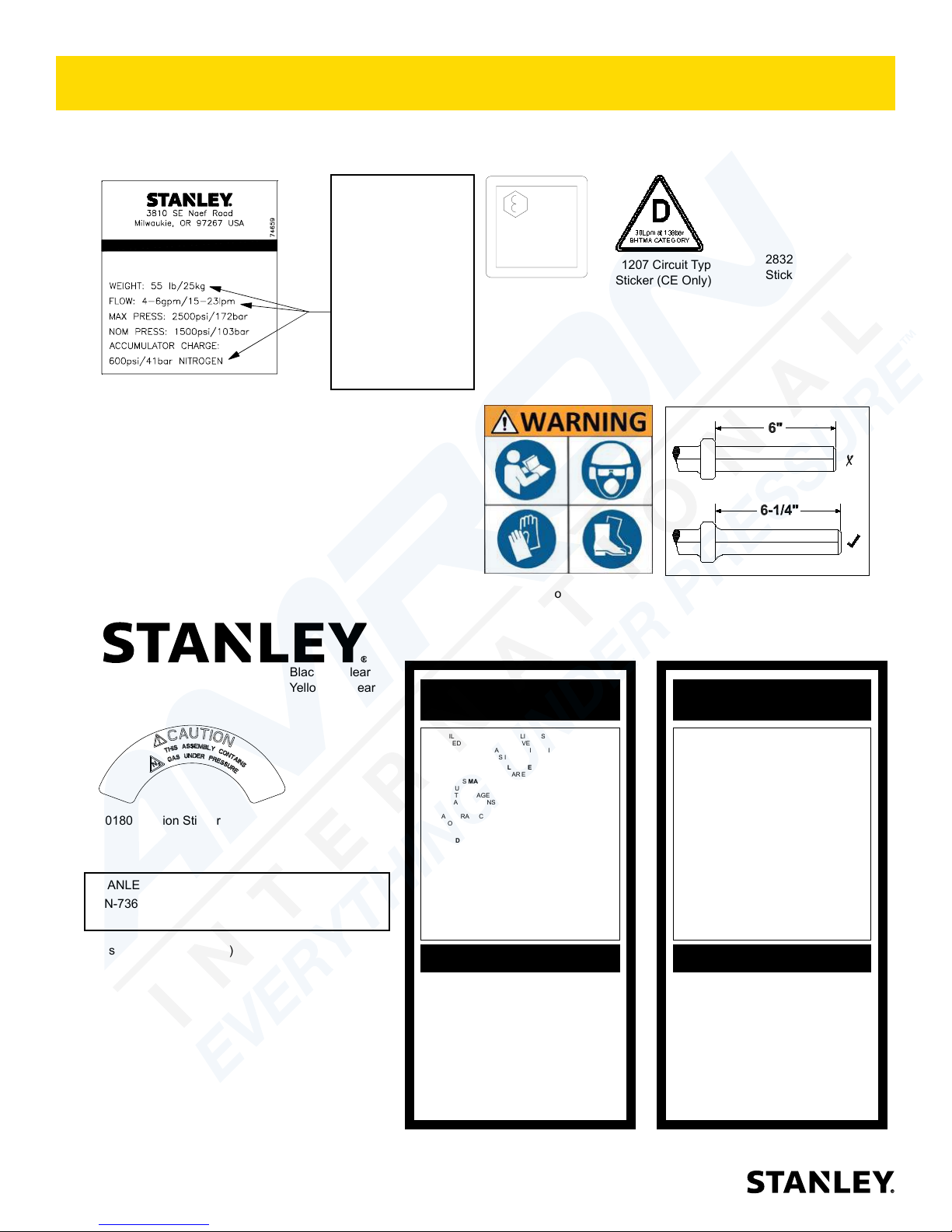
Please refer to the Parts Illustration for location of stickers.
BR45 BREAKER
74659 5-GPM Anti-Vib Name
Tag Sticker
74660 5-GPM T-Handle Name
Tag Sticker
74663 8-GPM Anti-Vib Name
Tag Sticker
74664 8-GPM T-Handle Name
Tag Sticker
74669 8-GPM T-Handle Name
Tag Sticker Under Water
These numbers
are for example
only and may
not relate to your
model of breaker,
see part numbers
below for name
tag stickers that
ts your model
breaker.
Lwa
107
58601 Sound Level
Sticker (CE Only)
28409 Composite
Sticker (CE Only)
11207 Circuit Type C
Sticker (CE Only)
11208 Hex Shank
Length Sticker
28322 CE
Sticker (CE Only)
74832 STANLEY Logo 5.5” x 1.1” Black on Clear
74770 STANLEY Logo 6.5” x 1.3” Yellow on Clear
10180 Caution Sticker
STANLEY Railroad Help Desk Sticker (Not Pictured)
P/N-73680
The safety tag (P/N 15875) at right is attached to
the tool when shipped from the factory. Read and
understand the safety instructions listed on this tag
before removal. We suggest you retain this tag and
attach it to the tool when not in use.
1. FAILURE TO USE HYDRAULIC HOSE LABELED AND CERTIFIED AS NON-CONDUCTIVE WHEN USING HYDRAULIC
TOOLS ON OR NEAR ELECTRICAL LINES MAY RESULT IN
DEATH OR SERIOUS INJURY.
BEFORE USING HOSE LABELED AND CERTIFIED AS NONCONDUCTIVE ON OR NEAR ELECTRIC LINES BE SURE THE
HOSE IS MAINTAINED AS NON-CONDUCTIVE. THE HOSE
SHOULD BE REGULARLY TESTED FOR ELECTRIC CURRENT LEAKAGE IN ACCORDANCE WITH YOUR SAFETY
DEPARTMENT INSTRUCTIONS.
2. A HYDRAULIC LEAK OR BURST MAY CAUSE OIL INJECTION INTO THE BODY OR CAUSE OTHER SEVERE
PERSONAL INJURY.
A. DO NOT EXCEED SPECIFIED FLOW AND PRESSURE
FOR THIS TOOL. EXCESS FLOW OR PRESSURE MAY
CAUSE A LEAK OR BURST.
B. DO NOT EXCEED RATED WORKING PRESSURE OF
HYDRAULIC HOSE USED WITH THIS TOOL. EXCESS
PRESSURE MAY CAUSE A LEAK OR BURST.
C. CHECK TOOL HOSE COUPLERS AND CONNECTORS
DAILY FOR LEAKS. DO NOT FEEL FOR LEAKS WITH
YOUR HANDS. CONTACT WITH A LEAK MAY RESULT
IN SEVERE PERSONAL INJURY.
IMPORTANT
READ OPERATION MANUAL AND
SAFETY INSTRUCTIONS FOR THIS
TOOL BEFORE USING IT.
USE ONLY PARTS AND REPAIR
PROCEDURES APPROVED BY
STANLEY AND DESCRIBED IN THE
OPERATION MANUAL.
TAG TO BE REMOVED ONLY BY
TOOL OPERATOR.
SEE OTHER SIDE
DANGERDANGER
D. DO NOT LIFT OR CARRY TOOL BY THE HOSES. DO
NOT ABUSE HOSE. DO NOT USE KINKED, TORN OR
DAMAGED HOSE.
3. MAKE SURE HYDRAULIC HOSES ARE PROPERLY CONNECTED TO THE TOOL BEFORE PRESSURING SYSTEM.
SYSTEM PRESSURE HOSE MUST ALWAYS BE CONNECTED TO TOOL “IN” PORT. SYSTEM RETURN HOSE
MUST ALWAYS BE CONNECTED TO TOOL “OUT” PORT.
REVERSING CONNECTIONS MAY CAUSE REVERSE
TOOL OPERATION WHICH CAN RESULT IN SEVERE
PERSONAL INJURY.
4. DO NOT CONNECT OPEN-CENTER TOOLS TO CLOSEDCENTER HYDRAULIC SYSTEMS. THIS MAY RESULT IN
LOSS OF OTHER HYDRAULIC FUNCTIONS POWERED BY
THE SAME SYSTEM AND/OR SEVERE PERSONAL INJURY.
5. BYSTANDERS MAY BE INJURED IN YOUR WORK AREA.
KEEP BYSTANDERS CLEAR OF YOUR WORK AREA.
6. WEAR HEARING, EYE, FOOT, HAND AND HEAD PROTECTION.
7. TO AVOID PERSONAL INJURY OR EQUIPMENT DAMAGE,
ALL TOOL REPAIR MAINTENANCE AND SERVICE MUST
ONLY BE PERFORMED BY AUTHORIZED AND PROPERLY
TRAINED PERSONNEL.
IMPORTANT
READ OPERATION MANUAL AND
SAFETY INSTRUCTIONS FOR THIS
TOOL BEFORE USING IT.
USE ONLY PARTS AND REPAIR
PROCEDURES APPROVED BY
STANLEY AND DESCRIBED IN THE
OPERATION MANUAL.
TAG TO BE REMOVED ONLY BY
TOOL OPERATOR.
SEE OTHER SIDE
6 ► BR45 User Manual
SAFETY TAG P/N 15875 (Shown smaller then actual size)
Page 7
HOSE TYPES
The rated working pressure of the hydraulic hose must be equal to or higher than the relief valve setting on the
hydraulic system. There are three types of hydraulic hose that meet this requirement and are authorized for use with
STANLEY hydraulic tools. They are:
Certied non-conductive — constructed of thermoplastic or synthetic rubber inner tube, synthetic ber braid
reinforcement, and weather resistant thermoplastic or synthetic rubber cover. Hose labeled certied non-
conductive is the only hose authorized for use near electrical conductors.
Wire-braided (conductive) — constructed of synthetic rubber inner tube, single or double wire braid
reinforcement, and weather resistant synthetic rubber cover. This hose is conductive and must never be used
near electrical conductors.
Fabric-braided (not certied or labeled non-conductive) — constructed of thermoplastic or synthetic rubber
inner tube, synthetic ber braid reinforcement, and weather resistant thermoplastic or synthetic rubber cover.
This hose is not certied non-conductive and must never be used near electrical conductors.
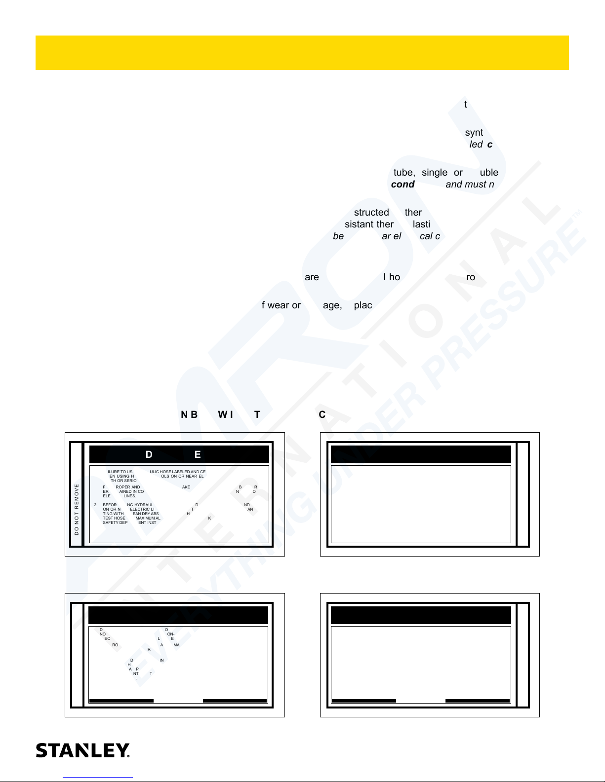
HOSE SAFETY TAGS
To help ensure your safety, the following DANGER tags are attached to all hose purchased from STANLEY. DO
NOT REMOVE THESE TAGS.
If the information on a tag is illegible because of wear or damage, replace the tag immediately. A new tag may be
obtained from your STANLEY Distributor.
THE TAG SHOWN BELOW IS ATTACHED TO “CERTIFIED NON-CONDUCTIVE” HOSE
DANGER
1. FAILURE TO USE HYDRAULIC HOSE LABELED AND CERTIFIED AS NON-CONDUCTIVE
WHEN USING HYDRAULIC TOOLS ON OR NEAR ELECTRIC LINES MAY RESULT IN
DEATH OR SERIOUS INJURY.
FOR PROPER AND SAFE OPERATION MAKE SURE THAT YOU HAVE BEEN PROPERLY TRAINED IN CORRECT PROCEDURES REQUIRED FOR WORK ON OR AROUND
ELECTRIC LINES.
2. BEFORE USING HYDRAULIC HOSE LABELED AND CERTIFIED AS NON-CONDUCTIVE
ON OR NEAR ELECTRIC LINES. WIPE THE ENTIRE LENGTH OF THE HOSE AND FITTING WITH A CLEAN DRY ABSORBENT CLOTH TO REMOVE DIRT AND MOISTURE AND
TEST HOSE FOR MAXIMUM ALLOWABLE CURRENT LEAKAGE IN ACCORDANCE WITH
SAFETY DEPARTMENT INSTRUCTIONS.
DO NOT REMOVE THIS TAG
SEE OTHER SIDE
SIDE 1
3. DO NOT EXCEED HOSE WORKING PRESSURE OR ABUSE HOSE. IMPROPER USE
OR HANDLING OF HOSE COULD RESULT IN BURST OR OTHER HOSE FAILURE.
KEEP HOSE AS FAR AWAY AS POSSIBLE FROM BODY AND DO NOT PERMIT DIRECT
CONTACT DURING USE. CONTACT AT THE BURST CAN CAUSE BODILY INJECTION
AND SEVERE PERSONAL INJURY.
4. HANDLE AND ROUTE HOSE CAREFULLY TO AVOID KINKING, ABRASION, CUTTING, OR
CONTACT WITH HIGH TEMPERATURE SURFACES. DO NOT USE IF KINKED. DO NOT
USE HOSE TO PULL OR LIFT TOOLS, POWER UNITS, ETC.
5. CHECK ENTIRE HOSE FOR CUTS CRACKS LEAKS ABRASIONS, BULGES, OR DAMAGE TO COUPLINGS IF ANY OF THESE CONDITIONS EXIST, REPLACE THE HOSE
IMMEDIATELY. NEVER USE TAPE OR ANY DEVICE TO ATTEMPT TO MEND THE HOSE.
6. AFTER EACH USE STORE IN A CLEAN DRY AREA.
(Shown smaller than actual size)
DANGER
DANGER
SEE OTHER SIDE
SIDE 2
THE TAG SHOWN BELOW IS ATTACHED TO “CONDUCTIVE” HOSE.
DANGER
DANGER
1. DO NOT USE THIS HYDRAULIC HOSE ON OR NEAR ELECTRIC LINES. THIS HOSE IS
NOT LABELED OR CERTIFIED AS NON-CONDUCTIVE. USING THIS HOSE ON OR NEAR
ELECTRICAL LINES MAY RESULT IN DEATH OR SERIOUS INJURY.
2. FOR PROPER AND SAFE OPERATION MAKE SURE THAT YOU HAVE BEEN PROPERLY
TRAINED IN CORRECT PROCEDURES REQUIRED FOR WORK ON OR AROUND ELECTRIC LINES.
3. DO NOT EXCEED HOSE WORKING PRESSURE OR ABUSE HOSE. IMPROPER USE OR
HANDLING OF HOSE COULD RESULT IN BURST OR OTHER HOSE FAILURE. KEEP HOSE
AS FAR AWAY AS POSSIBLE FROM BODY AND DO NOT PERMIT DIRECT CONTACT
DURING USE. CONTACT AT THE BURST CAN CAUSE BODILY INJECTION AND SEVERE
PERSONAL INJURY.
4. HANDLE AND ROUTE HOSE CAREFULLY TO AVOID KINKING, CUTTING, OR CONTACT
WITH HIGH TEMPERATURE SURFACES. DO NOT USE IF KINKED. DO NOT USE HOSE TO
PULL OR LIFT TOOLS, POWER UNITS, ETC.
DO NOT REMOVE THIS TAG
SEE OTHER SIDE
SIDE 1
5. CHECK ENTIRE HOSE FOR CUTS CRACKS LEAKS ABRASIONS, BULGES, OR DAMAGE TO
COUPLINGS IF ANY OF THESE CONDITIONS EXIST, REPLACE THE HOSE IMMEDIATELY.
NEVER USE TAPE OR ANY DEVICE TO ATTEMPT TO MEND THE HOSE.
6. AFTER EACH USE STORE IN A CLEAN DRY AREA.
(Shown smaller than actual size)
DANGER
SEE OTHER SIDE
SIDE 2
DO NOT REMOVE THIS TAG
DO NOT REMOVE THIS TAG
BR45 User Manual ◄ 7
Page 8
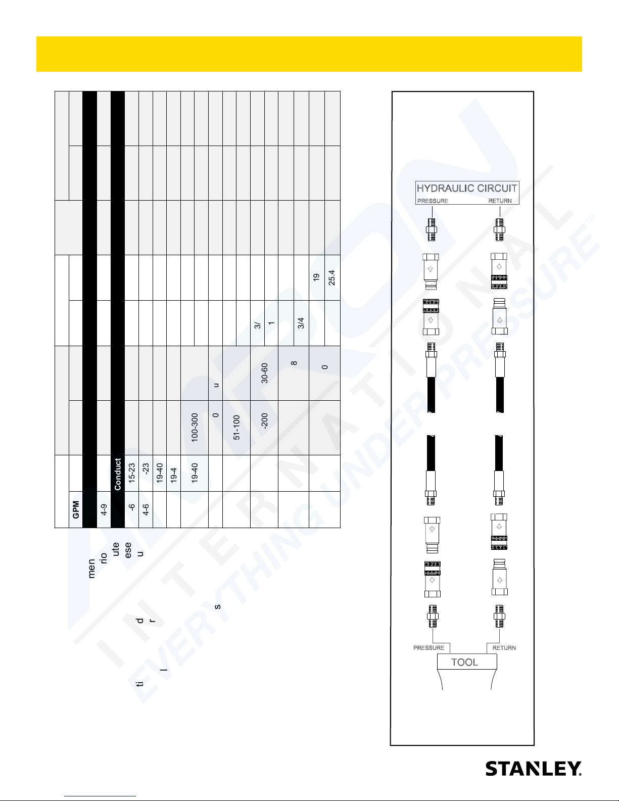
HOSE RECOMMENDATIONS
Min. Working Pressure
USE
Press/Return)
(
Certied Non-Conductive Hose - Fiber Braid - for Utility Bucket Trucks
5/8 16 Pressure 2500 175
3/4 19 Return 2500 175
5/8 16 Pressure 2500 175
3/4 19 Return 2500 175
3/4 19 Pressure 2500 175
1 25.4 Return 2500 175
5/8 16 Pressure 2500 175
3/4 19 Return 2500 175
2500 175
1 25.4 Return 2500 175
3/4 19 Pressure
PRESSURE
<<< FLOW
RETURN
FLOW >>>
Conductive Hose - Wire Braid or Fiber Braid -DO NOT USE NEAR ELECTRICAL CONDUCTORS
Oil Flow Hose Lengths Inside Diameter
Tool to Hydraulic Circuit Hose
4-9 15-34 up to 10 up to 3 3/8 10 Both 2250 155
4-6 15-23 up to 25 up to 7.5 3/8 10 Both 2500 175
GPM LPM FEET METERS INCH MM PSI BAR
Recommendations
The chart to the right shows recommended
minimum hose diameters for various
4-6 15-23 26-100 7.5-30 1/2 13 Both 2500 175
5-10.5 19-40 up to 50 up to 15 1/2 13 Both 2500 175
hose lengths based on gallons per minute
(GPM)/liters per minute (LPM). These
recommendations are intended to keep return
line pressure (back pressure) to a minimum
acceptable level to ensure maximum tool
8 ► BR45 User Manual
5-10.5 19-40 51-100 15-30 5/8 16 Both 2500 175
performance.
10-13 38-49 up to 50 up to 15 5/8 16 Both 2500 175
5-10.5 19-40 100-300 30-90
This chart is intended to be used for hydraulic
tool applications only based on STANLEY tool
operating requirements and should not be
10-13 38-49 51-100 15-30
10-13 38-49 100-200 30-60
13-16 49-60 up to 25 up to 8
used for any other applications.
All hydraulic hose must have at least a
rated minimum working pressure equal to
the maximum hydraulic system relief valve
setting.
13-16 49-60 26-100 8-30
All hydraulic hose must meet or exceed
specications as set forth by SAE J517.
Figure 1. Typical Hose Connections
Page 9
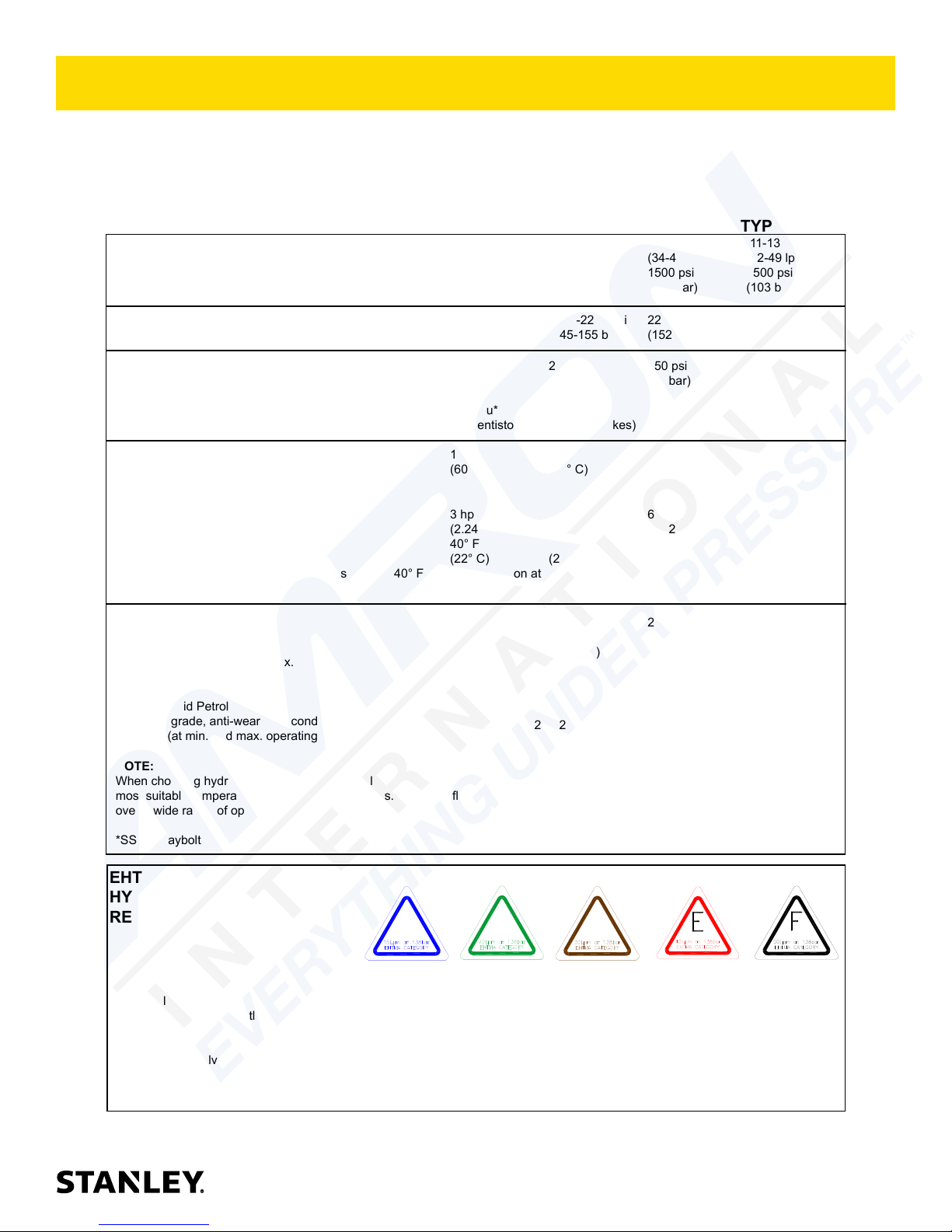
250 psi 250 psi 250 psi 250 psi
(17 bar) (17 bar) (17 bar) (17 bar)
400 ssu* 400 ssu* 400 ssu* 400 ssu*
(60° C) (60° C) (60° C) (60° C)
(22° C) (22° C) (22° C) (22° C)
30 gpm 30 gpm 30 gpm 30 gpm
HTMA / EHTMA REQUIREMENTS
HTMA / EHTMA REQUIREMENTS
HTMA
HYDRAULIC SYSTEM REQUIREMENTS
Flow Range
Nominal Operating Pressure
(at the power supply outlet)
System relief valve setting
(at the power supply outlet)
Maximum back pressure
(at tool end of the return hose)
Measured at a max. uid viscosity of:
(at min. operating temperature)
Temperature: Suf cient heat rejection
capacity to limit max. uid temperature to:
(at max. expected ambient temperature)
Min. cooling capacity at a temperature
difference of between ambient and uid
temps
NOTE:
Do not operate the tool at oil temperatures above 140° F (60° C). Operation at higher temperatures can cause operator
discomfort at the tool.
Filter
Min. full- ow ltration
Sized for ow of at least:
(For cold temp. startup and max.
dirt-holding capacity)
4-6 gpm 7-9 gpm 9-10.5 gpm 11-13 gpm
(15-23 lpm) (26-34 lpm) (34-40 lpm) (42-49 lpm)
1500 psi 1500 psi 1500 psi 1500 psi
(103 bar) (103 bar) (103 bar) (103 bar)
2100-2250 psi 2100-2250 psi 2200-2300 psi 2100-2250 psi
(145-155 bar) (145-155 bar) (152-159 bar) (145-155 bar)
(82 centistokes) (82 centistokes) (82 centistokes) (82 centistokes)
140° F 140° F 140° F 140° F
3 hp 5 hp 6 hp 7 hp
(2.24 kW) (3.73 kW) (5.22 kW) (4.47 kW)
40° F 40° F 40° F 40° F
25 microns 25 microns 25 microns 25 microns
(114 lpm) (114 lpm) (114 lpm) (114 lpm)
TYPE I TYPE II
TOOL TYPE
TYPE RR
TYPE III
Hydraulic uid Petroleum based
(premium grade, anti-wear, non-conductive)
Viscosity (at min. and max. operating temps)
NOTE:
When choosing hydraulic uid, the expected oil temperature extremes that will be experienced in service determine the
most suitable temperature viscosity characteristics. Hydraulic uids with a viscosity index over 140 will meet the requirements
over a wide range of operating temperatures.
*SSU = Saybolt Seconds Universal
EHTMA
100-400 ssu* 100-400 ssu* 100-400 ssu* 100-400 ssu*
(20-82 centistokes)
CLASSIFICATION
HYDRAULIC SYSTEM
REQUIREMENTS
Flow Range
Nominal Operating Pressure
(at the power supply outlet)
System relief valve setting
(at the power supply outlet)
NOTE: These are general hydraulic system requirements. See tool speci cation page for tool speci c requirements
B
3.5-4.3 gpm 4.7-5.8 gpm 7.1-8.7 gpm 9.5-11.6 gpm 11.8-14.5 gpm
(13.5-16.5 lpm) (18-22 lpm) (27-33 lpm) (36-44 lpm) (45-55 lpm)
1870 psi 1500 psi 1500 psi 1500 psi 1500 psi
(129 bar) (103 bar) (103 bar) (103 bar) (103 bar)
2495 psi 2000 psi 2000 psi 2000 psi 2000 psi
(172 bar) (138 bar) (138 bar) (138 bar) (138 bar)
C
D
BR45 User Manual ◄ 9
Page 10
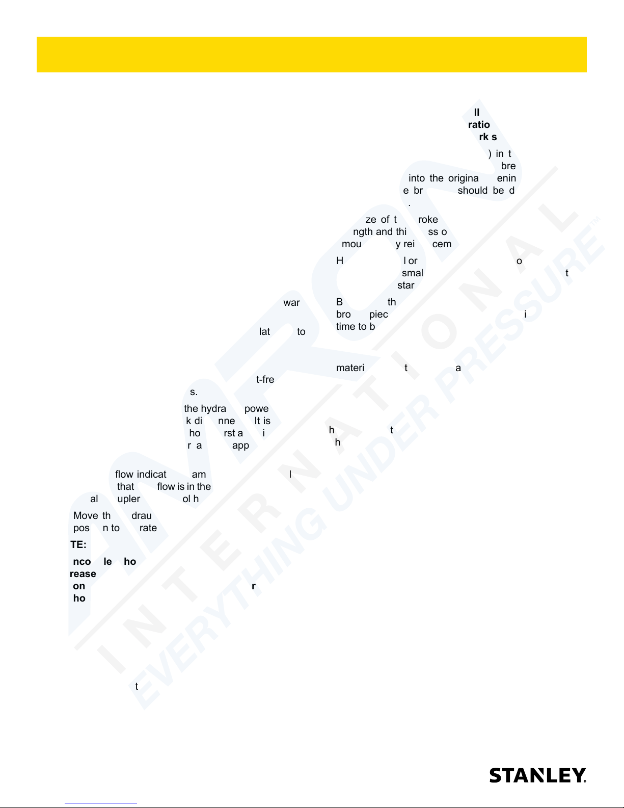
OPERATION
The recommended hose size is .500 inch/12 mm I.D. up
to 50 ft/15 m long and .625 inch/16 mm I.D. minimum up
to 100 ft/30 m.
PRE-OPERATION PROCEDURES
CHECK POWER SOURCE
1. Using a calibrated owmeter and pressure gauge,
check that the hydraulic power source develops a
ow of 7–9 GPM/26–34 LPM at 1500–2000 psi/105–
140 bar or 5–6 GPM /18–22 LPM at 1500–2000 psi
/105–140 bar.
2. Make certain the hydraulic power source is equipped
with a relief valve set to open at 2250 psi/155 bar
maximum.
INSTALL TOOL BIT
1. Rotate the latch on the breaker foot downward
(pointing away from the tool).
2. Insert the tool bit into the foot and pull the latch up to
lock the tool bit in place.
CONNECT HOSES
1. Wipe all hose couplers with a clean, lint-free cloth
before making connections.
2. Connect the hoses from the hydraulic power source
to the tool ttings or quick disconnects. It is a good
practice to connect return hoses rst and disconnect
them last to minimize or avoid trapped pressure
within the tool.
3. Observe ow indicators stamped on hose couplers
to ensure that uid ow is in the proper direction. The
female coupler on the tool hose is the inlet coupler.
4. Move the hydraulic circuit control valve to the ON
position to operate the tool.
NOTE:
If uncoupled hoses are left in the sun, pressure
increase within the hoses may make them difcult
to connect. When possible, connect the free ends of
the hoses together.
NOTE:
Partially depressing the trigger allows the tool to run
at slow speed. Slow-speed operation permits easier
starting of the tool bit into the work surface.
5. To start, break an opening (hole) in the center of
the surface. After making a hole, break portions
of the material into the original opening. For best
productivity, the breaking should be done around
the original hole.
The size of the broken material will vary with the
strength and thickness of the base material and the
amount of any reinforcement wire or rebar.
Harder material or more reinforcing wire or rebar will
require taking smaller bites. To determine the most
effective bite, start with 2 in. / 50 mm or smaller bites.
Bites can then be gradually increased until the
broken piece becomes too large, requiring increased
time to break off the piece.
Sticking of the tool bit occurs when too large a bite
is being taken and the tool bit hammers into the
material without the material fracturing. This causes
the tool bit to become trapped in the surrounding
material.
COLD WEATHER OPERATION
If the breaker is to be used during cold weather, preheat
the hydraulic uid at low engine speed. When using the
normally recommended uid, uid temperature should
be at or above 50 °F/10 °C (400 ssu/82 centistokes)
before use.
Damage to the hydraulic system or breaker can result
from use with uid that is too viscous or thick.
OPERATION PROCEDURES
1. Observe all safety precautions.
2. Install the appropriate tool bit for the job.
3. Place the bit rmly on the surface to be broken.
4. Squeeze the trigger to start the breaker. Adequate
down pressure is very important. When the tool bit
breaks through the obstruction or becomes bound,
release the trigger and reposition the tool bit.
10 ► BR45 User Manual
Page 11
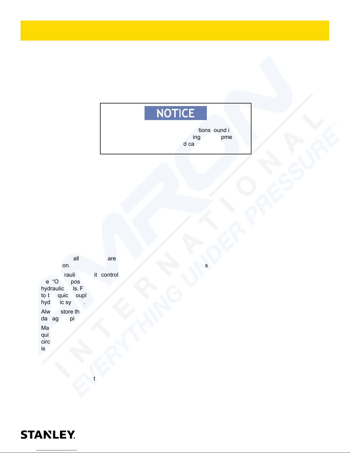
TOOL PROTECTION & CARE
In addition to the Safety Precautions found in
this manual, observe the following for equipment
protection and care.
• Make sure all couplers are wiped clean before
connection.
• The hydraulic circuit control valve must be in
the “OFF” position when coupling or uncoupling
hydraulic tools. Failure to do so may result in damage
to the quick couplers and cause overheating of the
hydraulic system.
• Always store the tool in a clean dry space, safe from
damage or pilferage.
• Make sure the circuit PRESSURE hose (with male
quick disconnect) is connected to the “IN” port. The
circuit RETURN hose (with female quick disconnect)
is connected to the opposite port. Do not reverse
circuit ow. This can cause damage to internal seals.
• Always replace hoses, couplings and other parts
with replacement parts recommended by STANLEY.
Supply hoses must have a minimum working
pressure rating of 2500 psi/172 bar.
• Do not exceed the rated ow and pressure. See
Specications in this manual for correct ow rate
and pressure rating. Rapid failure of the internal
seals may result.
• Always keep critical tool markings, such as warning
stickers and tags legible.
• Do not force a small breaker to do the job of a large
breaker.
• Keep tool bit sharp for maximum breaker
performance. Make sure that tool bits are not
chipped or rounded on the striking end.
• Never operate a breaker without a tool bit or without
holding it against the work surface. This puts
excessive strain on the breaker foot.
• Tool repair should be performed by experienced
personnel only.
• Make certain that the recommended relief valves
are installed in the pressure side of the system.
• Do not use the tool for applications for which it was
not intended.
BR45 User Manual ◄ 11
Page 12
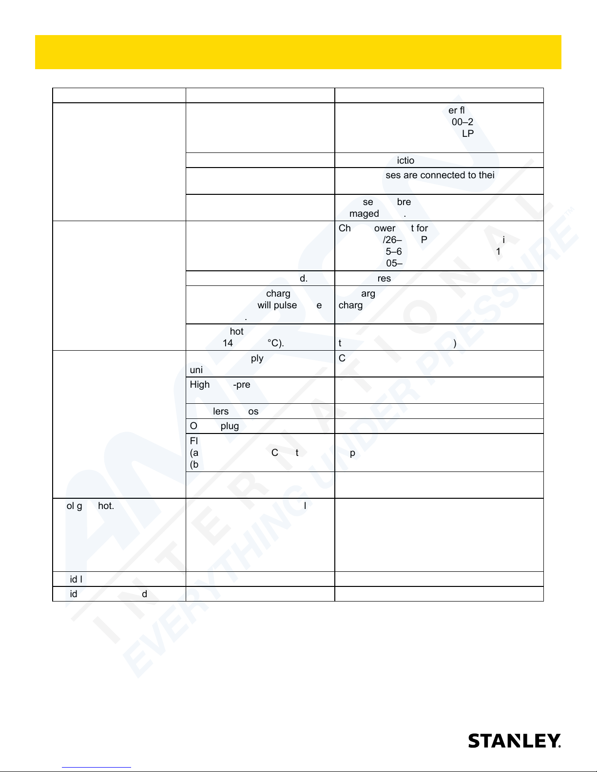
TROUBLESHOOTING
PROBLEM CAUSE REMEDY
Tool does not run. Power unit not functioning. Check power unit for power ow and pressure
(7–9 GPM/26–34 LPM, 1500–2000 psi/105–
140 bar or 5–6 GPM /18–22 LPM at 1500–
2000 psi /105–140 bar.
Couplers or hoses blocked. Remove restriction.
Pressure and return line hoses
reversed at ports.
Mechanical failure of piston or
automatic valve.
Tool does not hit effectively. Power unit not functioning. Check power unit for power ow and pressure
Couplers or hoses blocked. Remove restriction.
Low accumulator charge
(pressure hose will pulse more
than normal).
Fluid too hot
(above 140 °F/60 °C).
Tool operates slow. Low GPM supply from power
unit.
High back-pressure. Check hydraulic system for excessive back-
Couplers or hoses blocked. Remove restriction.
Orice plug blocked. Remove restriction.
Fluid too hot
(above 140 °F/60 °C) or too cold
(below 60 °F/16 °C).
Relief valve set too low. Adjust relief valve to 2100–2250 psi/145–155
Tool gets hot. Hot uid going through tool. Check power unit. Be sure ow rate is not too
Fluid leakage on tool bit. Lower piston seal failure. Replace seal.
Fluid leakage around trigger. Valve spool seal failure. Replace seals.
Be sure hoses are connected to their proper
ports.
Disassemble breaker and inspect for
damaged parts.
(7–9 GPM/26–34 LPM, 1500–2000 psi/105–
140 bar or 5–6 GPM /18–22 LPM at 1500–
2000 psi /105–140 bar.
Recharge accumulator. Replace diaphragm if
charge loss continues.
Provide cooler to maintain proper uid
temperature (130 °F/55 °C).
Check power unit for proper ow (7–9
GPM/26–34 LPM) or 5–6 GPM /18–22 LPM.
pressure (over 200 psi/14 bar).
Check power unit for proper uid temperature.
Bypass cooler to warm the uid or provide
cooler to maintain proper temperature.
bar.
high causing part of the uid to go through the
relief valve. Provide cooler to maintain proper
uid temperature (140 °F/60 °C max).
Check the relief valve setting.
Eliminate ow control devices.
12 ► BR45 User Manual
Page 13
CHARGING THE ACCUMULATOR
ACCUMULATOR TESTING
PROCEDURE
To check or charge the accumulator the following
equipment is required.
• 31254 Charge Kit, which includes the following:
– Accumulator Tester (Part Number 02835).
– Charging Assembly (P/N 15304) (15304
includes a liquid lled gauge with snub valve,
hose and ttings).
• NITROGEN bottle with an 800 psi/55 bar minimum
charge.(Not included in 31254 kit)
This assembly contains nitrogen under pressure
1.
Remove the plug from the handle or handle pivot.
2. Holding the chuck end of Accumulator Tester (P/N
02835) turn the gauge fully counterclockwise to
ensure that the stem inside the chuck is completely
retracted.
3. Thread the tester onto the accumulator charging
valve. Do not advance the gauge-end into the
chuck-end. Turn as a unit. Seat the chuck on the
accumulator charging valve and hand tighten only.
4. Advance the valve stem of the tester by turning the
gauge-end clockwise until a pressure is read on the
gauge (charge pressure should be 500-700 psi/3448 bar).
5. If pressure is OK unscrew the gauge-end from the
chuck to retract the stem, then unscrew the entire
tester assembly from the accumulator charging
valve. If pressure is low, charge the accumulator as
described in the following paragraph.
6. Install the plug.
ACCUMULATOR CHARGING
1. Perform steps 1 through 4 of the accumulator testing
procedure.
2. Connect the chuck of the charging assembly to
the charging valve on the accumulator tester or, if
preferred, remove the tester from the charging valve
and connect the charging assembly chuck directly to
the charging valve.
3. Adjust the snub valve to a charging pressure of 600
psi/42 bar.
NOTE:
While watching the pressure gauge, open snub valve
slowly until it reaches the proper charge pressure
(600-700 psi).
NOTE:
It may be necessary to set the gauge at 650-700
psi/45-48 bar to overcome any pressure drop
through the charging system.
4. When the accumulator is fully charged close the
snub valve on the charging assembly hose and
remove the charging assembly chuck from the
accumulator tester or tool charging valve.
5. If the accumulator tester has been used, be sure to
turn the gauge-end fully counterclockwise before
removing the tester from the charging valve of the
tool. Install the valve cap.
UNDERWATER MODEL
PREVENTATIVE MAINTENANCE
After each use, the movable portions of the tool that
were exposed to water should be ushed with a water
displacing oil such as WD40™. Remove any remaining
water and debris as follows:
1. Turn the tool upside down (without the tool bit) and
spray oil through the drive hex and side holes in the
breaker foot assembly to displace any remaining
water in the lower piston cavity.
2. Spray oil into the On/Off valve trigger slot area.
3. Dip or spray the entire tool.
4. Cycle the tool hydraulically several times before
storing away.
BR45 User Manual ◄ 13
Page 14
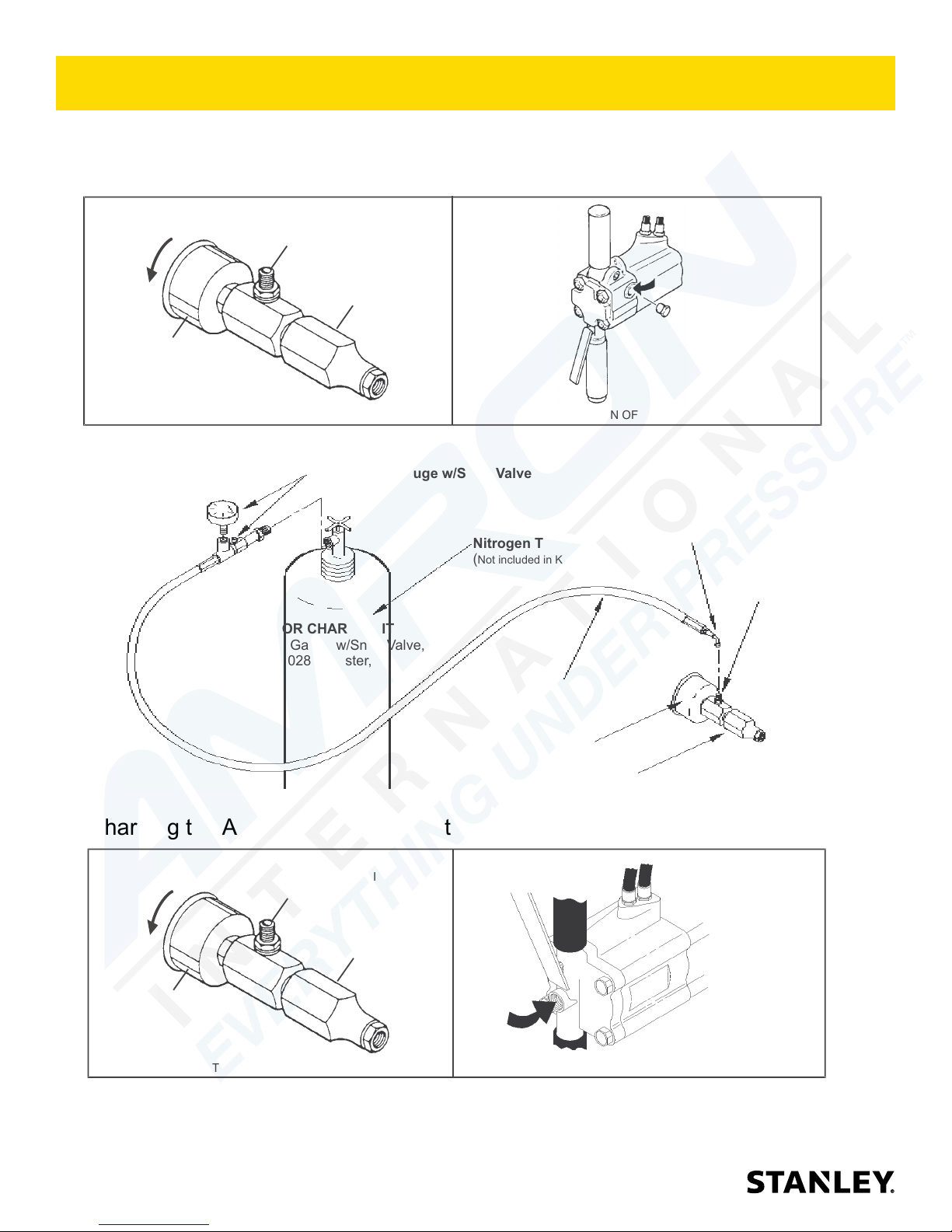
GAUGE
CHUCK
TESTER CHARGING
VALVE
CW
ACCUMULATOR TESTER(P/N 02835 )
Figure 2
LOCATION OF CHARGING VALV E
GAUGE
CHUCK
TESTER CHARGING
VALVE
CW
ACCUMULATOR TESTER(P/N 02835 )
Figure 2
LOCATION OF CHARGING VALV E
LiquidFilled Gauge w/Snub Valve
NitrogenTank
()
Not included in Kit
Gauge
Hose
Chuck
ChargeFitting
ChargingValve
31254 ACCUMULATOR CHARGE KIT
Includes: Liquid Filled Gauge w/Snub Valve,
Hose, Charge Fitting, 02835 Tester, and Box
(not pictured)
02835 TESTER
Charging the Accumulator (45 with Anti-Vibration Handles)BR
Charging the Accumulator (45 with T-Handles)BR
CHARGING THE ACCUMULATOR
14 ► BR45 User Manual
Figure 2. Charging the Accumulator
Page 15
SPECIFICATIONS
Pressure Range.............................................................................................................. 1500–2000 psi/105–140 bar
Flow Range ............................................................................................................................ 7–9 GPM / 26–34 LPM
4–6 GPM /15–22 LPM
Nominal Flow .....................................................................................................8 GPM / 30 LPM or 5 GPM / 19 LPM
Maximum Back Pressure......................................................................................................................250 Psi/17 bar
Couplers ......................................................................................................................................... HTMA Flush Face
Connect Size & Type ......................................................................................................3/8 in. Male Pipe Hose Ends
Weight ....................................................................................................................................T-Handle 51 lbs / 23 kg
Anti-Vibration Handle 55 lbs / 25 kg
Overall Length .....................................................................................................................T-Handle 25.5 in. / 65 cm
Anti-Vibration Handle 28.25 in. / 72 cm
Overall Width at Handles ........................................................................................................T-Handle 14 in. / 35 cm
Anti-Vibration Handle 17.5 in. / 44.5 cm
Max. Fluid Temperature ........................................................................................................................ 140 °F / 60 °C
System Type ...........................................................................................................................Open or Closed Center
Port Size .................................................................................................................................................SAE 8 O-ring
HTMA/EHTMA Category ..................................................................................................................................Type 2
Nominal Pressure ............................................................................................................................. 1500 psi/103 bar
Max Pressure ................................................................................................................................... 2500 psi/138 bar
Max Relief Pressure ......................................................................................................................... 2150 psi/148 bar
BR45 ANTI-VIBE SOUND AND VIBRATION DECLARATION
Test conducted on BR4516801,operated at standard 8 GPM input
Measured A-weighted sound power level, Lwa (ref. 1pW) in decibels .......................................................... 105 dBA
Uncertainty, Kwa, in decibels .......................................................................................................................... 1.7 dBA
Guaranteed sound power level...................................................................................................................... 107 dBA
Measured A-weighted sound pressure level, Lpa (ref. 20 µPa) at operator's position, in decibels ................. 98 dBA
Uncertainty, Kpa, in decibels ............................................................................................................................. 3 dBA
Values determined according to noise test code given in ISO 15744, using the basic standard ISO3744
Test conducted by independent notied body to comply with 2000/14/EC:2005 requirements.
NOTE: The sum of a measured noise emission value and its associated uncertainty represents an upper
boundary of the range of values which is likely to occur in measurements.
Declared vibration emission value in accordance with EN 12096 ...............................................................................
Measured vibration emission value: 3-Axis ................................................................................................ 5.8 m/sec²
Uncertainty: K ............................................................................................................................................. 0.8 m/sec²
Measured vibration emission value: 3-Axis with uncertainty ...................................................................... 6.6 m/sec²
Measured vibration emission value: Z-Axis ................................................................................................ 3.6 m/sec²
Uncertainty: K ............................................................................................................................................. 0.6 m/sec²
Measured vibration emission value: Z-Axis with uncertainty ...................................................................... 4.2 m/sec²
Values determined according to ISO 28927-10:2011
BR45 T-HANDLE VIBRATION DECLARATION
Declared vibration emission value in accordance with EN 12096
Measured vibration emission value: 3-Axis .............................................................................................. 17.6 m/sec²
Uncertainty: K ............................................................................................................................................. 1.2 m/sec²
Measured vibration emission value: 3-Axis with uncertainty .................................................................... 18.8 m/sec²
Values determined according to ISO 28927-10:2011
...............................................................................
BR45 User Manual ◄ 15
Page 16

ACCESSORIES
7/8 IN. HEX × 3-1/4 IN. SHANK
Clay Spade 16 in./40.6 cm U/C 7/8” Hex............................................................................................................02328
3 in./76 mm Wide Chisel 14 in./35.6 cm U/C 7/8” Hex.......................................................................................02330
Asphalt Cutter 5 in./12.7 cm Wide Blade × 11 in./27.9 cm U/C 7/8” Hex............................................................02341
Moil Point 18 in./45.7 cm U/C 7/8” Hex...............................................................................................................04401
Moil Point 14 in./35.6 cm U/C 7/8” Hex Heavy Duty............................................................................................04961
Rod Driver 3/4 in./19 mm Cup - 7/8” Hex............................................................................................................05255
1 IN. HEX × 4-1/4 IN. SHANK
Moil Point – 14 in. Long UC ............................................................................................................................... 07702
Narrow Chisel Point – 14 in. Long UC ............................................................................................................... 07703
3-inch Chisel – 14 in. Long UC .......................................................................................................................... 07704
Clay Spade – 5-1/2 in. Blade ............................................................................................................................. 07705
Asphalt Wedge – 3 in. Wide ..............................................................................................................................07706
Lag bolt Driver 1”x4-1/4” Shank 5” Clearance ................................................................................................. 208001
Lag bolt Driver 1”x4-1/4” Shank 9” Clearance ................................................................................................... 73355
Spike Driver Bit Assembly .................................................................................................................................38709
Tie Tamper Steel 5” ...........................................................................................................................................29431
1-1/8 IN. HEX × 6 IN. SHANK
Moil Point – 14 in. Long UC ............................................................................................................................... 02333
Chisel Point – 14 in. Long UC ...........................................................................................................................03990
3-inch Chisel – 14 in. Long UC .......................................................................................................................... 02334
Clay Spade – 5-1/2 in. Blade ............................................................................................................................. 02331
Asphalt Wedge – 12 in. .....................................................................................................................................08106
Asphalt Cutter – 5 in. Wide ................................................................................................................................ 02332
Ground Rod Driver – 1 in. Rod .......................................................................................................................... 04176
1-1/4 IN. HEX × 6 IN. SHANK
Moil Point – 14 in. Long UC ............................................................................................................................... 02336
3-inch Chisel – 14 in. Long UC .......................................................................................................................... 02337
Clay Spade – 5-1/2 in. Blade ............................................................................................................................. 09262
Asphalt Cutter – 5 in. Wide ................................................................................................................................ 02335
Ground Rod Driver – 1 in. Rod .......................................................................................................................... 04367
Heavy Duty Chisel – 1 in.. .................................................................................................................................02338
Heavy Duty Moil Point – 18 in. ..........................................................................................................................04404
Clay Spade – 8 in. .............................................................................................................................................04405
Detachable Shank (Requires 17783) ................................................................................................................17782
Tamping Pad – 6 in. (Requires 17782) .............................................................................................................. 17783
UC Denotes the under collar dimension measured from bottom tip of tool to bottom surface of collar.
16 ► BR45 User Manual
Page 17

ACCESSORIES
TEST EQUIPMENT
Accumulator Tester ............................................................................................................................................ 02835
Flow and Pressure Tester .................................................................................................................................. 04182
Accumulator Charge Assembly (Includes Liquid Filled Gauge w/ Valve, Hose, & Charge Fitting) .................... 15304
Accumulator Charge Kit (Includes 02835 Tester, 15304 Charge Assy. and 372047 Charge Kit box) ...............31254
SERVICE TOOLS
Flow Sleeve Removal Tube ...............................................................................................................................04910
Seal Kit ..............................................................................................................................................................04595
Split Ring (Auto Valve Removal) .......................................................................................................................04908
Accumulator Cylinder Puller ..............................................................................................................................05640
Accumulator Disassembly Tool .......................................................................................................................... 05508
Spacer (Flow Sleeve Installation) ...................................................................................................................... 04909
BR45 User Manual ◄ 17
Page 18
PARTS ILLUSTRATION
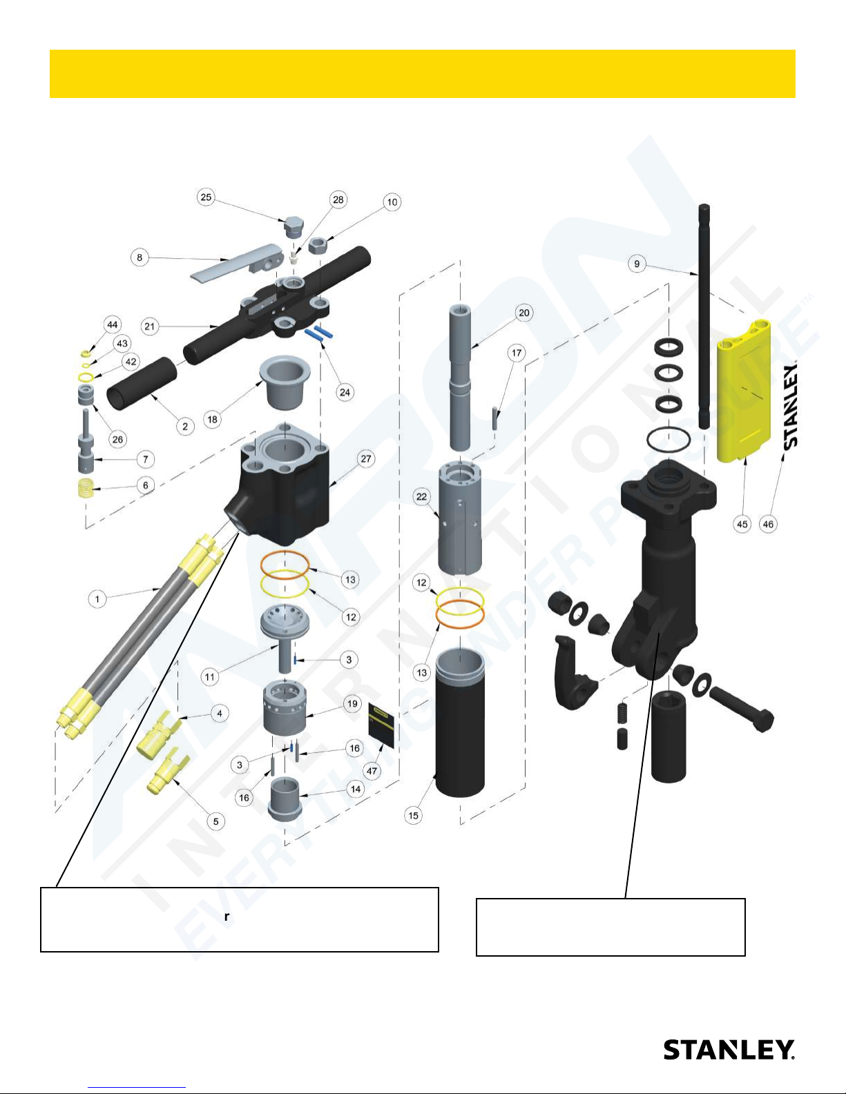
BR45 T-HANDLE PARTS ILLUSTRATION
Pictured is a BR45120
NOTE: 5-GPM Model (BR45550) has a Orice Plug P/N-12832
Installed in the lower return port of item 27 Accumulator
On-Off Valve Block (Orice Plug not pictured).
18 ► BR45 User Manual
See Pages 24 through 32 for Breaker Foot
Assemblies That Apply To Your Model.
Page 19
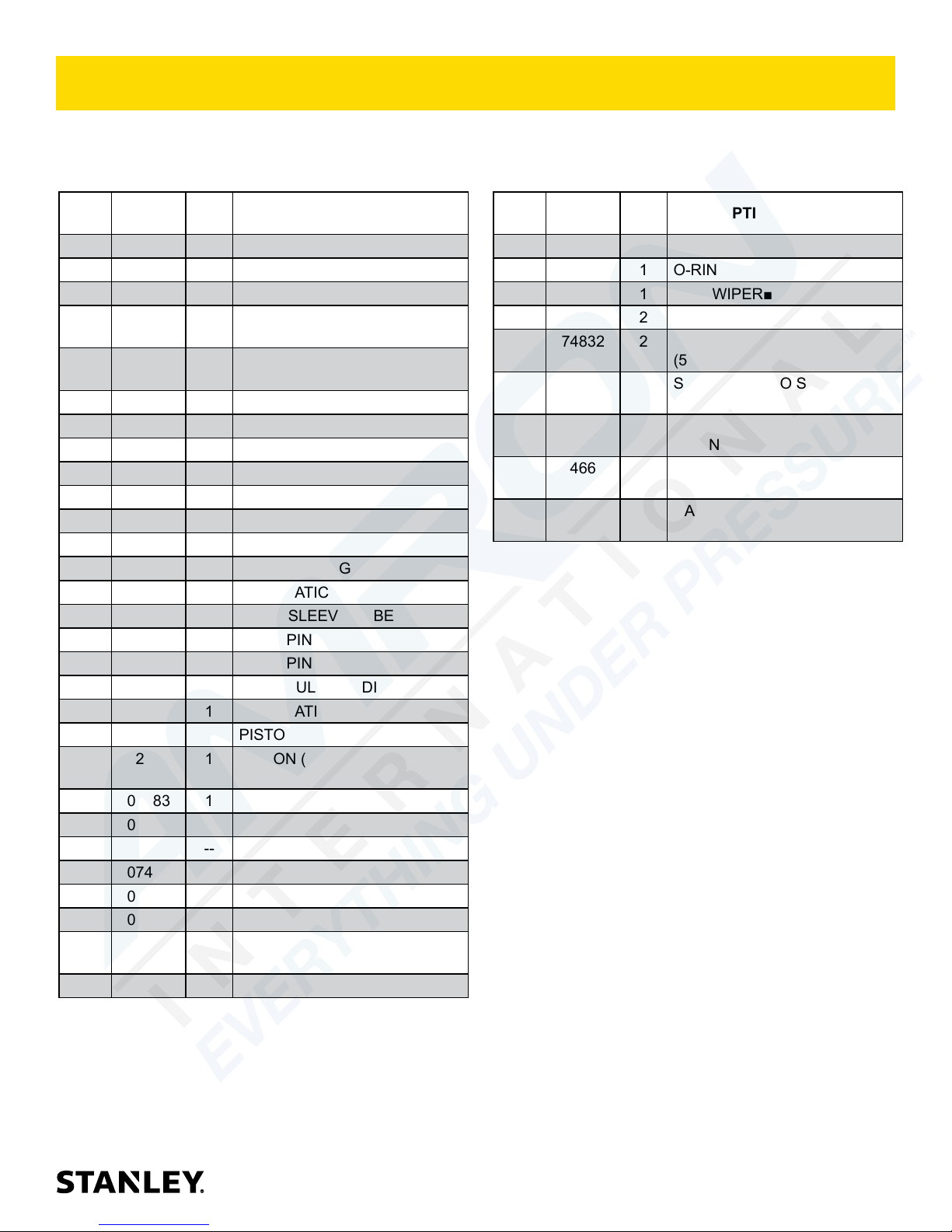
PARTS LIST
BR45 T-HANDLE PARTS LIST
ITEM
NO.
1 01652 2 HOSE WHIP 12"
2 02494 2 HANDLE GRIP
3 02900 2 ROLL PIN 1/8 O.D. X .500 LG.
4 03972 1 COUPLER,3/8FEM.3/8NPT
5 03973 1 COUPLER,3/8MALE 3/8NPT
6 04058 1 COMPRESSION COIL SPRING
7 04077 1 VALVE SPOOL
8 04371 1 TRIGGER
9 04373 4 SIDE ROD
10 04374 4 HEX NUT
11 04378 1 PORTING BLOCK
12 04379 2 O-RING■
13 04381 2 BACK-UP RING■
14 04382 1 AUTOMATIC VALVE
15 04383 1 FLOW SLEEVE TUBE
16 04571 2 PUSH PIN
17 04605 4 PUSH PIN
18 07479 1 ACCUMULATOR DIAPHRAGM
19 07480 1 AUTOMATIC VALVE BODY
20 07481 1 PISTON
21 07483 1 HANDLE
22 07485 1 FLOW SLEEVE
23 ----- -- NO ITEM
24 07492 2 ROLL PIN
25 07493 1 O-RING PLUG MALE
26 04057 1 BUSHING
27 11588 1 ACCUMULATOR ON-OFF
28 20499 1 CHARGE VALVE
PART
NO.
12833 1 PISTON (BR45550) (5-GPM
QTY DESCRIPTION
FL.FACE SET 03971
FL.FACE SET 03971
MODEL ONLY)
VALVE BLOCK
ITEM
NO.
42 00293 1 O-RING■
43 01362 1 O-RING■
44 04056 1 ROD WIPER■
45 72919 2 FILLER (SNAP ON)
46 74832 2 STANLEY LOGO STICKER
47 74664 1 NAME TAG BR45 (8-GPM)
SEAL KIT PART NUMBER 04595
■ DENOTES PART IN SEAL KIT
* DENOTES PART OF BREAKER FOOT ASSEMBLY
BUSHING ASSY 07699 (INCLUDES ITEMS 26,
42, 43, and 44)
PART
NO.
74770 2 STANLEY LOGO STICKER
74660 1 NAME TAG BR45 (5-GPM)
74669 1 NAME TAG BR45 (8-GPM)
QTY DESCRIPTION
(5.5” x 1.1” Black on Clear)
(6.5” x 1.3” Yellow on Clear)
T-HANDLE MODELS
T-HANDLE MODELS
T-HANDLE U/W MODEL
BR45 User Manual ◄ 19
Page 20
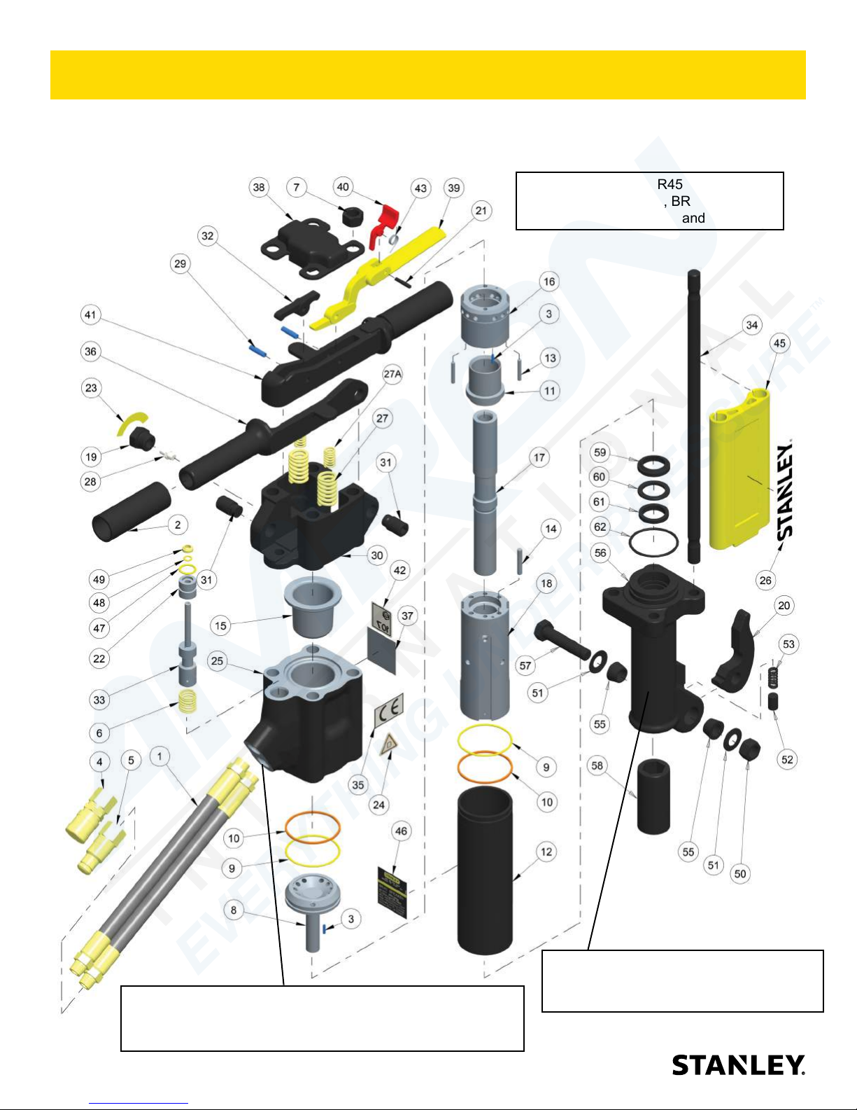
PARTS ILLUSTRATION
BR45 ANTI-VIBRATION HANDLE PARTS ILLUSTRATION
Pictured is a BR4516801
Models BR45125S, BR45135S,
BR4513516, BR45158, BR45158BN and
BR4556801 use parts 27 and 27A.
NOTE: 5-GPM Model (BR4556801) has a Orice Plug
P/N-12832 Installed in the lower return port of item 25
Accumulator On-Off Valve Block (Orice Plug not pictured).
20 ► BR45 User Manual
See Pages 24 through 32 for Breaker Foot
Assemblies That Apply To Your Model.
Page 21
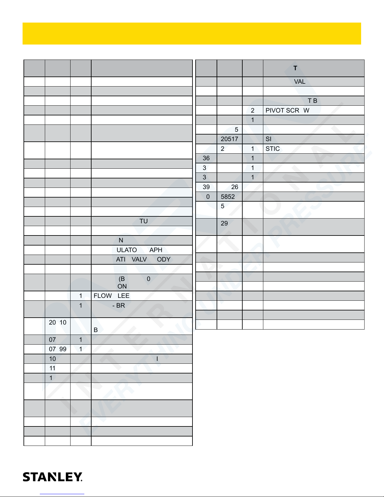
PARTS LIST
BR45 ANTI-VIBRATION HANDLE PARTS LIST
ITEM
NO.
27A 20541 2 SPRING BR45158/BR45158BN
PART
NO.
1 01652 2 HOSE WHIP 12"
56725 2 HOSE ASSY 18” BR45158
66727 2 HOSE ASSY BR45158BN
2 02494 2 HANDLE GRIP
3 02900 2 ROLL PIN
4 03972 1 COUPLER,3/8FEM. 3/8NPT
5 03973 1 COUPLER,3/8MALE 3/8NPT
6 04058 1 COMPRESSION COIL SPRING
7 04374 4 HEX NUT
8 04378 1 PORTING BLOCK
9 04379 2 O-RING*
10 04381 2 BACK-UP RING*
11 04382 1 AUTOMATIC VALVE
12 04383 1 FLOW SLEEVE TUBE
13 04571 2 PUSH PIN
14 04605 4 PUSH PIN
15 07479 1 ACCUMULATOR DIAPHRAGM
16 07480 1 AUTOMATIC VALVE BODY
17 07481 1 PISTON
12833 1 PISTON (BR4556801) (5-GPM
18 07485 1 FLOW SLEEVE
19 07493 1 PLUG - BR4514801, BR4516801,
20510 1 PLUG - BR45125S, BR45135S,
21 07624 1 ROLL PIN
22 07699 1 ◘ BUSHING ASSY.
23 10180 1 CAUTION N2 GAS STICKER
24 11207 1 CIRCUIT TYPE "D" STICKER
25 11588 1 ACCUMULATOR VALVE BLOCK
26 74832 2 STANLEY LOGO (5.5” x 1.1”
74770 STANLEY LOGO (6.5” x 1.3” Yel-
27 20498 2 SPRING
20540 2
QTY DESCRIPTION
FL.FACE SET 03971
FL.FACE SET 03971
MODEL ONLY)
BR4516807
BR4513516
Black on Clear)
low on Clear)
SPRING BR45158/BR45158BN
ITEM
NO.
PART
NO.
28 20499 1 CHARGE VALVE
29 20500 2 ROLL PIN
30 20505 1 HANDLE PIVOT BLOCK
31 20508 2 PIVOT SCREW
32 20511 1 LEVER
33 20515 1 VALVE SPOOL
34 20517 4 SIDE ROD
35 28322 1 STICKER "CE"
36 28369 1 HANDLE (GUARDED)
37 28409 1 COMPOSITE STICKER
38 28494 1 TOP PLATE
39 58526 1 CAST TRIGGER
40 58527 1 TRIGGER LOCK
41 58529 1 TRIGGER HANDLE (WITH TRIG-
29045 1 TRIGGER HANDLE (NON-TRIG-
42 58601 1 GUARANTEED SOUND POWER
43 66828 1 TORSION SPRING
45 72919 2 FILLER (SNAP-ON)
46 74663 1 NAME TAG-BR45 8-GPM
74659 1 NAME TAG-BR45 5-GPM
47 00293 1 O-RING*
48 01362 1 O-RING*
49 04056 1 ROD WIPER*
52 04393 1 DETENT
SEAL KIT PART NUMBER 04595
■ DENOTES PART IN SEAL KIT
* DENOTES PART OF BREAKER FOOT ASSEMBLY
◘ BUSHING ASSY 07699 (INCLUDES ITEMS 22,
47, 48, and 49)
QTY DESCRIPTION
GER LOCK
GER LOCK
LEVEL - 107dB
BR45 User Manual ◄ 21
Page 22
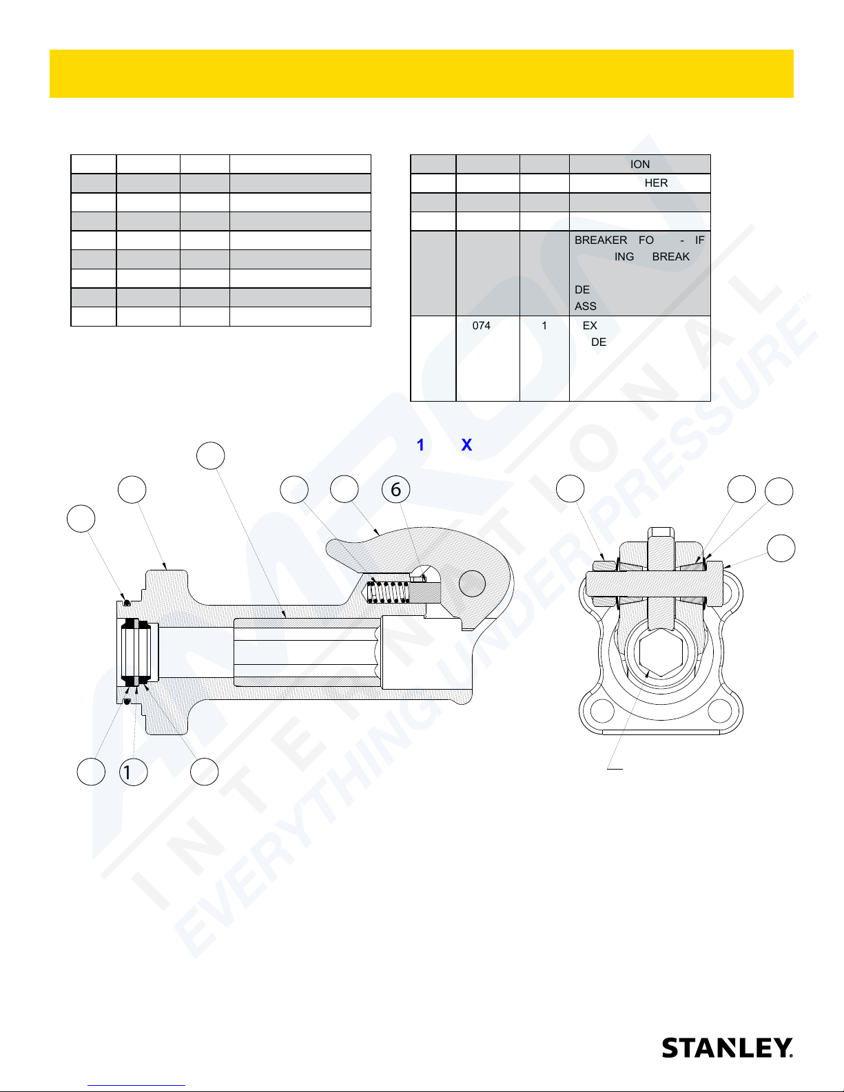
BREAKER FOOT ASSEMBLY 07489
BREAKER FOOT ASSEMBLY (STANDARD) P/N-07489 (MODELS BR45150, BR45550, BR45158, BR45158BN)
07489 Assembly Includes Items 1 through 13 Below.
ITEM PART # QTY DESCRIPTION
1 02022 1 O-RING
2 04374 1 HEX NUT
3 04386 1 CUP SEAL
4 04387 1 ROD WIPER
5 04392 1 SPRING
6 04393 1 DETENT
7 04394 1 LATCH
8 04715 2 TAPER SLEEVE
NOTE: IF YOU ARE REPLACING THE INSERT,
BREAKER FOOT OR HEX BUSHING YOU MUST
PURCHASE A COMPLETE BREAKER FOOT
ASSEMBLY P/N-72931
13
12
5
7
1
ITEM PART # QTY DESCRIPTION
9 04716 2 SPRING WASHER
10 04717 1 LATCH BOLT
11 04780 1 BACK UP WASHER
12 07489 1 BREAKER FOOT - IF
ORDERING BREAKER
FOOT YOU MUST OR-
DER COMPLETE FOOT
ASSY 07489.
13 07489 1 HEX BUSHING 1" IF
ORDERING HEX BUSH-
ING YOU MUST ORDER
COMPLETE FOOT ASSY
07489.
1” HEX
6
2
8
9
10
3
11
22 ► BR45 User Manual
4
ALIGN HEX AS SHOWN
Page 23
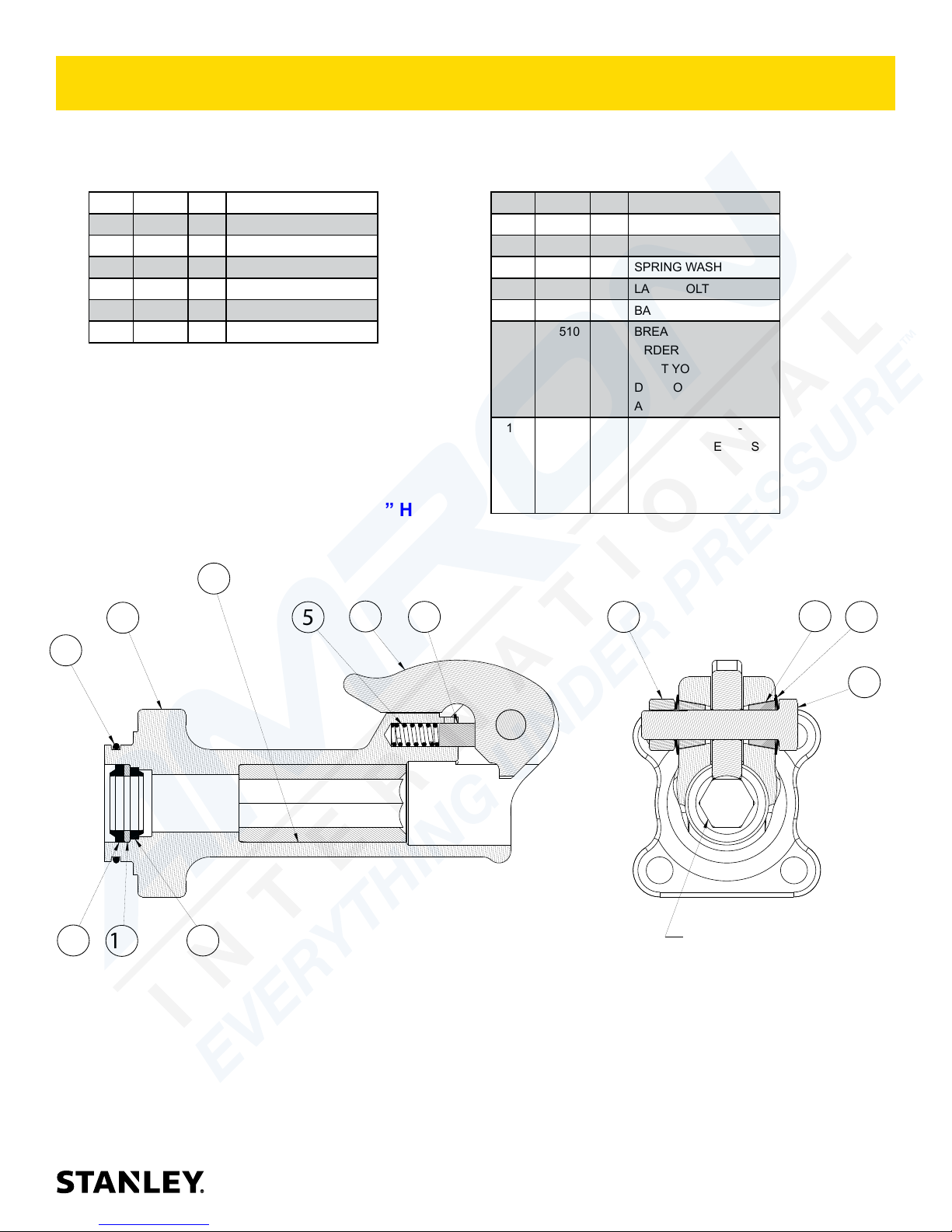
BREAKER FOOT ASSEMBLY 07510
BREAKER FOOT ASSEMBLY (STANDARD) P/N-07510 (MODELS BR4516801, BR4516807, BR4516807A and
BR4556801). 07510 Assembly Includes Items 1 through 13 Below.
ITEM PART # QTY DESCRIPTION
1 02022 1 O-RING
2 04374 1 HEX NUT
3 04386 1 CUP SEAL
4 04387 1 ROD WIPER
5 04392 1 SPRING
6 04393 1 DETENT
NOTE: IF YOU ARE REPLACING THE INSERT,
BREAKER FOOT OR HEX BUSHING YOU MUST
PURCHASE A COMPLETE BREAKER FOOT
ASSEMBLY P/N-72931
1” HEX
13
12
5
7
6
ITEM PART # QTY DESCRIPTION
7 04394 1 LATCH
8 04715 2 TAPER SLEEVE
9 04716 2 SPRING WASHER
10 04717 1 LATCH BOLT
11 04780 1 BACK UP WASHER
12 07510 1 BREAKER FOOT - IF
ORDERING BREAKER
FOOT YOU MUST OR-
DER COMPLETE FOOT
ASSY 07510.
13 07510 1 HEX BUSHING 1" - IF
ORDERING HEX BUSH-
ING YOU MUST ORDER
COMPLETE FOOT
ASSY 07510
2
8
9
1
10
11
43
ALIGN HEX AS SHOWN
BR45 User Manual ◄ 23
Page 24
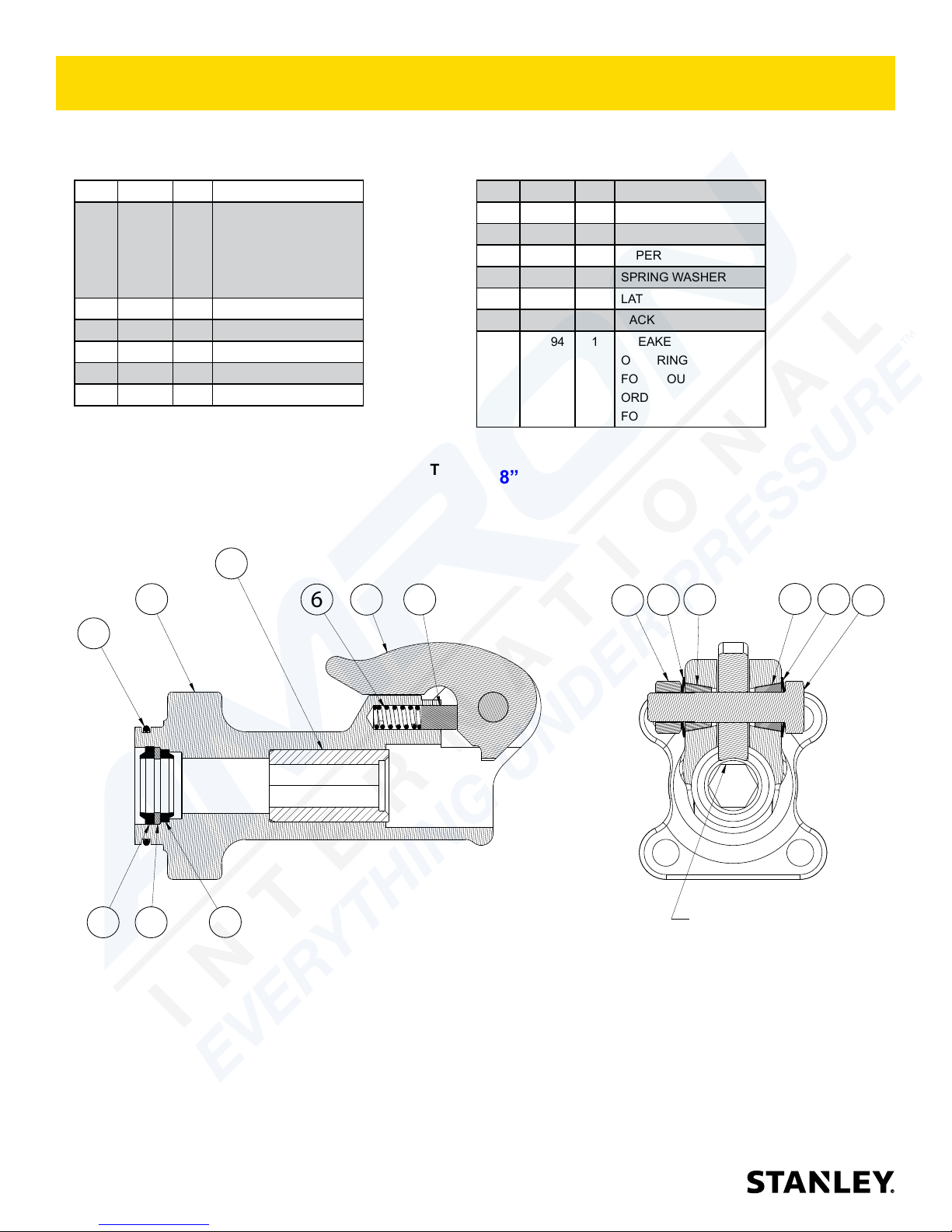
BREAKER FOOT ASSEMBLY 07694
BREAKER FOOT ASSEMBLY (STANDARD) P/N-07694 (MODEL BR4514801)
07694 Assembly Includes Items 1 through 13 Below.
ITEM PART # QTY DESCRIPTION
1 07694 1 HEX BUSHING 7/8”
- IF ORDERING HEX
BUSHING YOU MUST
ORDER COMPLETE
FOOT ASSY 07694
2 02022 1 O-RING
3 04374 1 HEX NUT
4 04386 1 CUP SEAL
5 04387 1 ROD WIPER
6 04392 1 SPRING
NOTE: IF YOU ARE REPLACING THE INSERT,
BREAKER FOOT OR HEX BUSHING YOU MUST
PURCHASE A COMPLETE BREAKER FOOT
ASSEMBLY P/N-72931
1
13
6
8
7
2
ITEM PART # QTY DESCRIPTION
7 04393 1 DETENT
8 04394 1 LATCH
9 04715 2 TAPER SLEEVE
10 04716 2 SPRING WASHER
11 04717 1 LATCH BOLT
12 04780 1 BACK UP WASHER
13 07694 1 BREAKER FOOT - IF
ORDERING BREAKER
FOOT YOU MUST
ORDER COMPLETE
FOOT ASSY 07694.
7/8” HEX
9
10
3
9
10
11
4
12
24 ► BR45 User Manual
5
ALIGN HEX AS SHOWN
Page 25
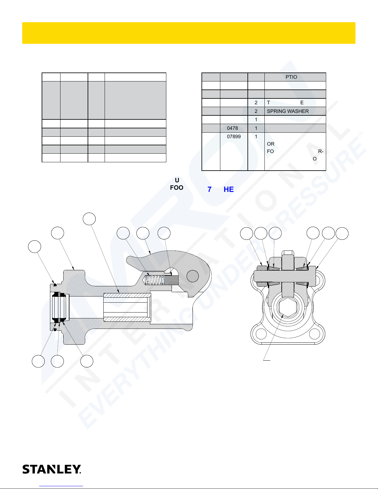
BREAKER FOOT ASSEMBLY 07899
BREAKER FOOT ASSEMBLY (STANDARD) P/N-07899 (MODEL BR45110)
07899 Assembly Includes Items 1 through 13 Below.
ITEM PART # QTY DESCRIPTION
1 07899 1 HEX BUSHING - IF OR-
DERING HEX BUSH-
ING YOU MUST ORDER
COMPLETE FOOT ASSY
07899
2 02022 1 O-RING
3 04374 1 HEX NUT
4 04386 1 CUP SEAL
5 04387 1 ROD WIPER
6 04392 1 SPRING
NOTE: IF YOU ARE REPLACING THE INSERT,
BREAKER FOOT OR HEX BUSHING YOU MUST
PURCHASE A COMPLETE BREAKER FOOT
ASSEMBLY P/N-72931
1
13
6
8
2
ITEM PART # QTY DESCRIPTION
7 04393 1 DETENT
8 04394 1 LATCH
9 04715 2 TAPER SLEEVE
10 04716 2 SPRING WASHER
11 04717 1 LATCH BOLT
12 04780 1 BACK UP WASHER
13 07899 1 BREAKER FOOT - IF
ORDERING BREAKER
FOOT YOU MUST OR-
DER COMPLETE FOOT
ASSY 07899
7/8” HEX
7
3
10
9
9
10
11
4
12
5
ALIGN HEX AS SHOWN
BR45 User Manual ◄ 25
Page 26
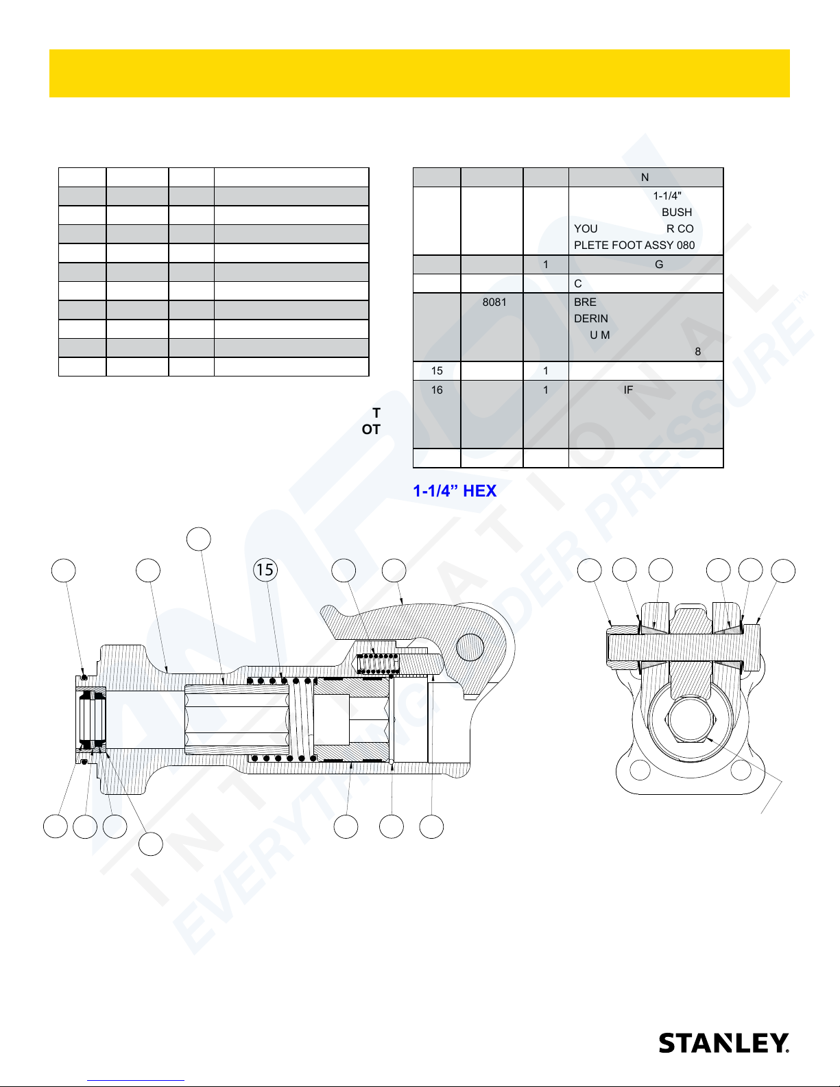
BREAKER FOOT ASSEMBLY 08081
BREAKER FOOT ASSEMBLY (EASY-RIDE) P/N-08081 (MODELS BR45130E, BR45130EL, BR45135S and
BR4513516). 08081 Assembly Includes Items 1 through 17 Below.
ITEM PART # QTY DESCRIPTION
1 01269 2 TAPER SLEEVE
2 01744 1 SPRING
3 01837 1 LATCH
4 02022 1 O-RING
5 04386 1 CUP SEAL
6 04387 1 ROD WIPER
7 04780 1 BACK UP WASHER
8 04983 1 FOOT LATCH BOLT
9 04984 1 NYLOCK NUT
10 04985 2 SPRING WASHER
NOTE: IF YOU ARE REPLACING THE INSERT,
BREAKER FOOT OR HEX BUSHING YOU MUST
PURCHASE A COMPLETE BREAKER FOOT
ASSEMBLY P/N-72931
11
4
14
15
2
ITEM PART # QTY DESCRIPTION
11 08081 1 HEX BUSHING 1-1/4" - IF
12 07522 1 RETAINING RING
13 08116 1 COLLAR SUPPORT ASSY.
14 08081 1 BREAKER FOOT - IF OR-
15 08158 1 SPRING
16 08081 1 INSERT - IF ORDERING
17 08411 1 DETENT
1-1/4” HEX
3
ORDERING HEX BUSHING
YOU MUST ORDER COM-
PLETE FOOT ASSY 08081
DERING BREAKER FOOT
YOU MUST ORDER COM-
PLETE FOOT ASSY 08081
THE INSERT YOU MUST
ORDER COMPLETE FOOT
ASSY 08081
10
9
1
10
1
8
5
6
7
16
26 ► BR45 User Manual
13
12
ALIGN HEX AS SHOWN
17
Page 27
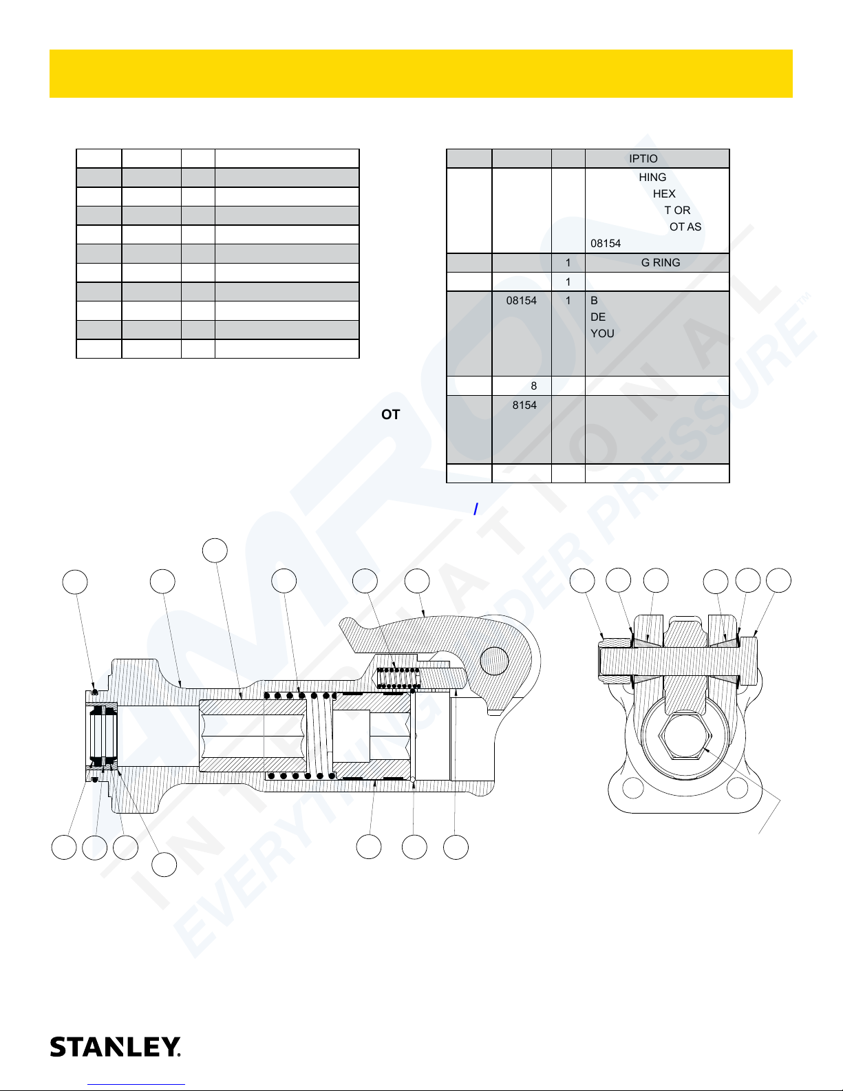
BREAKER FOOT ASSEMBLY 08154
BREAKER FOOT ASSEMBLY (EASY-RIDE) P/N-08154 (MODELS BR45120E and BR45125S)
08154 Assembly Includes Items 1 through 17 Below.
ITEM PART # QTY DESCRIPTION
1 01269 2 TAPER SLEEVE
2 01744 1 SPRING
3 01837 1 LATCH
4 02022 1 O-RING
5 04386 1 CUP SEAL
6 04387 1 ROD WIPER
7 04780 1 BACK UP WASHER
8 04983 1 FOOT LATCH BOLT
9 04984 1 NYLOCK NUT
10 04985 2 SPRING WASHER
NOTE: IF YOU ARE REPLACING THE INSERT,
BREAKER FOOT OR HEX BUSHING YOU MUST
PURCHASE A COMPLETE BREAKER FOOT
ASSEMBLY P/N-72931
11
ITEM PART # QTY DESCRIPTION
11 08154 1 HEX BUSHING 1-1/8" - IF
ORDERING HEX BUSH-
ING YOU MUST ORDER
COMPLETE FOOT ASSY
08154
12 07522 1 RETAINING RING
13 08115 1 COLLAR SUPPORT ASSY.
14 08154 1 BREAKER FOOT - IF OR-
DERING BREAKER FOOT
YOU MUST ORDER
COMPLETE FOOT ASSY
08154
15 08158 1 SPRING
16 08154 1 INSERT - IF ORDERING
THE INSERT YOU MUST
ORDER COMPLETE
FOOT ASSY 08154
17 08411 1 DETENT
1-1/8” HEX
10
4
5
7
14
6
15
2
13
12
3
17
9
1
ALIGN HEX AS SHOWN
10
1
8
16
BR45 User Manual ◄ 27
Page 28
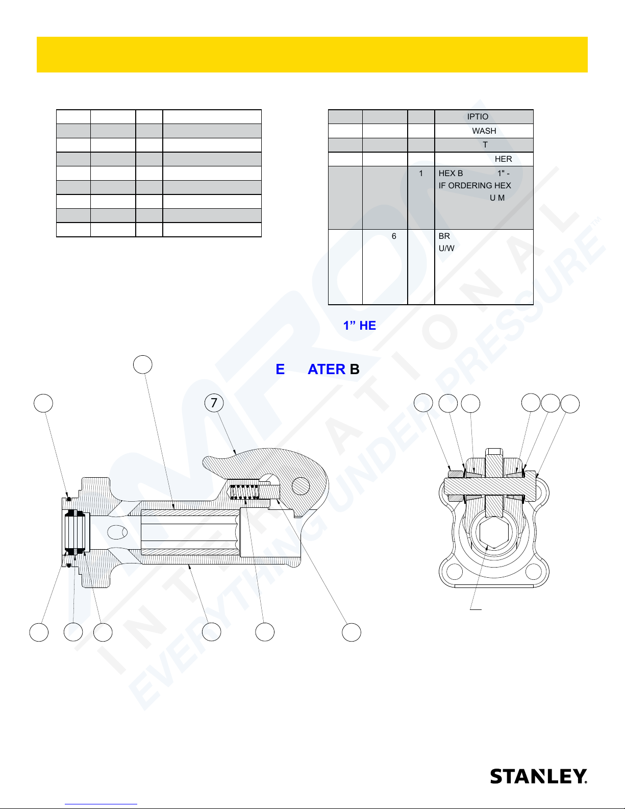
BREAKER FOOT ASSEMBLY 08856
BREAKER FOOT ASSEMBLY (UNDERWATER) P/N-08856 (MODELS BR45350)
08856 Assembly Includes Items 1 through 13 Below.
ITEM PART # QTY DESCRIPTION
1 02022 1 O-RING
2 04374 1 HEX NUT
3 04386 1 CUP SEAL
4 04387 1 ROD WIPER
5 04392 1 SPRING
6 04393 1 DETENT
7 04394 1 LATCH
8 04715 2 TAPER SLEEVE
NOTE: IF YOU ARE REPLACING THE INSERT,
BREAKER FOOT OR HEX BUSHING YOU MUST
PURCHASE A COMPLETE BREAKER FOOT
ASSEMBLY P/N-72931
12
1
7
UNDERWATER BREAKER
ITEM PART # QTY DESCRIPTION
9 04716 2 SPRING WASHER
10 04717 1 LATCH BOLT
11 04780 1 BACK UP WASHER
12 08856 1 HEX BUSHING 1" -
13 08856 1 BREAKER FOOT
1” HEX
FOOT ASSY
IF ORDERING HEX
BUSHING YOU MUST
ORDER COMPLETE
FOOT ASSY 08856
U/W - IF ORDERING
BREAKER FOOT
YOU MUST ORDER
COMPLETE FOOT
ASSY 08856
2
9
8
8
9
10
11
3
28 ► BR45 User Manual
4
13
ALIGN HEX AS SHOWN
5
6
Page 29
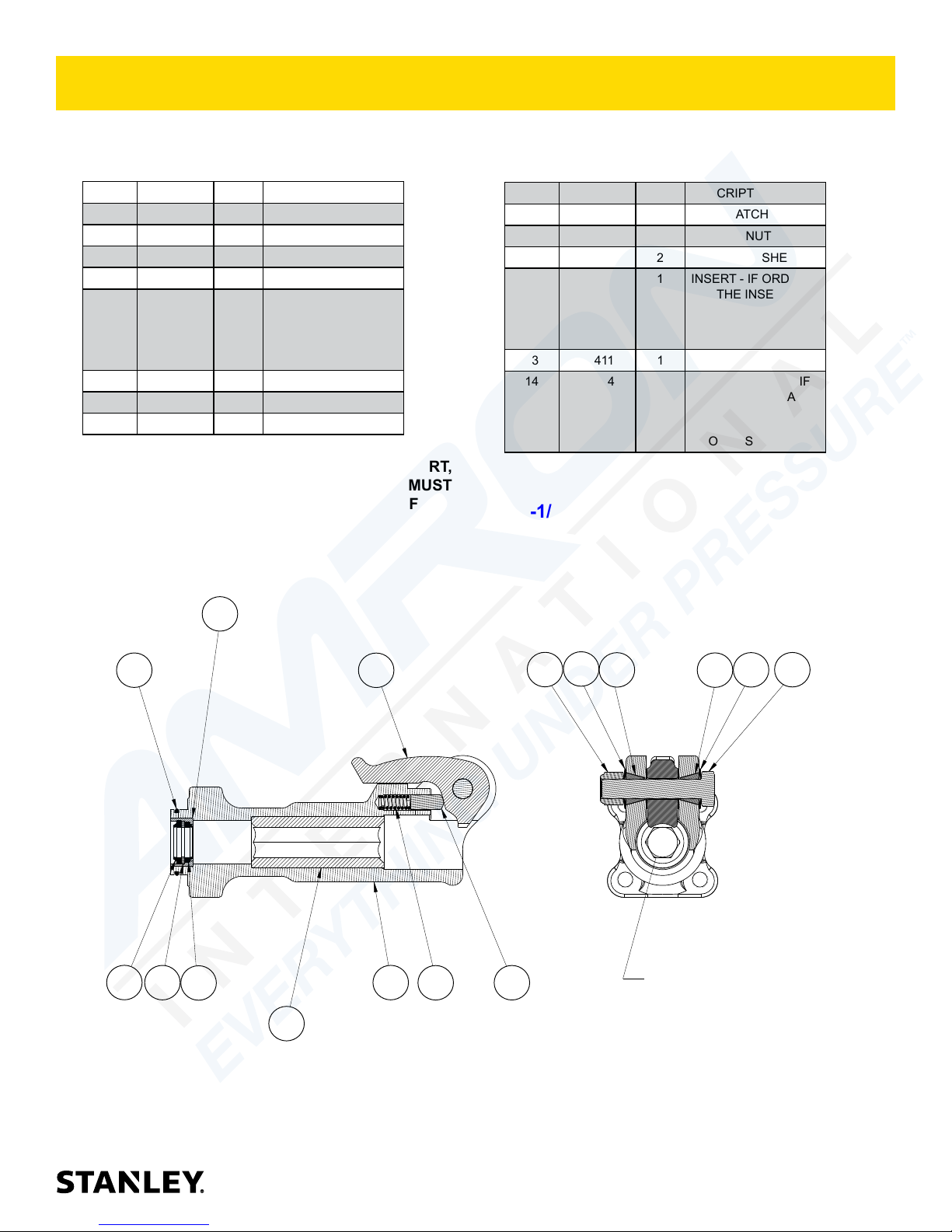
BREAKER FOOT ASSEMBLY 62334
BREAKER FOOT ASSEMBLY (STANDARD) P/N-62334 (MODELS BR45120 and BR45120D)
62334 Assembly Includes Items 1 through 14 Below.
ITEM PART # QTY DESCRIPTION
1 01269 2 TAPER SLEEVE
2 01744 1 SPRING
3 01837 1 LATCH
4 02022 1 O-RING
5 62334 1 HEX BUSHING 1-1/8"
- IF ORDERING HEX
BUSHING YOU MUST
ORDER COMPLETE
FOOT ASSY 62334
6 04386 1 CUP SEAL
7 04387 1 ROD WIPER
8 04780 1 BACK UP WASHER
NOTE: IF YOU ARE REPLACING THE INSERT,
BREAKER FOOT OR HEX BUSHING YOU MUST
PURCHASE A COMPLETE BREAKER FOOT
ASSEMBLY P/N-72931
12
ITEM PART # QTY DESCRIPTION
9 04983 1 FOOT LATCH BOLT
10 04984 1 NYLOCK NUT
11 04985 2 SPRING WASHER
12 62334 1 INSERT - IF ORDER-
ING THE INSERT
YOU MUST ORDER
COMPLETE FOOT
ASSY 62334
13 08411 1 DETENT
14 62334 1 BREAKER FOOT - IF
ORDERING BREAKER FOOT YOU MUST
ORDER COMPLETE
FOOT ASSY 62334
1-1/8” HEX
6
4
8
7
5
3
14
2
13
10
11
1
1
ALIGN HEX AS SHOWN
11
9
BR45 User Manual ◄ 29
Page 30
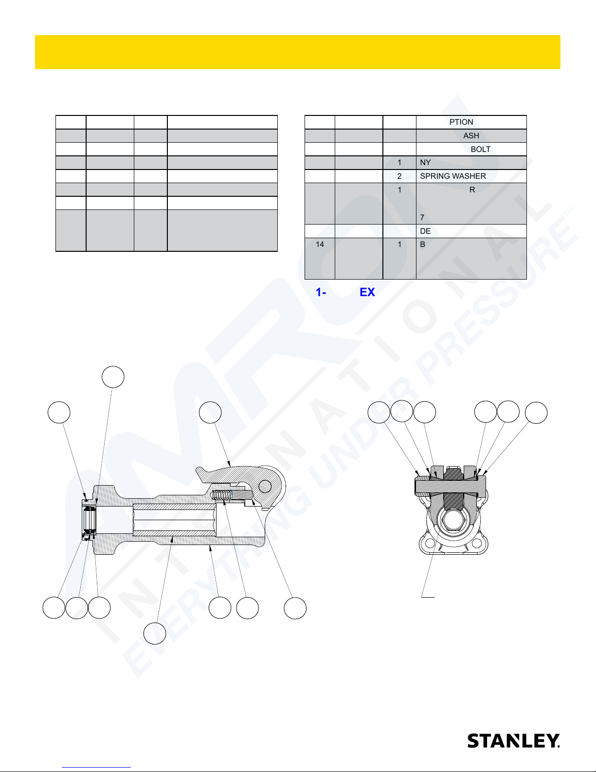
BREAKER FOOT ASSEMBLY 72931
BREAKER FOOT ASSEMBLY (STANDARD) P/N-72931 (MODEL BR45130)
72931 Assembly Includes Items 1 through 14 Below.
ITEM PART # QTY DESCRIPTION
1 01269 2 TAPER SLEEVE
2 01744 1 SPRING
3 01837 1 LATCH
4 02022 1 O-RING
5 04386 1 CUP SEAL
6 04387 1 ROD WIPER
7 72931 1 HEX BUSHING 1-1/4" - IF
ORDERING HEX BUSHING
YOU MUST ORDER COMPLETE FOOT ASSY 72931
NOTE: IF YOU ARE REPLACING THE INSERT, BREAKER
FOOT OR HEX BUSHING YOU MUST PURCHASE A COMPLETE BREAKER FOOT ASSEMBLY P/N-72931
12
ITEM PART # QTY DESCRIPTION
8 04780 1 BACK UP WASHER
9 04983 1 FOOT LATCH BOLT
10 04984 1 NYLOCK NUT
11 04985 2 SPRING WASHER
12 72931 1 INSERT - IF ORDERING THE
INSERT YOU MUST ORDER
COMPLETE FOOT ASSY
72931
13 08411 1 DETENT
14 72931 1 BREAKER FOOT - IF OR-
DERING BREAKER FOOT
YOU MUST ORDER COMPLETE FOOT ASSY 72931
1-1/4” HEX
5
4
8
6
7
3
14
2
13
10
11
11
1
1
ALIGN HEX AS SHOWN
9
30 ► BR45 User Manual
Page 31
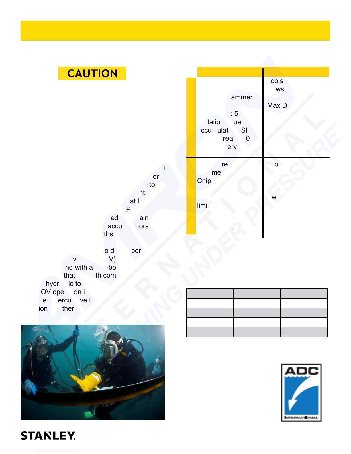
UNDERWATER TOOLS DEPTH GUIDELINE
UNDERWATER MODELS
ONLY BR45350
DO NOT USE HYDRAULIC TOOLS
THAT ARE NOT DESIGNATED AS AN
“UNDERWATER” MODEL, OR THIS WILL
RESULT IN DAMAGE TO THE TOOL.
For underwater hydraulic tools the applications are
broken down into four quadrants depending on
type of tool and method of operation.
Operation Overview
Percussive Rotational
Tools: Breakers,
Hammer Drills and
Chipping Hammers
Max Depth: 500' -
DiverROV
limitations due to
accumulator PSI
max (increase 40
PSI for every 100')
Tools: Grinders,
Saws, Chain Saws
Max Depth: 1000' Reference hose
sizing guide below
The types of tools are percussive and rotational,
each with different characteristics allowing for
different depth operation. With percussive tools,
the nitrogen accumulator PSI must counter the
increase in ambient pressure found at lower
depths. Since there is a maximum PSI for
percussive tools they are limited to certain depths.
Rotational tools do not have accumulators and
thus capable of deeper depths.
The methods are broken into diver operated or
remote operated vehicle (ROV). ROV's can reach
lower depths and with an on-board hydraulic
power source that is depth compensated, can
operate hydraulic tools at depths of thousands of
feet. ROV operation is still limited to the tool, for
example a percussive tool has the same depth
limitation whether ROV or diver operated.
Tools: Breakers,
Hammer Drills and
Chipping Hammers
Max Depth: 500' limitations due to
accumulator PSI
max (increase 40
PSI for every 100')
Tools: Grinders,
Saws, Chain Saws
Max Depth: 1000' Reference hose
sizing guide below
Recommended Hose Diameters
Depth (ft) 8 GPM 12 GPM
100 5/8” 5/8”
300 3/4” 1”
600 1” 1”
1000 1” 1-1/4”
BR45 User Manual ◄ 31
Page 32

STANLEY Infrastructure
6430 SE Lake Road
Portland, Oregon 97222 USA
(503) 659-5660 / Fax (503) 652-1780
www.stanleyinfrastructure.com
 Loading...