

Page 1
To assure product SAFETY and RELIABiLITY, repairs, maintenance and adjust
ment should be performed by BLACK & DECKER Service Centers or other qualified
service organizations, always using Black & Decker replacement parts.
Black 8i Decker (U.S.) Inc. warrants this product for one year from date of
purchase. We will repair without charge, any defects due to faulty material or workman
ship. Please return the complete unit, transportation prepaid, to any Black & Decker
Service Center or Authorized Service Station listed under “Tools Electric” in the yellow
pages. This warranty does not apply to accessories or damage caused where repairs
have been made or attempted by others.
Like most Black & Decker products your tool is listed by Underwriters Laboratories
to ensure that it meets stringent safety requirements.
This symbol on the nameplate means the product
is listed by Underwriters Laboratories. Inc.
See Tools-Electric’
-Yellow Pages-
for Service & Sales
#
5065
Form No. 741782
Black & Decker (U.S.) Inc., U.S. Power Tools Group, P.O. 798, Hunt Valley, MD 21030-0798 U.S.A,
C-1989 Black & Decker (April 89)
Printed in Italy
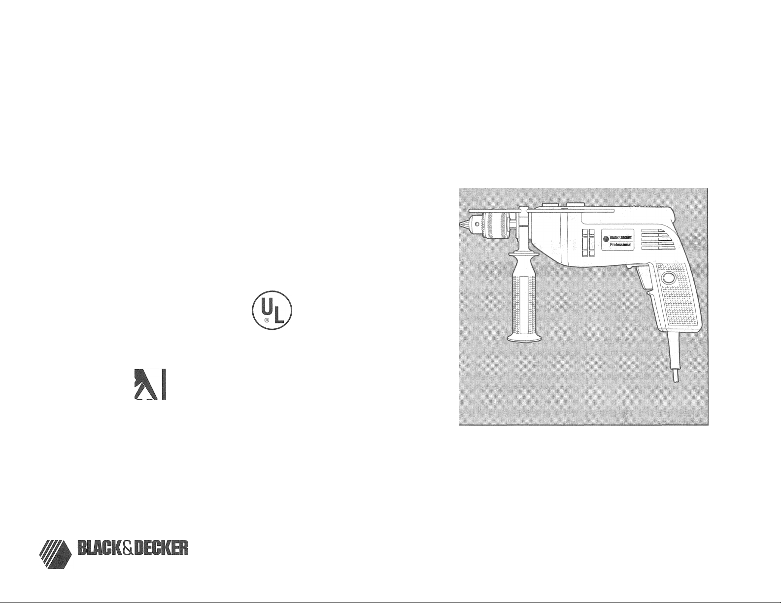
1/2" Dual Range
Hammer Drill
S065
Page 2

Additional Safety
Information For Drills
1. The switch lock feature must be
used 'With caution due to the high
torque output of the tool (See Figure
1). , ,
2. Do not attempt to change from
hammer to drill mode while tool is
running.
The Variable Speed Trigger Switch
permits speed control. The farther the
trigger is depressed, the higher the
speed of the unit.
For maximum tool life, use lower
speed only for starting the hole. Continu
ous use at lower speed is not recom
mended.
The Reversing Lever is used for
removing jammed drill bits, or backing
out screws. It is located above the trigger
switch, as shown in Figure 2. To operate
the tool, in reverse, push the reversing
lever to the right, shown in Figure 2.
When reversing operations are con
cluded, return the lever to the forward
Dosition, as shown in the figure.
Stop
Capacity 'I/4" to 1/2" Governs
drilling depth.
Wire Wheel Brushes
Use in cleaning and «'amoving rust,
scale, old paint. 4" Fine Brush, crimped:
Viaximum sate PPM—4,500 4" Coarse
Brush, crimped; Maximum safe RPM—
^O500.
Buffing Wheels
Use with 1/4" to 1/2" Drills and
Wheel Arbors. 3" x 3/8" x 1/2" Cotton
Buff.
è
Rubber Backing Pad
Fit 1/4" to 1/2" Drills. 4-5/8" Rubber
Backing Pad with plain shanK. Used «or
sanding operations.
Switches
To start unit, depress trigger switch;
to stop unit, release trigger. To lock
trigger in “ON" position for continuous
operation, depress trigger and push in
locking button Figure 1, then gently
release trigger. To release locking
mechanism, depress trigger fully, then
release it. Before using the tool {each
time) be sure that the lock button release
mechanism is v\/orking freely.
Be sure to release the switch
locking button before disconnecting the
?c cause the tool to start immediately
the rex: hr*e *: T c'ugced ;c. Damage or
injury could result
WARNING: The switch lock feature
must be used with caution due to the
high torque output of this unit.
Brushes
Your tool is equipped with Black &
Decker brush checkpoint system. When
the brushes become worn out the tool
will automatically stop and prevent
damage to the motor. Return the tool to a
Black & Decker Service Center for brush
replacement. ^ a ^ {
#1
Wheel Arbors
Fit 1/4" to 1/2" Drills. Carry wire
wheel brushes and buffing wheels.
L
»
Sanding Discs
Use with Rubber Sacking Pad.
J
Page 3

Drilling in Masonry
Refer to the same list of instructions
under ‘DRILLING’', but use percussion
Masonry drill bits only. Drill in masonry
only. Keep even force on the drill but not
so much that you crack the brittle
materials. A smooth, even flow of dust
indicates the proper drilling rate.
Drill Accessories
The accessories listed in this manua,
are available at extra cost from your local
dealer or Black & Decker Service Center.
A complete listing o1 service centers is
included on tne owner’s registration card
packed witri your tool.
If you need assistance in locating
any accessory, please coniac:: Black &
Decker, (U.S.' me.. User Services
Department, 626 Hanover Pike, P.O. Box
618, Hampstead, MD 21074-0618.
Every Black S Decker loo' is oi the
highest quality. !i you wish to contact us
regarding this product, please call toll free
between 8:00 a.m. and 5:00 p.m. EST
Monday through Friday. 1 -800-762-6672
Recommended accessories io" you:
Drill are shown in this manual (CAUTION:
The use of any other accessory might be
hazardous.) For safety in use, the
following accessories should be useo onlv
in si.zes UD to the maximums snowri in
table below.
Maximum Recommended Capacities
DRILL CAPACITY
R.P.M.
BITS, METAL DRILLING
WOOD, FLAT BORING
BITS, MASONRY DRILLING 3/4"
HOLE SAWS
WIRE WHEEL BRUSHESWIRE CUP BRUSHES —
BUFFING WHEELS
RUBBER BACKING-
PADS
0-900/0-2200
1/2"
1"
1-1/8"
— 4" Dia. Max.
3" Dia. Max.
— 3" Dia. Max.
■ 4-5/8" Dia. Max.
ACCESSORY MUST BE RATED FOR
USE AT SPEED EQUAL TO OR
HIGHER THAN N.AMEPLATE R.P.M.
OF TOOL WITH WHICH IT IS BEING
USED.
Carbon Removing
Brushes
Made of tempered-steel wire; used
with drills to remove rust and scale from
metals. Leaves a burnished surface.
A. Heavy-duty solid wire-filled brush.
B. Side-flare brusii for close corner
work
C. Hollow-core flare-bottoiTi brush.
Small cleaning brush. (No: shown.'
3" Wire Cup Brush
Use in cleaning and removing rust,
scaie, old pain.. (Straight chuck snank,.
Maximum safe RPM—5,000.
mil
Your Hammer Drill is equipped with
dual range speed control for greater
versatility. To change from one range to
the other, turn the too! off and then rotate
the range control dial. shov\/n in Figure 3,
to the desired position. Turn Hie dial so
that the symbol 1 is toward the chuck for
low speed (0-90C RPM). If you want high
speed (0-2200 RPM) lurn the dial so thal
the symbol li is toward the chuck
NO"!"E; It may sometimes be necessary
to manually turn the spindle slightly
when shitting from one ranae to anot'nei.
DO NOT SHIFT WHEN THE TOOL IS
RUNNING OR COASTING.
The tool mus- be fully engaged into
range I or range II. Make sure that the
selector is noi somewhere between the
two; damage to the unit may result.
IHilil
Hammer/Drill Selector
To switch the tool from the drilling mode j
to the hammering moae io- vice-versa) ;
rotate the dial, snown m Figure 4, so that |
tne desirec position is accomolisheo. For |
straigh: driliing. align the drÜ! bit symbol
i toward the chuck. For hammering, align
\ the hammer symbol with the chuck, as
stiown in the figure.
NOTE: The selector must be in either
drill or hammer mode at all times. There
are no operable positions between the
two.
Ciici lii ief
UNPLUG DRILL. Open chuck jaws
and inserì shank of bi; aboui inio
chuck. Tighten chuck collar by hand.
Place chuck key in each of the three
•loles, and iigkaen ir clockwise direction.
It’s important to tighten chuck with all
three holes to prevent slippage of drill bit
in chuck. To release bit, turn chuck key
coLinierciocKwise in
loosen chuck by hand.
jusi one hoie, ther
Chuck Key Holder
1. Push double-hole end of holder
through slot in other end of Holder.
(Figure 5).
2. Slip loop over electric plug and draw
loop tight around cord (Figure 6).
3. Push ends of Chuck Key Handle
through two holes in end of Holder
(Figure 7).
Page 4

Multi-Position Side Handle
This handle clamps to the front of the
tool and can be rotated to permit right-
hand or left-hand use. (Figure 8).
CAUTION: Always use Side Handle
and hold drill with both hands.
RANGE CONTROL DIAL
MULTI-POSITION —
SIDE HANDLE
HAMMER/DRILL SELECTOR
LOCKING
BUTTON
5. Hold tool firmly to control the
twisting action of the drill.
6. IF DRILL STALLS, it is usually
because it is being overloaded or
improperly used. RELEASE
TRIGGER IMMEDIATELY, remove
drill bit from work, and determine
cause of stalling. DO NOT CLICK
TRIGGER OFF AND ON IN AN
ATTEMPT TO START A STALLED
DRILL — THIS CAN DAMAGE
THE DRILL.
7. To minimize stalling or breaking
through the material, reduce
pressure on drill and ease the bit
through the last fractional part of the
hole.
8. Keep the motor running when
pulling the bit back out of a drilled
hole. This will help prevent jamming.
9. With Variable Speed Drills there is
no need to center punch the point to
be drilled. Use a slow speed to start
the hole and accelerate by
squeezing the trigger harder when
the hole is deep enough to drill
without the bit skipping out.
DRILLING
1. Always unplug the Drill when
attaching or changing bits or
accessories.
2. Use sharp drill bits only. For
WOOD, use twist drill bits, spade
bits, power auger bits, or hole saws.
For METAL, use high speed steel
twist drill bits or hole saws.
3. Be sure the material to be drilled is
anchored or clamped firmly. If
drilling thin material, use a wood
“back-up” block to prevent damage
to the material.
4. Always apply pressure in a straight
line with the bit. Use enough
pressure to keep drill biting, but do
not push hard enough to stall the
motor or deflect the bit.
Use a cutting lubricant when drilling
metals. The exceptions are cast iron and
brass which should be drilled dry. The
cutting lubricants that work best are
sulphurized cutting oil or lard oil; bacongrease will also serve the purpose.
NOTE: Large (5/16" to 3/8") holes in
steel can be made easier if a pilot hole
(5/32" to 3/16") is drilled first.
Holes in wood can be made with the
same twist drills used for metal. These
bits may overheat unless pulled out
frequently to clear chips from the flutes.
For larger holes, use Power Drill Wood
Bits. Work that is apt to splinter should
be backed up with a block of wood.
Page 5

Drilling in Masonry
Refer to the same list of instructions
under “DRILLING", but use percussion
Masonry drill bits only. Drill in masonry-
only. Keep even force on the drill but not
so much that you crack the brittle
materials. A smooth, even flow of dust
indicates the proper drilling rate.
Drill Accessories
The accessories listed in this manual
aie available at extra cost from your local
dealer or Black & Decker Service Center.
A complete listing of service centers is
included on tne owner s registration card
packed with your tool.
If you need assistance in locatinc
any accessory, please coniacL: Black &
Decker, me,. User Services
Department, 626 Hanover Pike, P.O. Box
618, Hampstead, MD 21074-0618.
Every Black &. Decker lool is ot the
iiignesi aualii\'. If you vuish to coniact us
regarding this product, please call toll free
between 8:00 a.m. and 5:00 p.m. EST
Monday through Friday. 1-800-762-6672
Recommenced accesso.hes to*' you:
Drill are shown in this manual {CAUTION:
“11)3 use oi any other accessory might De
hazardous.) For safety in use, the
tollovA/ing accessories should De useo oni^
in sizes up to the maximums shown in the
table below.
Maximum Recommended Capacities
DRILL CAPACITY
R.P.M.
BITS, METAL DRILLING
WOOD, FLAT BORING
BITS, MASONRY DRILLING 3/4”
HOLE SAWS 1-1/8”
WIRE WHEEL BRUSHES'
WIRE CUP BRUSHES —
BUFFING WHEELS
RUBBER BACKING-
PADS
--------
0-900/0-2200
1/2”
i"
— 4” Dia. Max.
3" Dia. Max.
— 3" Dia. Max.
4-5/8” Dia. Max.
ACCESSORY MUST BE RATED FOR
USE AT SPEED EQUAL TO OR
HIGHER THAN NAMEPLATE R.P.M.
OF TOOL WITH WHICH IT IS BEING
USED.
tirlii limit ii|
Irisles
Made of tempered-steel wire: used
with drills to remove rust and scale from
metals. Leaves a burnished surface.
A. Heavy-duty solid wire-filled brush.
B. Side-flare brush for close corner'
work
C Hollow-core, flare-bottom brush.
Small cleaning brush. (Not shown. -
3" Wire Cup Brush
Use in cleaning and removing rust,
scale, old paint. (Straight chuck shank).
Maximum safe RPM—5,000.
Dual Range Speed
Control
Your Hammer Drill is equipped vdlh
dual range speed control for greater
versatility. To change from one range to
the other, turn the tool oft and then rotate
the range control dial, shovv/n in Figure 3,
to the desired position. Turn the dial so
that the symbol I is toward the chuck for
low speed (0-90C RPM). If you want high
speed (0-2200 RPM) turn ihe dial sc that
the symbol I! is toward the chuck
NOTE: It may sometimes be necessary
to manually turn the spindle slightly
when shifting from one ranqe to anothei,
DO NOT SHIFT WHEN THE TOOL IS
RUNNING OR COASTING.
The tool mus" be iulk/ engaged intc
range I or range II. Make sure that the
selector is noi somewhere beiv/een the
two; damage ic trie unit mav resuii.
Hammer/Drill Selector
"b swiich the tool from ihe a.niiiiig mode
to the hammering mode (or vice-versa)
rotate the dial, shown in Figure 0. so tha.
!ne desp'ec position is accomplished. For
straigh: driliing, align ihe drill pit symbol
toward the chuck. For hammering, align
the hammer symbol with the chuck, as
sttown in the figure
MOTE: The selector must be in either
drill or hammer mode at all times. There
are no operable positions between the
two.
Chuck and Key
UNPLUG DRILL. Open chuck jaws
anc insert shank ot bit aboui inm
chuck. Tighten chuck collar by hand.
Place chuck key in each of the three
holes, and tighten in clockwise direction.
It’s important to tighten chuck with all
three holes to prevent slippage of drill bit
in chucit. To release bit, turn chuck key
counierciockwise in jus: one hole tner
loosen CHUCK by hand.
Chuck Key Holder
1. Push double-hole end of Holder
through slot in other end of Holder.
(Figure 5).
2. Slip loop over electric plug and draw
loop tight around cord (Figure 6). ^
3. Push ends of Chuck Key Handle
through two holes in end of Holder
(Figure 7).
Page 6

Multi-Position Side Handle
This handle clamps to the front of the
tool and can be rotated to permit right-
hand or left-hand use. (Figure 8).
CAUTION: Always use Side Handle
and hold drill with both hands.
RANGE CONTROL DIAL
MULTI-POSITION
SIDE HANDLE
HAMMER/DRILL SELECTOR
DRILLING
1. Always unplug the Drill when
attaching or changing bits or
accessories.
2. Use sharp drill bits only. For
WOOD, use twist drill bits, spade
bits, power auger bits, or hole saws.
For METAL, use high speed steel
twist drill bits or hole saws.
3. Be sure the material to be drilled is
anchored or clamped firmly. If
drilling thin material, use a wood
“back-up" block to prevent damage
to the material.
4. Always apply pressure in a straight
line with the bit. Use enough
pressure to keep drill biting, but do
not push hard enough to stall the
motor or deflect the bit.
LOCKING
BUTTON
5. Hold tool firmly to control the
twisting action of the drill.
6. IF DRILL STALLS, it is usually
because it is being overloaded or
improperly used. RELEASE
TRIGGER IMMEDIATELY, remove
drill bit from work, and determine
cause of stalling. DO NOT CLICK
TRIGGER OFF AND ON IN AN
ATTEMPT TO START A STALLED
DRILL — THIS CAN DAMAGE
THE DRILL.
7. To minimize stalling or breaking
through the material, reduce
pressure on drill and ease the bit
through the last fractional part of the
hole.
8. Keep the motor running when
pulling the bit back out of a drilled
hole. This will help prevent jamming.
9. With Variable Speed Drills there is
no need to center punch the point to
be drilled. Use a slow speed to start
the hole and accelerate by
squeezing the trigger harder when
the hole is deep enough to drill
without the bit skipping out.
Drilling in Metal
Use a cutting lubricant when drilling
metals. The exceptions are cast iron and
brass which should be drilled dry. The
cutting lubricants that work best are
sulphurized cutting oil or lard oil; bacongrease will also serve the purpose.
NOTE: Large (5/16" to 3/8") holes in
steel can be made easier if a pilot hole
(5/32" to 3/16") is drilled first.
Holes in wood can be made with the
same twist drills used for metal. These
bits may overheat unless pulled out
frequently to clear chips from the flutes.
For larger holes, use Power Drill Wood
Bits. Work that is apt to splinter should
be backed up with a block of wood.
 Loading...