

Page 1
49M Series
Lavatory Widespread Faucet
Grifo Extenso Para Baño
Robinet Sans Applique Pour Lavabo
06-16-04 EO6643Z
28692-0200
A COMPANY
©
2004, Price P ster, Inc.
Page 2
Thank you for purchasing this Price P ster bathroom faucet. All Price P ster products are carefully engineered, and factory tested to provide
WARNING:
Read all the instructions completely before proceeding.
This product should be installed in accordance with all local and state plumbing and
building codes.
2 SHUT OFF WATER SUPPLY
existing faucet, remove the faucet from the sink and clean the sink surface
thoroughly.
3 TOOLS RECOMMENDED
• PTFE plumber's tape or thread sealant
• Plumber's putty
• Slotted screwdriver
• Phillips head screwdriver
• Pliers
• Adjustable wrench
• Flashlight
• Cloth
Your installation may require new supply lines and/or shut-off valves or other
additional tools.
This product comes with an installation tool used for securing the spout
assembly, and valve body assemblies.
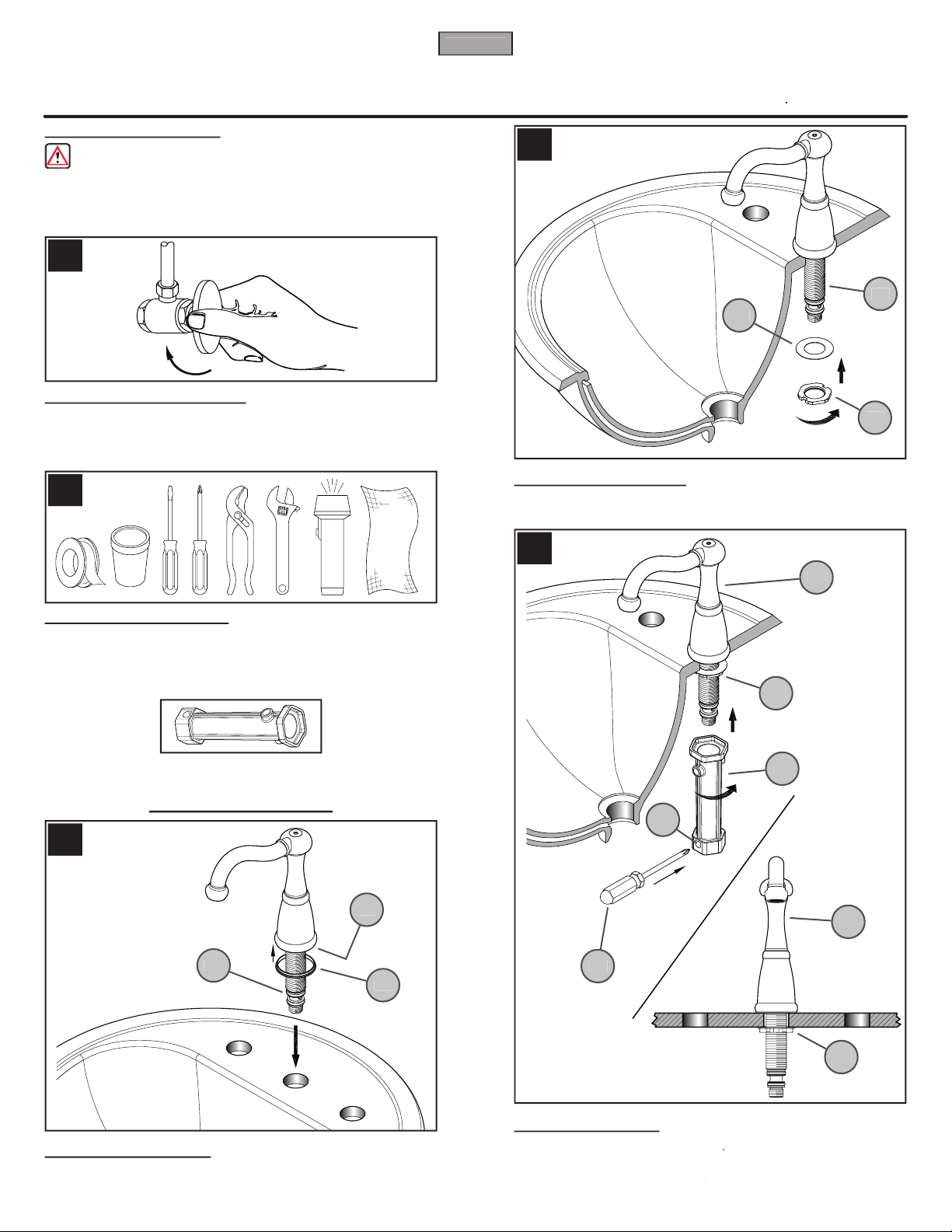
4 SPOUT ATTACHMENT
4A
) against the bottom of Spout Body (
4B
).
4C
) through the center hole of sink.
5 SPOUT INSTALLATION
) onto Spout Shank (
)
and tighten with Mounting Nut (
).
6 SECURING SPOUT
) by using Installation Tool (
).
) is centered and facing forward. For
), insert it through Hole (
) and tighten
the Mounting Nut (
) until Spout (
) is rmly secured to sink.
2
ENGLISH
4A
4C
5A
5B
5C
6A
6B
6C6D6A
6E
6E
3
5
6
4
Page 3
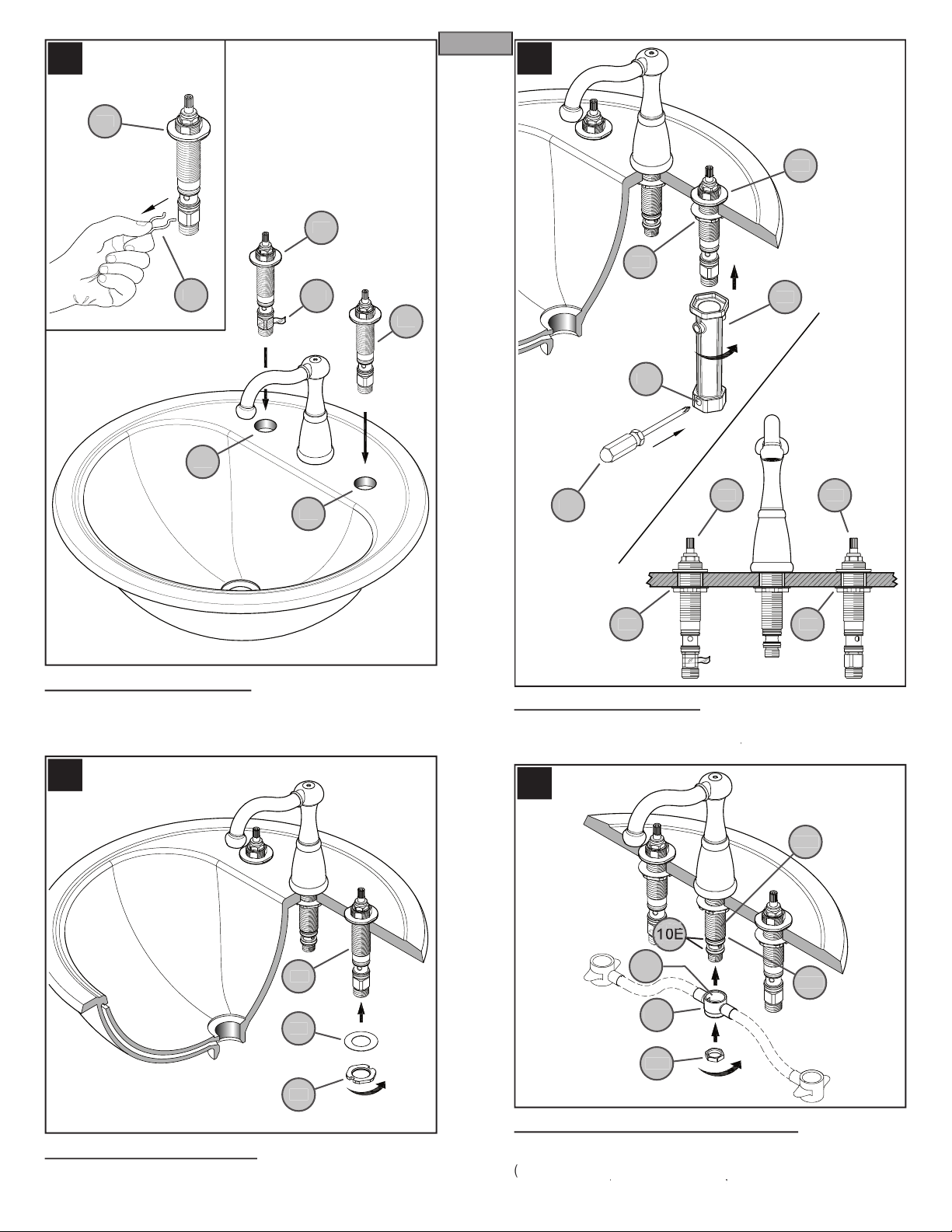
7 VALVE BODY ATTACHMENT
) from Valve Body (
) and save. From above sink, insert
Valve Body (
) through Mounting Holes (
). The HOT valve, labeled with
), should be positioned to the left side of the spout.
8 VALVE BODY INSTALLATION
) onto Valve Shank (
)
and tighten with Mounting Nut (
).
9 SECURING VALVE BODY
) by using Installation Tool (
).
), insert it through Hole (
) and
tighten the Mounting Nut (
) until Valve (
) is rmly secured to sink.
) onto Spout
Shank (
), push the Center Connector (
) up until the top of Socket
(
) reaches the Spout Shank Stop (
). Be careful not to damage the
O-Ring Seals (
). Thread Locknut (
).
7
ENGLISH
8A
8B
8C
9A9D9B
9C
9E
9E
9A
9A
9E
9
8
10
Page 4

) onto End Bodies (
). Tighten Mounting Nut (
) by
). For better leverage, use a Screwdriver (
),
) and tighten the Mounting Nut (
) until Center
Connector (
) is rmly secured to Spout Shank (
).
Thread Valve Adapters (
) onto the Valve Stems (
) and tighten so that
the Valve Adapters (
) sit on the surface of the Valve Body Washers (
).
) against the bottom of Handle Hubs (
).
Connect Handles (
) onto Valve Adapters (
).
Slide the End Connectors (
) onto the Valve Bodies (
). Push the End
Connectors (
) all the way up until completely seated. Be careful not to
damage O-Rings (
).
11
ENGLISH
12
13
14
Page 5

Valve function – COLD valve: close-counterclockwise, open-clockwise;
) in place and tighten the Hubs (
) by rotating them
) in a
counterclockwise direction.
Connect water Supply Lines (
) to Faucet Inlets (
). (Supply lines and
ttings are not included.)
) into hole at top of Spout Head (
). Gently, slide Lift
) down the Spout Head (
) hole.
) and unscrew Nut (
) from the Pop-Up Drain Body
(
). Retain the Packing Ring (
) inside the Ball Rod Opening (
).
Take off the Spring Clip (
) from the Ball Rod (
). Place the Nut (
)
on the Ball Rod (
). Remove Locknut (
), Friction Washer (
),
) and Stopper (
) from Flange (
).
16
ENGLISH
COLD
CLOSED
OPEN
CLOSED
OPEN
1815
19
17
Page 6

22 POP-UP ROD LINKAGE & ADJUSTMENT
22C
) on end of Ball Rod (
22B
). Insert Ball
) across and through hole in Pop-Up Strap (
). Secure other
end of Spring Clip (
22C
). Insert bottom of Lift Rod (
22A
) into hole at top of
). Tighten with Thumb Screw (
). Adjust Lift Rod
(
22A
) function by adjusting location of Thumb Screw (
22E
) along the
) or by adjusting the hole in which Ball Rod (
)
goes through the Pop-Up Strap (
). Be sure to leave enough space
22F
) and Spout Head (
22G
) when Lift Rod is down.
23 UNIT START UP
Turn on hot and cold water supplies, and check for leaks above and below
the sink
21 BALLROD ADJUSTMENT
21A
) into Drain Body (
21B
) from the top with the Off-Set
(
21C
) facing rear. From below, insert the Ball Rod (
) into the Ball Rod
Opening (
21E
) through the Stopper Hole (
21F
) and secure with Nut (
21G
).
20 POP-UP INSTALLATION
Apply a small bead of putty underneath the Flange (
20A
) and place a ring
of putty around Drain Opening (
20B
) of sink. Use PTFE plumber’s tape to
all threaded ttings according to manufacturer’s instructions. Insert Flange
(
20A
) into Drain Opening (
20B
). From underneath, insert Rubber Washer
(
20C
) and Friction Washer (
20D
) through the bottom of Flange (
20A
). Thread
20E
) until Rubber Washer (
20C
) seats securely inside Drain Opening
(
20B
). Thread Drain Body (
20F
) to bottom of Flange (
20A
). Hand tighten
and adjust the Drain Body so that the Ball Rod Opening (
20G
) faces the rear.
Wrench tighten Locknut (
20E
) and wipe excess putty.
20
ENGLISH
22C
22B
22D
22E
22F
22G
21A
21B
21C
21D
20A
20C
20D
20E
20F
20G
21G
22C
22A
22D
20B
22
21
23
Page 7

or visit www.pricep ster.com
2.
When replacement parts are not available, please write or
call Price P ster Consumer Service.
3.
Always turn off water and relieve pressure before
working on your faucet.
Cleaning Instructions:
cloth to clean and shine. Use of polish, detergents, abrasive
cleaners, organic solvents, or acid may cause damage.
other than a soft damp cloth will nullify our warranty!
Special Trim:
Trim products which contain porcelain or other similar
substances are not acceptable for public areas or commercial
24 FLUSHING & AERATOR CLEANING
To prevent damage to the internal parts of your faucet from debris that may
Turn on water supply valves.
After connections have been made, remove Aerator (
) and turn Handles
to the full “ON” position.
3.
Check for leaks, retighten where necessary, and let lines ush for one minute
without moving faucet handles. This will remove debris from lines which
can damage internal parts of faucet and cause leaks.
4.
After ushing, turn off handles and replace Aerator (
24A
).
To clean aerator, lift out Washer (
24B
) and Insert (
24C
) from Aerator Head
(
). Rinse parts and replace.
25 VALVE CARTRIDGE MAINTENANCE
Turn off water supplies and relieve pressure before working on your faucet
Remove Handles (
25A
)
25B
)
25C
) and inspect. Replace parts
as necessary.
26 HOSE CONNECTION MAINTENANCE
To detach Hose Assembly (
26A
), remove Clips (
26B
) from End Valve (
26C
)
and unscrew Locknut (
26D
) from Valve Stem (
26E
). Pull the Center Connector
(
26F
) and End Connectors (
26G
) down until Hose Assembly (
26A
) is free.
24
7
ENGLISH
24C
25A
25B
25C
26C
26B
26B
26D
26C
26E
26F
26G
26G
26A
26
25
Page 8

www.pricep ster.com
A COMPANY
A
Cromo Pulido
Chrome Poli
J
Oil Rubbed Bronze
931-009
910-025
COLD
950-025
950-200
931-600
931-940
971-019
972-019*
941-088*
910-024
CALIENTE
CHAUD
970-016
970-017
940-068*
941-087*
920-038*
949-004
900-024
COLD
900-023
CALIENTE
CHAUD
941-096
941-092*
970-016
970-017
950-025
950-200
931-600
49M Series
Lavatory Widespread Faucet
Grifo Extenso Para Baño
Robinet Sans Applique Pour Lavabo
 Loading...