

Page 1

Advertencia: Léase este instructivo antes de usar el producto.
Warning: Read instruction manual before using product.
Page 2
Page 3
Page 4
?
Page 5
Page 6

Page 7

Page 8

Page 9

Page 10

KG915
Voltaje AR, B2C, B2 220V
Voltaje B3, BR 120V/127V
5/8"-11 / M14
Page 11

ANGLE GRINDER KG915
E N G L I S H
CONGRATULATIONS!
You have chosen a Black & Decker tool. Our aim is
to provide quality tools at an affordable price.
We hope that you will enjoy using this tool for
many years.
INTENDED USE
Your Black & Decker angle grinder has been
designed for cutting metal and masonry using the
appropriate type of cutting or grinding disc.
It is also suitable for sanding using a backing pad
and sanding disc.
This tool is intended for consumer use only.
SAFETY INSTRUCTIONS
Warning symbols
The following symbols are used in this manual:
Denotes risk of personal injury, loss of life
or damage to the tool in case of
non-observance of the instructions in this
manual.
Denotes risk of electric shock.
Know your tool
Warning! When using mains-powered
tools, basic safety precautions,
including the following, should always
be followed to reduce the risk of fire,
electric shock, personal injury and
material damage.
Read all of this manual carefully before
operating the tool.
Before operating the tool, make sure
that you know how to switch the tool off
in an emergency.
Retain this manual for future reference.
Read the manual prior to operation.
Fire hazard.
11
Page 12

E N G L I S H
General
1. Keep work area clean
Cluttered areas and benches can cause accidents.
2. Consider work area environment
Do not expose the tool to rain. Do not use the
tool in damp or wet conditions. Keep the work
area well lit. Do not use the tool where there is
a risk of causing fire or explosion, e.g. in the
presence of flammable liquids and gases.
3. Keep children away
Do not allow children, visitors or animals to
come near the work area or to touch the tool
or mains cable.
4. Dress properly
Do not wear loose clothing or jewellery,
as these can be caught in moving parts.
Preferably wear rubber gloves and non-slip
footwear when working outdoors. Wear protective
hair covering to keep long hair out of the way.
5. Personal protection
Always use safety glasses. Use a face or dust
mask whenever the operations may produce
dust or flying particles. Wear ear protection
whenever the sound level seems uncomfortable.
6. Guard against electric shock
Prevent body contact with earthed or grounded
surfaces (e.g. pipes, radiators, cookers and
refrigerators). Electric safety can be further
improved by using a high-sensitivity
(30 mA / 30 mS) residual current device (RCD).
7. Do not overreach
Keep proper footing and balance at all times.
8. Stay alert
Watch what you are doing. Use common sense.
Do not operate the tool when you are tired.
9. Secure workpiece
Use clamps or a vice to hold the workpiece.
It is safer and it frees both hands to operate
the tool.
10.Connect dust extraction equipment
If devices are provided for the connection of
dust extraction and collection facilities, ensure
that these are connected and properly used.
11.Remove adjusting keys and wrenches
Always check that adjusting keys and wrenches
are removed from the tool before operating
the tool.
12
12.Extension cables
Before use, inspect the extension cable and
replace if damaged. When using the tool
outdoors, only use extension cables intended
for outdoor use.
13.Use appropriate tool
The intended use is described in this instruction
manual. Do not force small tools or attachments
to do the job of a heavy-duty tool. The tool will
do the job better and safer at the rate for
which it was intended. Do not force the tool.
Warning! The use of any accessory or attachment
or performance of any operation with this tool
other than those recommended in this instruction
manual may present a risk of personal injury.
14.Check for damaged parts
Before use, carefully check the tool and mains
cable for damage. Check for misalignment and
seizure of moving parts, breakage of parts,
damage to guards and switches and any other
conditions that may affect its operation.
Ensure that the tool will operate properly and
perform its intended function. Do not use the
tool if any part is damaged or defective.
Do not use the tool if the switch does not turn
it on and off. Have any damaged or defective
parts repaired or replaced by an authorised
repair agent. Never attempt any repairs yourself.
15.Unplug the tool
Unplug the tool when it is not in use, before
changing any parts of the tool, accessories or
attachments and before servicing.
16.Avoid unintentional starting
Do not carry the tool with a finger on the on/
off switch. Be sure that the tool is switched off
when plugging in.
17.Do not abuse cord
Never carry the tool by its cord or pull it to
disconnect from the socket. Keep the cord
away from heat, oil and sharp edges.
18.Store idle tools
When not in use, tools should be stored in
a dry, locked up or high place, out of reach of
children.
19.Maintain tools with care
Keep cutting tools sharp and clean for better
and safer performance. Follow the instructions
for maintenance and changing accessories.
Page 13

E N G L I S H
Keep handles and switches dry, clean and free
from oil and grease.
20.Repairs
This tool complies with relevant safety
requirements. Repairs should only be carried
out by qualified persons using original spare
parts; otherwise this may result in considerable
danger to the user.
Additional safety instructions for angle grinders
Wear safety glasses or goggles when
operating this tool.
Wear ear protection when operating this
tool.
Wear gloves when operating this tool.
Do not cut or grind light metal with a
magnesium content exceeding 80%,
since this type of metal is flammable.
Only use grinding and cutting discs and other
accessories recommended in this manual.
Make sure that the maximum speed of the
grinding or cutting disc exceeds the no-load
speed of the tool.
Do not cut workpieces requiring a maximum
depth of cut exceeding that of the cutting disc.
Never use the tool without the guard, except
for sanding.
Do not exert side pressure on the grinding or
cutting disc.
Use this tool only as a hand held tool.
- Do not let children or pregnant women enter
the work area.
- Do not eat, drink or smoke in the work area.
- Dispose of dust particles and any other
debris safely.
ELECTRICAL SAFETY
The electric motor has been designed for one
voltage only. Always check that the power supply
corresponds to the voltage on the rating plate.
This tool is double insulated in accordance
with EN 50144; therefore no earth wire is
required.
Using an extension cable
Always use an approved extension cable suitable
for the power input of this tool (see technical
data). Before use, inspect the extension cable for
signs of damage, wear and ageing. Replace the
extension cable if damaged or defective.
When using a cable reel, always unwind the cable
completely. Use of an extension cable not suitable
for the power input of the tool or which is damaged
or defective may result in a risk of fire and electric
shock.
PACKAGE CONTENTS
The package contains:
1 Angle grinder
1 Side handle
1 Grinding or cutting disc
1 Flange set
1 Two-pin spanner
1 Instruction manual
Sanding
Wear a dust mask whenever sanding.
Thoroughly remove all dust after sanding.
Take special care when sanding paint which is
possibly lead based or when sanding some
woods and metal which may produce toxic dust:
- Wear a dust mask specifically designed for
protection against lead paint dust and fumes
and ensure that persons within or entering
the work area are also protected.
Carefully unpack all parts.
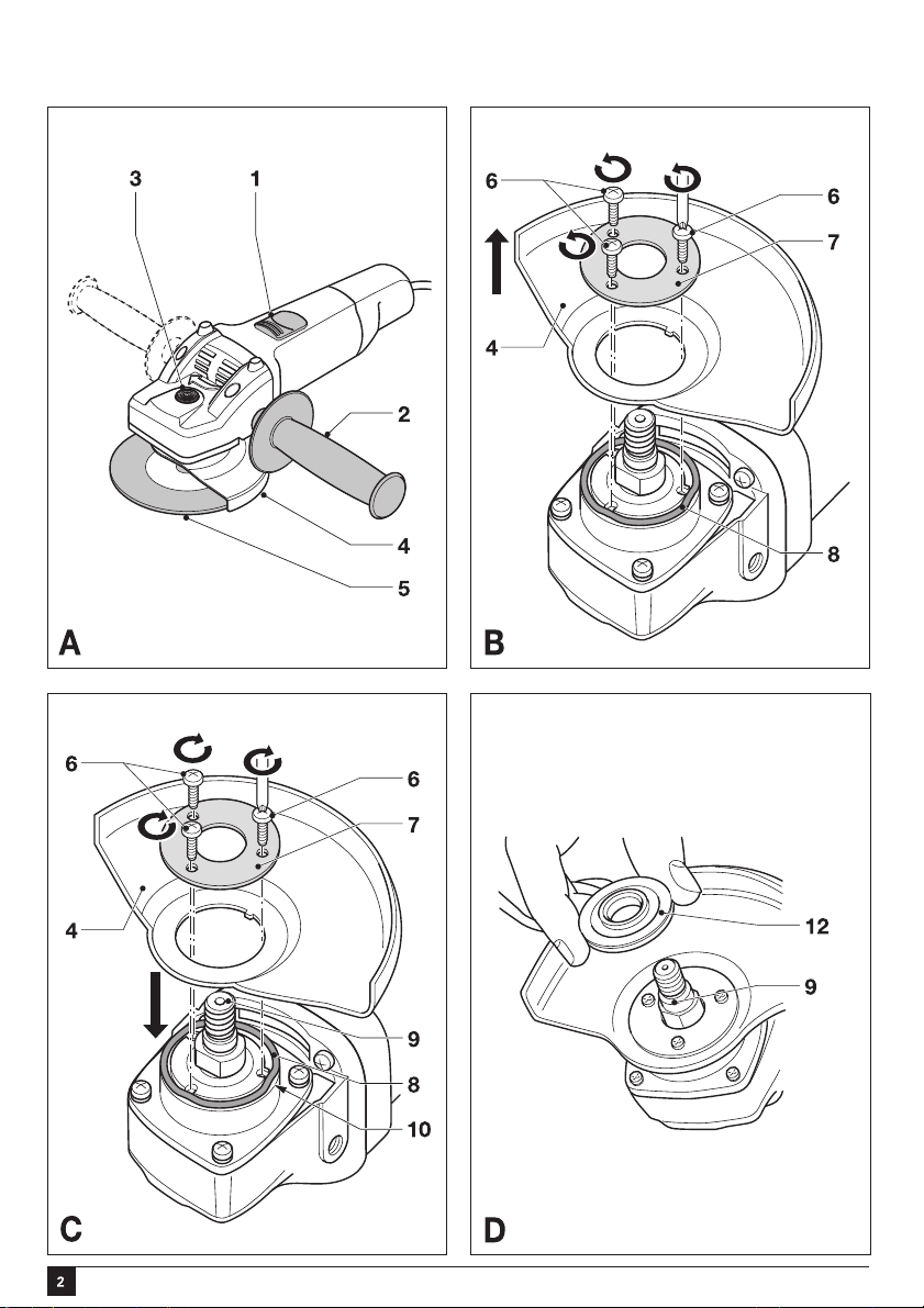
OVERVIEW (fig. A)
1. On/off switch
2. Side handle
3. Spindle lock
4. Guard
5. Grinding or cutting disc
13
Page 14

E N G L I S H
ASSEMBLY
Before attempting any of the following
operations, make sure that the tool is
switched off and unplugged and that the
disc has stopped rotating.
Removing and refitting of the guard
Never use the tool without the guard,
except when sanding.
Removing (fig. B)
This tool is fitted with a guard. For sanding only,
you can remove the guard as follows.
Remove the outer flange, disc and inner flange
as described below.
Use a screwdriver to remove the screws (6).
Remove the flange (7), guard (4) and spring
washer (8). Store these parts carefully.
Refitting (fig. C)
Place the tool on a table, with the spindle (9)
facing up.
Place the spring washer (8) over the spindle
and locate it on the shoulder (10).
Place the guard onto the tool as shown.
Place the flange (11) over the spindle with the
protruding pips towards the guard. Make sure
that the holes in the flange align with the screw
holes.
Secure the flange with the screws (6). Make sure
that the screws are fully tight and that the guard
can be rotated.
Fitting the side handle (fig. A)
Always use the side handle.
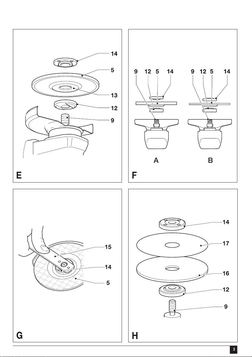
Fitting and removing grinding or cutting discs
(fig. A, D - G)
Always use the correct type of disc for
your application. Always use discs with the
correct diameter and bore size (see
technical data).
The maximum thickness for grinding discs
is 6 mm, for cutting discs 3.5 mm.
Fitting
If it has been removed, fit the guard as described
above.
Place the inner flange (12) onto the spindle (9)
as shown (fig. D). Make sure that the flange is
correctly located on the flat sides of the spindle.
Place the disc (5) onto the spindle (9) as shown
(fig. E). If the disc has a raised centre (13),
make sure that the raised centre faces the
inner flange.
Make sure that the disc locates correctly on the
inner flange.
Place the outer flange (14) onto the spindle.
When fitting a grinding disc, the raised centre
on the outer flange must face towards the disc
(A in fig. F). When fitting a cutting disc,
the raised centre on the outer flange must face
away from the disc (B in fig. F).
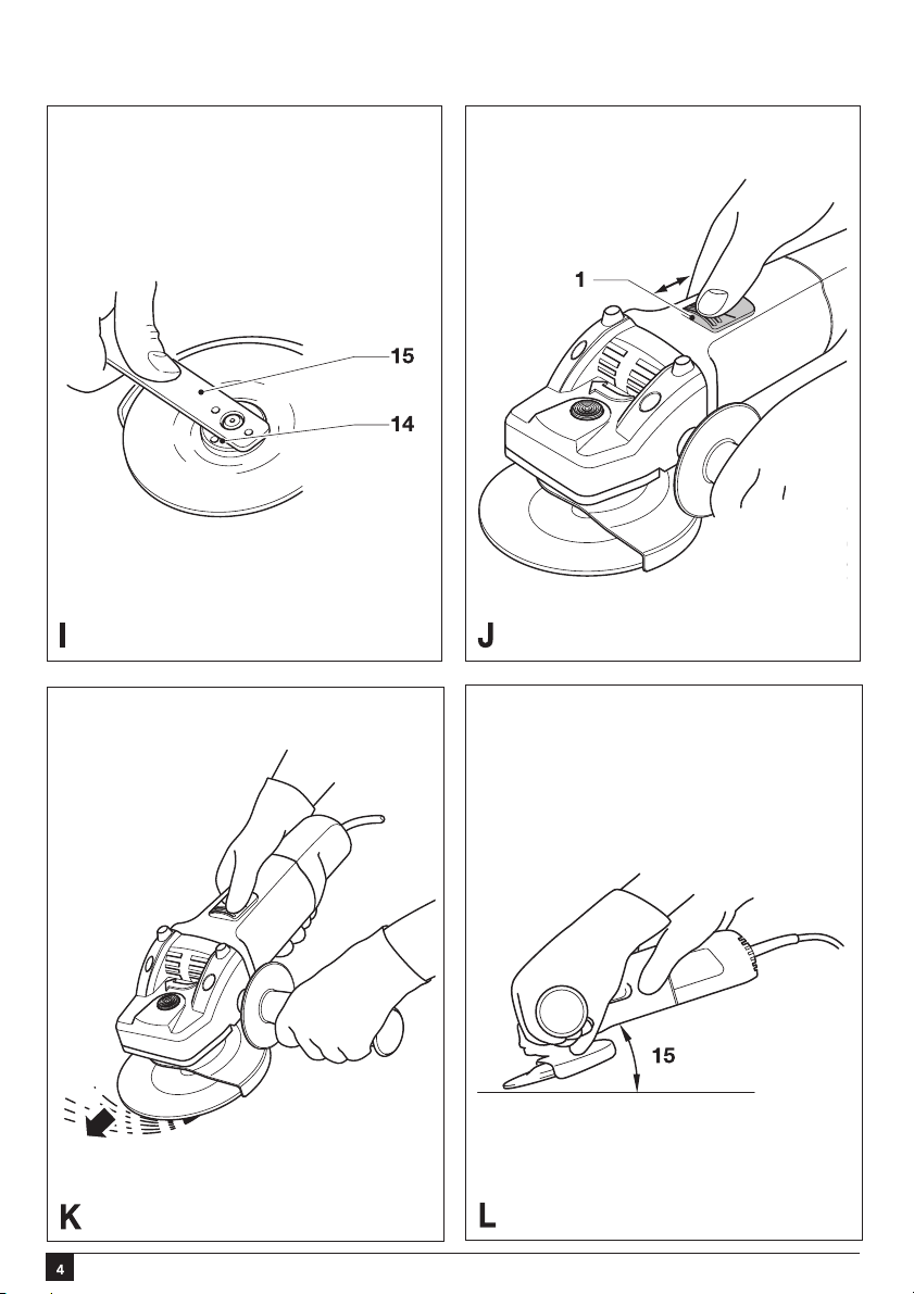
Keep the spindle lock (3) depressed and
tighten the outer flange using the two-pin
spanner (15) (fig. A & G). Make sure that the
outer flange is fitted correctly for the type of
disc used and that the disc is clamped tightly.
Removing
Keep the spindle lock (3) depressed and
loosen the outer flange (14) using the two-pin
spanner (15) (fig. A & G).
Remove the outer flange (14) and the disc (5).
Screw the side handle (2) into one of the
mounting holes in the tool.
14
Fitting and removing sanding discs (fig. A, H & I)
For sanding, a backing pad is required. The backing
pad is available from your Black & Decker dealer
as an accessory.
Page 15

E N G L I S H
Fitting
Remove the guard as described above.
Place the inner flange (12) onto the spindle (9)
as shown (fig. H). Make sure that the flange is
correctly located on the flat sides of the spindle.
Place the backing pad (16) onto the spindle.
Place the sanding disc (17) onto the backing
pad.
Place the outer flange (14) onto the spindle
with the raised centre facing away from the disc.
Keep the spindle lock (3) depressed and tighten
the outer flange using the two-pin spanner (15)
(fig. A & I). Make sure that the outer flange is
fitted correctly and that the disc is clamped
tightly.
Removing
Keep the spindle lock (3) depressed and
loosen the outer flange (14) using the two-pin
spanner (15) (fig. A & I).
Remove the outer flange (14), the sanding disc
(17) and the backing pad (16).
After sanding, refit the guard on the tool.
USE
Let the tool work at its own pace.
Do not overload.
Carefully guide the cable in order to avoid
accidentally cutting it.
Be prepared for a stream of sparks when the
grinding or cutting disc touches the workpiece.
Always position the tool in such a way that the
guard provides optimum protection from the
grinding or cutting disc.
Hints for optimum use
Firmly hold the tool with one hand around the
side handle and the other hand around the
motor housing (fig. K).
When grinding, always maintain an angle of
approx. 15° between the disc and the workpiece
surface (fig. L).
MAINTENANCE
Your Black & Decker tool has been designed to
operate over a long period of time with a
minimum of maintenance. Continuous satisfactory
operation depends upon proper tool care and
regular cleaning.
Before performing any maintenance,
switch off and unplug the tool.
Regularly clean the ventilation slots in your tool
using a soft brush or dry cloth.
Regularly clean the motor housing using a
damp cloth. Do not use any abrasive or
solvent-based cleaner.
You can check the location of your nearest
authorized repair agent by contacting your local
Black & Decker office at the address indicated in
this manual.
Technical data
KG915
Voltage AR, B2, B2C 220V
Voltage B3, BR 120V/127V
Power input W 900
No-load speed min-110,000
Disc diameter mm 115
Disc bore mm 2
5/8"-11 / M14ezis eldnipS
1.2gkthgieW
Wear safety glasses or goggles when
operating this tool.
Switching on and off (fig. J)
To switch on, slide the on/off switch (1)
forward. Note that the tool will continue
running when you release the switch.
To switch off, press the rear part of the on/off
switch.
15
Page 16

Solamente para propósito de Argentina:
Importado por: Black & Decker Argentina S.A.
Pacheco Trade Center
Colectora Este de Ruta Panamericana
Km. 32.0 El Talar de Pacheco
Partido de Tigre
Buenos Aires (B1618FBQ)
República de Argentina
No. de Importador: 1146/66
Tel. (011) 4726-4400
Imported by/Importado por:
Black & Decker do Brasil Ltda.
Rod. BR 050, s/n° - Km 167
Dist. Industrial II
Uberaba ˆ MG ˆ Cep: 38064-750
CNPJ: 53.296.273/0001-91
Insc. Est.: 701.948.711.00-98
S.A.C.: 0800-703-4644
Solamente para propósitos de CCA
Importado por: Black & Decker LLC
Calle Miguel Brostella Final
Edificio Milano I, Mezanine 5,6 y 7
El Dorado, Panama
Tel. 507-360.5700
Solamente para propósitos de Colombia
Importado por: Black & Decker de Colombia, S.A.
Carrera 85D # 51-65, Bodega 23
Complejo Logístico San Cayetano
Bogota - Colombia
Tel. 744-7100
Solamente para propósito de Chile:
Importado por: Black & Decker de Chile, S.A.
Av. Pdte. Eduardo Frei M. 6001-67 Conchalí
Santiago de Chile
Tel. (56-2) 687 1700
Solamente para propósito de México:
Importado por: Black & Decker S.A. de C.V.
Bosques de Cidros, Acceso Radiatas No.42
3a. Sección de Bosques de las Lomas
Delegación Cuajimalpa,
05120, México, D.F.
Tel. (52) 555-326-7100
R.F.C.: BDE810626-1W7
Black & Decker del Perú S.A.
Av. Enrique Meiggs 227.
Pque. Industrial - Callao
Teléfono: (511) 452-5577
RUC 20266596805
Impreso en China
Printed in China
478306-00
09/14/07
16
 Loading...