

Page 1
BIACK&DEGKER
#
NO. 3027-09 & 3027-90
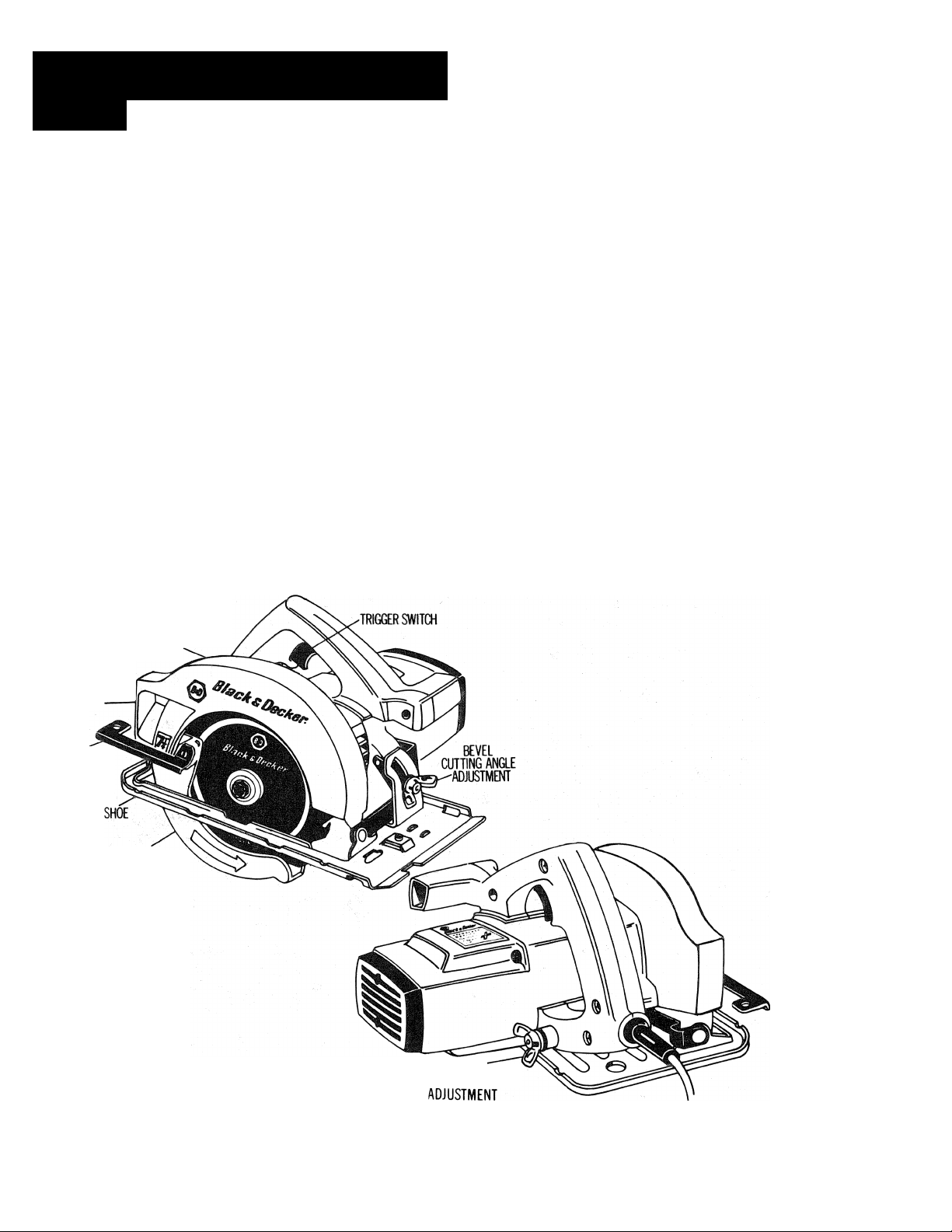
7V4" SAWCAT® CIRCULAR SAW
Featuring:
1) Double Insulated construction with 3-wire, grounding 10 foot rubber power
cord.
2) Motor brushes are easily serviced.
3) Good visibility of blade and cutting line from operating position. Adjustable
cutting guide.
4) Rolled edge on shoe facilitates using guide strip for accurate cutting.
5) Knobs control bevel and cutting depth adjustments.
6) Enclosed lower guard return spring. Separate, removable switch handle, if re
placement ever needed.
MAXIMUM CUTTING DEPTH at 90°—2yu"; at 45°—1%"
120 Volts, 10 Amps. 5500 R.P.M.
STATIONARY
UPPER BLADE
GUARD
SMXJST
EJECTW
CHUTE
LEVER FOR
RETRACTIf«
LOWER BLADE
OJARD
LOWER
BLADE
GUARD
CUTTING-
DEPTH
INSTRUCTION MANUAL
Page 2

IMPORTANT SAFETY INSTRUCTIONS
WARNING; When using Electric Tools, basic safety precautions should always be
followed to reduce risk of fire, electric shock, and personal injury, including the following:
READ ALL INSTRUCTIONS
1. KEEP WORK AREA CLEANXIuttered areas and benches invite injuries.
2. CONSIDER WORK AREA ENVIRONMENT. Don’t expose power tools to rain. Don’t
use power tools in damp or wet locations. Keep work area well lit.
3. GUARD AGAINST ELECTRIC SHOCK. Prevent body contact with grounded surfaces.
For example: pipes, radiators, ranges, refrigerator enclosures.
4. KEEP CHILDREN AWAY. All visitors should be kept away from work area. Do not let
visitors contact tool or extension cord.
5. STORE IDLE TOOLS. When not in use, tools should be stored in dry, and high or
locked-up place—out of reach of children.
6. DON’T FORCE TOOL. It will do the job better and safer at the rate for which it was
intended.
7. USE RIGHT TOOL. Don’t force small tool or attachment to do the job of a heavy-duty
tool. Don’t use tool for purpose not intended, for example, don’t use circular saw for
cutting tree limbs or logs.
8. DRESS PROPERLY. Do not wear loose clothing or jewelry. They can be caught in
moving parts. Rubber gloves and non-skid footwear are recommended when working
outdoors. Wear protective hair covering to contain long hair.
9. USE SAFETY GLASSES. Also use face or dustmask if cutting operation is dusty.
10. DON’T ABUSE CORD. Never carry tool by cord or yank it to disconnect from
receptacle. Keep cord from heat, oil, and sharp edges.
11. SECURE WORK. Use clamps or a vise to hold work. It’s safer than using your hand
and it frees both hands to operate tool.
12. DON’T OVERREACH. Keep proper footing and balance at all time-.
13. MAINTAIN TOOLS WITH CARE. Keep tools sharp and clean for better and safe
performance. Follow instructions for lubricating and changing accessories. Inspect
tool cords periodically and if damaged have repaired by authorized service facility. In
spect extension cords periodically and replace if damaged. Keep handles dry, clean,
and free from oil and grease.
14. DISCONNECT TOOLS. When not in use, before servicing, and when changing
accessories, such as blades, bits, cutters.
15. REMOVE ADJUSTING KEYS AND WRENCHES. Form habit of checking to see that
keys and adjusting wrenches are removed from tool before turning it on.
16. AVOID UNINTENTIONAL STARTING. Don’t carry plugged-in tool with finger on
switch. Be sure switch is off when plugging in.
17. OUTDOOR USE EXTENSION CORDS. When tool is used outdoors, use only extension
cords intended for use outdoors and so marked.
Page 3

18. STAY ALERT. Watch what you are doing. Use common sense. Do not operate tool
when you are tired.
19. CHECK DAMAGED PARTS. Before further use of the tool, a guard or other part that
is damaged should be carefully checked to determine that it will operate properly and
perform its intended function. Check for alignment of moving parts, binding of mov
ing parts, breakage of parts, mounting, and any other conditions that may affect its
operation. A guard or other part that is damaged should be properly repaired or
replaced by an authorized service center unless otherwise indicated elsewhere in
this instruction manual. Have defective switches replaced by Authorized Service
Center. Do not use tool if switch does not turn it on and off.
20. DO NOT OPERATE portable electric tools near flammable liquids or in gaseous or
explosive atmospheres. Motors in these tools normally spark, and the sparks might
ignite fumes.
CIRCULAR SAW SAFETY INSTRUCTIONS
1. Disconnect plug from power supply before changing blades, making cutting depth or
cutting angle adjustments, inspecting, cleaning or when saw is not used.
2. Keep guards in place and in working order. Never wedge or tie lower guard open.
Check operation of lower guard before each use. Do not use if lower guard does not
close briskly over saw blade. CAUTION : If saw is dropped, lower guard may be bent,
restricting full return.
3. KEEP BLADES CLEAN AND SHARP. Sharp blades minimize stalling and kick back.
4. DANGER: KEEP HANDS AWAY FROM CUTTING AREA. (See fig. 7) Keep hands away
from blades. Do not reach underneath work while blade is rotating. Do not attempt to
remove cut material when blade is moving. CAUTION: Blades coast after turn off.
5. SUPPORT LARGE PANELS. Large panels must be supported as shown in FIGURE 8
tominimizethe risk of blade pinching and kick back. When cutting operation requires
the resting of the saw on the work-piece, the saw shall be rested on the larger portion
and the smaller piece cut off. (See FIGURE 7)
6. USE RIP FENCE. Always use a fence or straight edge guide when ripping.
7. GUARD AGAINST KICK BACK. Kick back occurs when the saw stalls rapidly and is
driven back towards the operator. Release switch immediately if blade binds or saw
stalls. Keep blades sharp. Support large panels as shown in FIGURE 8. Use fence or
straight edge guide when ripping. Don’t force tool. Stay alert, exercise control. Don’t
remove saw from work during a cut while the blade is moving.
8. LOWER GUARD. Raise lower guard with the retracting handle.
9. ADJUSTMENTS. Before cutting be sure depth and bevel adjustments are tight.
10. USE ONLY CORRECT BLADES IN MOUNTING. Do not use blades with incorrect size
holes. Never use defective or incorrect blade washers or bolts.
11. AVOID CUTTING NAILS. Inspect for and remove all nails from lumber before cutting.
SAVE THESE INSTRUCTIONS
Page 4

GROUNDING
This tool should be grounded while in use to protect the operator from electric
shock. The tool is equipped with an approved three-conductor cord and threeprong grounding type plug to fit the proper grounding type receptacle. The green
(or green and yellow) conductor in the cord is the grounding wire. Never connect
the green (or green and yellow) wire to a live terminal.
If your unit is for use on less than 150 volts, it has a plug like that shown in
Figure A. If it is for use on 150 to 250 volts, it has a plug like that shown in Figure
D. An adapter. Figures B and C, is available for connecting Figure A plugs to twoprong receptacles. The green-colored rigid ear, lug, etc., must be connected to a
permanent ground such as a properly grounded outlet box.
No adapter is available for a plug as shown in Figure D. Adapter shown in Figures
B & C is Not for Use in Canada.
GROUNDED OUTLET BOX ^
^ ADAPTER
©
GROUNDING
PRONG IS
LONGEST OF
THE 3 PRONGS
We recommend that you NEVER disassemble the tool or try to do any rewiring in
the electrical system. Any repairs should be performed only by B&D Service Cen
ters or other qualified service organizations. Should you be determined to make a
repair yourself, remember that the green colored wire is the “grounding” wire.
Never connect this green wire to a “live” terminal. If you replace the plug on the
power cord, be sure to connect the green wire only to the grounding (longest)
prong on a 3-prong plug, THESE INSTRUCTIONS
(0)
©
A. B. C. D.
GROUNDED
OUTLET BOX ^
( GROUNDING
MEANS
GROUNDED OUTLET BOX ^
©
m
GROUNDING
PRONG IS
LONGEST OF
THE 3 PRONGS
/
©
EXTENSION CORDS
Tools that have 3 wire cords requiring grounding must only be used with extension cords
that have 3-prong grounding type plugs and 3-pole receptacles. Only round jacketed
extension cords should be used, and we recommend that they be listed by Underwriters
Laboratories (U.L) (C.S.A. in Canada). If the extension will be used outside, the cord must be
suitable for outdoor use. Any cord marked as outdoor can also be used for indoor work.
An extension cord must have adequate wire size (AWG or American Wire Gauge) for
safety, and to prevent loss of power and overheating. The smaller the gauge number of
the wire, the greater the capacity of the cable, that is 16 gauge has more capacity than 18
gauge. When using more than one extension to make up the total length, be sure each
individual extension contains at least the minimum wire size.
To determine the minimum wire size required, refer to the chart below:
CHART FOR MINIMUM WIRE SIZE (AWG) OF EXTENSION CORDS
NAMEPUtTE
IÀTING-AMPS 25
0 -10.0
10.1 -13.0 16
13.1 -15.0
Before using an extension cord, inspect it for loose or exposed wires, damaged insulation,
and defective fittings. Make any needed repairs or replace the cord if necessary. Black &
Decker has extension cords available that are U.L (C.SA in Canada) listed for outdoor use.
18 18 16
14 14 12 12
50 75 100 125
16
MOTOR
Your Black & Decker tool is powered by a B & D-built motor. Be sure your power
supply agrees with the nameplate marking.
Volts 50/60 Hz or “AC only” means your tool must be operated only with alter
nating current and never with direct current. Volts DC-60Hz or AC/DC means your
tool may be operated with either alternating or direct current.
Voltage decrease of more than 10% will cause loss of power and over-heating. All B&D
tools are factory-tested; if this tool does not operate, check the power supply.
TOTAL EXTENSION CORD LENGTH ■ FEET
150 175
14 14 14 12
16
14
12 12
14 12
12
12
200
12
12
—
Page 5

MAINTENANCE
It is recommended that, once a year, you take or send the tool to a B&D Service
Center for a thorough cleaning, inspection and lubrication of the gear case. Service
Center addresses are shown on the owner registration card packed with your tool.
RETRACTING
LEVER
FIGURE 1
MOlfITING
HOLE
SCREW WASHER
CLAMPING
SCREW OUTER CLAMP
WASHER
FIGURE 2
ATTACHING & REMOVING BLADES
1. BE SURE SAW IS DISCONNECTED FROM POWER SUPPLY!
2. To remove blade clamping screw (Fig. 1):
—a. ON NEW SAWS (without blade attached). Turn screw counter-clockwise with
blade wrench provided. If screw does not loosen easily from spindle, tap the outer
end of the wrench sharply in a counter-clockwise direction with a piece of wood
to "free” the screw threads. Remove screw and outer clamp washer.
—b. ON SAWS WITH BLADE ATTACHED. Using the retracting lever, retract the
lower blade guard and place the Saw on a piece of scrap lumber as shown in
Figure 2. Press down on the Saw so that the blade teeth dig slightly into the lum
ber and prevent the blade from turning. Then, with the blade wrench provided,
turn the clamping screw counter-clockwise and remove the screw and outer clamp
washer. Disengage the blade teeth from the lumber, and with the lower blade
guard still retracted, lift off the blade.
3. To attach the blade: Place inner clamp washer on spindle if previously re
moved. Retract lower blade guard and place blade over inner clamp washer with
printed side of blade out (teeth at bottom of blade pointing forward). Fit outer
clamp washer onto spindle . . . “flats” on the outer washer must mesh with the
“flats” on the spindle. Thread on clamping screw firmly by hand to hold washers
in position. Place Saw on piece of scrap lumber as shown in Figure 2 and press
down on the Saw so that blade teeth dig slightly into wood and prevent the blade
from turning. Tighten clamping screw (clockwise) firmly with the blade wrench.
NOTE: An alternate way to keep the blade from turning, when tightening or loosen
ing the blade screw, is to hold a large nail through the hole in the blade and
against the forward part of the shoe. Rest the nail on top of the shoe when tight
ening, against the bottom when loosening. CAUTION: Remove nail before con
necting plug.
Page 6

FIGURE 3
CUTTING DEPTH ADJUSTMENT
DISCONNECT PLUG FROM POWER SUPPLY BEFORE MAKING THIS OR ANY
OTHER ADJUSTMENT.
For the most efficient cutting action, set the Depth Adjustment so that one tooth
of the blade will project below the material to be cut. This distance is from the
tip of the tooth to the bottom of the gullet in front of it. This keeps blade friction
at a minimum, removes sawdust from the cut, and results in cooler, faster sawing.
NOTE; When using Carbide-Tipped Blades, make an exception to the above rule
and allow only one-half of a tooth to project below the material being cut.
To adjust the cutting depth:
1. BE SURE THE SAW IS DISCONNECTED FROM THE POWER SUPPLY!
2. Place the saw in the position shown in Figure 3 and loosen depth adjustment
knob ‘‘A".
3. Place a scrap piece of the material to be cut along the side of the blade as
shown. Raise or lower the shoe until the blade projects from the shoe the
desired distance. Retighten knob.
SWITCH
Pull the trigger switch to turn the motor “ON". Releasing the trigger instantly
turns the motor "OFF”. For safer operation, this tool has no provision to lock
the switch in the “ON” position.
6
Page 7

FIGURE 4
BEVEL ANGLE ADJUSTMENT
DISCONNECT THE SAW FROM THE POWER SUPPLY BY PULLING THE PLUG,
BEFORE MAKING THIS, OR ANY OTHER ADJUSTMENT! On the front of the saw
is a bevel angle adjustment device (Figure 4) consisting of calibrated quadrant
“E” and a knob “D”. To set the saw for a bevel cut, loosen knob and tilt shoe
to angle desired. Retighten knob firmly.
CAUTION: When making bevel cuts, place one hand on the motor housing as
shown in Figure 4. Exert only enough pressure in the direction of the arrow to
keep the saw shoe flat on the work. This will insure an accurate bevel cutting
angle and help prevent the blade from binding in the cut.
GUIDE ALONG PENCILLED GUTTING LINE
SO KERF FALLS IN WASTE STOCK —
GUIDE EDGES
Guide along the penciled cut
ting line so that the kerf falls
into the waste or surplus
material—See Figure 5.
An Adjustable Guide on
the front of the saw
shoe has two guide
edges (Figure 6)—one
for vertical cutting, and
one for 45‘’bevel cut
ting. These edges en
able you to guide the
saw along penciled lines,
and the edges line up
with the left (inner) side
of the saw blade. This
makes the slot or "kerf"
cut by the moving blade
fall to the right of the
guide mark.
DESIRED
- LENGTH -
OF STOCK
WASTE
SURPLUS
-KERF
OR
STOCK
FIGURE 5
45* BEVEL CUT 1 GUIDE
0* VERTICAL CUTJ EDGES
FIGURE 6
Page 8

OPERATION
Figure 7 shows proper sawing
position. Note that hands are
kept away from cutting area,
safety glasses are worn, power
cord is kept clear of cutting
area and positioned so that it
will not be caught on the work
piece while cutting and that
clothing is not loose to the point
where it might get caught in
moving parts.
When operating the saw, keep
the cord away from the cutting
area and prevent it from becom
ing hung up on the work piece.
WARNING: It is impor
tant to support the work
properly and to hold the
saw firmly to prevent
loss of control which
could cause personal in
jury. Figure 7 illustrates
typical hand support of
the saw.
TO AVOID KICKBACK. DO
SUPPORT BOARD OR
PANEL NEAR THE CUT.
FIGURE 8
8
Page 9

OPERATION
WARNING: It is important to support the work properly and to hold the saw
firmly to prevent loss of control which could cause personal injury.
ALWAYS DISCONNECT SAW BEFORE MAKING ANY ADJUSTMENTS! Place the work
with its "good” side—the one on which appearance is most important—down.
The saw cuts upward, so any splintering will be on the work face that is up when
you saw it.
Support the work so that the cut will be on your right. Place the wider portion of
the saw shoe on that part of the work piece which is solidly supported, not on the
section that will fall off when the cut is made. As examples. Figure 9 illustrates
the RIGHT way to cut off the end of a board, and Figure 10 the WRONG way. If
the work is short or small, clamp it down. Don't try to hold short pieces by hand!
FIG. 9 -RIGHT
Draw the required guide lines. Then rest the front of the saw shoe on the work
with the guide edge lined up with the drawn guide line. Before starting the motor,
push the blade lightly against the edge of the work and then back off about
Now, start the motor, and when the blade gains full speed, push the saw forward
and begin sawing. As you begin cutting, the lower blade guard will automatically
begin to telescope into the upper blade guard. This telescoping action will continue
as you advance the saw until it reaches the position in Figure 9
Push the saw forward at a speed which allows the blade to cut without laboring.
Hardness and toughness can vary even in the same piece of material, and a
knotty or damp section can put a heavy load on the saw. When this happens, push
the saw more slowly, but hard enough to keep it working without much decrease
in speed. Forcing it beyond this makes for rough cuts, inaccuracy and overheating
of the motor.
Should your cut begin to go off the line, don’t try to force the saw back on. Re
lease trigger and allow blade to come to a complete stop. Then you can withdraw
the saw, sight anew, and start a new cut a trifle inside the wrong one. In any
event, withdraw the saw if you must shift the cut. Forcing a correction inside the
cut can stall the saw and perhaps spoil the work. IF SAW STALLS, RELEASE THE
TRIGGER, BACK THE SAW UNTIL IT IS LOOSE. BE SURE BLADE IS STRAIGHT IN
THE CUT BEFORE RESTARTING.
As you finish a cut, release the trigger and allow the blade to stop before lifting
the saw from the work. As you lift the saw the spring-tensioned telescoping guard
will automatically close under the saw. Remember the blade is exposed until this
occurs; never reach under the work for any reason whatsoever. When you have to
retract the telescoping guard manually (as is necessary for starting pocket cuts)
always use the retracting lever.
FIG. 10 - WRONG
Page 10

FIGURE 11
POCKET CUTTING
DISCONNECT SAW FROM POWER SUPPLY BEFORE MAKING CUTTING DEPTH
ADJUSTMENT! Set blade to desired cutting depth. Tilt saw forward and rest
front of shoe on material to be cut. Using the retracting lever, retract blade guard
to an upward position. Lower rear of shoe until blade teeth almost touch cutting
line. Now release the blade guard and its contact with the work will keep it in
position to open freely as you start the cut (Figure 11). Start the motor and
gradually lower the saw until its shoe rests flat on the material to be cut. Advance
saw along cutting line until cut is completed. Release trigger and allow blade to
stop completely before withdrawing the blade from the material. When starting
each new cut, repeat as above. Never tie the blade guard in a raised position.
ACCESSORIES
The accessories listed in this manual are available at extra cost from your local dealer
or Black & Decker Service Center. A complete listing of service centers is included
on the owner’s registration card packed with your tool.
If you need assistance in locating any accessory, please contact: Black & Decker (U.S.)
Inc., User Services Department, 10 North Park Drive, P.O. Box 857, Hunt Valley,
MD 21030-0857.
RIP FENCE. . . Attaches to top of Saw shoe. Permits rip
cuts without penciled guide lines.
B. SAW PROTRACTOR. . . Guides Saw for accurate cut-off
work. Adjusts from 0° to 70°.
CUT-OFF GUIDE. . For 90° or 45° cuts.
SAFETY GLASSES. . . Lightweight, one-piece, impact resis
tant, clear plastic safety glasses with side shields. Can be
worn directly over eyes or over prescription glasses.
Comfortable.
SAW CARRYING CASE
handy on the job.
CAUTION: Recommended accessories and saw blades for your Saw are listed
above and on the next page of this manual. The use of any other type of blade
or accessory might be hazardous.
. Protect your saw, keep saw accessories and extra blades
10
Page 11

BLACK & DECKER CIRCULAR SAW BLADES
A dull blade will cause slow, inefficient cutting and will overload the saw motor. It is a
good practice to keep extra blades on hand so that sharp blades are available while the dull
ones are being sharpened (See "SAWS—SHARPENING" in Yellow Pages). In fact, many lower
priced blades can be replaced with new ones at very little cost over the sharpening price. USE
ONLY 71/4", 7%" or 7" BLADES, WITH %" ARBOR HOLE, ON YOUR SAW.
Hardened gum on the blade will slow down the cutting. This gum can best be removed with
trichlorethylene, kerosene or turpentine. Remove blade before cleaning to prevent solvent from
damaging plastic parts of saw.
Black & Decker manufactures a complete line of saw blades and the following types are
available.
Standard; Outstanding value for the price. These blades are also available in bulk quantities.
Ask for quantity prices. (When sold in bulk, "-01" is added to catalog number).
Premium: Industrial chrome plating gives twice the cutting life of unplated blades.
TYPE OF BLADE
COMBINATION Chisel tooth configuration means this
blade is the fastest cutting blade in our line. Specifically
designed for general-purpose ripping and cross-cutting
where the finish of the cut is not critical.
FRAMING/RIP An all-purpose blade for smooth, fast
cutting in any direction. Rips, crosscuts, miters, etc.
Gives especially fast, smooth finishes when cutting with
the grain of both soft and hard woods.
METAL CUTTING Teeth shaped and set specifically for
cutting aluminum, copper, lead and other soft metals.
HOLLOW GROUND PLANER Specially ground for
satin-smooth finish cuts (cross-cuts, rips and miters) In
all solid woods. A professional quality blade for use In
cabinet work, furniture, etc. Specifically designed to
make extremely smooth cuts in wood.
CARBIDE TIPPED (8 tooth) Specially designed for cut
ting tough-to-cut materials such as: Transite, Cemesto
board, asbestos, Formica and Masonite. Will also cut
wood where speed and finish are not critical.
CARBIDE TIPPED (20 tooth) Chisel tooth combination
blade for fast general-purpose cutting in all types of
woods. Tips are of tungsten carbide material which out
lasts regular steel blades up to 10 to 1. Teeth are accu
rately set for ease of cutting.
TOOTH
SHAPE
>
FLOORING For use where nails or other metal objects
may be encountered, such as cutting reclaimed lumber,
flooring, opening crates. Allows crosscuts as well as
miters.
HOLLOW GROUND PLYWOOD Special taper grinding
on the sides of this thin-rim blade gives an absolutely
smooth cut in plywood, veneers and laminates, etc. Can
be used in crosscutting and mitering for a professional
finish on ail types of cabinet work.
STEEL CUTTING FRICTION Designed for cutting cor-
rugated or sheet roofing, black Iron, furnace pipe or
thin bar stock. Cuts faster with less filings than abra
sive blades. Cuts by friction action.
CROSS-CUT Specifically designed for smooth, fast cut
ting cross the grain of both hard and soft woods where
finish is an Important factor. May also be used for rip
and crosscuts on extremely hard woods.
ABRASIVE BLADES (Fiberglass Reinforced)
Aluminum Oxide cuts ferrous
metals and hardened non-ferrous
metals.
11
rry
Silicon Carbide cuts masonry
materials and soft non-ferrous
metals.
Page 12

CLEANING
Use only mild soap and a damp cloth to clean the tool. Many household cleaners
contain chemicals which could seriously damage the plastic. Also, do not use
gasoline, turpentine, lacquer or paint thinner, dry cleaning fluids or similar prod
ucts. Never let any liquid get inside the tool; never immerse any part of the tool
into a liquid.
IMPORTANT
To assure product SAFETY and RELIABILITY, repairs, maintenance and adjustment
(including brush inspection and replacement) should be performed by Black &
Decker Service Centers or other qualified service organizations, always using
Black & Decker replacement parts. When servicing Double-Insulated Tools, it is
extremely important that ONLY IDENTICAL REPLACEMENT PARTS BE USED and
that REASSEMBLY OF TOOL IS IDENTICAL TO THE ORIGINAL ASSEMBLY.
COMMERCIAL/INDUSTRIAL USE WARRANTY
Black & Decker (U.S.) Inc. warrants this product for one year from date of pur
chase. We will repair without charge, any defects due to faulty material or
workmanship. Please return the complete unit, transportation prepaid, to any
Black & Decker Service Center or Authorized Service Station listed under “Tools
Electric” in the yellow pages. This warranty does not apply to accessories or
damage caused where repairs have been made or attempted by others.
Like all Black & Decker tools, your Saw is listed by Underwriters’ Laboratories to en
sure that it meets stringent safety requirements.
This symbol on the nameplate means the product
is Listed by Underwriters' Laboratories, Inc,
See Tools-Electric’
7\
—Yellow Pages—
for Service & Sales
BLACK & DECKER (U.S.) INC.
U.S. Power Tools Group • 10 North Park Drive
P.O. Box 798 • Hunt Valley, MD 21030-0798
Form No. 740565-03
(AUG86-CD)
©1982 Printed in U.S.A.
 Loading...