

Page 1

Black & Decker (U.S.) Inc. • 701 East Joppa Road, Towson, Maryland 21286
Printed in U.S.A. (AUG96-CD-1) Form No. 154577 Copyright © 1996
154577/2683-220 IC 5/17/02 1:47 PM Page 2
Page 2

Instruction Manual
2683-220
Circular Saw
154577/2683-220 IC 5/17/02 1:47 PM Page 3
Page 3
1
Getting the most out of your tool.
Please take time to read this manual and pay particular attention to the
safety rules we've provided for your protection. If you have any questions
about your tool please call:
1-800-9-BD TOOL
(1-800-923-8665)
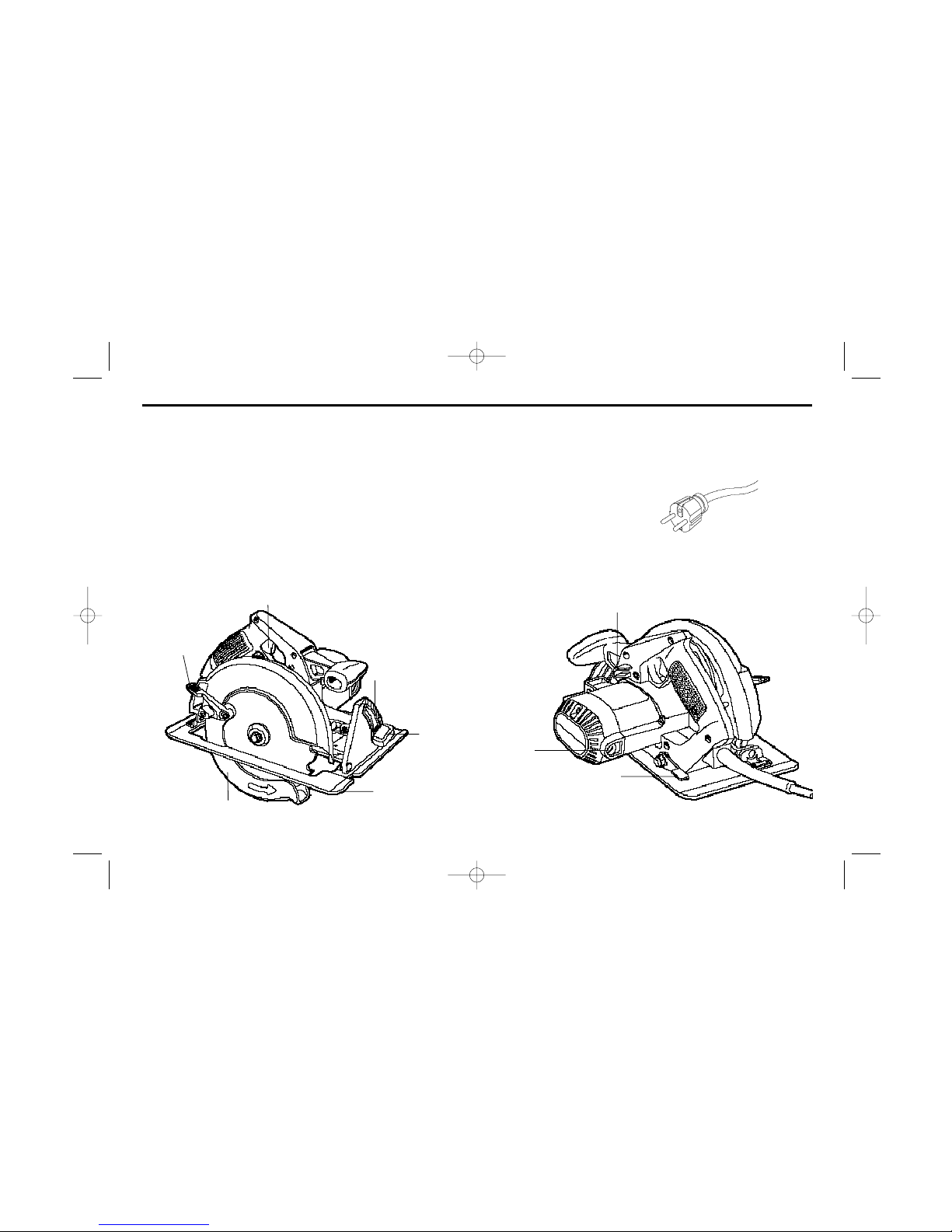
2683-220 7-1/4" Circular Saw
RETRACTING
LEVER
TRIGGER SWITCH
BEVEL
QUADRANT
SHOE
QUADRANT
LEVER OR
KNOB
LOWER GUARD
CORD KEEPER
DEPTH
ADJUSTMENT
LEVER
BRUSH
INSPECTION CAP
220 VOLT PLUG
154577/2683-220 IC 5/17/02 1:47 PM Page 1
Page 4
2
WARNING: When using electric tools, basic safety precautions should
always be followed to reduce risk of fire, electric shock, and personal injury,
including the following:
READ ALL INSTRUCTIONS
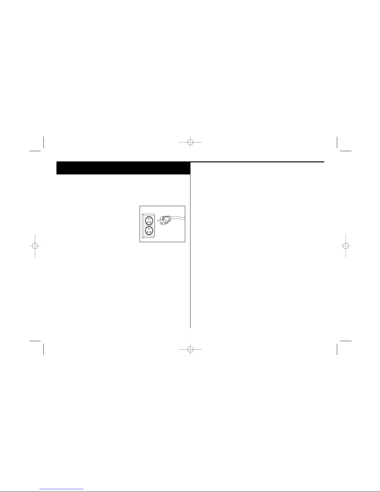
Grounding Instructions
This tool should be grounded while in use to
protect the operator from electric shock. The
tool is equipped with a 3-conductor cord to fit
the proper grounding type receptacle. The green
(or green and yellow) conductor in the cord is
the grounding wire. Never connect the green (or
green and yellow) wire to a live terminal.
The two grounding contacts and the grounding receptacle in the plug must be
connected to a permanent ground, such as a properly grounded outlet. No
adapter is available for a plug as shown in Figure A.
Safety Instructions For All Tools
• KEEP WORK AREA CLEAN. Cluttered areas and benches invite injuries.
• CONSIDER WORK AREA ENVIRONMENT. Don’t expose power tools to rain.
Don’t use power tools in damp or wet locations. Keep work area well lit. Do
not use tool in presence of flammable liquids or gases.
• GUARD AGAINST ELECTRIC SHOCK. Prevent body contact with grounded
surfaces. For example; pipes, radiators, ranges, and refrigerator enclosures.
• KEEP CHILDREN AWAY. Do not let visitors contact tool or extension cord. All
visitors should be kept away from work area.
• STORE IDLE TOOLS. When not in use, tools should be stored in dry, and high
or locked-up place — out of reach of children.
• DON’T FORCE TOOL. It will do the job better and safer at the rate for which it
was intended.
• USE RIGHT TOOL. Don’t force small tool or attachment to do the job of a
heavy-duty tool. Don’t use tool for purpose not intended.
• DRESS PROPERLY. Do not wear loose clothing or jewelry. They can be
caught in moving parts. Rubber gloves and non-skid footwear are
recommended when working outdoors. Wear protective hair covering to
contain long hair.
• USE SAFETY GLASSES. Also use face or dust mask if operation is dusty.
• DON’T ABUSE CORD. Never carry tool by cord or yank it to disconnect from
receptacle. Keep cord from heat, oil, and sharp edges.
• SECURE WORK. Use clamps or a vise to hold work. It’s safer than using your
hand and it frees both hands to operate tool.
• DON’T OVERREACH. Keep proper footing and balance at all times.
• MAINTAIN TOOLS WITH CARE. Keep tools sharp and clean for better and
safer performance. Follow instructions for lubricating and changing
accessories. Inspect tool cords periodically and if damaged, have repaired by
authorized service facility. Inspect extension cords periodically and replace if
damaged. Keep handles dry, clean, and free from oil and grease.
• DISCONNECT OR LOCK OFF TOOLS when not in use, before servicing, and
when changing accessories, such as blades, bits, cutters.
• REMOVE ADJUSTING KEYS AND WRENCHES. Form habit of checking to see
FOR YOUR SAFETY - ALL TOOLS
A
154577/2683-220 IC 5/17/02 1:47 PM Page 2
Page 5
3
1. DISCONNECT PLUG FROM POWER SUPPLY before changing blades, making
cutting depth or bevel adjustments, inspecting, cleaning or when saw is not
being used.
2. KEEP GUARDS IN PLACE AND IN WORKING ORDER. Never wedge or tie
lower guard open. Check operation of lower guard before each use. Do not use
if lower guard does not close briskly and completely over saw blade.
CAUTION: If saw is dropped, lower guard may be bent, restricting full return.
Do not use saw until the lower guard is returned to the proper working order.
3. KEEP BLADES CLEAN AND SHARP. Sharp blades minimize stalling, overload,
kickback, and give a cleaner cut.
4. DANGER: Keep hands away from cutting area. Keep hands away from blades.
Do not reach underneath work while blade is rotating. Do not attempt to
remove cut material when blade is moving.
CAUTION: Blades continue to coast after trigger is released. Never place your
hand on the work surface in front of or behind the saw.
5. SUPPORT LARGE PANELS. Large panels must be supported as shown in
Figure 15 to minimize the risk of overload and kickback from blade pinching.
When cutting operation requires the resting of the saw on the work piece, the
saw should be rested on the larger portion and the smaller piece cut off.
6. USE RIP FENCE. Always use a fence or straight edge guide when ripping.
7. GUARD AGAINST KICKBACK. Kickback occurs when the saw begins to stall
rapidly and is driven back towards the operator. Release the switch
immediately if blade binds or saw stalls. Keep blades sharp. Don’t force tool.
Stay alert. Exercise control. Don’t remove saw from work during a cut while
the blade is moving. A more detailed explanation of kickback follows in the
operation section of this manual.
8. LOWER GUARD. When necessary for accurate starts or when pocket cutting,
raise lower guard with the retracting lever.
9. ADJUSTMENTS. Before cutting be sure depth and bevel adjustments are tight.
10. USE ONLY CORRECT BLADES. Use only blades with 5/8” arbor. Do not use
that keys and adjusting wrenches are removed from tool before turning it on.
• AVOID UNINTENTIONAL STARTING. Don’t carry tool with finger on switch.
Be sure switch is off when plugging in.
• EXTENSION CORDS. Make sure your extension cord is in good condition.
When using an extension cord, be sure to use one heavy enough to carry the
current your product will draw. An undersized cord will cause a drop in line
voltage resulting in loss of power and overheating. The following table shows
the correct size to use depending on cord length and nameplate ampere
rating. If in doubt, use the next heavier gage. The smaller the gage number,
the heavier the cord.
Minimum Gage for Cord Sets
Volts Total Length of Cord in Feet
120V 0-25 26-50 51-100 101-150
240V 0-50 51-100 101-200 201-300
Ampere Rating
More Not more AWG
Than Than
0-6 18161614
6 - 10 18 16 14 12
10-1216161412
12 - 16 14 12 Not Recommended
• OUTDOOR USE EXTENSION CORDS. When tool is used outdoors, use only
extension cords intended for use outdoors and so marked.
• STAY ALERT. Watch what you are doing. Use common sense. Do not operate
tool when you are tired.
• CHECK DAMAGED PARTS. Before further use of the tool, a guard or other
part that is damaged should be carefully checked to determine that it will
operate properly and perform its intended function. Check for alignment of
moving parts, binding of moving parts, breakage of parts, mounting, and any
other conditions that may affect its operation. A guard or other part that is
damaged should be properly repaired or replaced by an authorized service
center unless otherwise indicated elsewhere in this instruction manual. Have
defective switches replaced by authorized service center. Do not use tool if
switch does not turn it on and off.
SAVE THESE INSTRUCTIONS
SAFETY INSTRUCTIONS - CIRCULAR SAWS
154577/2683-220 IC 5/17/02 1:47 PM Page 3
Page 6

4
blades with incorrect size holes. Never use defective or incorrect blade
washers or bolts.
11. AVOID CUTTING NAILS. Inspect for and remove all nails from lumber before
cutting.
12. CAUTION: When sawing into walls, floors, or wherever “live” electrical wires
may be encountered, DO NOT TOUCH ANY METAL PARTS OF THE TOOL!
Hold the saw only by its plastic handles to prevent electric shock if you
accidentally saw into a “live” wire.
13. CAUTION: Some wood contains preservatives such as copper chromium
arsenate (CCA) which can be toxic. When cutting these materials extra care
should be taken to avoid inhalation and minimize skin contact.
SAVE THESE INSTRUCTIONS FOR FUTURE USE
Motor
Your tool is powered by a B&D-built motor. Be sure your power supply agrees
with nameplate marking. 220/240 volts AC means your saw will operate on
alternating current. Lower voltage will cause loss of power and can result in
overheating. All B&D tools are factory tested; if this tool does not operate,
check the power supply.
ADJUSTMENTS AND SET UP
Attaching and Removing Blades
To attach the blade:
1. TURN OFF TOOL AND DISCONNECT FROM POWER SUPPLY.
2. Retract lower blade guard and place inner clamp washer and blade on saw
spindle with printed side of blade out (teeth at bottom of blade pointing
forward - Figure 1). Place outer clamp washer on saw spindle. The larger
surfaces of both washers must face the blade.
3. Thread on blade clamping screw firmly by hand to hold washer in position.
4. Lightly depress the blade lock (Figure 2) while turning the spindle until the
blade stops rotating.
5. Tighten blade clamping screw (clockwise) firmly with the blade wrench
(Figure 3).
NEVER ENGAGE BLADE LOCK WHILE SAW IS RUNNING, OR ENGAGE IN AN
EFFORT TO STOP THE TOOL. NEVER TURN SWITCH ON WHEN BLADE LOCK
IS ENGAGED. SERIOUS DAMAGE TO YOUR SAW WILL RESULT.
When removing the blade:
1. TURN OFF TOOL AND DISCONNECT FROM POWER SUPPLY.
2. Engage the blade lock and unscrew the blade clamping screw by turning it
counterclockwise with the blade wrench.
Cutting Depth Adjustment
1. TURN OFF TOOL AND DISCONNECT FROM POWER SUPPLY.
2. Hold the saw firmly as shown in Figure 4.
3. Loosen (counterclockwise) the depth adjustment lever and move shoe to
obtain the desired depth of cut, as shown in Figure 5.
4. Make sure depth adjustment lever has been retightened (clockwise) before
operating saw.
For the most efficient cutting action, set the depth adjustment so that one
tooth of the blade will project below the material to be cut. This distance is
from the tip of the tooth to the bottom of the gullet in front of it. This keeps
blade friction at a minimum, removes sawdust from the cut, results in cooler,
faster sawing and reduces the chance of kickback. A method for checking for
154577/2683-220 IC 5/17/02 1:47 PM Page 4
Page 7

5
the blade and the left edge of the shoe (standard 6x lumber). The right
dimension is 1-1/2" (standard 2x lumber).
Shoe Alignment
Your saw has been set at the factory for accurate vertical cuts (a 90˚ angle
between the bottom of the shoe and the blade). The edge of the shoe has also
been set parallel to the blade so that it will not bind when using an edge guide.
If the saw should ever need adjusting, it may be done as follows:
ADJUSTING FOR 90˚ CUTS
1. TURN OFF TOOL AND DISCONNECT FROM POWER SUPPLY.
2. Adjust the saw to 0˚ bevel.
3. Place the saw on blade side (Figure 9). Retract blade guard.
4. Loosen quadrant lever or knob (Figure 9). Place a square against the blade
and shoe to adjust the 90˚ setting.
5. Loosen the hex nut with a wrench or needle nose pliers, and move the
adjustment screw so that the shoe will stop at the proper angle as shown in
Figure 10. Lock the screw in place by tightening the hex nut.
6. It may be necessary to adjust the quadrant angle pointer to line up on “0”
after shoe has been adjusted.
correct cutting depth is shown in Figure 6. Lay a piece of the material you plan
to cut along the side of the blade, as shown, and observe how much tooth
projects beyond the material.
NOTE: When using carbide-tipped blades, make an exception to the above
rule and allow only one-half of a tooth to project above the material to be cut.
Bevel Angle Adjustment
The full range of the bevel adjustment is from 0˚ to 50˚. The quadrant is
graduated in increments of 5˚. On the front of the saw is a bevel angle
adjustment mechanism (Figure 7) consisting of a calibrated quadrant and a
lever. To set the saw for a bevel cut:
1. TURN OFF TOOL AND DISCONNECT FROM POWER SUPPLY.
2. Loosen (counterclockwise) the quadrant lever or knob and tilt shoe to the
desired angle by aligning the pointer with the desired angle mark.
3. Retighten lever firmly (clockwise).
NOTE: The quadrant pointer, located between the quadrant lever or knob and
the quadrant, can be adjusted after loosening its screw. Retighten firmly
after adjustment.
Kerf Indicator
The front of the saw shoe has a kerf indicator (Figure 7) for vertical and bevel
cutting. This indicator enables you to guide the saw along cutting lines
penciled on the material being cut. The indicator lines up with the left (inner)
side of the saw blade, which makes the slot or “kerf” cut by the moving blade
fall to the right of the indicator. Guide along the penciled cutting line so that
the kerf falls into the waste or surplus material (Figure 8). Figure 8 shows the
dimensions of the shoe. Note that the left side is 5-1/2" between the left side of
INNER CLAMP
WASHER
RETRACTING LEVER
BLADE
CLAMPING
SCREW
OUTER CLAMP
WASHER
Figure 1
154577/2683-220 IC 5/17/02 1:47 PM Page 5
Page 8

6
TIP OF TOOTH
GULLET
SURFACE OF
WOOD
KERF INDICATOR
QUADRANT
Figure 6
Figure 7
QUADRANT
LEVER OR
KNOB
7. Confirm the accuracy of the setting by checking the squareness of an
actual cut on a scrap piece of material.
ADJUSTING THE SHOE PARALLEL TO THE BLADE
Your saw is adjusted at the factory so that the blade and shoe are parallel. If
these parts become misaligned, adjust as follows:
1. TURN OFF TOOL AND DISCONNECT FROM POWER SUPPLY.
2. Loosen the 2 screws at the adjusting bracket at the rear of the shoe, as
shown in Figure 11.
3. Adjust the shoe until it is parallel to the blade by measuring from the
edge of the shoe to the blade, front & rear. You can measure from the
outside edge of the blade to the shoe as shown in Figure 11 or from the
the inner edge of the blade to the wider part of the shoe. (Do not measure
from the tips of any saw blade teeth.)
4. When the shoe is parallel, tighten all screws.
Figure 2
Figure 3
Figure 4
Figure 5
BLADE LOCK
BRUSH
INSPECTION
CAP
TIGHTEN
LOOSEN
DEPTH
ADJUSTMENT LEVER
MOVE TO
DESIRED DEPTH
OF CUT
154577/2683-220 IC 5/17/02 1:47 PM Page 6
Page 9

7
ADJUSTING DEPTH ADJUSTMENT AND QUADRANT LEVER OR KNOB
It may be desirable to adjust the depth adjustment and quadrant adjustment
levers. (They will sometimes hit the shoe before fully tightening or loosening
completely.)
To adjust either lever, follow the steps below.
1. TURN OFF TOOL AND DISCONNECT FROM POWER SUPPLY.
2. Using a small screwdriver, pry the lock ring off, as shown in Figure 12.
3. Remove the lever and rotate it in the desired direction about 1/8
revolution. (More or less as necessary.)
4. Reinstall the lever and insert the lock ring with concave side against
lever to hold it in place. (see Figure 13)
TOOL OPERATION
Switch
Pull the trigger switch to turn the motor ON. Releasing the trigger turns the
motor OFF. Releasing the trigger also automatically actuates the electric brake
on units so equipped. This tool has no provision to lock the switch in the ON
position, and should never be locked ON by any other means.
Work Piece Support
Figure 14 shows proper sawing position. Note that hands are kept away from
cutting area, and power cord is positioned clear of the cutting area so that it
will not get caught or hung up on the work. Note that a special cord keeper
has been provided on the tool’s handle. Press the cord firmly into the cord
keeper to keep it out of the way but in sight so you know where it is at all
times.
GUIDE ALONG PENCILED CUTTING LINE
SO KERF FALLS IN WASTE STOCK
DESIRED WIDTH
OF CUT
KERF
Align left side of saw blade
with “45” mark, as shown,
for 45˚ bevel
cutting.
Align right side of saw
blade with “0” mark for
straight cutting.
Figure 8
5-1/2"
(140mm)
1-1/2"
(38mm)
WASTE
Figure 9
QUADRANT LEVER
OR KNOB
DIRECTION OF CUT
CORD
KEEPER
Figure 10
Figure 11
QUADRANT
LEVER OR KNOB
HEX NUT
SCREWS
ADJUSTMENT
SCREW
154577/2683-220 IC 5/17/02 1:47 PM Page 7
Page 10

8
To avoid kickback, DO support board or panel NEAR the cut, (Figure 15).
DON’T support board or panel away from the cut, (Figure 16).
WARNING: It is important to support the work properly and to hold the saw
firmly to prevent loss of control which could cause personal injury. Figure 14
illustrates typical hand support of the saw.
ALWAYS TURN OFF TOOL AND DISCONNECT FROM POWER SUPPLY
BEFORE MAKING ANY ADJUSTMENTS!
Place the work with its good side - the one on which appearance is most
important- down. The saw cuts upward, so any splintering will be on the work
face that is up when you saw it.
Cutting
Support the work so that the cut will be on your right. Place the wider portion
of the saw shoe on that part of the work piece which is solidly supported, not
on the section that will fall off when the cut is made. As examples, Figure 14
illustrates the RIGHT way to cut off the end of a board, and Figure 17 the
WRONG way. Always clamp work. Don’t try to hold short pieces by hand!
Remember to support cantilevered and overhanging material. Use caution
when sawing material from below.
Be sure saw is up to full speed before blade contacts material to be cut.
Starting saw with blade against material to be cut or pushed forward into kerf
can result in kickback.
Push the saw forward at a speed which allows the blade to cut without
laboring. Hardness and toughness can vary even in the same piece of
material, and knotty or damp sections can put a heavy load on the saw. When
this happens, push the saw more slowly, but hard enough to keep it working
without much decrease in speed. Forcing the saw can cause rough cuts,
inaccuracy, kickback, and overheating of the motor.
Should your cut begin to go off the line, don’t try to force it back on. Release
the switch and allow blade to come to a complete stop. Then you can
withdraw the saw, sight anew, and start a new cut slightly inside the wrong
one. In any event, withdraw the saw if you must shift the cut. Forcing a
correction inside the cut can stall the saw and lead to kickback. IF SAW
STALLS, RELEASE THE TRIGGER AND BACK THE SAW UNTIL IT IS LOOSE.
BE SURE BLADE IS STRAIGHT IN THE CUT AND CLEAR OF THE CUTTING
EDGE BEFORE RESTARTING.
As you finish a cut, release the trigger and allow the blade to stop before lifting
the saw from the work. As you lift the saw, the spring-tensioned telescoping
guard will automatically close under the blade. Remember the blade is
exposed until this occurs. Never reach under the work for any reason
whatsoever. When you have to retract the telescoping guard manually (as is
necessary for starting pocket cuts) always use the retracting lever.
Figure 12
Figure 13
LOCK RING
LEVER
LOOSEN
TIGHTEN
LOCK NUT
154577/2683-220 IC 5/17/02 1:47 PM Page 8
Page 11

9
NOTE: When cutting thin strips, be careful to ensure that small cutoff pieces
don’t hang up on inside of lower guard.
Ripping
Ripping is the process of cutting wider boards into narrower strips- cutting
grain lengthwise. Hand guiding is more difficult for this type of sawing and
some type of guide should be used. A rip fence (Figure 18) may be
purchased separately for this purpose.
Pocket Cutting
A pocket cut is one that is made in a floor, wall, or other flat surface. Adjust
saw shoe so blade cuts at desired depth.
TURN OFF TOOL AND DISCONNECT FROM POWER SUPPLY.
Tilt saw forward and rest front of the shoe on material to be cut. Using the
retracting lever, retract blade guard to an upward position. Lower rear of shoe
until blade teeth almost touch cutting line. Now release the blade guard (its
contact with the work will keep it in position to open freely as you start the
cut) Figure 19. Start the motor and gradually lower the saw until its shoe rests
flat on the material to be cut. Advance saw along the cutting line until cut is
completed. Release trigger and allow blade to stop completely before
withdrawing the blade from the material. When starting each new cut, repeat
as above. Never tie the blade guard in a raised position.
Kickback
When the saw blade becomes pinched or twisted in the cut kickback can
occur. The saw is thrust rapidly back toward the operator. When the blade is
pinched or bound tightly by the kerf closing down, the blade stalls and the
motor reaction drives the unit backward. When the blade becomes twisted or
misaligned in the cut, the teeth at the back edge of the blade can dig into the
top surface of the wood causing the blade to climb out of the kerf and jump
back toward the operator. Kickback is more likely to occur when any of the
following conditions exist.
Improper work piece support
Sagging or improper lifting of the cutoff piece causing pinching of the blade.
Cutting through material supported at the outer ends only (Figure 16). As the
Figure 14
Figure 15
Figure 16
RIGHT
WRONG
SUPPORT WORK
NEAR CUT
MATERIAL BENDS ON
BLADE CAUSING
HEAVY LOADS OR
KICKBACK
154577/2683-220 IC 5/17/02 1:47 PM Page 9
Page 12

10
material weakens it sags, closing down the kerf and pinching the blade.
Cutting off a cantilevered or overhanging piece of material from the bottom
up in a vertical direction. The falling cut off piece can pinch the blade.
Cutting off long narrow strips (as in ripping). The cutoff strip can sag or
twist closing the kerf and pinching the blade.
Snagging the lower guard on a surface below the material being cut
momentarily reducing operator control. The saw can lift partially out of the
cut increasing the chance of blade twist.
Improper depth of cut setting on saw
Using the saw with an excessive depth of cut setting increases loading on
the unit and susceptibility to twisting of the blade in the kerf. It also
increases the surface area of the blade available for pinching under
conditions of kerf close down.
Blade twisting (Misalignment in Cut)
Pushing harder to cut through a knot, a nail, or hard grain area can cause
blade to twist.
Trying to turn the saw in the cut (trying to get back on the marked line) can
cause blade twist.
Extended reach or operating saw with poor body control (out of balance) can
result in twisting the blade.
Changing grip or body position while cutting can result in blade twist.
Backing unit up to clear blade can lead to twist if not done carefully.
Insufficient allowance for particularly tough materials
Materials that require extra attention: wet lumber, green lumber (material
freshly cut or not kiln dried), pressure treated lumber (material treated with
preservatives or anti-rot chemicals)
Use of dull or dirty blades
Dull blades cause increased loading of the saw. To compensate, an operator
will usually push harder which further loads the unit and promotes twisting
of the blade in the kerf. Worn blades may also have insufficient body
clearance which increases the chance of binding and increased loading.
Lifting the saw when making bevel cuts
Bevel cuts require special operator attention to proper cutting techniques especially guidance of the saw. Both blade angle to the shoe and greater
blade surface in the material increase the chance for binding and
misalignment (twist) to occur.
Restarting a cut with the blade teeth jammed against the material
Figure 17
Figure 19
RIP FENCE
Figure 18
WRONG
154577/2683-220 IC 5/17/02 1:47 PM Page 10
Page 13

11
The saw should be brought up to full operating speed before starting a cut
or restarting a cut after the unit has been stopped with the blade in the kerf.
Failure to do so can cause stalling and kickback.
Any other conditions which could result in pinching, binding, twisting, or
misalignment of the blade could cause kickback. Refer to the sections on
“Adjustments and Set-Up” and “Operation” for procedures and techniques
that will minimize the occurrence of kickback.
MAINTENANCE
Cleaning
Use only mild soap and a damp cloth to clean the tool. Many household
cleaners contain chemicals which could seriously damage plastic. Also, do
not use gasoline, turpentine, lacquer or paint thinner, dry cleaning fluids or
similar products. Never let any liquid get inside the tool; never immerse any
part of the tool into a liquid.
Lubrication
Self lubricating ball and roller bearings are used in the tool and relubrication is
not required. However, it is recommended that, once a year, you take or send
the tool to a B&D authorized service center for a thorough cleaning,
inspection, and lubrication of the gear case.
Brushes
TURN OFF TOOL AND DISCONNECT FROM POWER SUPPLY BEFORE
SERVICING.
Inspect carbon brushes regularly by unplugging tool, removing the brush
inspection cap (Figure 2) and withdrawing the brush assembly. Keep brushes
clean and sliding freely in their guides. Always replace a used brush in the
same orientation in the holder as it was prior to removal. Carbon brushes have
varying symbols stamped into their sides, and if the brush is worn down to the
line closest to the spring, they must be replaced. Use only identical B&D
brushes. Use of the correct grade of brush is essential for proper operation of
electric brakes on units so equipped. New brush assemblies are available at
B&D service centers. The tool should be allowed to “run in” (run at no load
without a blade) for 10 minutes before use to seat new brushes. This is
especially important for saws equipped with electric brakes which may be
erratic in operation until the brushes are properly seated (worn in). While
“running in” DO NOT TIE, TAPE, OR OTHERWISE LOCK THE TRIGGER
SWITCH ON. HOLD SWITCH BY HAND ONLY.
IMPORTANT!
To assure product SAFETY and RELIABILITY, particularly for double insulated
tools, repairs, maintenance and adjustment (excluding maintenance
described in this manual) should be performed by B&D service centers or
authorized service centers, using identical B&D replacement parts.
Blades
A dull blade will cause slow, inefficient cutting overload on the saw motor,
excessive splintering, and could increase the possibility of kickback. It is a
good practice to keep extra blades on hand so that sharp blades are available
while the dull ones are being sharpened. (See “Saws-Sharpening” in the
yellow pages.) In fact, many lower priced blades can be replaced with new
ones at very little cost over the sharpening price.
Hardened gum on the blade will slow down the cutting. This gum can best be
removed with kerosene, turpentine, or oven cleaner. B&D manufactures a
complete line of saw blades and the following types of blades are available
from your dealer.
154577/2683-220 IC 5/17/02 1:47 PM Page 11
Page 14

12
Combination Blade- For general-purpose ripping and cutting.
Chisel Tooth Combination- Specially designed for general-purpose ripping
and crosscutting.
Framing/Rip Combination- For facing, roofing, siding, sub-flooring,
framing, form cutting.
Cross Cut Blade- For smoother, faster cross cutting.
Ripping Blade- Fast for rip cuts.
Plywood Blade- For smooth cuts in plywood. Reduce splintering.
Planer Blade- For very smooth ripping and cross cutting.
Flooring Blade- For sawing where nails may be occasionally encountered.
Metal Cutting Blade- For cutting aluminum, copper and other soft metals.
Friction Blade-For cutting corrugated, galvanized sheets.
Carbide Tipped Blade- For longest sawing without blade sharpening. Cuts
wood, transite, cemesto board, asbestos, formica, masonite, and similar
materials.
ACCESSORIES
Recommended accessories for use with your tool are available at extra cost
from your distributor or your local service center. A complete listing of
service centers is included with your tool.
CAUTION: The use of any non-recommended accessory may be hazardous.
If you need any assistance in locating any accessory, call 1-800-9-BD TOOL
(1-800-923-8665) or contact Black & Decker, Consumer Services
Department, 626 Hanover Pike, P.O. Box 618, Hampstead, MD 21074.
RIP FENCE: Attaches to top of saw shoe. Permits rip cuts without a penciled
guide line.
SAW PROTRACTOR: Guides saw for accurate cut-off work. Adjusts from
0 to 70 degrees.
154577/2683-220 IC 5/17/02 1:47 PM Page 12
Page 15

13
One Year Free Maintenance
All B&D tools for Industry and Construction are covered under a one year
free maintenance program where B&D will inspect your tool for safety and
provide necessary maintenance or repairs, including normal wear and tear
parts, for one year, FREE OF CHARGE.
Full Warranty
All B&D tools for Industry and Construction are warranted to be free of any
defects in materials or workmanship. Upon thorough examination of tool,
B&D will repair or replace, at our option, any product that is determined to
be defective.
Conditions
The service/safety check and the warranty do not apply to: repairs made or
attempted by anyone other than an authorized B&D service location; misuse,
abuse, neglect, improper application of the tool; missing parts; or normal wear
and tear (after first year of ownership). Please return the complete unit,
transportation prepaid, to any B&D factory owned or B&D authorized service
center location (list provided with tool or see yellow pages under “Tools
Electric”).
Every B&D tool is of the highest quality.
If you wish to contact us regarding this product, please call toll
free between 8:00am and 8:00pm ET, seven days a week:
1-800-9-BD TOOL
(1-800-923-8665)
154577/2683-220 IC 5/17/02 1:47 PM Page 13
 Loading...