

Page 1
IMPORTANT
To assure product SAFETY and RELIABILITY, repairs, maintenance and adjust
ment, (including brush inspection and replacement) should be performed by
Black <Sc Decker Service Centers or other qualified service organizations, always
using Black & Decker replacement parts.
COMMERCIAL/INDUSTRIAL USE WARRANTY
Black & Decker warrants this product for one year from date of purchase. We will
repair without charge, any defects due to faulty material or workmanship. Please
return the complete unit, transportation prepaid, to any Black & Decker Service
Center or Authorized Service Station listed under "Tools Electric” in the yellow
pages. This warranty does not apply to accessories or damage caused where
repairs have been made or attempted by others.
OWNER’S MANUAL
Your Black & Decker Electric SCRUGUN® is a
heavy-duty tool, capable of continuous produc
tion service on assembly operations. For dis
assembly work, there is a reversing switch con
veniently located on the handle back, opposite
the trigger switch. A wide variety of 1/4" hex
drive accessories—bits, sockets, nutsetters, ex
tensions, etc., permit this tool to drive or remove
many types of threaded fasteners.
For personal safety and for proper operation of
the Scrugun®, please take the time to carefully
read all of the safety rules and instructions in
this booklet. Don’t forget to send In the owner
registration card.
Form No. 740228-02
BLACK & DECKER (U.S.) INC.,
626 Hanover Pike, Hampstead, Maryland 21074
(APR83-CD)
Printed in U.S.A.
THANK YOU for buying BLACK & DECKER!
. DOUBLE INSULATED .
HEAVY-DUTY
SCRUGUN*
SCREWDRIVERS
Cat. Nos.
2020-10 POSITIVE CLUTCH
2025-10 VERSA-CLUTCH®
2033- 10 DRYWALL
2034- 10 DRYWALL
2022-10 POSITIVE CLUTCH
2032-10 DRYWALL
2034-15 DRYWALL
Page 2
ACCESSORY ASSEMBLY & ADJUSTMENTS
The 1/4' HEX DRIVE QUICK CHANGE CHUCK (Fig. 3)
is used on all positive and versa-clutch units. A bail retainer pro
vides positive locking of ail accessories in the chuck. Push for
ward on the ball retainer and hold while inserting or removing ac
cessories. Release for positive accessory retention.
BALL GROOVE
1/4" HEX DRIVE
BALL
RETAINER
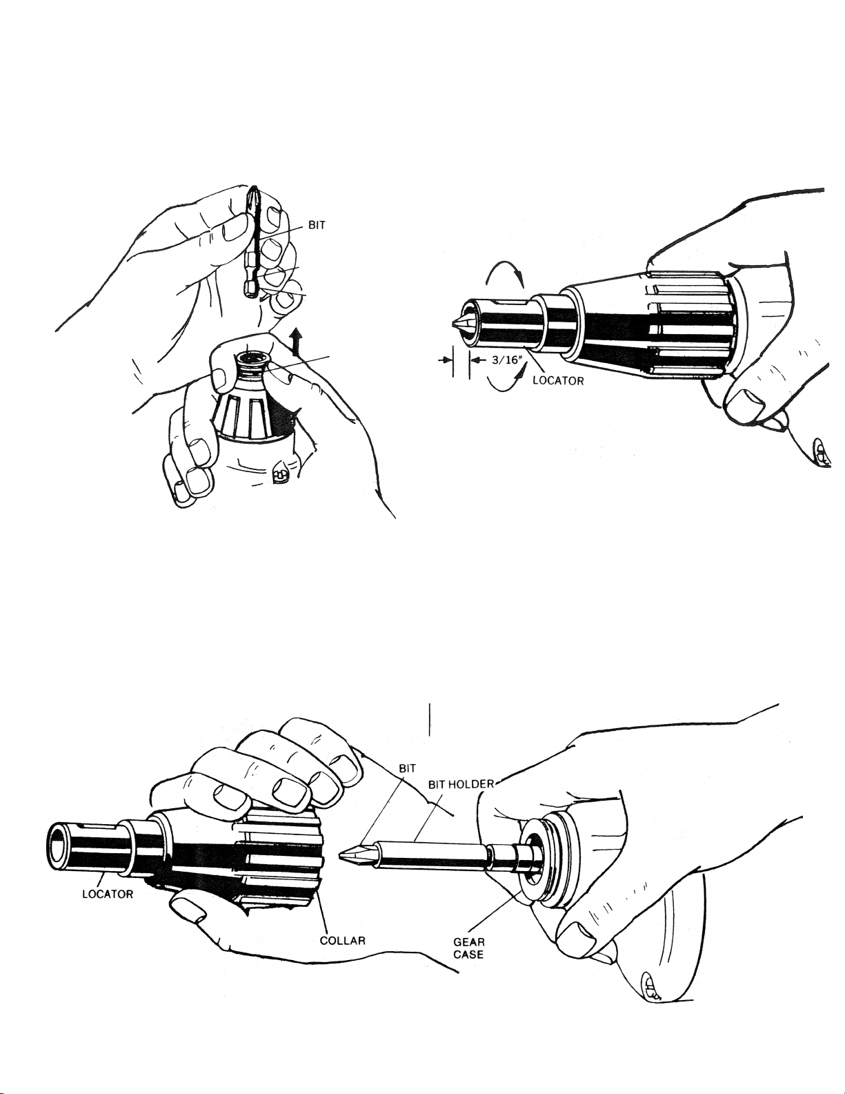
DEPTH ADJUSTMENT ON DRYWALL UNITS (Fig. 5)
1. Turn locator until end of bit extends 3/16" beyond end of
locator.
2. Test drive a fastener in scrap material to determine if
fastener is correctly seating.
3. Further adjustment may be necessary to Increase or
decrease the fastener depth.
Figure 5
Figure 3
ACCESSORY ASSEMBLY & ADJUSTMENT FOR DRYWALL UNITS (Fig. 4)
The 1/4" HEX DRIVE BALL LOCK CHUCK is used on all drywall
screwdrivers.
To change Bit Holders on Drywall Units
1. Unscrew collar AND locator assembly from gear case (left
hahd thread).
NOTE: There is no need to unscrew locator from collar.
2. Pull bit holder straight out with pliers, if it is difficult to
remove.
3. Push new bit holder Into spindle until ball lock snaps in
groove In bit holder shank.
4. Replace collar and locator assembly.
TO INCREASE, turn the locator so that end of bit extends further
from end of locator.
TO DECREASE, turn the locator so that end of bit Is closer to end
of locator.
Black & Decker Drywall Units have very fine depth settings, each
“detent” is .0052" or one revolution of the locator equals .083"
change in depth setting.
Figure 4
Page 3

SCREWDRIVER ACCESSORIES continued
Hex Drive Shank Extensions
*For use with 1/4" square drive sockets—1/4" hex.
Sockets for the above:
FOR DRIVING £jQl
HEX NUTS AND NonSHEET METAL
SCREWS 1/4" Sq. Drive
3,4 3,4
5 5 6
6 6
8 8
10
12,14,1/4
12
10,12
14,16, 1/4
14,1/4
SHANK SIZE
1/4"=^
1/4"^
TYPE
Magnetic 3/8"
Magnetic
SOCKET SIZE
1/4"
5/16"
1/4"
5/16"
3/8" 9/16"
4,5 3
8
10
12
1/4
1/4
SQ. DR.
1/4"
1/4" 6"
DIAM.
1/2"
1/2"
9/16"
7/16"
1/2"
4 5
5
6.8
10
12,1/4
12
LENGTH
2"
LENGTH
7/8"
7/8"
15/16"
7/8"
7/8"
7/8"
4
6
8
10
12,1/4 10
12
3,4
5.6
2
_
8
10
1/4" Hex Bits With Rotating Finder For Use With Any 1/4" Hex Drive
Power Tool
4.5
8
8
10
12
Mise. SCREWDRIVER ACCESSORIES
i* Hex Bit Extifision
For yst with 1/4* Hex Shanks and/or
other extensions.
1/4* oifware Drive Magnetic Socket
For driving 8 Poim^di and
Steel Headed Screws.
Heavy-Duty Tool Box
Cat. No. 50078
BIT
LENGTH
4.5
8 .
8
10
12
4,5.6 4.5 4.5
8,10
8,10 6 8
12
1/4
6
8.10 10 8.10
—
8
12
5.6
5.6
3-1/2"
3-1/2"
6"
3-1/2"
3-1/2"
Magnetic Bit Tip Holders
for Drywall Scruguns
1/r Hex Shank for 1/4» Hex Tip (3-3/32
tong) for use with all Drywall
SCRUGUNS® EXTRA LENGTH BIT TIP
DRIVE BODY.
1/4' Hex Shank for 1/4' Hex Tip (2-31/32
long) for use with all Drywall
SCRUGUNS® STANDARD LENGTH
STAINLESS STEEL BODY. (Standard
equipment on H.D. drywall SCRUGUNS®)
ggz
Scrugun® Holster Cat. No. 69590
attaches to belts up to 2-3/4" wide.
BELT CLIP Cat. No. 69600
For all H.D. SCRUGUN Screwdrivers.
(Standard equipment on H.D. drywall
SCRUGUNS®)
Page 4

VERSA-CLUTCH FOR DRIVING A
WIDE RANGE OF FASTENERS
RPM
SCREWS SCREWS SCREWS SCREWS SCREWS SCREWS
0-1200
1. Install proper fastener driving accessory and set screwdriver for
correct rotation.
2. Adjust clutch setting. See Fig. 4.
3. Place fastener in accessory, contact workpiece and apply
pressure to seat fastener keeping clutches engaged.
4. Upon fastener seating the clutches will ratchet. Disengage
screwdriver from fastener.
NOTE: With Versa-Clutch the operator has the ability to "override”
clutch ratchet if a fastener hits a wood knot, variable hardness in
steel workpieces or incorrect pilot holes. Increased operator
pressure will usually cause the clutches to "pick-up” and continue to
seat the fastener. Further, a quick twist of the collar will change the
clutch setting to overcome most driving difficulties and will provide
for immediate change in torque output giving the operator option to
drive a range of fastener sizes.
MAINTENANCE
NOMINAL CAPACITY
WOOD LAG DRILL CUTTING METAL MACHINE
#12
1/4" w/pilot hole
SELF THREAD SHEET
1/4" 1/4"
3/16" CRS
1/4"
1 /4"
CLEANING
With the motor running, blow dirt and dust out of all air vents with
dry air at least once a week. Wear safety glasses when performing
this.
Exterior plastic parts may be cleaned with a damp cloth and mild
detergent. Although these parts are highly solvent resistant, NEVER
use solvents.
CLUTCH FACE
CHANGING CLUTCHES (Fig. ?) FOR VERSA-CLUTCH ONLY
1. Remove clutch housing by unscrewing in direction of arrow
(left hand thread).
2. Clamp tool or clutch housing in a resilent clamp.
3. Remove round clutch retaining rings ■ with a very small
screwdriver or sharp pointed tool.
4. Install new clutches and new retaining rings.
NOTE: If the output spindle slides toward Inside of gear case,
remove dead spindle spring and thread a 5/16" -18 bolt or
cap.screw into end of spindle and lift up to expose retaining
ring groove. Re-assemble dead spindle spring allowing no
more than 1/4" projecting from end of spindle.
5. Relubricate clutches. (See lubrication'
CHANGING CLUTCHES (Fig. 8) FOR POSITIVE CLUTCH & DRYWALL UNITS ONLY
CLUTCH
OUTPUT
SPINDLE
RETAINING
RING
1. Remove three gear case screws from front and disassemble
^ gear case.
2. Clamp output spindle In a resilient clamp.
3. Remove round clutch retaining rlng^ with a very small
screwdriver or sharp pointed tool.
4. Install a new clutch and retaining ring.
5. Relubricate clutches and gearing. (See lubrication).
5/16"-18 SCREW
Figure 7
Figure 8
 Loading...