

Page 1
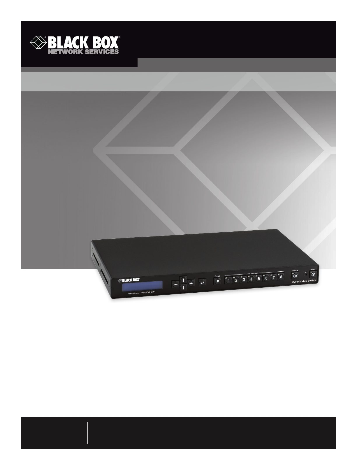
DVI-D Matrix Switches
Routes DVI video signals (and their implicit display
information) from inputs to outputs.
Conforms to DVI 1.0 standard.
Provides a maximum data transfer rate of 1.65 Gbps on every video
differential line.
Supports resolutions up to 1920 x 1200 at 60 Hz on each of the inputs
and outputs.
January 2010
XP T-DVI4X4 XP T-DVI8X8
XP T-DVI4X8 XP T-DVI +4
XPT-DVI8X4 XPT-DVIEAR
Customer
Support
Information
Order toll-free in the U.S.: Call 877-877-BBOX (outside U.S. call 724-746-5500) •
FREE technical support 24 hours a day, 7 days a week: Call 724-746-5500 or fax 724-746-0746 •
Mailing address: Black Box Corporation, 1000 Park Drive, Lawrence, PA 15055-1018 •
Web site: www.blackbox.com • E-mail: info@blackbox.com
Page 2

DVI-D Matrix Switches
Trademarks Used in this Manual
Black Box and the Double Diamond logo are registered trademarks of BB Technologies, Inc.
Windows, Microsoft, and Internet Explorer are registered trademarks of Microsoft Corporation.
Opera is a registered trademark of Opera Software ASA Corporation.
Firefox is a registered trademark of the Mozilla Foundation.
Any other trademarks mentioned in this manual are acknowledged to be the property of the trademark owners.
Page 2
We‘re here to help! If you have any questions about your application
or our products, contact Black Box Tech Support at 724-746 -5500
or go to blackbox.com and click on “Talk to Black Box.”
You’ll be live with one of our technical experts in less than 20 seconds.
724-746-5500 | blackbox.com
Page 3

FCC and IC RFI Statements/Safety Requirements
Federal Communications Commission and Industry Canada Radio Frequency Interference
Statements
This equipment generates, uses, and can radiate radio-frequency energy, and if not installed and usedproperly, that is, in strict
accordance with the manufacturer’s instructions, may cause inter ference to radio communication. It has been tested and found
to comply with the limits for a Class A computing device in accordance with the specifications in Subpart J of Part 15 of FCC rules,
which are designed to provide reasonable protection against such interference when the equipment is operated in a commercial
environment. Operation of this equipment in a residential area is likely to cause interference, in which case the user at his own
expense will be required to take whatever measures may be necessary to correct the interference.
Changes or modifications not expressly approved by the party responsible for compliance could void the user’s authority to
operate the equipment.
This digital apparatus does not exceed the Class A limits for radio noise emis sion from digital apparatus set out in the Radio
Interference Regulation of Industry Canada.
Le présent appareil numérique n’émet pas de bruits radioélectriques dépassant les limites applicables aux appareils numériques
de la classe A prescrites dans le Règlement sur le brouillage radioélectrique publié par Industrie Canada.
Safety Requirements
The DVI-D Matrix Switch may only be operated on systems having power earth (PE) for grounding the system chassis. Never cover or destroy
the power earth contact of the power cord when plugged to the unit or the power outlet.
Page 3
Page 4

DVI-D Matrix Switches
Instrucciones de Seguridad
(Normas Oficiales Mexicanas Electrical Safety Statement)
1. Todas las instrucciones de seguridad y operación deberán ser leídas antes de que el aparato eléctrico sea operado.
2. Las instrucciones de seguridad y operación deberán ser guardadas para referencia futura.
3. Todas las advertencias en el aparato eléctrico y en sus instrucciones de operación deben ser respetadas.
4. Todas las instrucciones de operación y uso deben ser seguidas.
5. El aparato eléctrico no deberá ser usado cerca del agua—por ejemplo, cerca de la tina de baño, lavabo, sótano mojado o cerca
de una alberca, etc..
6. El aparato eléctrico debe ser usado únicamente con carritos o pedestales que sean recomendados por el fabricante.
7. El aparato eléctrico debe ser montado a la pared o al techo sólo como sea recomendado por el fabricante.
8. Servicio—El usuario no debe intentar dar servicio al equipo eléctrico más allá a lo descrito en las instrucciones de operación.
Todo otro servicio deberá ser referido a personal de servicio calificado.
9. El aparato eléctrico debe ser situado de tal manera que su posición no interfiera su uso. La colocación del aparato eléctrico
sobre una cama, sofá, alfombra o superficie similar puede bloquea la ventilación, no se debe colocar en libreros o gabinetes
que impidan el flujo de aire por los orificios de ventilación.
10. El equipo eléctrico deber ser situado fuera del alcance de fuentes de calor como radiadores, registros de calor, estufas u otros
aparatos (incluyendo amplificadores) que producen calor.
11. El aparato eléctrico deberá ser connectado a una fuente de poder sólo del tipo descrito en el instructivo de operación, o como
se indique en el aparato.
12. Precaución debe ser tomada de tal manera que la tierra fisica y la polarización del equipo no sea eliminada.
13. Los cables de la fuente de poder deben ser guiados de tal manera que no sean pisados ni pellizcados por objetos colocados
sobre o contra ellos, poniendo particular atención a los contactos y receptáculos donde salen del aparato.
14. El equipo eléctrico debe ser limpiado únicamente de acuerdo a las recomendaciones del fabricante.
15. En caso de existir, una antena externa deberá ser localizada lejos de las lineas de energia.
16. El cable de corriente deberá ser desconectado del cuando el equipo no sea usado por un largo periodo de tiempo.
17. Cuidado debe ser tomado de tal manera que objectos liquidos no sean derramados sobre la cubierta u orificios de ventilación.
18. Servicio por personal calificado deberá ser provisto cuando:
A: El cable de poder o el contacto ha sido dañado; u
B: Objectos han caído o líquido ha sido derramado dentro del aparato; o
C: El aparato ha sido expuesto a la lluvia; o
D: El aparato parece no operar normalmente o muestra un cambio en su desempeño; o
E: El aparato ha sido tirado o su cubierta ha sido dañada.
Page 4
724-746-5500 | blackbox.com
Page 5

Table of Contents
Chapter Page
1. Specifications........................................................................................................................................................................6
2. Overview ...........................................................................................................................................................................7
2.1 Introduction ...................................................................................................................................................................7
2.2 What’s Included ............................................................................................................................................................7
2.3 Hardware Description ....................................................................................................................................................8
2.3.1 Front Panel .......................................................................................................................................................... 8
2.3.2 Back Panel ..........................................................................................................................................................9
3. Setup and Cabling .............................................................................................................................................................. 10
3.1 Operation Location Requirements ............................................................................................................................... 10
3.2 Setup and Mounting ................................................................................................................................................... 10
3.3 Electrical Connections..................................................................................................................................................10
3.3.1 Connecting the Power ......................................................................................................................................10
3.3.2 Attaching DVI Video Sources ............................................................................................................................10
3.3.3 Attaching DVI Display Devices........................................................................................................................... 11
3.3.4 RS-232 Connection ........................................................................................................................................... 11
3.3.5 TCP/IP Connection ............................................................................................................................................ 11
3.3.6 Checking Your Cabling ..................................................................................................................................... 12
4. Operation ......................................................................................................................................................................... 13
4.1 Powering On/Off; Standby Operation ......................................................................................................................... 13
4.2 Operation Outline ........................................................................................................................................................ 13
4.3 Setting Up Video Connections between Inputs and Outputs ...................................................................................... 13
4.3.1 Making a Connection ....................................................................................................................................... 13
4.3.2 Modifying or Breaking an Existing Connection ................................................................................................. 14
4.4 Saving and Recalling Presets ........................................................................................................................................14
4.4.1 Saving a Preset .................................................................................................................................................. 14
4.4.2 Recalling a Preset Setup ....................................................................................................................................14
4.5 Menu Functions ........................................................................................................................................................... 15
4.5.1 Menu System .................................................................................................................................................... 15
4.5.2 Menu Tree ........................................................................................................................................................16
4.6 Console and Telnet Access ..........................................................................................................................................17
4.6.1 Introduction to Console/Telnet ......................................................................................................................... 17
4.6.2 Console Command Descriptions .......................................................................................................................18
4.7 Web Server .................................................................................................................................................................. 26
5. About DVI Routing and EDID Handling ..............................................................................................................................27
5.1 DVI Routing ................................................................................................................................................................. 27
5.2 EDID Handling .............................................................................................................................................................27
5.2.1 EDID Emulation (“STATIC”) ............................................................................................................................... 27
5.2.2 EDID Follow (“FOLLOW”) .................................................................................................................................27
5.2.3 EDID Pass-Through (“THROUGH”) .................................................................................................................... 28
6. Troubleshooting .................................................................................................................................................................29
6.1 Calling Black Box ......................................................................................................................................................... 29
6.2 Shipping and Packaging ..............................................................................................................................................29
Page 5
Page 6

DVI-D Matrix Switches
1. Specifications
Air Pressure: Operating and Storage: 700 hPa to 1060 hPa
Color: Black (powdered) with white printing
Mounting Orientation: Desktop: horizontal on rubber stands;
Rackmount: (2) 19" (1U) brackets (included)
Protocol: RS-232 compatible, 57.6 kbps, 8 data bits, no parity, 1 stop bit, RXD/TXD 2-wire mode with X-ON/X-OFF handshake
Resolution: DVI inputs: 640 x 480 to 1920 x 1200 and HDTV 720p, 1080i, 1080p;
DVI outputs: 640 x 480 to 1920 x 120 and HDTV 720p, 1080i, 1080p
Standards: DVI 1.0 compliant; DIN EN 55022 emissions; DIN EN 61000-4-2, DIN EN61000-4-4, and DIN EN 61000-4-5 noise
immunity; Class I protection classification; IP40 protection against dust and humidity, DDC EDID 1.3
Supported Input Signals: Video formats: All DVI 1.0 compliant;
Pixel rate: 18–165 megapixels per second;
Supported video resolutions: DOS (640 x 480 @ 60 Hz) up to WUXGA (1920 x 1200 @ 60 Hz)
Connectors: Power: (1) IEC-320, rear side;
TCP/IP: RJ-45 F 8-pin 10/100M;
RS-232: DB9 F;
DVI-D (inputs and outputs): (16) DVI-D
Indicators/User Controls: (1) blue integrated LED;
(16) push buttons for front panel control
Temperature Tolerance: Operating: 50 to 104° F (10 to 40° C);
Storage: 32 to 149° F (0 to 65° C)
Humidity Tolerance: Operating: 30 to 75%;
Storage: 20 to 80%
Power: 100–240 VAC, 47–63 Hz, 2 A
Size: 1.7"H x 17.2"W x 10.2"D (4.4 x 43.6 x 26 cm)
Weight: 5.3 lb. (2.4 kg)
Table 1-1. RS-232 DB9 F connector pinning.
Pin Description
2 Transmit data (TXD)
3 Receive data (RXD)
5 System ground
Table 1-2. TCP/IP RJ-45 connector pinning.
Pin Description
1 TX+
2 TX 3 RX+
4 Connected to Pin 5
5 Connected to Pin 4
6 RX 7 Connected to Pin 8
8 Connected to Pin 7
Page 6
724-746-5500 | blackbox.com
Page 7

Chapter 2: Overview
2. Overview
2.1 Introduction
The DVI-D Matrix Switch is a pure digital crosspoint switch for digital DVI video signals. It simultaneously connects up to eight DVI
sources to up to eight display devices. For each video source, you can either use a “point-to-point” mode (where you connect
exactly one source to exactly one display device), or a “point-to-multipoint” configuration, where the video signal of one input is
distributed to several display devices.
Four models are available:
• 4 x 4 DVI-D Matrix Switch (XPT-DVI4X4)
• 4 x 8 DVI-D Matrix Switch (XPT-DVI4X8)
• 8 x 4 DVI-D Matrix Switch (XPT-DVI8X4)
• 8 x 8 DVI-D Matrix Switch (XPT-DVI8X8)
You can operate the Matrix Switch in four ways:
1. manually using the front-panel switches (buttons)
2. remotely using RS-232 control
3. remotely using the built-in Web server (and your preferred Internet browser)
4. remotely using a Telnet console
The Matrix Switch has a blue LED display on the front faceplate. It normally shows the actual switching state (the current connections between the inputs and outputs). When operated remotely using the Web interface, the current switching state of the
matrix displays graphically. With console control (RS-232 or Telnet), you can query the switching state using a command language.
When changing DVI connections between video sources and display devices, not only must you switch the video connections/
information, but you must also properly handle the EDID information (which is mandatory in the DVI standards). The Matrix
Switch manages this automatically, according to your setup configuration.
2.2 What‘s Included
• (1) DVI-D Matrix Switch
• (1) 6.4-ft. (2-m) IEC-320 power cord
• (1) DB9 F-to-DB9 M RS-232 serial cable, straight-pinned
• (2) 19-inch mounting brackets, one with additional center cutout to support ventilation. (This bag will also have eight black
M4x5 mm screws.)
• (4) black rubber stickers (used as unit stands in desktop configuration)
• This user’s manual on CD-ROM
Page 7
Page 8

DVI-D Matrix Switches
2.3 Hardware Description
All four Matrix Switches have the same components, but they are used differently. Figures 2-1 and 2-2 show the front and back
panels of the switches. Tables 2-1 and 2-2 describe their functions.
2.3.1 Front Panel
Figure 2-1 shows the front panel of the DVI-D Matrix Switch. Table 2-1 describes its components’ functions.
3
1
Table 2-1. DVI-D Matrix Switch front panel components.
Number Component Description
1 (1) blue integrated LED display Shows the current connections between the inputs and outputs (see Figure
2 (4) arrow keys Use the Up, Down, Left, and Right arrow keys to navigate through menu
3 (1) Enter key Press this key to open a menu on the integrated LED display or to accept a
4 (1) Preset button Press this key save or break a preset, or to recall a saved preset
5 (8) Channel buttons Press for quick make or break of routing connections and easy selection of
6 (1) Confirm (OK) button Reserved for future use
2
Figure 2-1. DVI-D Matrix Switch, front panel.
4-1 for an example)
functions
menu selection
preset or recall
4
5
7
6
8
7 (1) IR cutout Reserved for future use
8 (1) Power button Press to power on/off the switch.
Page 8
724-746-5500 | blackbox.com
Page 9
Chapter 2: Overview
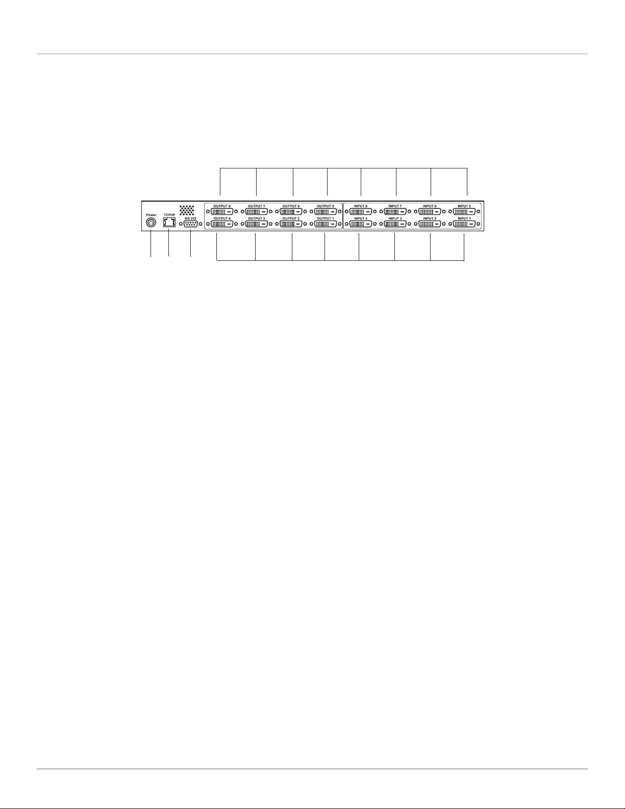
2.3.2 Back Panel
Figure 2-2 shows the back panel of the DVI-D Matrix Switch. Table 2-2 describes its components’ functions.
12
9
10
11
Figure 2-2. DVI-D Matrix Switch, back panel.
12
Table 2-2. DVI-D Matrix Switch back panel components.
Number Component Description
9 (1) DIN connector Power connector
10 (1) RJ-45 F 8-pin connector 10/100M TCP/IP access
11 (1) RS-232 DB9 connector Serial console port
12 (16) DVI-D connectors Connect to Input and output devices
Page 9
Page 10

DVI-D Matrix Switches
3. Setup and Cabling
3.1 Operation Location Requirements
The Matrix Switch has 40° Ingress Protection (IP) against dust and humidity.
Choose a mounting or operation location where no danger of fluids entering exists. Make sure that the environment falls within
the specified temperature and humidity ranges (see Chapter 1: Specifications for details).
3.2 Setup and Mounting
You can operate the Matrix Switch on a shelf or tabletop. Attach the four rubber feet (included) to each corner on the bottom of
the unit.
Or, you can mount the Matrix Switch in a 19-inch rack, using the brackets supplied. Bracket-mounting is simple. The only tool you
need is a screwdriver (Phillips size 2). Follow these steps:
1. Start on the left-hand side of the unit (the front is the side with the buttons) and unscrew the two front and the two middle
screws completely. Take the bracket that has a center cutout and attach it to the left-hand side of switch, using the longer
M4x5 mm screws contained in the bracket’s bag. Make sure that the switch chassis’ ventilation cutout is not blocked significantly by the newly attached bracket.
2. Repeat Step 1 on the right-hand side, using the remaining bracket.
NOTE: When installing the switch on a desktop or in a rack, make sure that nothing will cover the ventilation cutouts on the left-
hand side of the unit.
3.3 Electrical Connections
3.3.1 Connecting the Power
1. Attach the power supply cord to the switch’s IEC-320 connector, which is located on the back of the unit. Now plug the power
plug into a wall outlet.
2. The Matrix Switch has no main power switch, so it will immediately start operation after attaching the unit to a powered wall
outlet.
3. After 10 to 15 seconds, the switch will boot and be ready for operation.
4. The power button’s blue LED should be permanently on when the switch is powered on and active. If the main power fails and
then returns, the switch will return to the active state.
5. To turn off the Matrix Switch, unplug the power cable from the outlet.
CAUTION: Never expose any cables to mechanical stress such as bending or pulling. This can damage cables and impact security.
3.3.2 Attaching DVI Video Sources
The next step in setup procedure is attaching video sources.
1. To avoid damaging your Matrix Switch and your existing video sources, power off ALL units before connecting any components. Power off all video sources, too.
2. Connect your DVI video sources to the Matrix Switch, using your DVI-D-video cables (part number EVNDVI02, not included),
one after another. All Matrix Switch inputs of XPT-DVInxn will be labeled with “Input 1” to “Input 8.” You can use any input
you want for a specific source: all inputs are electrically identical.
3. Make a note of all input connections, so that you know which source goes to which input number.
4. You can use any DVI-D cable. However, with high-quality cable you can place your video source up to 112 feet (35 m) away
from the Matrix Switch. Each input has a signal equalizer that refreshes the signal to standard levels.
Page 10
724-746-5500 | blackbox.com
Page 11

Chapter 3: Setup and Cabling
NOTE: If you have the XPT-DVI4X4 or XPT-DVI4X8, the inputs labeled “Input 5” to “Input 8” are not used. You can’t route signals
from these inputs to any output. Your equipment will not be damaged if you attach video sources to these inputs by
accident.
5. Install and tighten the screws on the male DVI connector.
3.3.3 Attaching DVI Display Devices
1. Connect your display devices (for example, monitors, LCDs, or beamers) to the outputs of the Matrix Switch, using your DVI-D
cables (not included, part number EVNDVI02). All outputs of the unit are labeled “Output 1” to “Output 8.” Use any of the
available outputs for your devices: all outputs are electrically identical.
NOTE: If you have the XPT-DVI4X4 or XPT-DVI8X4, the outputs labeled “Output 5” to “Output 8” are not used. You can’t route
signals from these inputs to any output. Your equipment will not be damaged if you attach video sources to these outputs
by accident.
2. Write down which output goes to which of your display devices, so you have a record of the configuration.
NOTE: Do not use DVI cables longer than 16 feet (5 m) as output cables when using maximum video resolutions such as 1600 x
1200 pixels.
3. Install and tighten the screws on the male DVI connector.
3.3.4 RS-232 Connection
If you intend to control the XPT-DVInxn matrix switch by a PC or laptop using the RS-232 serial interface, connect the included
serial cable to the DB9 F connector on the back of switch labeled RS-232. Connect the other end of the cable to the serial interface of your PC/Laptop’s serial interface (console) port. If your equipment does not have a serial interface or connector, you can
control the switch by network/TCP or using a USB/RS-232 converter dongle (part number IC834A or equivalent). Connector pinnings and serial interface configuration data are described in Chapter 1: Specifications.
3.3.5 TCP/IP Connection
Using a TCP/IP network connection, you can control the Matrix Switch remotely using either a Web interface or a Telnet console
session. If you want to use this kind of control, connect a standard network cable (100-Mbps CAT5 or higher) to the port labeled
“TCP/IP” on the back of the switch. The switch will support 10- and 100-Mbps TCP/IP networks but does not have an Auto
MDI-X mode. You either need to use a crossover-pinned cable or your PC’s network adapter must conform to the Auto MDI /
MDI-X standard so that you can use a straight-pinned cable.
Page 11
Page 12

DVI-D Matrix Switches
3.3.6 Checking Your Cabling
After connecting all cables, your Matrix Switch system should look like the example shown in Figure 3-1.
Laptop
Satellite Dish
Receiver
Monitor
LCD Panel
Display
Media
Player
Computer
Projectors
DVI-D Outputs
DVI-D Inputs
Control via RS-232, Web,
Telnet, or front panel
Figure 3-1. Typical application.
Page 12
724-746-5500 | blackbox.com
Page 13

Chapter 4: Operation
4. Operation
4.1 Powering On/Off; Standby Operation
When the DVI-D Matrix Switch is connected to a powered wall socket, it will start and boot automatically. All button LEDs will
flash for a short period of time and the text display will show a short welcome message (from the bootloader). After that, the unit
tries to reach a TCP/IP network (if cable is connected).
After 10 seconds at most, the unit is up and ready for operation. The text display will switch to a “status display” mode (see
Figure 4-1). You can read all active routing connections from that status display. All available outputs are written in the top row,
starting with “OUT.” The lower row displays the number of the input connected to the output above. A minus sign means that
the output has NO connection to any input.
OUT: 1 2 3 4 5 6 7 8
IN: - 6 4 - 5 - 3 1
Figure 4-1. Routing status display (example).
The example in Figure 4-1 reads:
• Outputs # 1, 4, and 6 are off
• Output #2 shows video connected to input #6
• Output #3 shows video connected to input #4
• Output #5 shows video connected to input #5
• Output #7 shows video connected to input #3
• Output #8 shows video connected to input #1
If you press the “O/I” button on the front panel for longer than three seconds, the DVI-D Matrix Switch will quit active mode and
go to standby mode. All active connections break, and the unit will turn off most of its internal functions.
If the unit is in standby, you can activate it by pressing the “O/ I” button longer than about one second. Then, all previous routing
connections are re-established (both video and EDID connections).
4.2 Operation Outline
You can operate the Matrix Switch by different methods. These methods differ in complexity and level of control, so both new
and advanced users will find their appropriate control method.
The next sections explain how to:
• make and break video routing connections
• save and recall setup scenarios with “presets”
• control the system’s menu tree
• control the system’s features through remote interfaces such as a console or a Web interface
4.3 Setting Up Video Connections between Inputs and Outputs
4.3.1 Making a Connection
First, select the output number of the connection you intend to make by pressing one of buttons “1” to “8” for the XPT-DVI4X8
or XPT-DVI8X8 (“1“ to “4“ for the XPT-DVI4X4 or XPT-DVI8X4). The selected output’s LED will flash slowly. The cursor in the text
display will flash the number of the selected output channel.
Page 13
Page 14

DVI-D Matrix Switches
Press one of buttons “1” to “8” for the XPT-DVI8X4 or XPT-DVI8X8 (“1” to “4” for the XPT-DVI4X4 or XPT-DVI4X8) to connect
to the selected input number. The former flashing LED will go blank, and the status text display will show the newly established
connection.
4.3.2 Modifying or Breaking an Existing Connection
You can modify an existing connection by re-establisting a new connection/routing, as described in Section 4.3.1. To break an
existing connection, press the number of the output you want to turn off (break connection). When the LED light flashes, press
the “P” button. This will break the connection and turn off the LED. The text display will show a minus sign under the selected
output number, indicating that the connection is off.
4.4 Saving and Recalling Presets
You can save or recall a routing setup any time you want. By saving a preset, you can preserve a complex setup for later use. By
recalling a setup, you can switch several channels synchronously.
4.4.1 Saving a Preset
To preserve the routing state of DVI-D Matrix Switch, that is, which inputs are connected to which outputs, the switch offers
eight so-called “presets.” These presets are non-volatile, that is, even after power loss you can restore your system routing if you
have saved it to a preset bank before.
To save a setup as preset, make all connections you want. Then press the “P” button longer than a second. The text display then
switches to the “PRE-SAVE” mode, as shown in in Figure 4-2.
PRE: 1 2 3 4 5 6 7 8
SAVE: F - F F - F - -
Figure 4-2. Saving a preset.
The display now shows eight available preset banks (storage locations) in the top row, the lower row shows the usage status of
the bank. A caret symbol means that the preset bank is already used, but can be overwritten. A minus sign means, the preset
bank is free.
To select a preset bank, move the cursor to the numbered location and press the appropriate numeric LED button. After you
select a preset bank, the text display will return to the status display shown in Figure 4-1 and all LEDs will stop flashing.
If you don’t want to save this preset, press the “P” button instead of one of the numeric buttons. The preset save dialog will be
canceled and text display will return to standard status display shown in Figure 4-1.
NOTE: Only the actual routing information will be stored into a preset bank. No EDID content will be saved (and recalled later)
using the preset functions.
4.4.2 Recalling a Preset Setup
To load (recall) a saved preset, press the “P“ button. The text display will switch to a “PRELOAD” mode, as shown in FIgure 4-3.
PRE: 1 2 3 4 5 6 7 8
LOAD: F - F F - F - -
Figure 4-3. Loading a preset.
The top row will display all eight preset banks, the lower row will show all used banks with carets and all unused free banks are
as minus signs.
Page 14
724-746-5500 | blackbox.com
Page 15

Chapter 4: Operation
The numeric buttons’ integral LEDs that correspond to the used banks will flash slowly, indicating that you can recall them. To
choose the preset number you want, press the numeric button on the front panel. The preset immediately loads, that is, the video
routing is modified immediately according to the saved routing configurations. After loading, the text display will return to the status display mode shown in Figure 4-1. To cancel the recall process, press the “P” button instead of one of the numeric buttons,
and the text display will return to a standard status display and the LEDs will stop flashing.
4.5 Menu Functions
4.5.1 Menu System
Using the built-in menu system, more complex system functions are available. To handle the menu system, you have to use the
four cursor buttons (arrows up, down, left, right) and the “enter” button, located to the right of the “right” cursor button. With
these buttons, you can navigate through a menu tree to access more complex system functions.
To operate the menu, these rules apply:
• When the text display shows the standard status information as shown in Figure 4-1, press the “right,” “up,” “down,” or
“enter” button to open the menu.
• Using the “up” and “down” buttons, you can navigate through the menu items. If there are more than two menu items,
advancing in one direction will scroll through the menu tree.
• The current, active menu item will have a blinking cursor in the rightmost column of the text display.
• Press the “right” or the “enter” button to run the active menu function or open a submenu.
• Use the “left” button to close a submenu or quit a function, returning to the next upper menu, or close the menu system
if you are already in the topmost menu level.
• For certain functions, the menu system has “option” functions, that is, you are allowed to select one of several possibilties.
Scroll through the available options with the “up” and “down” buttons. The selected active option has a caret in the rightmost
column of the text display. Select your option by navigating to the line with your option, then press the “right” or “enter” button.
• For menu items requiring you to enter numbers (such as IP adresses), you will have a cursor and be able to modify each digit
with the “up” and “down” keys and navigate through the positions with “left” and “right” keys. To acknowledge your entry,
press “right” at the rightmost entry position. Press “left” to cancel your input.
Page 15
Page 16

DVI-D Matrix Switches
4.5.2 Menu Tree
DVI-D Matrix Switch MAIN MENU
Routing Leads back to the switching matrix
Presets
Load Recalls Loads a saved preset from a bank
Save Saves a preset to a preset bank
Clear Clears a single preset bank
Clear ALL Clears ALL preset banks (after prompt message)
DDC/EDID
Input Config Adjust EDID behavior of an input
EDID manager Manage EDID storage banks
Status
Input Status
Connection Displays used/unused input ports
DDC/EDID mode Displays EDID mode of all inputs (static, follow, etc.)
Output Status
Connection Displays connected/unavailable output ports
Overcurrent Displays overcurrent status of output supply 5V
Network Status
IF TCP/IP network: current network interface state
IP TCP/IP network: current IP address of XPT-DVInxn
MSK TCP/IP network: current netmask of network interface
GWY TCP/IP network: current default gateway of network IF
Version Info
HW hardware revision number
SW firmware revision number
Boot bootloader software revision number
Link display of the manufacturer’s http address
System Info
System Setup
Network Setup
DHCP set DHCP usage (ON/OFF)
IP set IP Address, when no DHCP active/available
MSK set netmask, when no DHCP active/available
GWY set default gateway, when no DHCP active/available
Page 16
724-746-5500 | blackbox.com
Page 17

Chapter 4: Operation
4.6 Console and Telnet Access
4.6.1 Introduction to Console/Telnet
Console and Telnet connections to the unit are different in terms of electrical connectivity, but both access methods share the
same command set and handling.
For serial remote control, use the serial cable shipped with the unit. Connect the cable to any available serial port (for example,
COM1) of your PC/Laptop. At the unit, attach the serial cable to the DB9 connector labeled RS-232 on the back of the unit.
The serial interface parameters are 57600 8N1, which are described below:
• baud rate: 57.6 kbps
• data bits: 8
• stop bits: 1
• parity: None
You can use HyperTerminal, which is included with Microsoft Windows® operating systems, or any other terminal application
programs available on your operating system.
For a Telnet connection, attach the unit to your local network (LAN) via an STP/UTP cable (not included). At the unit, use the rear
connector labeled “TCP/IP.” Any TCP/IP network with 10 or 100 Mbps is supported. To adjust network parameters, use the menu
buttons/front panel as described in Section 4.5. Or, use a serial console connection (and commands described next) to adjust network parameters.
If your LAN supports DHCP, then the unit will be assigned automatically and you can simply read the IP address assigned via the
front-panel menus (Status/Network Status/IP).
To control unit via Telnet, use a special Telnet application like “PUTTY“ or use the Windows® command line “telnet aaa.bbb.ccc.
ddd“ while using the unit’s IP adress as aaa.bbb.ccc.ddd in dotted numerical format, i.e. “telnet 192.168.0.100“.
Both access methods (serial or Telnet) will open a console application, where you can type in commands and receive replies.
First of all, you have to authenticate to the unit, because configuration access is password protected to avoid unauthorized use of
the unit. With the factory setting defaults, login is possible using:
Login: any
Password: any
NOTE: These are case sensitive. Any command line ends by typing the “Enter” key on your keyboard.
Here are some hints for console control:
• you can add additional users using the „sys_addusr“ command (see below)
• you can get a list of all commands available by typing „help“ or „?“
• a short help message to any command is available by typing „? <command>“ where <command> is the command string you’re
interested in. Don’t forget the space in between the question mark and the command.
• Issuing “exit“ command will log off the serial console (you have to re-login) respectively will close the Telnet session.
Page 17
Page 18

DVI-D Matrix Switches
4.6.2 Console Command Descriptions
edid_clear
Format: edid_clear N
Clears the content of EDID bank #N. All EDID information stored is discarded.
CAUTION: There is no request dialog; the command is executed immediately.
edid_list
Format: edid_list
Lists the EDID banks’ usage status. If a bank contains no EDID information, the status is “empty.“ If a bank is used, the EDID
monitor name (if available) of the bank content is displayed. If there is no name in the EDID data but there is valid EDID data
(checksum is OK), just “valid“ is displayed as the bank’s status.
Using the unit’s Web interface you can even assign a name of the bank, but this is not available via console or Telnet.
edid_mode
Format 1: edid_mode
Displays the behavior of EDID/DDC for each input. This is a typical printout (factory setup):
IN: 1 2 3 4 5 6 7 8
DDCM: S S S S S S S S
When reading the example, the first row will list all inputs available at the unit and the second row will show a character
abbreviation for the input number in the row above.
All eight inputs (of the example) are configured to “S” (=STATIC).
Use Table 4-1 to interpret the abbreviations used.
Table 4-1. Abbreviations for EDID mode.
Character EDID mode
- OFF: no EDID available at input, hot-plug is off. An external video source will not read any EDID
info, as long as the unit is powered. When power is off, any input of the unit will behave like
“static“ (see below) to be DVI compliant.
S STATIC: a static EDID data set is presented at the input. The hot-plug signal is always ON. A
video source is able to read EDID/DDC data at any time.
F FOLLOW: see Section 5.2.2
T THROUGH: see Section 5.2.3
Format 2: edid_mode in mode
Parameter: in = [1..input count available]: number of input used
mode = mode character (see Table 4-1)
Modify the EDID operation mode of input number #in. The command is executed directly. The new EDID behavior mode is
stored, so even after the power is reset, the input will behave the same way.
edid_read
Format 1: edid_read N
Page 18
724-746-5500 | blackbox.com
Page 19

Parameter:
N = [1..input count] read back EDID to console from output #N
N = [11..(10+input count)] read back EDID from input EEPROM of input #(N-10)
N = [21..28] read back EDID from internal bank manager bank # (N-20)
This command displays EDID information. These infos (read back) will be printed onto the console.
This is a typical printout:
>edid_read 11
Reading internal DDC from input #1
0000: 00 ff ff ff ff ff ff 00 08 ed 10 01 00 00 00 00
0010: 25 11 01 03 80 00 00 00 6d ee 91 a3 54 4c 99 26
0020: 0f 50 54 af cf 00 61 59 71 4f 81 80 81 40 31 59
0030: 45 59 a9 40 01 01 48 3f 40 30 62 b0 32 40 40 c0
0040: 13 00 67 1f 11 00 00 1e 00 00 00 fd 00 32 78 1e
0050: 6e 11 02 00 20 20 20 20 20 20 28 3c 80 a0 70 b0
0060: 23 40 30 20 36 00 00 00 00 00 00 1a 00 00 00 fc
0070: 00 43 52 4f 53 53 42 41 52 20 38 0a 20 00 00 0b
0080: ff ff ff ff ff ff ff ff ff ff ff ff ff ff ff ff
0090: ff ff ff ff ff ff ff ff ff ff ff ff ff ff ff ff
00a0: ff ff ff ff ff ff ff ff ff ff ff ff ff ff ff ff
00b0: ff ff ff ff ff ff ff ff ff ff ff ff ff ff ff ff
00c0: ff ff ff ff ff ff ff ff ff ff ff ff ff ff ff ff
00d0: ff ff ff ff ff ff ff ff ff ff ff ff ff ff ff ff
00e0: ff ff ff ff ff ff ff ff ff ff ff ff ff ff ff ff
00f0: ff ff ff ff ff ff ff ff ff ff ff ff ff ff ff ff
EDID is valid!
EDID monitor name: 'CROSSBAR 8'
Chapter 4: Operation
All data is printed in hexadecimal format. If available, the EDID monitor string is printed, too. The message “EDID is valid!” means
that EDID checksum is OK and EDID is valid.
Format 2: edid_read N M
Parameter:
N = [1..output count]
M = [1..8]
Reads back EDID data from output #N and saves this data to internal bank manager bank #M if readback data is valid (checksum
is OK).
CAUTION: If bank #M is already used, the new data will overwrite the old information with the user request.
edid_write
Format: edid_write N M
Parameter:
N = [0, 1..8]
M = [1..input count]
Copies EDID data from bank manager’s bank #N to input #M’s EDID EEPROM. If bank #N is empty, an error message is displayed.
If using N= 0, the unit will use factory EDID. Using this systax will reset input #M to the factory setting. The input EEPROM #M is
overwritten immediately, independent of the EDID mode (-, S, F, T) of the input #M. When EDID mode is “follow” (F), the input
EEPROM is overwritten again after the next routing change that concerns input #M.
Page 19
Page 20

DVI-D Matrix Switches
The preferred application of this command is using it with inputs in “static“ (S) EDID mode. If your video source is not sourcing
video data because it does not like the “factory” EDID info of the input, you can read back EDID data of a displaying device
(important: that is WORKING with the source) from the output and store it on a bank manager’s bank available, using the “edid_
read” command. Then, copy the bank content to the input where your source is attached (using “edid_write”) and then make
sure the desired input is in static mode. Your video source will get exacly the same EDID information as when connected to the
display directly.
exit
Format: exit
Quits the console application. For a serial console, the user is logged off. For a Telnet terminal session, the session is closed. To
reconnect, you have to start a new Telnet session again.
gettime
Format: gettime
Displays the system’s clock time.
help
Format 1: help
Lists all commands available.
Format 2: help <command>
Displays additional help text for command <command>.
ifstat
Format: ifstat
Displays network connectivity status of TCP/IP network interface.
Example:
>ifstat
IF IP addr Def Gtway state type H/W addr
0 10.0.1.61 10.0.1.2 UP Ethernet 0 :60:35:6 :26:29
Table 4-2. ifstat’s parameters and their interpretations.
Parameter Interpretation
IF number of network interface. Reads always ”0“ with this unit.
IP addr actual IP adress of the unit.
Def Gtway default gateway’s IP adress
state internal (to the unit) network interface status. “UP” does not mean that a nework LINK is UP, just that
the internal network components are up.
type reads always “Ethernet“
H/W addr the network interface”s MAC address.
ReadOnly, because this is used as system identification.
Use this MAC address if you want to assign a static IP adress to the unit using a DHCP server
(static DHCP). Ask your network administrator for more information.
Page 20
724-746-5500 | blackbox.com
Page 21

Chapter 4: Operation
ip_setadr
Format: ip_setadr DHCP IPAdr Netmask Gateway
Parameter:
DHCP = [0..1]
IPAdr = aaa.bbb.ccc.ddd
Netmask = aaa.bbb.ccc.ddd
Gateway = aaa.bbb.ccc.ddd
Sets the IP network interface’s parameters.
Set DHCP=1 for the unit to try to address a DHCP server in your local network after boot/reset. If there is a DHCP server, and it is
responding, the unit will assign the network configuration (reported by the DHCP server) to its network interface. If communication with a DHCP server fails with timeout, the network operation mode switches to static mode and parameters IPAdr, Netmask,
and Gateway are used for network configuration.
If you have assigned a new IP address for the unit using your DHCP administration panel, you have to reboot the unit to restart
DHCP renegotiation.
By setting DHCP=0, you will disable DHCP and always use static IP parameters IPAddr, Netmask, and Gateway for network configuration. As a result, the unit’s bootup time can be faster because it does not try to communicate with a DHCP server.
Enter all command parameters in IPv4-dotted-format (decimal), i.e. 192.168.0.1. The unit does not support name resolution (DNS
= domain name services), so only dotted numerical format is available.
For netmask, use standard form, like for class C subnets: 255.255.255.0.
Example: ip_setadr 1 192.168.0.100 255.255.255.0 192.168.0.1
Enables DHCP and configures IP address 192.168.0.100 using a class C subnet and IP 192.168.0.1 as gateways to access external
networks.
Remark: this example is the factory setting of the unit’s network interface.
All IP parameters are stored. To implement changes, reboot the unit. Use command reboot.
Ping
Format: ping IPAdr
Parameter:
IPAdr = aaa.bbb.ccc.ddd
Sending out Ping-messaged (ICMP messages ECHO) to IP address “IPAddr” reports reply messages.
When there is no network connectivity (for example, no cable, misconfigured setting, etc.), the display text reads:
> pi ng 10. 0.1.1
ZTP2.0.0(C) ZiLOG Inc. [ping utility]
PING#1
PING#2
PING#3
Ping Stats:
Sent:3
Recvd:0
Success:0%
No response from 10.0.1.1
Page 21
Page 22

DVI-D Matrix Switches
When target IP addresscan be reached, the display will show:
[x8]>ping 10.0.1.2
ZTP2.0.0(C) ZiLOG Inc. [ping utility]
PING#1, Reply from 10.0.1.2 :rtt < 50 ms
PING#2, Reply from 10.0.1.2 :rtt < 50 ms
PING#3, Reply from 10.0.1.2 :rtt < 50 ms
PING#4, Reply from 10.0.1.2 :rtt < 50 ms
Ping Stats:
Sent:4
Recvd:4
Success:100%
Avg RTT(Approx):0.00 sec
You can use this command to test network connectivity.
pre_clear
Format 1: pre_clear N
Parameter:
N = [1..8]
Erase routing preset #N and free memory usage. This command is executed directly.
Format 2: pre_clear *
When using an asterisk “*” as a parameter, this command erases all preset banks. A security question will appear; answer it with
“y” (lower case) for “yes” and press ENTER to execute the command.
pre_load
Format 1: pre_load
Displays the usage status of all routing preset banks available (8).
This is a typical output:
>pre_load
Preset bank status:
PRE: 1 2 3 4 5 6 7 8
STAT * - * - * * - *
OK
Row “PRE:” displays the routing numbers for all preset banks available (here: one to eight). All routing presets used are marked
with an asterisk (“*”) on the line below the routing numbers and all unused/free bank positions are marked as a minus sign (“-”).
Format 2: pre_load N
Parameter:
N = [1..8]
Recalls routing preset #N from memory and directly executes it in the DVI signals’ switching matrix.
If preset bank #N is empty, an error message will appear:
>pre_load 2
Error: bank 2 is empty
Page 22
724-746-5500 | blackbox.com
Page 23

Chapter 4: Operation
When the preset is recalled from memory successfully, the unit’s new switching status is displayed:
>pre_load 8
Matrix routing state:
OUT: 1 2 3 4 5 6 7 8
IN: - - - - - - 4 OK
pre_save
Format: pre_save N
Parameter:
N = [1..8]
Saves the DVI signal’s actual routing state to routing preset bank #N. The routing is available even after power off and reset.
NOTE: The preset stored last before the system power down will be used as the boot configuration after power reset. This means
that if you modify the routing AFTER the last “pre_save” command (or a similar menu/web command), you will lose your
modifications after power down.
reboot
Format: reboot
Reboots the system immediately. Functions the same as power off and on again. You will lose all your Telnet and Web
connections when rebooting your system. And you will be logged off the serial console, but reboot messages are still displayed in
serial terminal.
NOTE: When rebooting, the system first starts a “Bootloader,” which supports firmware upgrades and system management. If
Booloader recognizes a “good” system configuration, it will continue booting the unit’s systems to normal operation. If the frontpanel display still shows “Bootloader” after about 20 seconds, call Black Box Technical Support at 724-746-5500.
settime
Format: settime year month day DayOfWeek hours minutes seconds
Parameter:
year = [2000...2199]
month = [1..12]
day = [1..28] to [1..31] depending on moth
DayOfWeek = [0..6]: 0=sunday, 1=monday, etc.
hours = [0..23] Caution: european 24 hours notation (NOT: 1PM etc.)
minutes = [0..59]
seconds = [0..59]
Sets the system’s clock. The unit has an internal real time clock. This setting is optional, because no unit functions depend on correct system time.
switch
Format 1: switch
Displays the actual routing state.
Example:
>switch
Matrix routing state:
OUT: 1 2 3 4 5 6 7 8
IN: - - - - - 2 5 6
Page 23
Page 24

DVI-D Matrix Switches
The example reads:
• output #6 is connected to input #2
• output #7 is connected to input #5
• output #8 is connected to input #6
• all other outputs are not connected to any inputs; they do not show any video data.
Format 2: switch N M
Parameter:
N = [1..output count]
M =[-, 1..input count]
Switches output #N to input #M. If M is the minus sign (“-”), output N is switched off.
This command executes immediately. The console then displays the new switching state, according to the “Format 1” command
result (see above).
Format 3: switch * M
Parameter:
M = [1..All ]
Switches all available outputs to input #M. Acts the same as syntax “Format 2.”
Format 4: switch * -
Switches all available outputs to OFF (they are not connected to any inputs). Acts the same as as syntax “Format 2.”
sys_addusr
Format: sys_addusr name password
Parameter:
name = user name, 15 characters max.
password = password, 15 characters max.
Adds a new user to user management. After successful command execution (no message), the new user can connect to the unit
using the new name and password.
If the name or password you entered doesn’t fullfill length and format reqirements, an error message is displayed.
NOTE: Use ASCII characters only and avoid any special characters in name and password. This makes your login compatible with
any terminal or Telnet application software.
sys_delusr
Format: sys_delusr name
Parameter:
name = (user-)name of an existing user.
Discards the user “name” from the system’s user management. If a user is connected to the unit while deleting its record, existing
connections won’t break, but the user cannot open any new connections.
If the user “name” is unknown to the unit, an error message will appear.
CAUTION: Do not delete your own user from user management, because you won’t be able to connect to the unit again.
Page 24
724-746-5500 | blackbox.com
Page 25

Chapter 4: Operation
sys_fan
Format 1: sys_fan
Displays the current status of the system’s fan.
Under normal operating conditions, the fan is off. It will turn on automatically when the system requires cooling.
See Table 4-3 for interpretation of fan speed result.
Table 4-3. Fan speed index.
Fan Speed Rotation
0 off
1 25%
2 50%
3 75%
4 100%
Format 2: sys_fan N
Parameter:
N = [0..4] as in Table 4-3
Sets the system’s minimum fan speed. If the unit requires a higher fan speed to keep its internal temperature in a valid range, it
increases the fan speed.
sys_temp
Format: sys_temp
Displays the system’s temperature sensors’ readings. Units are degrees Celsius.
Example:
>sys_temp
Temp(0) = +37.875
Temp(1) = +28.000
Sensor 0 is located near the main DVI procressor and in thermal contact with it. Sensor 1 is located near the unit’s internal power
supply.
NOTE: Reading values up to 70° C for “Temp(0)“ are OK.
www_lang
Format: www_lang N
Parameter:
N = [0,1] = see Table 4-4
Sets the unit’s web server user interface language.
NOTE: For a Web user interface only, the console style interface such as serial or Telnet is always in English.
Table 4-4. WWW language settings.
N Language
0 English
1 German
Page 25
Page 26

DVI-D Matrix Switches
4.7 Web Server
You can reach the built-in Web server via any browser: http://(ip-adr).
If the DVI-D Matrix Switch is connected to a TCP/IP network, you can query the current IP address using the menu tree under
STAT US/ NET WORK STATUS/ I P.
Because the Matrx Switch uses “Javascript” as the http extension, your browser must support Javascript. Current versions of
Microsoft® Internet Explorer®, Opera®, and FireFox® are supported.
Page 26
Figure 4-4. The DVI-D Matrix Switch’s Web Interface (Main Menu).
724-746-5500 | blackbox.com
Page 27

Chapter 5: About DVI Routing and EDID Handling
5. About DVI Routing and EDID Handling
5.1 DVI Routing
The DVI-D Matrix Switch routes DVI video signals (and their implicit display information) from inputs to outputs. It conforms to the
DVI 1.0 standard, providing a maximum transfer rate of 1.65 Gbps on every video data differential line. It also supports video resolutions of up to 1920 x 1200 pixels (at 60 Hz) on each of the inputs and outputs.
Transporting high data rates over copper cables can degrade signal (and content). This degradation increases with longer cables
and high resolution rates. To compensate for this cable loss, the DVI-D Matrix Switch has adaptive cable equalizers on every input
port. The equalization is adjusted permanently and automatically, so you don’t need to configure this. Using equalizers will extend
the cable length at each input to more than 112 feet (35 m) at maximum DVI resolution, using high-quality cables.
The improved video signal of each input is routed to a dedicated, crosspoint routing chip. This chip routes the video signal to
one or many of its outputs. When routing only to one output, this will set up a point-to-point interconnection. When routing
one signal to many outputs, this makes a point-to-multipoint connection.
The routing chip is a non-blocking switch, so existing routings do not block/prevent new routings of other inputs or outputs. One
output can only show a maximum of one input. If you select a new input for an output, the existing routing will break before
making the new connection.
If you add a new output to an already routed input (that is, an input that already leads to another output port, too), the existing
routing will not show any interrupt or signal errors.
All output signals leaving the routing chip are buffered with line drivers before going the the port’s DVI connector. This will allow
maximum cable length with good signal integrity at each output.
5.2 EDID Handling
The DVI standard defines that every DVI video source can find out the video features of a DVI compliant display device. These
features include what resolutions (in size and timing) are supported by the display. The switch will only send out “supported”
timings and signals, so that the display will always show the best possible content.
To find out the display’s information dataset, the switch implements a “DDC” (display data channel) between a source and display
of a DVI video system. Technically speaking, there is a I2C interface between source and display, and a protocol specification, how
the source can read and interpret the display’s information data. This dataset is called “EDID,” an acronym for “extended display
information data.”
Every displaying device has to provide EDID information when it is complies with the DVI standard. Because the DVI-D Matrix
Switch acts as display device, and can be viewed from any video sources (like PCs), the switch must provide EDID info that complies with DVI standards. Even if the switch is powered off, it has to provide that information. To fullfill these requirements, a
sophisticated EDID handling is built into the switch.
EDID handling is required for every input separately. Choose from these modes of operation:
5.2.1 EDID Emulation (“STATIC“)
The DVI input has a valid, static EDID information, that never changes automatically. The EDID content can be a factory default or
any EDID information that is read back from an attached displaying device (which MUST provide an EDID). The static information
on each DVI input port is available for a video source even if the DVI-D Matrix Switch is powered off. The video source provides a
small supply voltage through the DVI cable.
5.2.2 EDID Follow (“FOLLOW“)
In this mode, the DVI input holds a copy of the currently assigned output display’s EDID information. If the input is routed to two
or more outputs (point-to-multipoint configuration), the output with the lowest channel number will be the one used as source of
EDID. If a change in routing occurs (with respect to the input), the new EDID is copied to that input and the source will receive a
hotplug event to read the new EDID data.
Page 27
Page 28

DVI-D Matrix Switches
If the input is unused (that is, not routed to ANY output), then there is no EDID available at that input, and the presence signal
(hotplug) is removed for that input.
5.2.3 EDID Pass-through (“THROUGH“)
In this mode, the DVI input’s display data channel (DDC) is electrically connected to the DDC of the output. The video source is
now reading the EDID directly from the displaying device without any modification. The DVI-D Matrix Switch supports HDCP
encrypted video content, because this encryption requires that the video source and displays permanently negotiate the current
encryption keys for the video content.
The pass-through mode works out only if the input is in a point-to-point configuration. If the routing switches to point-tomultipoint (including the current input), then the first routed connection will continue to be directly connected, but the additional
display will show no video info or only white noise. This is because on the additional output, HDCP decryption won’t work.
If you have a point-to-multipoint configuration using presets, then the DDC connection will always go to the output with the lowest number assigned to that input. If the input is unused (not connected) or connected to an output without a display attached,
the source will read no EDID information.
At power off system state, all inputs fall back to static mode (A). They will show their last valid EDID content if read by a DVI
source.
You can configure each input’s EDID behavior using console (“edid_mode” command) or via a Web interface (using the “configure inputs” menu item).
To handle the static EDIDs, the switch has an “EDID bank manager,” where you can read and store EDIDs from your display devic-
es and assign it to some or all inputs. You can handle this by console access (commands “edid_read” and “edid_write”) or even
by using a Web interface, which is even easier.
Page 28
724-746-5500 | blackbox.com
Page 29

Chapter 6: Troubleshooting
6. Troubleshooting
6.1 Calling Black Box
If you determine that your DVI-D Matrix Switch is malfunctioning, do not attempt to alter or repair the unit. It contains no userserviceable parts. Contact Black Box Technical Support at 724-746-5500.
Before you do, make a record of the history of the problem. We will be able to provide more efficient and accurate assistance if
you have a complete description, including:
• the nature and duration of the problem.
• when the problem occurs.
• the components involved in the problem.
• any particular application that, when used, appears to create the problem or make it worse.
6.2 Shipping and Packaging
If you need to transport or ship your DVI-D Matrix Switch:
• Package it carefully. We recommend that you use the original container.
• If you are returning the unit, make sure you include everything you received with it. Before you ship for return or repair, contact
Black Box to get a Return Authorization (RA) number.
Page 29
Page 30

NOTES
Page 30
724-746-5500 | blackbox.com
Page 31

NOTES
Page 31
Page 32

Black Box Tech Support: FREE! Live. 24/7.
Tech support the
way it should be.
Great tech support is just 20 seconds away at 724-746-5500 or blackbox.com.
About Black Box
Black Box Network Services is your source for more than 118,000 networking and infrastructure products. You’ll find everything
from cabinets and racks and power and surge protection products to media converters and Ethernet switches all supported by
free, live 24/7 Tech support available in 20 seconds or less.
©
Copyright 2010. All rights reserved.
724-746-5500 | blackbox.com
 Loading...