

Page 1
WRT4001A WRT4011A WRT4001A-DC WRT4000-DIN
WRT4002A WRT4012A WRT4002A-DC WRT4000-PM
WRT4003A WRT4013A WRT4003A-DC WRT4000-ANT
WRT4004A WRT4014A WRT4004A-DC WRT4000-ANT-KIT
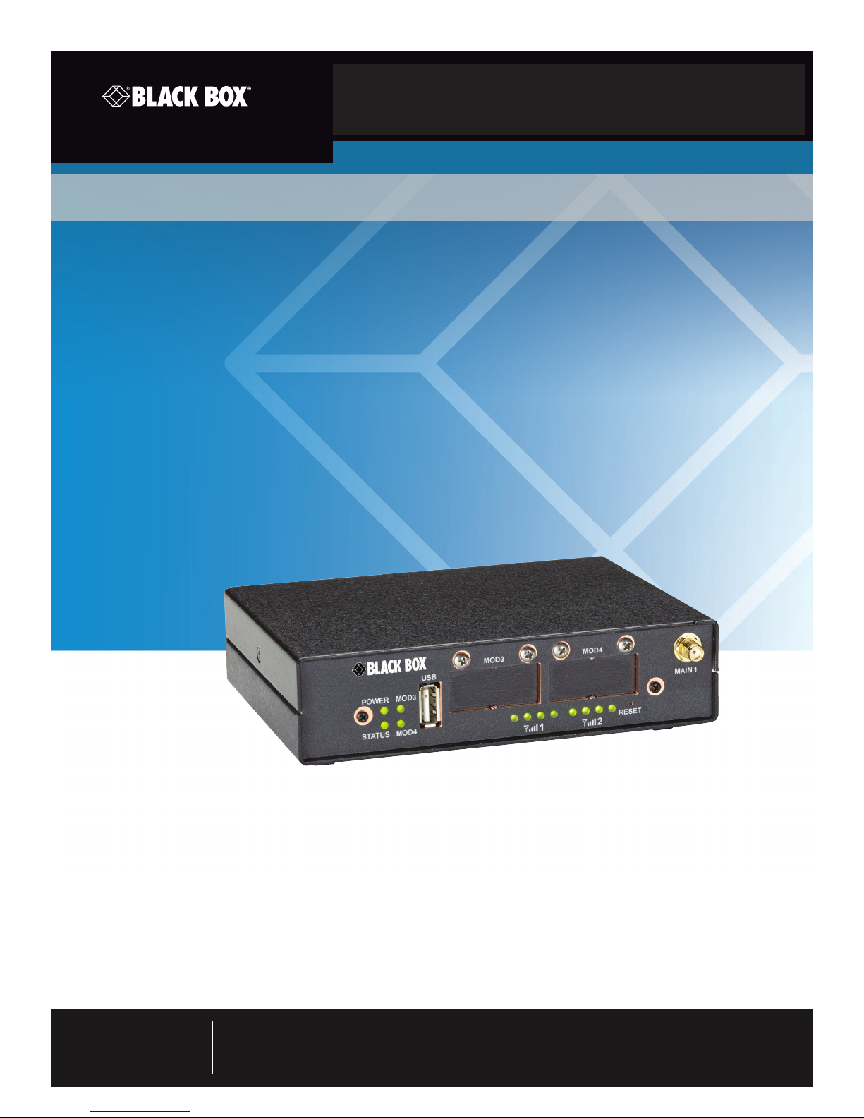
WRT4000 Series Cellular Wireless Routers User Manual
Single box solution for Internet/WAN access, VPN,
firewall, Ethernet switching, and legacy protocol
to IP internetworking.
Approved for user with Verizon®, AT&T®, Sprint®, and international carriers.
Commerical and industrial packages available.
Customer
Support
Information
Order toll-free in the U.S.: Call 877-877-BBOX (outside U.S. call 724-746-5500)
FREE technical support 24 hours a day, 7 days a week: Call 724-746-5500 or fax 724-746-0746
Mailing address: Black Box Corporation, 1000 Park Drive, Lawrence, PA 15055-1018
Web site: www.blackbox.com • E-mail: info@blackbox.com
Page 2

Trademarks Used in this Manual
Trademarks Used in this Manual
Black Box and the Double Diamond logo are registered trademarks of BB Technologies, Inc.
AT&T is a registered trademark of AT&T Inc.
Sprint is a registered trademark of Sprint.
Verizon is a registered trademark of Verizon Wireless, Inc.
Any other trademarks mentioned in this manual are acknowledged to be the property of the trademark owners.
We‘re here to help! If you have any questions about your application
or our products, contact Black Box Tech Support at 724-746-5500
or go to blackbox.com and click on “Talk to Black Box.”
You’ll be live with one of our technical experts in less than 60 seconds.
Page 2
724-746-5500 | blackbox.com
Page 3

FCC and IC RFI Statements
Federal Communications Commission and Industry Canada Radio Frequency Interference
Statements
This equipment generates, uses, and can radiate radio-frequency energy, and if not installed and used properly, that is, in strict
accordance with the manufacturer’s instructions, may cause inter ference to radio communication. It has been tested and found to
comply with the limits for a Class A computing device in accordance with the specifications in Subpart B of Part 15 of FCC rules,
which are designed to provide reasonable protection against such interference when the equipment is operated in a commercial
environment. Operation of this equipment in a residential area is likely to cause interference, in which case the user at his own
expense will be required to take whatever measures may be necessary to correct the interference.
Changes or modifications not expressly approved by the party responsible for compliance could void the user’s authority to
operate the equipment.
This digital apparatus does not exceed the Class A limits for radio noise emis sion from digital apparatus set out in the Radio
Interference Regulation of Industry Canada.
Le présent appareil numérique n’émet pas de bruits radioélectriques dépassant les limites applicables aux appareils numériques
de la classe A prescrites dans le Règlement sur le brouillage radioélectrique publié par Industrie Canada.
Disclaimer:
Black Box Network Services shall not be liable for damages of any kind, including, but not limited to, punitive, consequential or cost of cover damages, resulting
from any errors in the product information or specifications set forth in this document and Black Box Network Services may revise this document at any time
without notice.
724-746-5500 | blackbox.com
Page 3
Page 4

NOM Statement
Instrucciones de Seguridad
(Normas Oficiales Mexicanas Electrical Safety Statement)
1. Todas las instrucciones de seguridad y operación deberán ser leídas antes de que el aparato eléctrico sea operado.
2. Las instrucciones de seguridad y operación deberán ser guardadas para referencia futura.
3. Todas las advertencias en el aparato eléctrico y en sus instrucciones de operación deben ser respetadas.
4. Todas las instrucciones de operación y uso deben ser seguidas.
5. El aparato eléctrico no deberá ser usado cerca del agua—por ejemplo, cerca de la tina de baño, lavabo, sótano mojado o cerca
de una alberca, etc.
6. El aparato eléctrico debe ser usado únicamente con carritos o pedestales que sean recomendados por el fabricante.
7. El aparato eléctrico debe ser montado a la pared o al techo sólo como sea recomendado por el fabricante.
8. Servicio—El usuario no debe intentar dar servicio al equipo eléctrico más allá a lo descrito en las instrucciones de operación.
Todo otro servicio deberá ser referido a personal de servicio calificado.
9. El aparato eléctrico debe ser situado de tal manera que su posición no interfiera su uso. La colocación del aparato eléctrico
sobre una cama, sofá, alfombra o superficie similar puede bloquea la ventilación, no se debe colocar en libreros o gabinetes
que impidan el flujo de aire por los orificios de ventilación.
10. El equipo eléctrico deber ser situado fuera del alcance de fuentes de calor como radiadores, registros de calor, estufas u otros
aparatos (incluyendo amplificadores) que producen calor.
11. El aparato eléctrico deberá ser connectado a una fuente de poder sólo del tipo descrito en el instructivo de operación, o como
se indique en el aparato.
12. Precaución debe ser tomada de tal manera que la tierra fisica y la polarización del equipo no sea eliminada.
13. Los cables de la fuente de poder deben ser guiados de tal manera que no sean pisados ni pellizcados por objetos colocados
sobre o contra ellos, poniendo particular atención a los contactos y receptáculos donde salen del aparato.
14. El equipo eléctrico debe ser limpiado únicamente de acuerdo a las recomendaciones del fabricante.
15. En caso de existir, una antena externa deberá ser localizada lejos de las lineas de energia.
16. El cable de corriente deberá ser desconectado del cuando el equipo no sea usado por un largo periodo de tiempo.
17. Cuidado debe ser tomado de tal manera que objectos liquidos no sean derramados sobre la cubierta u orificios de ventilación.
18. Servicio por personal calificado deberá ser provisto cuando:
A: El cable de poder o el contacto ha sido dañado; u
B: Objectos han caído o líquido ha sido derramado dentro del aparato; o
C: El aparato ha sido expuesto a la lluvia; o
D: El aparato parece no operar normalmente o muestra un cambio en su desempeño; o
E: El aparato ha sido tirado o su cubierta ha sido dañada.
Page 4
724-746-5500 | blackbox.com
Page 5

Table of Contents
Table of Contents
1. Specifications ......................................................................................................................................................................... 8
2. Overview ...............................................................................................................................................................................9
2.1 Description .................................................................................................................................................................... 9
2.2 Features ....................................................................................................................................................................... 10
2.3 What’s Included .......................................................................................................................................................... 11
2.4 Hardware Description .................................................................................................................................................. 12
2.4.1 Front Panel ........................................................................................................................................................ 12
2.4.2 Back Panel .........................................................................................................................................................13
2.4.3 LED Indicators on the Router.............................................................................................................................14
2.4.4 Dual Serial Port Module .................................................................................................................................... 15
2.4.5 10BASE-T/100BASE-T Ethernet Port .................................................................................................................. 16
3. Installation ........................................................................................................................................................................... 17
3.1 Collecting the Items Needed for Installation ................................................................................................................ 17
3.2 Viewing the Ports on the WRT4000 Series Chassis ..................................................................................................... 17
3.3 Replacing the Subscriber Identity Module ...................................................................................................................18
3.4 How to Install or Replace a SIM for a GSM or LTE Module in a WRT4000 Series Router ............................................ 18
3.5 Connecting and Starting the WRT4000 Series Router Chassis ....................................................................................25
3.6 Connecting the WRT4000 Series Router to DC Power ................................................................................................27
3.7 The Next Step ..............................................................................................................................................................32
4. Configuration—General Settings ........................................................................................................................................33
4.1 Using the WRT4000 Router‘s Management System .................................................................................................... 33
4.1.1 Connecting to the WRT4000 Series Cellular Wireless Router .............................................................................33
4.1.2 Logging In .........................................................................................................................................................33
4.1.3 Managing the Browser Display ..........................................................................................................................36
4.2 Navigating the WRT4000 Series Cellular Wireless Router’s Management System .......................................................37
4.2.1 Saving or Discarding Changes ........................................................................................................................... 37
4.2.2 Restarting (Rebooting) the WRT4000 Series Cellular Wireless Router ...............................................................38
4.2.3 Ending the Session ............................................................................................................................................39
4.3 Basic Configuration .....................................................................................................................................................39
4.3.1 Revising Lists in the WRT4000 Series Cellular Wireless Router’s Management System ......................................39
4.3.2 Configuring the Management System Language ..............................................................................................39
4.3.3 Configuring the Device Name and Time of Day ................................................................................................40
4.3.4 Configuring System Logging .............................................................................................................................42
4.3.5 Synchronizing the WRT4000 Series Cellular Wireless Router’s Time of Day ......................................................43
4.3.5.1 Configuring Time-of-Day Synchronization ............................................................................................... 43
4.3.5.2 Selecting Time-of-Day Synchronization ................................................................................................... 45
4.3.6 Overriding the MAC Information ......................................................................................................................46
4.4 Configuration for the Network .................................................................................................................................... 47
4.4.1 DHCP and DNS ..................................................................................................................................................47
4.4.2 Network Hosts .................................................................................................................................................. 49
4.4.3 Routing .............................................................................................................................................................50
4.4.4 Firewall Configuration ....................................................................................................................................... 51
4.4.5 Configuring Traffic Priority ................................................................................................................................54
5. Configuring the Serial Ports .................................................................................................................................................55
5.1 Connecting to the WRT4000 Series Cellular Wireless Router ......................................................................................55
5.2 Configuring a Serial Port .............................................................................................................................................55
724-746-5500 | blackbox.com
Page 5
Page 6

Table of Contents
6. Configuring Chassis Ports .................................................................................................................................................... 63
6.1 Port Interfaces .............................................................................................................................................................63
6.1.1 Configuring a LAN Port .....................................................................................................................................64
6.1.2 Configuring the WAN Port ................................................................................................................................ 67
7. Configuring a MultiWAN for the WRT4000 Series Cellular Wireless Router ........................................................................ 70
7.1 Use of a MultiWAN ..................................................................................................................................................... 70
7.2 Configuring a MultiWAN .............................................................................................................................................71
8. Virtual Private Networks ...................................................................................................................................................... 80
8.1 VPN Configuration in the WRT4000 Series Cellular Wireless Router ...........................................................................80
8.1.1 Configuring VPNs in the WRT4000 Series Cellular Wireless Router ...................................................................80
8.1.2 Starting the Tunnel ............................................................................................................................................ 85
8.2 Testing and Tracking VPN Connections .......................................................................................................................85
8.2.1 Testing VPN Connections ..................................................................................................................................85
8.2.2 Tracking VPN Connections ................................................................................................................................87
8.2.2.1 Tracking Specific Information ..................................................................................................................87
8.2.2.2 Tracking General VPN Activity ................................................................................................................90
8.3 VPN Basics ................................................................................................................................................................... 92
8.3.1 A Simple Virtual Private Network ......................................................................................................................93
8.3.2 Tunnel Modes ...................................................................................................................................................94
8.3.2.1 Tunnel Initiation ...................................................................................................................................94
8.3.2.2 Tunnel Termination .............................................................................................................................. 94
8.3.2.3 Tunnel Passthrough .............................................................................................................................95
8.3.3 Tunnel Support .................................................................................................................................................96
8.3.3.1 Tunnel Sharing .....................................................................................................................................96
8.3.3.2 Tunnel Switching .................................................................................................................................96
8.3.3.3 Split Tunneling ..................................................................................................................................... 97
8.3.4 Internet Key Exchange.......................................................................................................................................97
8.3.4.1 Perfect Forward Secrecy ......................................................................................................................97
8.3.4.2 IKE Version 1 ....................................................................................................................................... 97
8.3.4.3 IKE Version 2 .......................................................................................................................................98
8.4 Developing a Virtual Private Network ........................................................................................................................ 102
8.4.1 VPN Configuration Plan ................................................................................................................................... 102
8.4.2 Automatic Keying ...........................................................................................................................................104
8.4.3 Sample Configuration for a Remote User........................................................................................................105
9. Monitoring the WRT4000 Router ...................................................................................................................................... 107
9.1 Monitoring ................................................................................................................................................................ 107
9.1.1 Collection of Statistics ...................................................................................................................................... 108
9.1.2 Graphs ..............................................................................................................................................................111
9.1.2.1 Displaying Graphs Ending at the Current Time .....................................................................................111
9.1.2.2 Displaying Graphs Beginning at the Current Time ............................................................................... 112
9.1.3 Routing Information ....................................................................................................................................... 116
9.1.4 Pings and Other Network Diagnostics ............................................................................................................ 116
9.1.5 Firewall Statistics ............................................................................................................................................. 118
9.1.6 System Processes ............................................................................................................................................ 119
9.1.7 Logs ................................................................................................................................................................ 120
Appendix A. Setting the WRT4000 Series Cellular Wireless Router’s APN .............................................................................. 124
Appendix B. Glossary .............................................................................................................................................................. 126
Appendix C. Basic Safety Guidelines ...................................................................................................................................... 140
Page 6
724-746-5500 | blackbox.com
Page 7

Chapter 1: Specifications
1. Specifications
Management SNMP v3,
GUI Web management,
Telnet,
SSH (secure shell),
Syslog
Security Stateful inspection firewall,
IEEE 801.22i (WPA2, RSN),
DMZ LAN port,
NAT (Network Address Translation),
SSL / TLS1,
SSH (Secure Shell),
IP Sec (RFC 2401) with AES 256 and 3DES,
Generic Router Encapsulation GRE (RFC 1701),
Internet Key Exchange (IKE) RFC-2409
Serial Data Support Industrial models (WRT4001A–WRT4004A, WRT4001A-DC–WRT4004A-DC): Up to (2)
serial ports supporting TIA RS-485, RS-232
NOTE: Contact Black Box Technical Support at 724-746-5500 or info@blackbox.com for
additional protocols.
Transport Protocols WAN:
IP over Ethernet (compatible with MPLS services),
Asynchronous PPP,
Synchronous PPP,
MLPPP,
PPPoE,
Selective Layer Encryption (SLE) for VPN optimization (patented);
IP:
IP versions 4 and 6,
IP routiing (RIP v1/v2), OSPF, BGP, or static routing,
DHCP client/server/BootP/Relay,
IP QoS and traffic prioritization,
IP fragmentation/assembly,
IP routing over VPN; TCP ad UDP,
802.1q VLAN tagging,
Virtual Redundant Routing Protocol (VRRP) between two routers,
Dead Peer Detection
User Controls Front panel: Reset switch
Connectors All models (includes industrial and commericial models):
Front panel:
(1) USB host port,
(1) main antenna connector for internal wireless module;
Back panel:
(1) auxiliary antenna connector for internal wireless module,
(1) 10/100 Mbps Ethernet RJ-45 (WAN),
(4) RJ-45 10/100 Mbps switched Ethernet LAN ports,
(1) 5-VDC input (from AC line-power adapter),
WRT4001A-DC–WRT4004A-DC: (1) connector for 24-VDC input;
WRT4001A–WRT4004A, WRT4001A-DC–WRT4004A-DC industrial units only include:
(2) RJ-45 (RS-232/RS-485)
724-746-5500 | blackbox.com
Page 7
Page 8

Chapter 1: Specifications
1. Specifications (continued)
Indicators Front panel:
(4) LEDs for module, system status, and power;
(4) LEDs for wireless signal strength indication for one cellular module,
(4) LEDs not used at this time;
Back panel:
(4) TX, (4) LNK/RX LEDs for RJ-45 LAN ports,
(1) TX, (1) LNK/RX LEDs for WAN port
Environmental Temperature Tolerance:
Operating:
Industrial Hardened: -40 to +185° F (-40 to +85 C),
Extended Temperature Commercial: -4 to 149 F (-20 to +65 C);
Humidity: 5 to 95%, noncondensing
Power DC models: 24 VDC, 13 watts maximum,
AC models: 100–240 VAC, autoranging adapter, 50–60 Hz, 5 VDC, 3 A output,
15 W max.
Dimensions 1.6"H x 5.7"W x 4"D (4 x 14.5 x 10 cm)
Weight Metal case (WRT4001A–WRT4004A, WRT4001A-DC–WRT4004A-DC:
0.85 lb. (0.39 kg);
Plastic case (WRT4011A–WRT4014A):
0.75 lb. (0.34 kg)
Approvals FCC Part 15,
EN55011/CISPR II,
IEC 61850-3,
IEEE 1613;
®
UL
/CSA 60950-1,
CAN/CSA-C22.2 No. 60950-1-03,
EN 60950-1
Page 8
724-746-5500 | blackbox.com
Page 9

Chapter 2: Overview
2. Overview
2.1 Description
The WRT4000 Series Router provides speed, capacity, and flexibility for wired, optical fiber, and cellular uplinks; complete remote
management; and support for current and legacy data protocols.
The WRT4000 Series Router chassis is designed to operate in industrial or commercial environments with a wide range of
ambient temperatures. The industrial versions have a tight all-metal enclosure that resists dust, moisture, and electromagnetic
interference (EMI). The commercial versions have a plastic enclosure that resists dust, moisture, and EMI.
The WRT4000 Series Router has expanded memory and a high-speed processor that allow it to handle multiple ports and highspeed network connections while converting protocols, routing packets, and applying firewall rules and other security measures.
With an optional encryption-chip module, a single WRT4000 Series Router can terminate more than 1,000 virtual private
network (VPN) tunnels without affecting other features. One internal cellular wireless module is standard on the industrial and
commercial routers (all part numbers). The industrial routers (part numbers WRT4001A–WRT4004A and WRT4001A-DC–
WRT4004A-DC) also have a dual-port serial expansion module installed in one of the expansion slots.
Up to two antennas handle 3G/4G/LTE cellular and advanced Wi-Fi.
There is no cooling fan or other moving parts. All models are built on the same hardware platform.
The WRT4000 Series Router requires minimal power. Typical configurations draw less than 13 W. The power source options are:
• an AC power supply unit (PSU)
• a DC input line, at several voltages
The power input sources provide 5 VDC to the chassis.
NOTE: A DC power input can form a redundant pair with an AC power input: One is the chassis’s primary input power source,
and the other source provides power if the primary source is down.
Table 2-1. Available models, internal modules installed.
Part Number Product Name/Description
WRT40 01A VZ 4G/LTE Industrial Router, Metal Case, AC Power
WRT40 02A VZ 3G Industrial Router, Metal Case, AC Power
WRT40 03A ATT 4G LTE/HSPA+ Industrial Router, Metal Case, AC Power
WRT40 0 4A Sprint 3G Industrial Router, Metal Case, AC Power
WRT4001A-DC VZ 4G/LTE Industrial Router, Metal Case, 24 VDC Power
WRT4002A-DC VZ 3G Industrial Router, Metal Case, 24 VDC Power
WRT4003A-DC ATT 4G LTE/HSPA+ Industrial Router, Metal Case, 24 VDC Power
WRT4004A-DC Sprint 3G Industrial Router, Metal Case, 24 VDC Power
WR T4 011A VZ 4G/LTE Commercial Router, Plastic Case, AC Power
WRT4012 A VZ 3G Commercial Router, Plastic Case, AC Power
WRT4013A ATT 4G LTE/HSPA+ Commercial Router, Plastic Case, AC Power
WRT4014A Sprint 3G Commercial Router, Plastic Case, AC Power
724-746-5500 | blackbox.com
Page 9
Page 10

Chapter 2: Overview
Table 2-2. Optional accessories.
Part Number Product Name/Description
WRT4000-DIN Optional DIN Rail Mounting Kit Available for Metal Case Packages
WRT4000-PM Optional Panel Mount Kit Available for Metal Case Packages
WRT4000-RM Optional Right-Angle Bracket Mounting Kit Available for Metal Case Packages
WRT4000-ANT Optional Indoor 3G/4G Antenna
WRT4000-ANT-KIT Optional Indoor Magnetic Pedestal, 8-Foot Cable Antenna
2.2 Features
• Commercial or industrial versions with redundant power sources include: 120-VAC or 24-VDC.
• Provides service over any port, any network, at any time, including cellular 3G, 4G, LTE, and Ethernet.
• Automatic failover with traffic load sharing between wireline and wireless links.
• VPN IP Security (IPSec), AES 256 and 3DES, SSL/ TLS and SSH.
• Operation, administration, and management (OA&M) with Web-based GUI management.
Industrial Routers
• Metal case resists dust, moisture, and EMI.
• Temperature Tolerance:
Operating:
Industrial Hardened: -40 to +185° F (-40 to +85° C);
Humidity: 5 to 95%, noncondensing
Commercial Routers
• Plastic case
• Temperature Tolerance:
Operating: Extended Temperature Commercial: -4 to +149° F
(-20 to +65° C);
Humidity: 5 to 95%, noncondensing
Page 10
724-746-5500 | blackbox.com
Page 11

Chapter 2: Overview
2.3 What’s Included
• WRT4000 Series Cellular Wireless Router
• AC or DC power supply
• (1) to (2) antennas
• Quick Start Guide
The full user manual/installation guide can be downloaded from the Black Box Web site.
To download from the Web site:
1. Go to www.blackbox.com
2. Enter the part number (for example, WRT4001A) in the search box:
3. Click on the “Resources” tab on the product page, and select the document you wish to download.
724-746-5500 | blackbox.com
Pa g e 11
Page 12
Chapter 2: Overview
2.4 Hardware Description
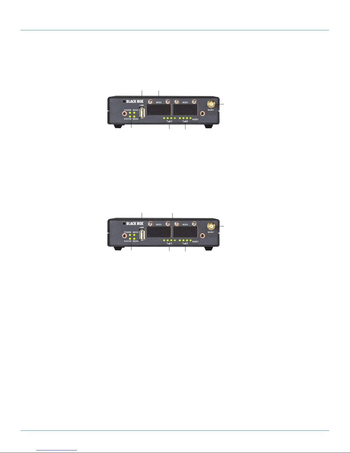
2.4.1 Front Panel
*Industrial model: left slot: inst alled
USB
Port
card with ( 2) serial p orts
Main antenna port for
internal wireless module
LEDs for
Power and
Status
LEDs for signal
strength for
internal wireless
module
LEDs (not
used)
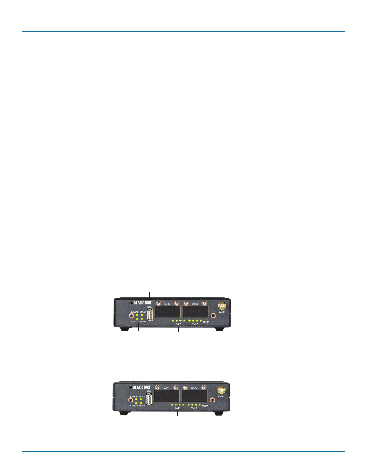
Figure 2-1. WRT4001A–WRT4004A, WRT4001A-DC–WRT4004A-DC Series Router front panel.
*NOTE: The industrial routers (part numbers WRT4001A–WRT4004A and WRT4001A-DC–WRT4004A-DC) have one dual-port
serial module pre-installed in one of the empty expansion slots. The commerical models (WRT4011A–WRT4014A) do not
have any expansion modules installed. Additional expansion modules for the routers are not available at this time, but
may be included in a future product release.
USB
*Commercial model: empty slot s
Port
Main antenna port for
internal wireless module
LEDs for
Power and
Status
LEDs for signal
strength for
internal wireless
module
LEDs (not
used)
Figure 2-2. WRT4011A–WRT4014A Series Router front panel.
Page 12
724-746-5500 | blackbox.com
Page 13
Chapter 2: Overview
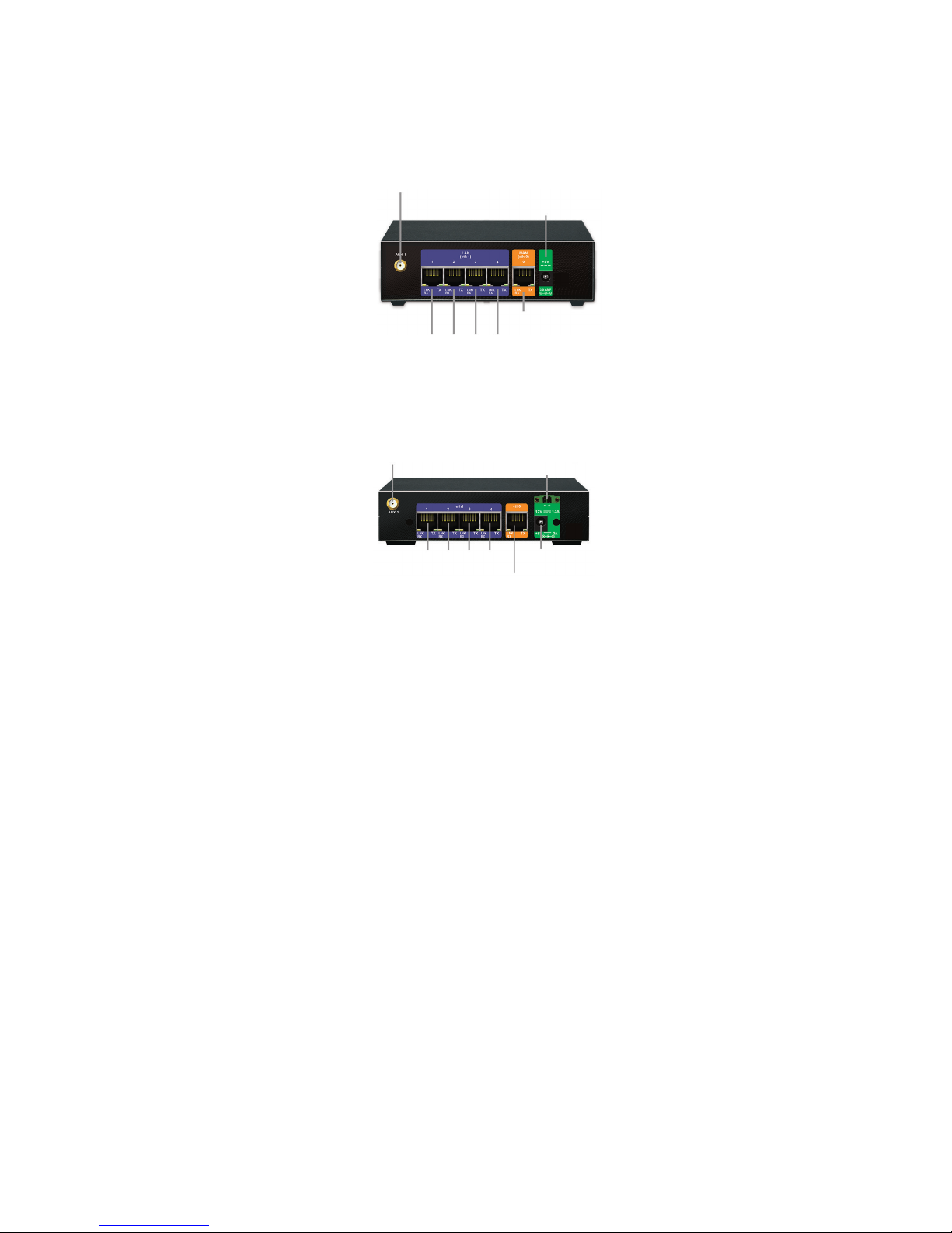
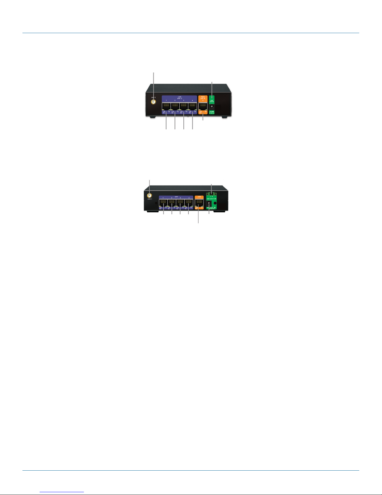
2.4.2 Back Panel
Auxiliary antenna port
for internal wireless module
Ethernet L AN ports (eth 1)
Figure 2-3. WRT4000 Series Router back panel, AC power versions (WRT4001A–WRT4004A, WRT4011A–WRT4014A).
Auxiliary antenna port
for internal
wireless module
Port for AC p ower
adapter input
Ethernet WA N port ( eth 0)
DC power connector
Ethernet L AN ports (eth 1) Port for AC power
Ethernet WA N port ( eth 0)
adapter input
Figure 2-4. WRT4000 Series Router back panel, DC power versions (WRT4001A-DC–WRT4004A-DC).
724-746-5500 | blackbox.com
Page 13
Page 14

Chapter 2: Overview
Table 2-3. Components on the WRT4000 Series Cellular Wireless Router.
Number in Fig. 2-1–2-4 Component Description
1 (1) Power LED Lights when power to the unit is on
2 (3) LEDs For module and system status
3 (1) USB port
4 (2) external antenna connectors For internal wireless ports
5 (2) groups of (4) LEDs For cellular wireless signal strength
6 (1) Reset switch For default software/configuration load
7 (2) empty slots Currently not used
8 (2) external auxiliary antenna
connectors
9 (1) RJ-45 port 10/100 Ethernet (WAN) port
10 (4) RJ-45 ports 10/100 switched Ethernet (LAN)
11 (1) 5-VDC input port From AC power adapter
NOTE: The WRT4000 Series Router chassis that uses DC power also has a 24-VDC port.
For factory-installed internal wireless modules
(cellular 3G, EVDO, or 4G; Wi-Fi; or Bluetooth)
2.4.3 LED Indicators on the Router
Each group of 4 LEDs indicates the status of a connection to a cellular wireless network and the strength of signals from that
network:
• The number of LEDs that light up (1 to 4 lights) indicates the signal strength.
• 1 to 4 steady (unblinking) LEDs indicate that the port is connected to a cellular wireless network.
• 1 to 4 blinking LEDs indicate that a network is available but that the port does not have an IP address. (In this case, configure an
IP address for the port, so that the port can connect to the network. See Chapter 4, Configuration.
The following general rules apply to the WRT4000 Series Router’s LEDs:
• A lit green Power LED indicates that the unit is being supplied with power.
• A lit green Link LED indicates that there is a connection to another device, including an Ethernet hub or switch.
• A flashing Alarm LED indicates that the WRT4000 Series Router has detected an alarm, or that the system needs attention, or
that power to the system has failed.
Table 2-4 describes the LEDs on the WRT4000 Series Router chassis.
Page 14
724-746-5500 | blackbox.com
Page 15
Chapter 2: Overview
Table 2-4. General Status LEDs definitions.
LED Color Description
Power Green Unit is receiving power.
Green (flashing) A port has an alarm or the system needs attention.
Off Unit is not receiving power.
Status Green Connected to management terminal (or to carrier, if the port is used for
data).
Off Not connected.
WAN port (Ethernet port) Green Connected to WAN gateway (Ethernet hub or switch).
Off Connection to WAN gateway has failed.
LAN port (Ethernet port) Green Connected to a supported Ethernet device or connected to the LAN
(connected to an Ethernet hub or switch).
Off Not connected to the LAN.
Cellular Green (not flashing) Connected to a cellular wireless carrier.
Green (Flashing) A cellular wireless network is sending a signal, but the wireless port has
not been configured.
Off Not activated. The device has not been authenticated for a wireless
carrier and is not receiving a signal.
2.4.4 Dual-Serial Port Module
The industrial routers (part numbers WRT4001A–WRT4004A and WRT4001A-DC–WRT4004A-DC) have one dual-port serial
module pre-installed in one of the empty expansion slots. No additional expansion modules are available at this time.
Figure 2-5 shows the dual serial-port module for the industrial routers (WRT4001A–WRT4004A and WRT4001A-DC–WRT4004ADC).
NOTE: Commercial WRT4000 Series Routers (WRT4011A–WRT4014A) do not have the serial module.
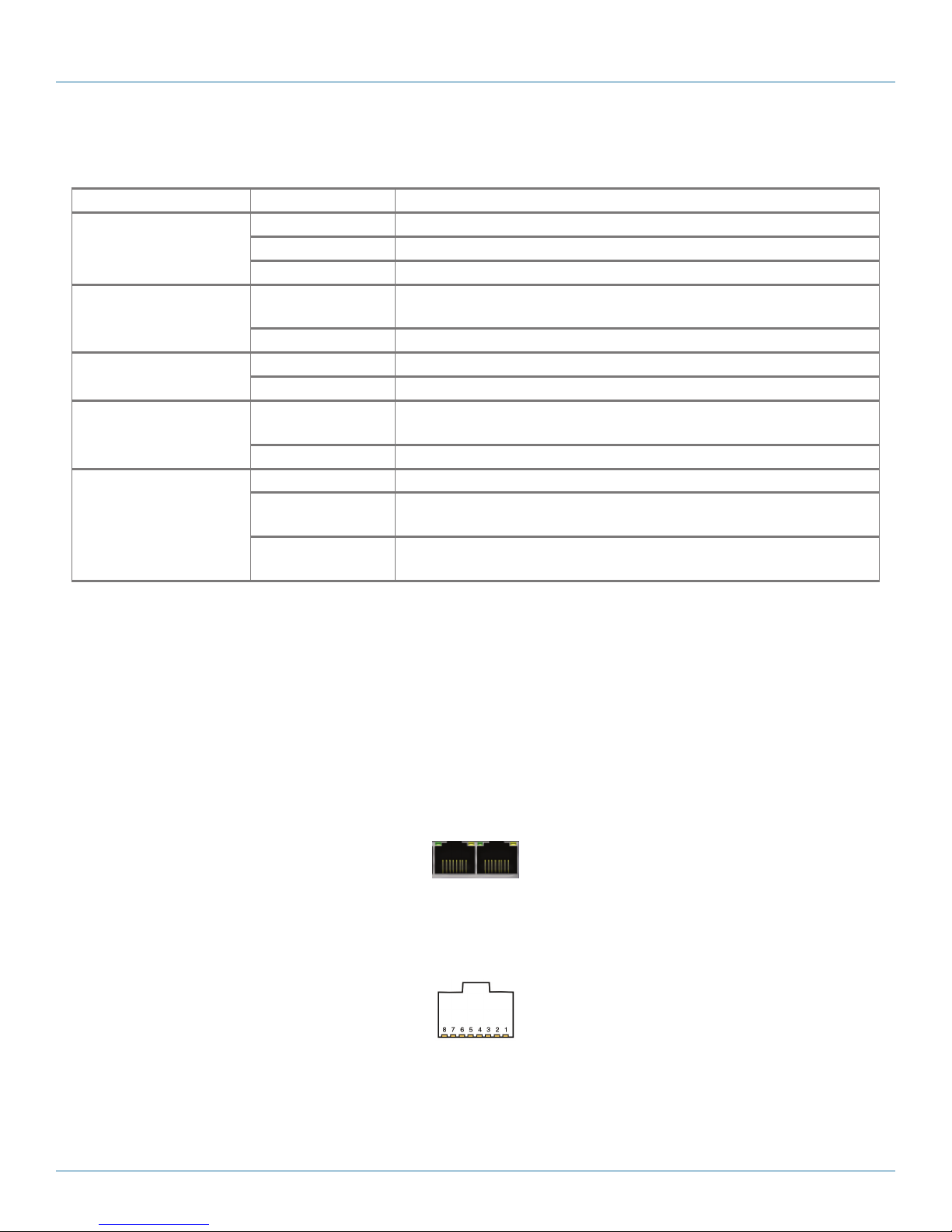
As the name indicates, this module provides two serial ports. The serial ports use RJ-45 connections.
Figure 2-5. Dual serial port module (present in industrial models).
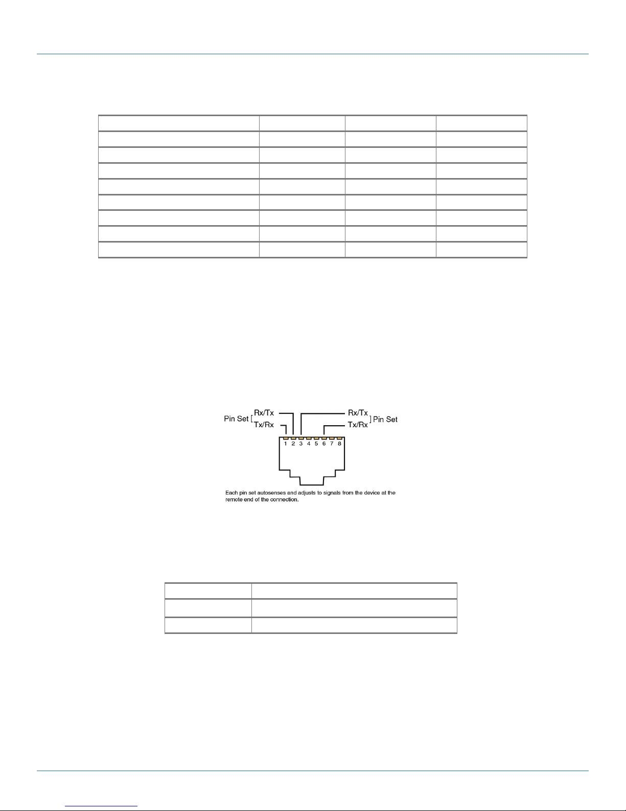
Figure 2-6 shows the pin locations on an RJ-45 Ethernet port. Table 2-5 lists the pin configuration for the WRT4000 Series
Router’s RJ-45 serial ports.
Figure 2-6. Pin locations for female RJ-45 serial connector.
724-746-5500 | blackbox.com
Page 15
Page 16
Chapter 2: Overview
Table 2-5. RJ-45 serial port pin configuration.
RJ-45 Pin Number in Fig. 2-6 RS-232 RS485HD RS485FD
1 DSR/RI (O) TX/RX+ (BI) RXD+ (O)
2 DCD (O) TX/RX- (BI) RXD- (O)
3 DTR ( I ) N/A TXD- (I)
4 SGND SGND SGND
5 RD (O) DSR (O) DSR (O)
6 TD (I) N/A TXD+ (I)
7 CTS (O) CTS (O) CTS (O)
8 RTS (I) RTS (I) RTS (I)
The serial port options are RS-232 DCE, RS-485 half-duplex, and RS-485 full-duplex. The supported protocols (selectable in software) are asynchronous encapsulation and telnet terminal.
2.4.5 RJ-45 10BASE-T/100BASE-T Ethernet Port
Figure 2-7 shows the pin locations on an RJ-45 Ethernet port. Table 2-6 lists the pin configuration for the WRT4000 Series
Router’s 10/100BASE-T Ethernet ports.
NOTE: These ports are present on both industrial and commercial routers.
Figure 2-7. Pin locations for female RJ-45 Ethernet connector.
NOTE: The WRT4000 Series Router senses the pin configuration at the remote end of the connection and sets its own pin
configuration accordingly.
Table 2-6. 10BASE-T/100BASE-T Ethernet port pin configuration.
Pin Set Description
1 and 2 Tx or Rx
3 and 6 Rx or Tx
NOTES:
1. Unused pins are not listed.
2. The WRT4000 Series Router Ethernet connectors are autosensing and will adjust to the signals from the device at the remote
end of the connection.
Page 16
724-746-5500 | blackbox.com
Page 17
Chapter 3: Installation
3. Installation
3.1 Collect the Items Needed for Installation
1. Get everything out of the shipping box. It should contain:
• A Quick Installlation Guide
• WRT4000 Series Cellular Wireless Router
• DC connector set or AC power adapter
• Antennas (ordered separately)
2. Get additional items required to install the WRT4000 Series Cellular Wireless Router. You will need:
• Computer with Web-browsing software
• Ethernet cable
• Subscriber Identity Module (SIM)
3
• Cellular wireless network account
1
2
3
NOTES:
1
This quick discussion assumes that there will be one embedded cellular module and the miniPCIe slot will not be in use.
2
JavaScript must be enabled in the Web browser.
3
The embedded cellular module must have a cellular wireless network account and a Subscriber Identity Module (SIM) for that
account. Order each SIM from a cellular wireless network provider. SIMs are not shipped with the Router.
3.2 Viewing the Ports on the WRT4000 Series Router Chassis
WRT4001A–WRT4004A, WRT4001A-DC–WRT4004A-DC Series
Industrial model: left slot: installed card
LEDs for
Power and
Status
WRT4011A – W R T4 014A Series
USB
Port
USB
Port
(not shown) with (2) serial ports
LEDs for signal
strength for
internal wireless
module
Commercial m odel: empty slot s
LEDs (not
used)
Main antenna port for
internal wireless module
Figure 3-1. WRT4000 Series Router front panel.
internal wireless module
LEDs for
Power and
Status
LEDs for signal
strength for
internal wireless
module
LEDs (not
used)
724-746-5500 | blackbox.com
Main antenna port for
Page 17
Page 18
Chapter 3: Installation
Figure 3-2. WRT4000 Series Router back panel, AC power (WRT4001A–WRT4004A, WRT4011A–WRT4014A).
Auxiliary antenna port
for internal
wireless module
Ethernet L AN ports (eth 1)
Antenna port
Port for AC p ower
adapter input
Ethernet WA N port ( eth 0)
(not used)
Auxiliary antenna port
for internal
wireless module
Ethernet L AN ports (eth 1) Port for AC power
DC power connector
Ethernet WA N port ( eth 0)
Antenna port
(not used)
adapter input
Figure 3-3. WRT4000 Series Router back panel, DC power and AC power (WRT4001A-DC–WRT4004A-DC).
3.3 Replacing the Subscriber Identity Module
The WRT4000 Series Router holds one wireless card. You will need to put a Subscriber Identity Module (SIM) into place for GSM
cards and LTE cards. (A SIM is sometimes called a GSM or LTE smartcard.)
A GSM cellular wireless module or an LTE cellular wireless module supports a removable SIM to identify the user to the GSM or
LTE network. When you order your WRT4000 Series Router’s wireless card, you specify which carrier and network the card will
use. If you specify a GSM or LTE module, you must order a SIM from the selected GSM or LTE carrier. The carrier provides a SIM
with the carrier’s chip.
NOTE: The WRT4000 Series Router is not a traveling device, so you will not need SIMs for different countries. However, if you
change wireless providers, the WRT4000 Series Router’s GSM or LTE card will need a SIM from the new provider. To install
a new SIM, use the following procedure.
3.4 How to Install or Replace a SIM for a GSM or LTE Module in the WRT4000 Series Router
WARNING: Follow proper procedures and observe all precautions to guard against electrical shock and to protect the device
against electrostatic discharge (ESD) when removing or installing modules in an WRT4000 Series Router device. (For
example, keep the device grounded, wear an ESD wrist-strap, and so forth.) For more information, see the Basic
Safety Guidelines.
Allow only qualified service personnel to install and maintain this equipment.
NOTE: After you replace the SIM, you must activate the SIM’s GSM or LTE card in the carrier network. The former activation of
the card (with its former SIM) is no longer valid.
1. Unplug the WRT4000 Series Router device’s power supply from the power source.
CAUTION: To prevent electrical shock, turn off power to the equipment before disconnecting cables.
2. Disconnect all network connections.
3. Place the chassis on a flat, stable surface.
Page 18
724-746-5500 | blackbox.com
Page 19
Chapter 3: Installation
4. Do the following:
a. Turn the chassis over so that it is resting on its top.
b. Remove the screws from the sides of the chassis, and lift the chassis shell off the bottom of the chassis.
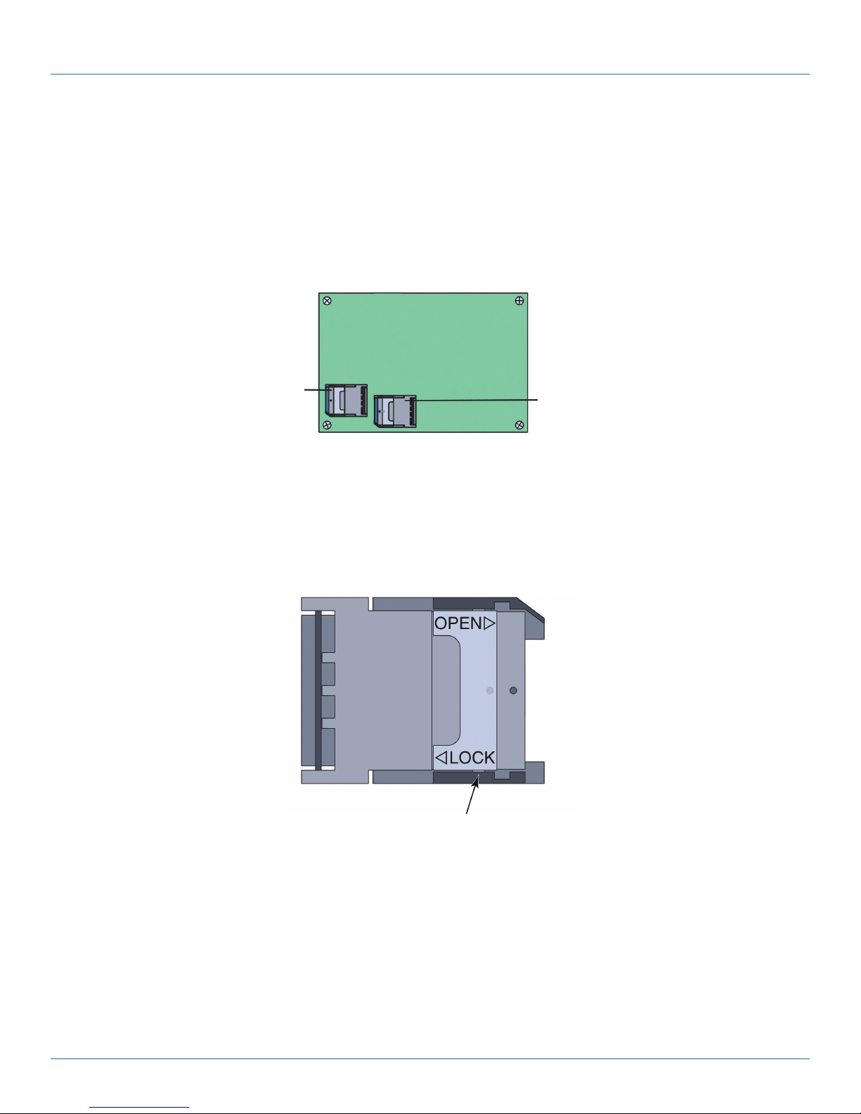
5. Locate the SIM sockets on the bottom of the WRT4000 Series Router motherboard (Figure 3-4).
NOTE: The SIM sockets shown in this document are generic representations. The SIM sockets on your WRT4000 Series Router
may look different.
Edge of board against front of chassis
SIM socket for
embedded GSM
or LTE module
Edge of board against back of chassis
SIM socket
(not used)
Figure 3-4. SIM on Bottom of WRT4000 Series Router Motherboard.
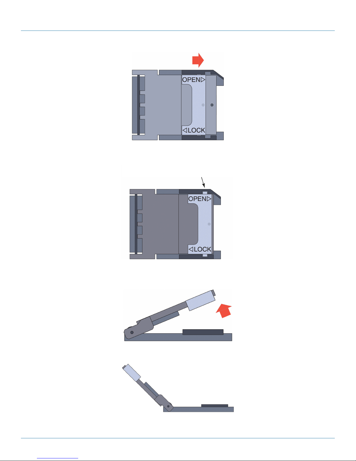
6. A SIM socket might have a latch to unlock or lock its door. The latch should be in the locked position (Figure 3-5).
NOTE: If the SIM sockets in your WRT4000 Series Router do not use locks, then the SIM doors themselves snap securely into
place.
When the SIM holder’s door is locked, the flanges
of the lock are under the catches.
Figure 3-5. Empty SIM Socket (Top View), with Latch in Locked Position.
7. For one SIM socket, do the following:
a. Slide the metal latch toward the end of the SIM socket’s door (Figure 3-6).
You might hear a slight click when it unlatches (Figure 3-7).
724-746-5500 | blackbox.com
Page 19
Page 20
Chapter 3: Installation
Figure 3-6. Unlocking the SIM Socket’s Door.
When the SIM holder’s door is locked, the flanges
of the lock clear the cutouts.
Figure 3-7. Unlocked SIM Socket.
b. Swing the hinged door up (Figure 3-8), so that the SIM socket is open (Figure 3-9 and Figure 3-10).
Figure 3-8. Opening the SIM Socket’s Door (Side View)
Figure 3-9. Partially Opened Empty SIM Socket (Side View).
Page 20
724-746-5500 | blackbox.com
Page 21
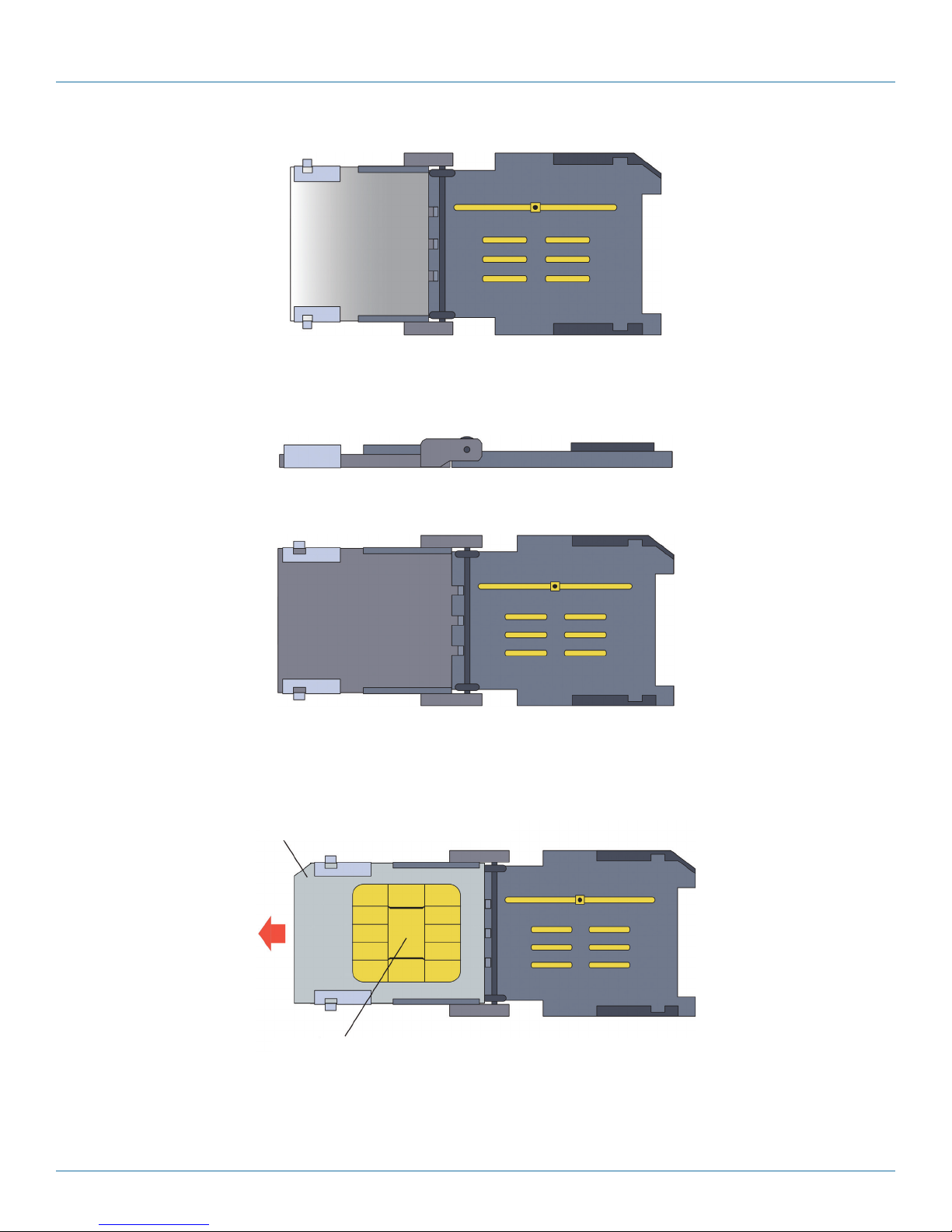
Figure 3-10. Partially Opened Empty SIM Socket (Top View).
NOTE: The door can swing open 180 degrees (Figure 3-11 and Figure 3-12).
Figure 3-11. Fully opened empty SIM socket (side view).
Chapter 3: Installation
Figure 3-12. Fully opened empty SIM socket (top view).
c. If a SIM from a former provider is in the door, slide it out (Figure 3-13). (Be careful not to touch the contact pad.) Put the old
SIM into an anti-static bag.
Back view of SIM from previous GSM carrier
Contact pad (All of the gold area on the back of the SIM is part of the contact pad.)
Figure 3-13. Sliding an Old SIM out of the SIM Socket.
724-746-5500 | blackbox.com
Page 21
Page 22
Chapter 3: Installation
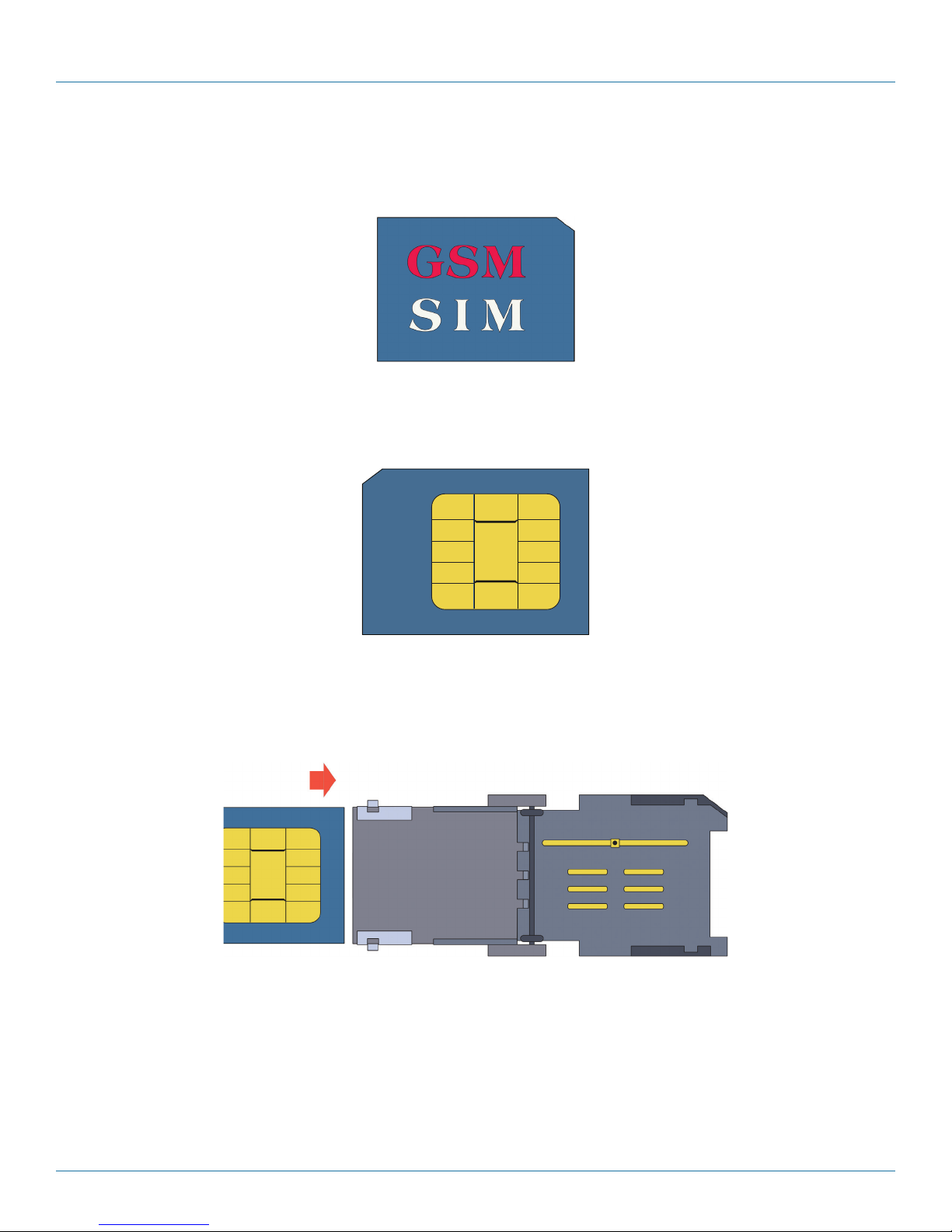
d. Open the package holding the new SIM. Hold the new SIM by its edges and take it out of the package. (See Figure 3-14.)
NOTE: The SIM has a notch out of one corner, to fit into the beveled corner of the SIM socket. The SIM fits into the socket in only
one way that allows the SIM door to close.
Figure 3-14. Front of SIM (Sample Logo).
CAUTION: Be careful not to touch the contact pad on the back of the SIM (see Figure 3-15).
Figure 3-15. Contact pad on back of SIM.
e. Make sure the SIM’s contact pad will face the contacts in the bottom plate of the SIM socket when the door is closed. Then
slide the new SIM into the door (Figure 3-16 through Figure 3-18). (The door has guides to hold the card in place.)
Figure 3-16. Inserting the New SIM into the SIM Socket’s Door.
Page 22
724-746-5500 | blackbox.com
Page 23
Chapter 3: Installation
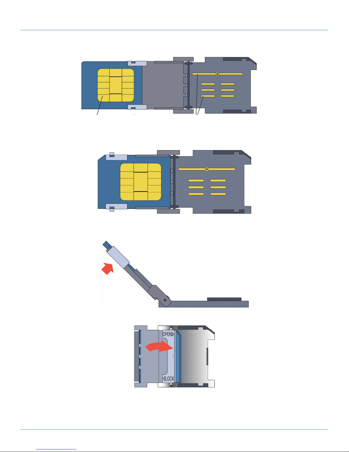
Contact pad on back of SIM
Figure 3-17. SIM Partially Inserted into the SIM Socket’s Door.
Figure 3-18. SIM Fully Inserted into the SIM Socket’s Door.
f. Gently swing the door shut (Figure 3-19 through Figure 3-21).
Contact pad on bottom plate of SIM socket
Figure 3-19. Closing the SIM Socket, at about 45 Degrees of Rotation (Side View).
Figure 3-20. Closing the SIM Socket, at about 135 Degrees of Rotation (Top View).
724-746-5500 | blackbox.com
Page 23
Page 24

Chapter 3: Installation
Figure 3-21. Closed SIM Socket with New SIM (Side View, Door Not Yet Locked).
CAUTION: The SIM fits into the SIM socket in only one way. When you gently swing the door shut, you will see whether the
notched corner of the SIM fits into the socket’s beveled corner.
If the SIM is not in the correct position, its notched corner will not match the beveled corner in the SIM socket, and the door will
not close (Figure 3-22 and Figure 3-23).
If the SIM is positioned
incorrectly, the SIM socket’s
door will not close
Figure 3-22. SIM in Incorrect Position (Top View).
If the SIM is positioned
incorrectly, the SIM socket’s
door will not close
Figure 3-23. SIM in Incorrect Position (Side View).
g. If the SIM is not in the correct position, remove the SIM and replace it in the correct position (Figure 3-24).
If the SIM is positioned correctly,
the SIM socket’s door can close
Figure 3-24. SIM in the Correct Position (Top View).
Page 24
724-746-5500 | blackbox.com
Page 25
Chapter 3: Installation
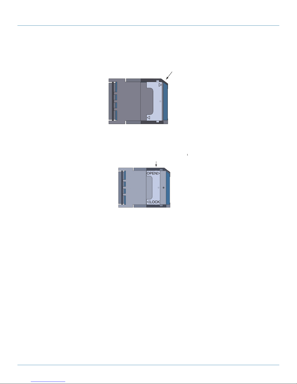
h. When the SIM is correctly positioned and the SIM socket’s door is fully closed, slide the metal lock toward the center of the
door (Figure 3-25) until it stops (Figure 3-26).
When the SIM is positioned correctly,
When the SIM is positioned correctly,
the SIM socket’s door can close
the SIM socket's door can close.
OPEN
SIM
Maker
LOCK
Figure 3-25. Locking the SIM Socket’s Door (Top View).
When the SIM socket’s door is locked, you will
not see the flanges of the lock because they
are under the socket’s catches.
Figure 3-26. Locked SIM Socket with New SIM (Top View).
8. You have completed replacement of the SIM for the GSM or LTE card.
9. Reassemble the WRT4000 Series Router chassis, and turn the chassis right-side up.
3.5 Connecting and Starting the WRT4000 Series Router Chassis
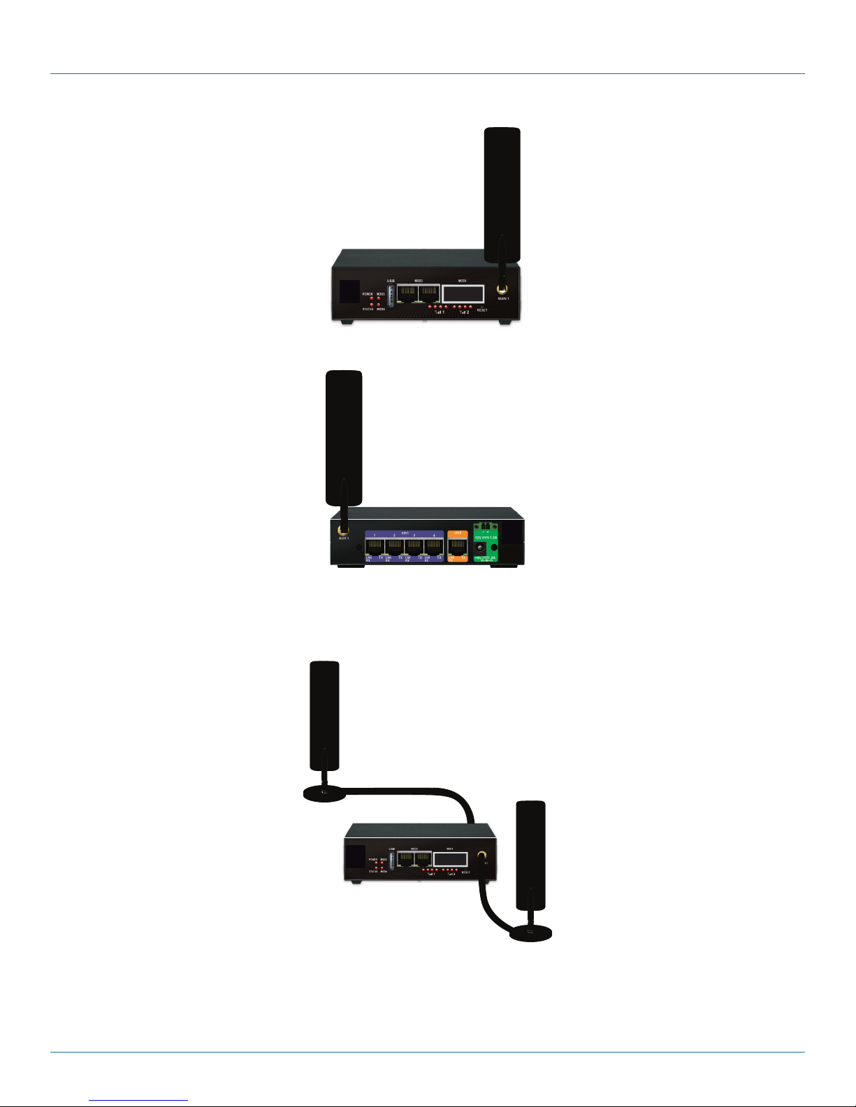
1. Attach antennas to the antenna ports on the front (MAIN 1) and back (AUX 1) of the chassis, as shown in Figure 3-27 and
Figure 3-28.
724-746-5500 | blackbox.com
Page 25
Page 26
Chapter 3: Installation
Figure 3-27. Front of WRT4000 Series Router Chassis, with Antennas.
Figure 3-28. Back of WRT4000 Series Router Chassis, with Antennas.
NOTE: Figure 3-29 shows an alternate approved installation of an WRT4000 Series Router chassis. Two cellular wireless antennas
are on magnetic mounts. Two 10-foot-long cables connect the antennas to the WRT4000 Series Router’s MAIN 1 and AUX
1antenna ports.
Figure 3-29. Approved installation.
NOTE: Each wireless card uses two antennas, for data diversity:
• The antenna ports marked MAIN 1 and AUX 1 support the internal cellular wireless card.
2. Connect the WRT4000 Series Router’s network connections.
Page 26
724-746-5500 | blackbox.com
Page 27
Chapter 3: Installation
3. Connect the WRT4000 Series Router’s power supply. See the instructions below in Section 3.6.
• The device powers up.
3.6 Connecting the WRT4000 Series Router to DC Power
This section describes assembly and use of a DC power connector for the WRT4000 Series Cellular Wireless Router chassis. The
detailed steps also include connection to AC power.
NOTE: If you do not need or want a detailed description of this procedure, see the WRT4000 Series Cellular Wireless Router Quick
Start Guide.
CAUTION: If you have an WRT4000 Series Router chassis that can use both DC and AC power, it is important to follow these
steps to connect the chassis to its power sources in the proper order.
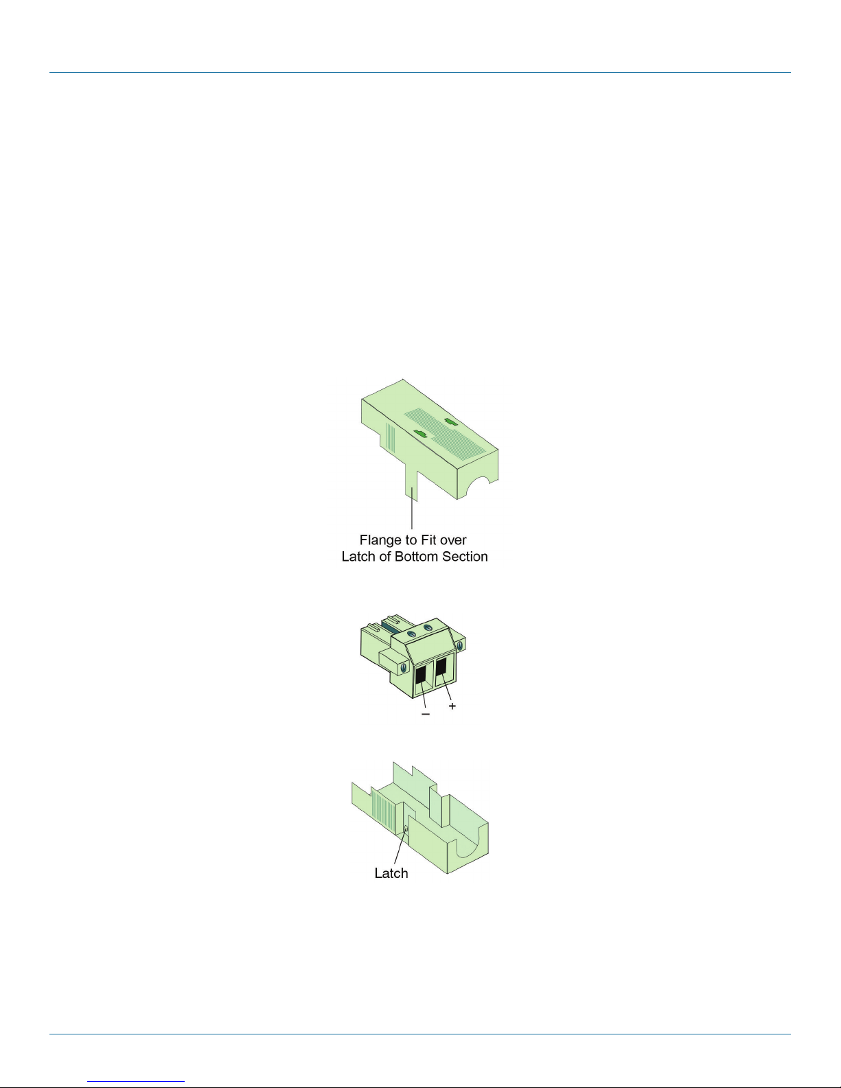
If you received a chassis that uses DC input power (part numbers WRT4001A-DC–WRT4004A-DC), the package includes a
standard DC power connection set (Figure 3-30, Figure 3-31, and Figure 3-32).
Figure 3-30. Top Section of Connector Shell.
Figure 3-31. DC Power Connector.
Figure 3-32. Bottom Section of Connector Shell.
To connect your WRT4000 Series Router to a DC power source, perform the following procedure. Use the steps to connect cables
to user equipment and to prepare the chassis for configuration and use.
NOTE: Consult Section 2.4, Hardware Description, to see diagrams of the chassis and the ports.
1. Place the WRT4000 Series Router chassis at its physical location in the network—for example, on a shelf or tabletop.
724-746-5500 | blackbox.com
Page 27
Page 28
Chapter 3: Installation
NOTE: Do not place anything below or on top of the chassis; it must have proper ventilation for cooling.
2. Connect the WRT4000 Series Router chassis’s ports to their network devices. For example, connect the LAN ports, WAN port,
USB port, and expansion ports (serial port, etc.) to the network devices, as follows:
a. Use an Ethernet 10BASE-T cable to connect the WAN port to the WAN equipment.
b. Use an Ethernet 10BASE-T cable to connect each LAN port to its equipment.
c. Connect additional network equipment to the remaining ports on the WRT4000 Series Router chassis. This includes any port in
the expansion slot.
3. Use an Ethernet cable to connect your management console (for example, a PC) to a LAN port (eth 1) on the back of the
WRT4000 Series Router.
4. If the WRT4000 Series Router chassis will use only AC input power, go to step 10.
5. If the WRT4000 Series Router chassis will use DC input power, follow step 6 through step 9 to prepare the chassis for its DC
power connection.
NOTE: The DC power source must supply 24 VDC.
6. Make sure the WRT4000 Series Router chassis is disconnected from all power sources.
7. Do the following:
a. Turn the DC power connector (the DC power plug) on its side, with the screwheads at the left and with the prongs pointing
away from you (as shown in Figure 3-33).
Figure 3-33. DC Power Connector, on Side.
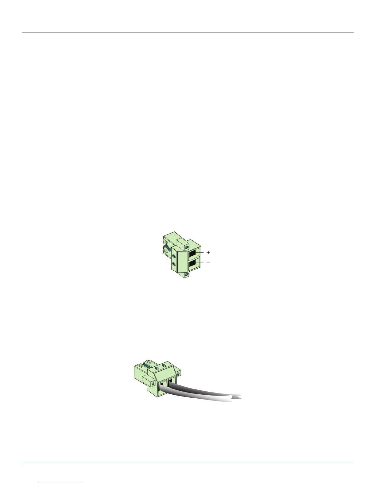
b. Note the following:
• The top post is + (for the positive wire).
• The bottom post is − (for the negative/return wire).
c. Connect a minimum 14 AWG two-wire input cable to the green two-pin power connector (that is, the power plug). Make sure
you connect the correct wire to each positive or negative post. Figure 3-34 shows the plug with the cables attached.
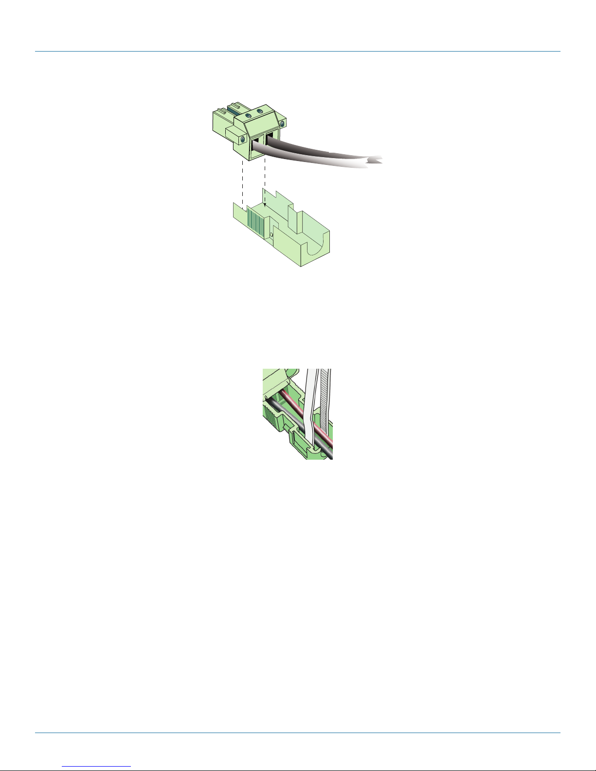
8. A shell cover is provided with the DC power connector, to provide strain relief for the wires. Restrain the wires against the
lower half of the shell, and place the shell around the connector, as described in the following substeps:
a. Seat the DC power connector (the plug) into the bottom half of the shell. The connector will seat into the shell in only one
way, as shown in Figure 3-35.
Page 28
Figure 3-34. DC Power Connector with Wires.
724-746-5500 | blackbox.com
Page 29
Chapter 3: Installation
Figure 3-35. Cabled DC Power Connector and Bottom Section of Shell.
NOTE: The top and bottom sections of the shell differ. The top section (recall Figure 3-30) has flanges to fit against the bottom
section’s latches (recall Figure 3-31).
b. Insert the end of a cable-tie through one of the holes in the bottom of the connector shell (Figure 3-36).
NOTE: The cable lock (the hollow block) can be above the lower shell (as shown) or below the lower shell.
Figure 3-36. Cable-Tie through Bottom of DC Power Connector Shell.
c. Pull the cable-tie across the cables and through the other hole in the shell bottom.
d. Put the end of the cable-tie through its lock and pull the cable-tie snug around the cables.
NOTE: The lock is designed so that the cable may move in only one direction. If you need to remove the cable, you will have to
cut the cable.
e. If you wish, you may trim the end of the cable-tie to be flush with the lock.
CAUTION: If you trim the cable-tie, trim it flush with the lock. Do not leave a few millimeters of the cable-tie extending past the
lock. It is better to leave the cable-tie untrimmed than to cut it non-flush.
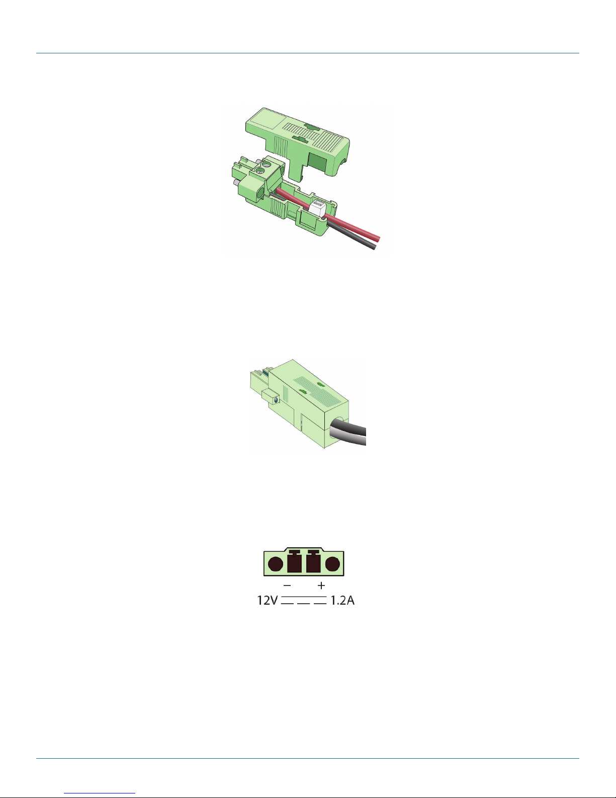
f. With the plug seated into the bottom section, place the top section of the shell onto the bottom section. Do not yet snap them
into place. Figure 3-37 shows how the top and bottom sections fit together around the DC power plug.
724-746-5500 | blackbox.com
Page 29
Page 30
Chapter 3: Installation
Figure 3-37. Top Section of Shell above Cabled DC Power Connector in Bottom Section of Shell.
g. Make sure the DC power connector sits properly in the bottom section. Then snap the top and bottom sections together, as
shown in Figure 3-38.
NOTE: Make sure the cables do not get caught between edges of the shell. The cables should fit through the cable hole without
catching on an edge.
Figure 3-38. Closed Shell Assembly.
h. If you need to take the case apart, grasp each flange of the top section and gently pull them away from the latches on the
bottom section. Then pull the top section off the bottom section. Repeat step 8a through step 8g to reassemble the connector
case.
NOTE: Figure 3-39 shows the standard orientation of the WRT4000 Series Router’s DC power input port.
Figure 3-39. WRT4000 Series Router DC Power Input Port.
Flanges on the plug (Figure 3-40) allow it to fit into the DC power input port on the backplate of the WRT4000 Series Router
chassis in only one way. You may need to turn the plug over to fit it into the port.
Page 30
724-746-5500 | blackbox.com
Page 31

Chapter 3: Installation
Figure 3-40. DC Shell Assembly Connector Flanges.
9. Do the following:
a. If necessary, rotate the plug’s shell assembly 180° around the axis corresponding to the DC power cable (Figure 3-41 and
Figure 3-42).
Figure 3-41. Rotate DC Shell Assembly 180 Degrees around Axis of Power Cable.
Figure 3-42. DC Shell Assembly Rotated 180 Degrees.
b. Plug the DC power connector into the DC power input port on the rear of the WRT4000 Series Router chassis.
c. Then connect the other end of the DC power cable to a -48 volt DC power source.
NOTE: The power source must supply 24 VDC.
CAUTION: The DC power source must match the DC input power rating indicated on the WRT4000 Series Router chassis.
• The WRT4000 Series Router chassis powers up.
10. If the WRT4000 Series Router chassis will use AC input power (in addition to DC power or instead of DC power), connect the
AC power supply to the chassis, and then connect the AC power supply to a power outlet supplying 100–240 VAC at 47–63
Hz.
• If the chassis is already connected to DC power, the chassis has already powered up. If the chassis uses only AC power, the
chassis powers up now.
• The WRT4000 Series Router chassis’s hardware installation is complete.
724-746-5500 | blackbox.com
Page 31
Page 32

Chapter 3: Installation
3.7 The Next Step
To log into the WRT4000 Series Router and configure it for your network, see the procedures in Chapter 4.
NOTE: If you installed a new SIM, GSM or LTE card, use the initialization stream provided by the GSM or LTE carrier to activate the
SIM in the carrier network. This activation can be set up in the WRT4000 Series Router’s custom command list. (Select
System, then select Custom Commands. Add the carrier’s activation commands to the list and save the commands. Each
carrier has a unique set of commands.)
Page 32
724-746-5500 | blackbox.com
Page 33

Chapter 4: Configuration—General Settings
4. Configuration—General Settings
The WRT4000 Series Cellular Wireless Router provides wireless and cabled connections to a local area network (LAN) and to
peripheral devices and remote devices.
Follow the procedures in this discussion to configure the WRT4000 Series Cellular Wireless Router:
• Using the WRT4000 Series Cellular Wireless Router’s Management System
• Navigating the WRT4000 Series Cellular Wireless Router’s Management System
• Basic Configuration
• Configuration for the Network
4.1 Using the WRT4000 Series Cellular Wireless Router’s Management System
See the following discussions:
• Connecting to the WRT4000 Series Cellular Wireless Router
• Logging In
• Ending the Session
4.1.1 Connecting to the WRT4000 Series Cellular Wireless Router
Because the WRT4000 Series Cellular Wireless Router’s management system can display in a browser window, the management
terminal can run on any platform (for example, a Windows, Mac, or Linux platform) that supports a Web browser.
To use the WRT4000 Series Cellular Wireless Router management system, connect the management terminal to one of the
Ethernet LAN ports on the WRT4000 Series Cellular Wireless Router’s rear panel (Figure 4-1).
1. We recommend using the Web interface to manage the WRT4000 Series Cellular Wireless Router. However, you can also use a
command line interface (CLI) to manage the router.
CAUTION: Do not connect the management terminal to the WRT4000 Series Cellular Wireless Router’s Ethernet WAN port.
The LAN ports on the WRT4000 Series Cellular Wireless Router’s rear panel are on a single private network. The router’s software
includes a DHCP server that assigns IP addresses to devices connected to those LAN ports. Devices connected to those LAN ports
see the gateway address 192.168.1.1 representing the router.
NOTE: The WRT4000 Series Cellular Wireless Router’s WAN port (also on the rear panel) is on a separate network from its LAN
ports. The router’s WAN port is a DHCP client, by default.
Ethernet L AN ports (eth 1)
Ethernet
WAN port
(eth 0)
4.1.2 Logging In
1. Make sure you have a terminal available to manage the WRT4000 Series Cellular Wireless Router, and make sure the terminal’s
power is on.
2. Connect the router to an AC power adaptor or a DC power source.
• The WRT4000 Series Cellular Wireless Router powers on.
Figure 4-1. WRT4000 Series Router rear panel.
724-746-5500 | blackbox.com
Page 33
Page 34
Chapter 4: Configuration—General Settings
3. Use an Ethernet cable to connect your management terminal to an Ethernet LAN port on the WRT4000 Series Cellular Wireless
Router’s rear panel.
CAUTION: Do not connect the management terminal to the WRT4000 Series Router's WAN port (labeled eth0).
• The LAN port assigns an IP address to your management terminal.
4. On the management terminal, open a Web browser.
NOTE: The example used in this procedure (connection to an Ethernet LAN port on the rear panel of the WRT4000 Series Router
chassis) is the most direct connection for managing the WRT4000 router’s operating system.
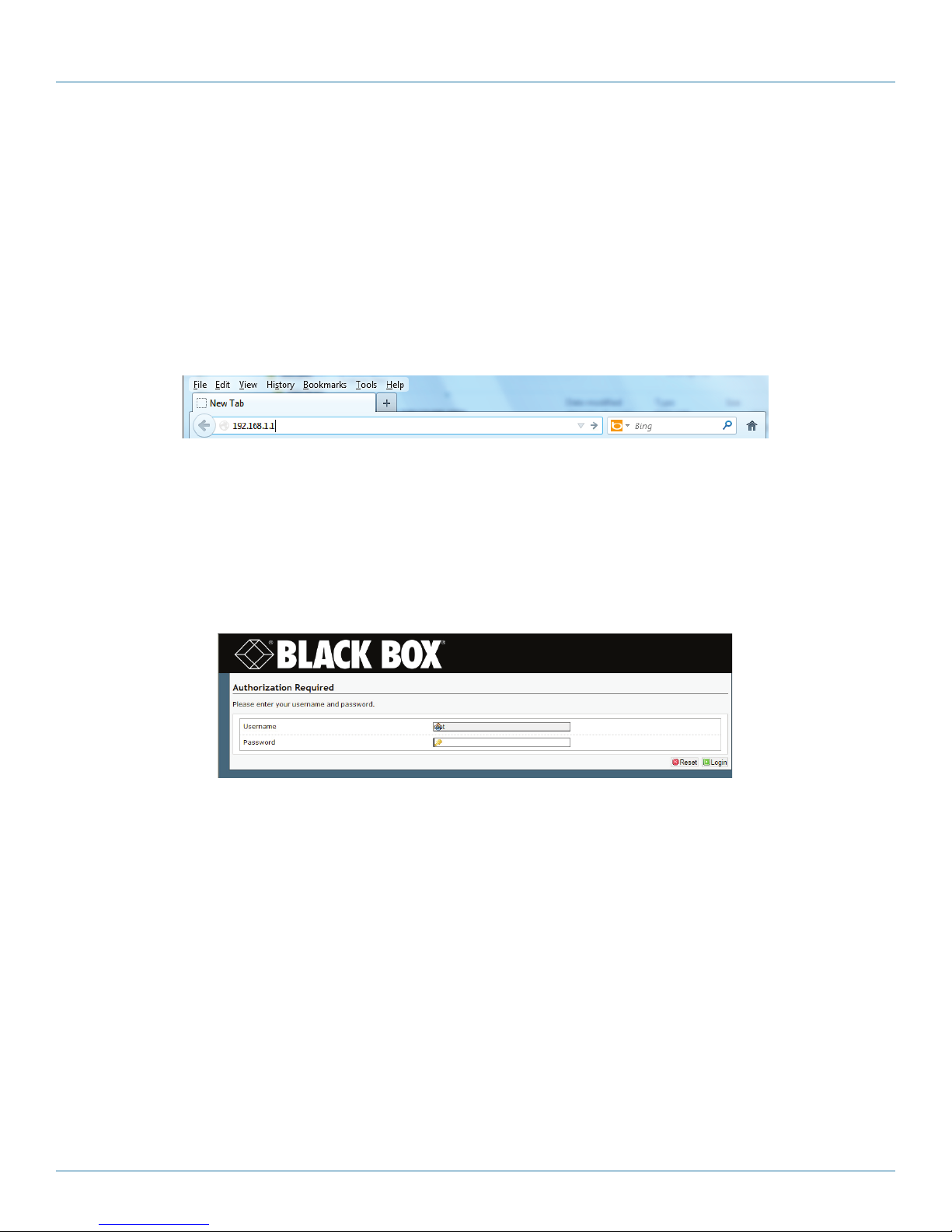
5. In the browser's address field, type the WRT4000 Series Cellular Wireless Router’s gateway IP address 192.168.1.1 (or, if you
prefer, type http://192.168.1.1), and press the console’s Enter key (Figure 4-2).
Figure 4-2. Browser Address Field.
NOTE: If the browser asks whether the WRT4000 Series Cellular Wireless Router (192.168.1.1) may set cookies, answer Yes, or Yes
for the Session, or something similar.
CAUTION: Do not block cookies for the WRT4000 Series Cellular Wireless Router. Otherwise, you might not be able to manage
the router.
• The browser navigates to the specified IP address and displays the WRT4000 Series Cellular Wireless Router Log-In Screen
(Figure 4-3).
Figure 4-3. WRT4000 Series Cellular Wireless Router Log-In Screen.
NOTE: The Username field might display the user name. (Figure 4-3 shows the default user name root.)
CAUTION: A message to enable JavaScript (Figure 4-4) might also display in your browser.
Javascript required!
You must enable JavaScript in your browser or the management system will not work properly.
Figure 4-4. Message to Enable JavaScript.
The WRT4000 Series Cellular Wireless Router management system uses JavaScript in its browser-based display. If you see the
message in Figure 4-4, do the following:
• On the browser menu, open Tools or Options (or an equivalent menu item in your browser).
• In the browser’s menu system, Enable JavaScript, and Save that setting.
• Right-click on the browser screen, and select Refresh, Rewrite, or Reload (or the equivalent for your browser).
• The WRT4000 Series Cellular Wireless Router Log-In Screen is redisplayed, without a message to enable JavaScript.
Page 34
724-746-5500 | blackbox.com
Page 35

Chapter 4: Configuration—General Settings
6. Type your user name and password in the appropriate fields of the WRT4000 Series Cellular Wireless Router Log-In Screen.
(Recall Default Log-In Values, on page X.) Then press the console’s Enter key or select the screen’s Login button (to the lower
right of the router log-In Fields).
• The default user name is root.
• The default password is blackbox!1.
NOTE: Ask your network administrator for your assigned user name and password.
• The system accepts your log-in. Then the WRT4000 Series Cellular Wireless Router Status Overview Screen is displayed (Figure
4-5). This screen provides an overview of the router’s status.
NOTE: If the WRT4000 Series Cellular Wireless Router’s WAN port is connected to a network, you may see the WAN port’s
assigned IP address (because the router’s WAN port is by default a DHCP client).
NOTE: In Figure 4-5, the IP address assigned to the router’s WAN port is 192.168.101.109.
Figure 4-5. WRT4000 Series Cellular Wireless Router Status Overview Screen.
On the WRT4000 Series Cellular Wireless Router management screens, the top row of tabs indicates the management areas.
• Status
• System
• Network
• Statistics
• Logout
There is a second row of tabs under each management area. The second row provides detail for the selected management area.
In Figure 4-5, the Status management area shows the following detail tabs:
• Overview
724-746-5500 | blackbox.com
Page 35
Page 36

Chapter 4: Configuration—General Settings
• Firewall
• Routes
• System Log
• Kernel Log
• Processes
•Realtime Graphs
An Auto Refresh button (to the right of the Black Box logo) is displayed on several screens. You can select this button to turn
automatic screen refreshment on or off.
7. To manage your WRT4000 Series Cellular Wireless Router, do the following:
a. To set values for the router’s IP address and other parameters, see Section 4.2, Navigating the WR4000 Router’s Management
System.
b. To review the WRT4000 Series Cellular Wireless Router’s settings and performance, see Chapter 6, Monitoring the WRT4000
Series Cellular Wireless Router.
4.1.3 Managing the Browser Display
Sometimes a browser lets part of a display bleed off the screen (as in Figure 4-6).
Figure 4-6. Browser screen bleeding (Configure Custom Commands screen).
In that case, hold down the Control key (sometimes marked Ctrl) and press the Minus key (-, also called the Hyphen key) until all
the information displays within the browser (Figure 4-7).
Figure 4-7. Browser screen without bleeding (Configure Custom Commands screen.
Page 36
724-746-5500 | blackbox.com
Page 37

Chapter 4: Configuration—General Settings
4.2 Navigating the WRT4000 Series Cellular Wireless Router’s Management System
4.2.1 Saving or Discarding Changes
Buttons to Reset, Save, or Save & Apply are displayed in the lower right-hand corner of the WRT4000 Series Cellular Wireless
Router configuration screens. You can use them as described below:
• Select the Save button to save changes that will take effect after the router is rebooted.
• Select the Save & Apply button to save changes that take effect immediately.
• Select the Reset button to discard changes you have made but have not yet saved, and to see the screen with its values before
you made those changes.
NOTE: The browser will display a message in the upper right corner of its screen when you have not saved the configuration
(Figure 4-8).
NOTE: The browser will also display a message if you use the WRT4000 Series Cellular Wireless Router screens to reboot the
chassis before you have saved the configuration (Figure 4-9).
Figure 4-9. Message to Save Configuration before Rebooting.
Figure 4-8. Message about Unsaved Changes.
724-746-5500 | blackbox.com
Page 37
Page 38

Chapter 4: Configuration—General Settings
CAUTION: The WRT4000 Series Cellular Wireless Router operating system will not report unsaved changes in the configuration if
you use processes that are not under the control of the router management system’s screens—for example, when you
close the browser or when you manually reboot the chassis. If you wish to save changes, make sure you select the
Save button or the Save & Apply button before you close the browser window or manually reboot the chassis, or use
the screens to reboot.
NOTE: If you close the browser without saving changes in the configuration, the previous configuration is used when you reopen
the WRT4000 Series Router Management System in the browser.
NOTE: The most recently saved configuration will be used only after the WRT4000 Series Cellular Wireless Router chassis has been
restarted (rebooted). For that reason, the message “Unsaved Changes” will persist in the upper right corner of the router
operating system screens until the router chassis has been restarted.
4.2.2 Restarting (Rebooting) the WRT4000 Series Cellular Wireless Router
There may be times when the WRT4000 Series Cellular Wireless Router needs to be restarted. We recommend using the menu
system to restart the router, because that provides a controlled approach to restarting. Any processes that are running will be shut
down properly before the router restarts.
CAUTION: You can manually restart the WRT4000 Series Cellular Wireless Router by disconnecting it from its power source and
then reconnecting it to power. But that method of rebooting might interrupt processes running on the router.
1. To restart the WRT4000 Series Cellular Wireless Router, select the System management area.
2. Then select the Reboot tab.
• The System Reboot screen is displayed (Figure 4-10).
Figure 4-10. WRT4000 Series Cellular Wireless Router System Reboot.
3. On this screen, select Perform Reboot.
• The menu system restarts the router. During the reboot, the message in Figure 4-11 is displayed.
Wai ting fo r 192.16 8.1.1…
or
Please wait. Device rebooting.
4. After a few seconds, select the tab for the Status management area.
• The WRT4000 Series Cellular Wireless Router Log-In Screen is displayed (Figure 4-12).
Page 38
Figure 4-11. Message while rebooting.
724-746-5500 | blackbox.com
Page 39

Chapter 4: Configuration—General Settings
Figure 4-12. Router login screen.
4.2.3 Ending the Session
1. When you wish to log out, select the Logout tab.
• The system logs out, and the WRT4000 Series Cellular Wireless Router Log-In Screen is redisplayed (recall Figure 4-12).
4.3 Basic Configuration
Basic configuration includes assigning the WRT4000 Series Cellular Wireless Router its IP address, device name, and similar items.
You might also want to look at the following:
• Revising Lists in the WRT4000 Series Cellular Wireless Router’s Management System
• Configuring the Management System Language
• Configuring the Device Name and Time of Day
• Synchronizing the WRT4000 Series Cellular Wireless Router’s Time of Day
• Configuring System Logging
• Overriding the MAC Information
4.3.1 Revising Lists in the WRT4000 Series Cellular Wireless Router’s Management System
For lists in the WR4000 Series Router’s Management System:
• To add an item to a list, click on [+] (the line-item Add button).
• To delete an item from a list, highlight the item and press the Delete key on your keyboard.
NOTE: Some items can be deleted by clicking on [x] (the line-item Delete button).
• When you have finished modifying items, click the Save & Apply button on the screen.
4.3.2 Configuring the Management System Language
1. To set the language used for the WRT4000 Series Cellular Wireless Router management system, do the following:
a. Select the System management area.
b. Select the System configuration area.
c. Then select the Language and Style detail tab.
• The Screen to Set the Management System Language is displayed (Figure 4-13).
724-746-5500 | blackbox.com
Page 39
Page 40

Chapter 4: Configuration—General Settings
Figure 4-13. Screen to Set the Operating System Language.
2. On the Screen to Set the Operating System Language, select the Language pulldown menu and select your preferred language.
NOTE: Currently, the management system interface is available only in English.
To set time-of-day synchronization, see Synchronizing the WRT4000 Series Cellular Wireless Router’s Time of Day.
4.3.3 Configuring the Device Name and Time of Day
1. To configure the WRT4000 Series Cellular Wireless Router’s identity within the network, and to configure time zone and time-
of-day synchronization source for the WRT4000 Series Cellular Wireless Router, do the following:
a. Select the System management area.
b. Then select the System configuration area.
c. If necessary, select the General Settings detail tab.
• The System Screen for General Settings is displayed (Figure 4-14).
On the System Screen for General Settings, you can set a unique name for this WRT4000 Series Cellular Wireless Router. You can
also set its local time, and you can set a hierarchy of network time protocol (NTP) servers for synchronizing the WRT4000 Series
Cellular Wireless Router’s time of day.
Page 40
724-746-5500 | blackbox.com
Page 41

Chapter 4: Configuration—General Settings
Figure 4-14. System Screen for General Settings.
2. In the Hostname field, type the WRT4000 Series Cellular Wireless Router’s name. Then click the Save & Apply button (in the
lower right corner of the screen).
• The WRT4000 Series Cellular Wireless Router saves its new name and uses the new name immediately.
NOTE: The name must be unique within the network. Get all names and IP addresses from your network administrator.
CAUTION: If you type a non-permitted character, the entire name displays in red. If you try to save a name with non-permitted
characters, Figure 4-15 is displayed.
Figure 4-15. Message about Invalid Entry.
In that case, click the OK button to close the message. Examine the name and remove special characters until the name display
returns to black. Then save the name again.
Some quick guidelines for device names follow:
• Spaces are not permitted in a device name.
• The name cannot end with a hyphen (-), a period (.), or an underscore (_).
• Most other special characters are not permitted anywhere in the name.
724-746-5500 | blackbox.com
Page 41
Page 42
Chapter 4: Configuration—General Settings
3. To use the browser’s date and time settings, click the button to Sync with browser.
• The WRT4000 Series Cellular Wireless Router operating system adopts the browser’s time-of-day settings.
4. Select the arrow on the right of the Timezone field to pull down a list of major cities in each time zone. In the pulldown menu,
select the time zone the WRT4000 Series Cellular Wireless Router will use (usually the closest city in your time zone). Then
select the Save & Apply button.
• The WRT4000 Series Cellular Wireless Router’s operating system displays the selected city’s time.
NOTE: To get the time of day for the WRT4000 Series Cellular Wireless Router at regular intervals, see Section 4.3.4,
Synchronizing the WRT4000 Series Cellular Wireless Router’s Time of Day.
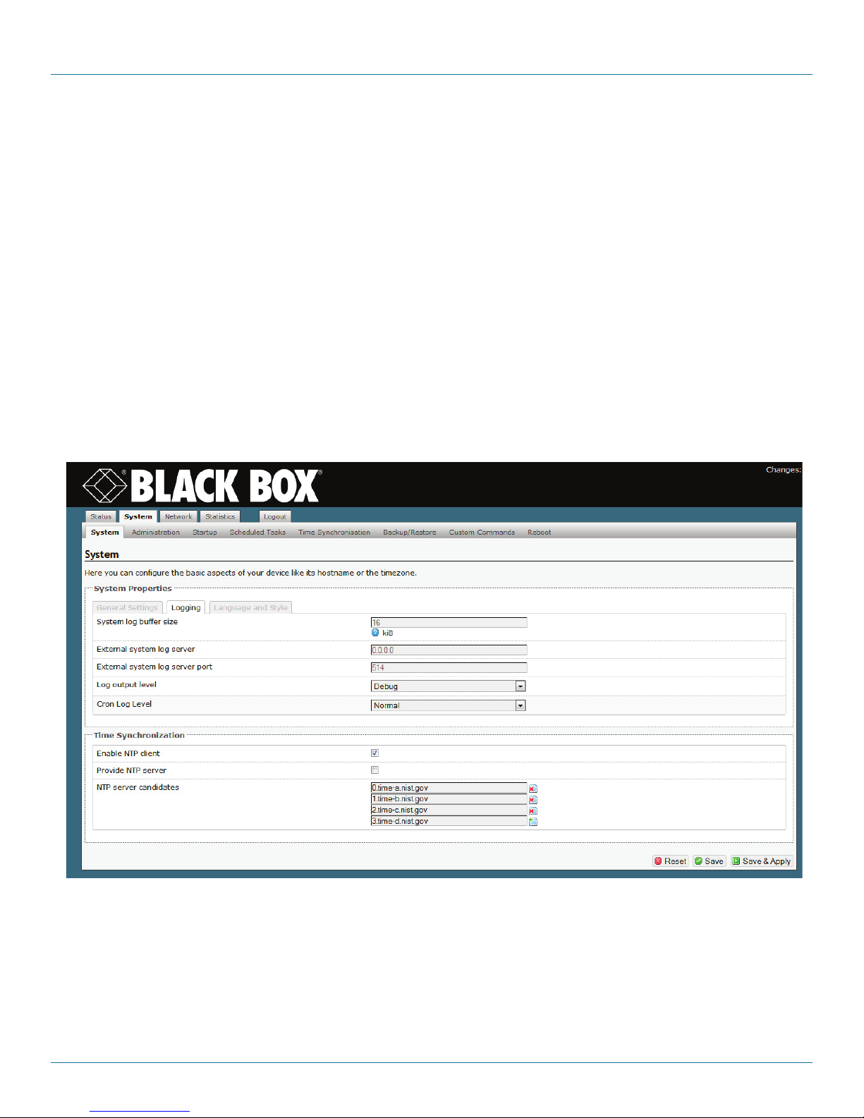
4.3.4 Configuring System Logging
1. To set logging of system activities for the WRT4000 Series Cellular Wireless Router, do the following:
a. Select the System management area.
b. Select the System configuration area.
c. Then select the Logging detail tab.
• The Screen to Set System Logging is displayed (Figure 4-16).
2. On the Screen to Set System Logging, enter information into the following fields:
NOTE: Consult your network administrator to set values for these parameters.
• System Log Buffer Size (kilobytes)
• External System Log Server (IP address)
• External System Log Server Port (port number)
• Log Output Level (select from pulldown menu):
Page 42
Figure 4-16. Screen to Set System Logging.
724-746-5500 | blackbox.com
Page 43

- Debug
- Info
- Notice
- Warning
- Error
- Critical
- Alert
- Emergency
• Cron Log Level (select from pulldown menu):
4
“Cron” is an abbreviation for “chronological.”
- Debug
- Normal
- Warning
Chapter 4: Configuration—General Settings
4
NOTE: To set time-of-day synchronization, see Section 4.3.5, Synchronizing the WRT4000 Series Cellular Wireless Router’s Time of
Day.
4.3.5 Synchronizing the WRT4000 Series Cellular Wireless Router’s Time of Day
Do both of the following, in the order listed here:
• Configure the time-of-day options by Configuring Time-of-Day Synchronization as described in Section 4.3.5.1.
• Select one of the configured options by Selecting Time-of-Day Synchronization as described in Section 4.3.5.2.
4.3.5.1 Configuring Time-of-Day Synchronization
1. Select the System management area.
2. Select the Time Synchronization detail tab.
• The Time Synchronization Screen is displayed (Figure 4-17).
724-746-5500 | blackbox.com
Page 43
Page 44

Chapter 4: Configuration—General Settings
Figure 4-17. Time Synchronization Screen.
NOTE: The value for Current System Time, displayed on this screen, is configured in Section 4.3.3, Configuring the Device Name
and Time of Day.
3. Under General, in the Update Interval field, enter the number of seconds between time-of-day synchronization requests.
4. Under General, enter the value for the Count of Time Measurements.
5. Under Clock Adjustment, enter the value for the Offset Frequency.
6. Under Time Servers, do the following:
a. For each NTP server that the WRT4000 Series Cellular Wireless Router might follow to synchronize time of day, do the
following:
- Under Hostname, type a name for an NTP server.
NOTE: This entry can be an IP address or a website URL.
- Under Port, type the port number the WRT4000 Series Cellular Wireless Router will use to reach the NTP server.
b. If you need to add an NTP server, click on the Add button.
• A row is displayed for another NTP server.
c. If you wish to delete an NTP server entry, click on the Delete button for that row.
• The NTP server entry is deleted.
7. When you have finished configuring the fields on this screen, do one of the following:
a. Select Save if you want the settings to take effect after the WRT4000 Series Cellular Wireless Router reboots.
b. Select Save & Apply if you want the settings to take effect immediately.
Page 44
724-746-5500 | blackbox.com
Page 45

Chapter 4: Configuration—General Settings
c. Select Reset if you want to discard the screen’s configuration and use the previous settings.
8. Continue to Section 4.3.5.2, Selecting Time-of-Day Synchronization.
4.3.5.2 Selecting Time-of-Day Synchronization
NOTE: To use this procedure, NTP servers must already be configured. Follow the procedure in Section 4.3.5.1, Configuring Time-
of-Day Synchronization.
9. Do the following to navigate to any of the screens for system management.
a. Select the System management area.
b. Then select the System configuration area.
• The System Screen for General Settings is displayed (Figure 4-18).
Figure 4-18. System Screen, Time Synchronization Settings.
NOTE: Time-of-day Time Synchronization parameters are listed in the lower half of the screen (Figure 4-19). These parameters are
listed regardless of the heading (General Settings, Logging, or Language and Style) in the upper portion of the System
screen.
Figure 4-19. System screen, Time Synchronization Settings.
724-746-5500 | blackbox.com
\
Page 45
Page 46
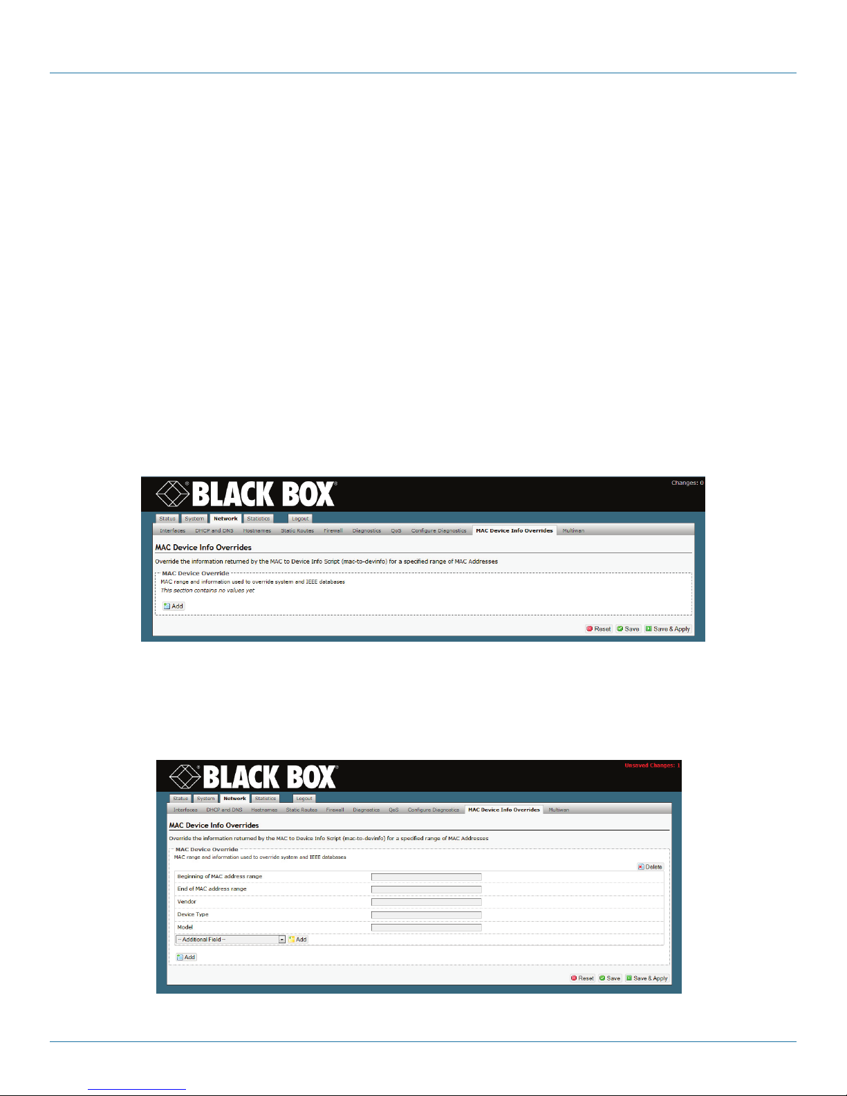
Chapter 4: Configuration—General Settings
10. Consult your network administrator to determine whether the WRT4000 Series Cellular Wireless Router will receive time-of-
day synchronization (substep b) or will provide that synchronization (substep a).
a. If the WRT4000 Series Cellular Wireless Router will provide the time of day, select the box to Provide NTP Server.
b. In most cases, the WRT4000 Series Cellular Wireless Router will receive the time of day. In those cases:
• Select the box to Enable NTP Client.
• Then type the name of the first NTP server the router will look for.
• In boxes below the principal NTP server field, type names of additional NTP servers, in the order the router will use.
• Select the box to the right of each field for an NTP server to activate or inactivate that NTP server.
11. When you have selected your preferences for the parameters in this procedure, select the Save & Apply button.
• The changes are saved and are used immediately.
4.3.6 Overriding the MAC Information
You can override some MAC information.
1. Select Network, MAC Device Info Overrides.
• The WRT4000 Series Cellular Wireless Router MAC Device Overrides, Initial Screen is displayed (Figure 4-20).
Figure 4-20. WRT4000 Series Cellular Wireless Router MAC Device Overrides, Initial Screen.
2. Click on the Add button.
• Fields are opened for a MAC device, as shown in the WRT4000 Series Cellular Wireless Router MAC Device Overrides, Entry
Screen (Figure 4-21).
Figure 4-21. WRT4000 Series Router MAC device overrides, entry screen.
Page 46
724-746-5500 | blackbox.com
Page 47

Chapter 4: Configuration—General Settings
3. Enter values in the fields shown to override MAC information sent by the router.
4. Then do one of the following:
a. If you wish to configure overrides for another MAC device, return to step 2.
b. If you have finished configuring host devices, do one of the following:
• If you wish to save the configuration, but not to use it until the router is restarted, select Save.
• If you wish to save the configuration and use it immediately, select Save and Apply.
• If you wish to discard the configuration, select Reset.
4.4 Configuration for the Network
4.4.1 DHCP and DNS
You can configure the WRT4000 Series Cellular Wireless Router's use of Dynamic Host Configuration Protocol (DHCP) and the
Domain Name System (DNS). Confer with your network administrator to determine values for fields in these configuration
screens.
1. On any WRT4000 Series Cellular Wireless Router operating system screen, select the Network tab. Then select the DHCP and
DNS tab. (And, if necessary, select the General Settings tab.)
• The browser displays the DHCP and DNS General Settings Screen (Figure 4-22) for configuration.
2. When you have finished configuring the fields on this screen, select the Save button.
3. Then select the tab for Resolve and Hosts Files
• The DHCP and DNS Resolve and Hosts Files Screen is displayed (Figure 4-23) for configuration.
Figure 4-22. DHCP general settings screen.
724-746-5500 | blackbox.com
Page 47
Page 48

Chapter 4: Configuration—General Settings
Figure 4-23. DHCP and DNS resolve and hosts files screen.
4. Whne you have finished configuring the fields on the screen, select the Save button.
5. Then select the tab for TFTP Settings.
• The DHCP and DNSTFTP Settings Screen is displayed (Figure 4-24) for configuration.
Figure 4-24. DHCP and DNS TFTP settings screen.
6. When you have finished configuring the fields on this screen, select the Save button.
7. Then select the tab for Advanced Settings.
• The DHCP Advanced Settings Screen is displayed (Figure 4-25) for configuration.
Page 48
724-746-5500 | blackbox.com
Page 49

Chapter 4: Configuration—General Settings
Figure 4-25. DHCP advanced settings screen.
8. When you have finished configuring the fields on this screen, do one of the following:
a. If you wish to save the configuration and use it immediately, select Save and Apply.
b. If you wish to save the configuration, but not use it until the WRT4000 Series Router is restarted, select Save.
c. If you wish to discard the configuration, select Reset.
4.4.2 Network Hosts
1. To configure names for host devices (in the private network and in the public network), select Network, Hostnames.
• The WRT4000 Series Cellular Wireless Router Network Host Names Screen is displayed (Figure 4-26).
Figure 4-26. WRT4000 Series Cellular Wireless Router Network Host Names Screen.
2. To add a host name, click on the Add button.
• An entry row is added to the screen, as shown in the Network Host Names Add screen (Figure 4-27).
724-746-5500 | blackbox.com
Page 49
Page 50

Chapter 4: Configuration—General Settings
Figure 4-27. Router network hosts names add screen.
3. In the Hostname field, type a name for the host device.
4. In the IP Address field, type the host device’s IP address.
5. Then do one of the following:
a. If you want to add another host device to the list, return to step 2.
b. If you have finished configuring host devices, do one of the following:
• If you wish to save the configuration, but not to use it until the router is restarted, select Save.
• If you wish to save the configuration and use it immediately, select Save and Apply.
• If you wish to discard the configuration, select Reset.
4.4.3 Routing
Configure the routing screens with settings determined by your network administrator.
1. To create a static routing table, select Network, Static Routes.
• The Static Routes Configuration screen is displayed (Figure 4-28).
Figure 4-28. WRT4000 Series Cellular Wireless Router Static Routes Configuration Screen.
2. Select the Add button under the Interface headings for IPv4 or for IPv6, as appropriate for your network. (The example uses IP
version 4.)
Page 50
724-746-5500 | blackbox.com
Page 51

Chapter 4: Configuration—General Settings
• The WRT4000 Series Cellular Wireless Router Static Routes Table is displayed (Figure 4-29).
Figure 4-29. WRT4000 Series Cellular Wireless Router Static Routes Table.
3. When you have finished configuring this screen, select the Save & Apply button.
• The Static Routes Configuration screen is redisplayed (Figure 4-28).
4. On that screen, do one of the following:
a. If you wish to save the configuration and use it immediately, select Save and Apply.
b. If you wish to save the configuration, but not to use it until the Router is restarted, select Save.
c. If you wish to discard the configuration, select Reset.
4.4.4 Firewall Configuration
Get all firewall settings from your network administrator.
1. Select the Network tab. Then select the Firewall tab. If necessary, select the General Settings tab.
• The Firewall Settings screen is displayed (Figure 4-30).
Figure 4-30. Firewall General Settings screen.
724-746-5500 | blackbox.com
Page 51
Page 52

Chapter 4: Configuration—General Settings
2. After configuring the fields on the screen, select the Save & Apply button. Then select the Add button.
• The Firewall General Settings screen to Add Record is displayed.
Figure 4-31. WRT4000 Series Cellular Wireless Router Firewall General Settings, Add Record.
3. After configuring the fields on the screen, select the Save & Apply button. Then select the tab for Port Forwards.
• The Firewall Port Forwards screen is displayed (Figure 4-32).
Figure 4-32. Firewall Port Forwards screen.
4. After configuring the fields on the screen, select the Save & Apply button. Then select the tab for Traffic Rules.
• The Firewall Traffic Rules screen is displayed (Figure 4-33).
Page 52
724-746-5500 | blackbox.com
Page 53

Chapter 4: Configuration—General Settings
Figure 4-33. Firewall Traffic Rules screen.
5. After configuring the fields on this screen, select the Save & Apply button. Then select the tab for Custom Rules.
• The Firewall Custom Rules screen is displayed (Figure 4-34).
6. After listing custom rules for the firewall, do one of the following:
a. If you wish to save the configuration and use it immediately, select Save and Apply.
b. If you wish to save the configuration, but not to use it until the Router is restarted, select Save.
c. If you wish to discard the configuration, select Reset.
Figure 4-34. Firewall Custom Rules.
724-746-5500 | blackbox.com
Page 53
Page 54

Chapter 4: Configuration—General Settings
4.4.5 Configuring Traffic Priority
Use the fields in Figure 4-35 to configure Quality of Service (QoS) settings for network traffic. Consult your network administrator
for the settings to use.
Figure 4-35. Quality of Service Configuration Screen.
After configuring the fields on the screen, do one of the following:
a. If you wish to save the configuration and use it immediately, select Save and Apply.
b. If you wish to save the configuration, but not to use it until the Router is restarted, select Save.
c. If you wish to discard the configuration, select Reset.
Page 54
724-746-5500 | blackbox.com
Page 55

Chapter 5: Configuring the Serial Ports
5. Configuring the Serial Ports
5.1 Connecting to the WRT4000 Series Cellular Wireless Router
Connect a management terminal to the WRT4000 Series Cellular Wireless Router, and log into the management system. (For
details, see Using the WRT4000 Series Cellular Wireless Router’s Management System, in the document Configuring the
WRT4000 Series Cellular Wireless Router.)
5.2 Configuring a Serial Port
1. On the WRT4000 Series Cellular Wireless Router Management System, select the Network tab.
• The Network Interfaces Screen is displayed (Figure 5-1).
Figure 5-1. Network Interfaces Screen.
2. Then select the Serial tab.
• The Serial Port Configuration Screen is displayed (Figure 5-2).
Figure 5-2. Serial Port Configuration Screen.
The default configuration for the dual serial-port module includes the following. (Port names—for example, ttyACM10—may
differ in your set-up.)
• ttyACM10: The Asynchronous Encapsulation protocol is the default configuration for one of the physical serial ports. This protocol sends and receives Async Encaps transmissions to and from a remote device.
724-746-5500 | blackbox.com
Page 55
Page 56

Chapter 5: Configuring the Serial Ports
• ttyGRE5: This virtual port uses general route encapsulation (GRE) to send and receive Frame Relay transmissions. (GRE uses the
Internet Protocol, IP.)
• ttyACM11: The Telnet Terminal protocol is the default configuration on one of the physical serial ports.
The port configurations named ttyACM10 and ttyACM11 refer to discrete serial ports; each serves only one physical port. The
port configuration named ttyGRE5 is a virtual port and can serve both physical serial ports. Additional virtual ports can be
configured.
3. If you wish to customize a port configuration, select that row’s Edit button.
For example, select the edit button in the row for ttyACM10.
• The Serial Port Configuration Detail Screen is displayed (Figure 5-3).
Figure 5-3. Serial Port Configuration Detail.
4. On the Serial Port Configuration Detail Screen, configure the following near the top of the screen:
• Port Name: At the direction of your network administrator, you may rename the port to something more meaningful in your
network.
• Protocol: You may change the protocol that the port uses. The choices are:
- Telnet Terminal
- Frame Relay (Synchronous Mode)
- Frame Relay (IP)
- Asynchronous Encapsulation
• The protocol selection determines the fields that appear on the rest of the screen.
5. See one of the following, as appropriate:
• Step 6: Serial Port Configuration for Telnet Terminal
• Step 7: Serial Port Configuration for Frame Relay (Synchronous Mode)
• Step 8: Serial Port Configuration for Frame Relay over IP
• Step 9: Serial Port Configuration for Asynchronous Encapsulation
Page 56
724-746-5500 | blackbox.com
Page 57

6. Serial Port Configuration for Telnet Terminal.
Chapter 5: Configuring the Serial Ports
Figure 5-4. Serial Port Configuration Detail for Telnet Terminal.
a. On the Serial Port Configuration Detail for Telnet Terminal Screen (Figure 5-4), you may see the following fields:
• Asynchronous Speed: Select a speed for the transmission.
• IfType: The interface type can be RS-232 or RS-485.
• Remote Address: IP address for remote device
• Remote Port: Port number for remote device
• Local Address: IP address for WRT4000 Series Cellular Wireless Router
• Local Port: Port number for WRT4000 Series Cellular Wireless Router
• Data Bits: 8, 7, or 6. Confer with your network administrator to match the data bits to the application.
• Parity: None, Even, or Odd
• Stop Bits: 1 or 2
• Flow Control: Off or On
• Connection Type: Manual or DTR Dial
• Answer Mode:
- Off (Does not answer calls, but will initiate calls.)
- On (Answers and initiates calls.)
- Only (Answers but does not initiate calls.)
• Data Mode: Binary or Normal
• GPT (Global Path) Port: Select a global path port for the virtual protocol to use, or select custom to type a new global path
name.
724-746-5500 | blackbox.com
Page 57
Page 58
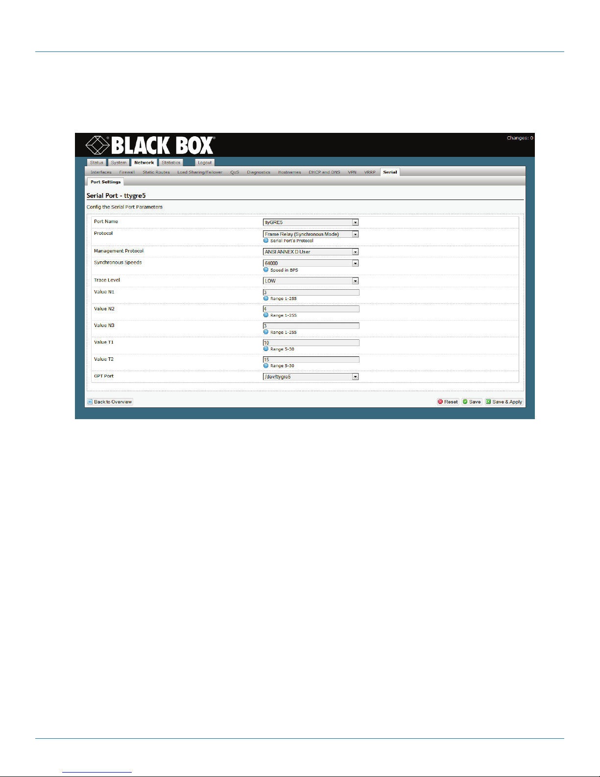
Chapter 5: Configuring the Serial Ports
b. Go to step 10.
7. Serial Port Configuration for Frame Relay (Synchronous Mode).
Figure 5-5. Serial Port Configuration Detail for Frame Relay (Synchronous Mode).
a. On the Serial Port Configuration Detail for Frame Relay (Synchronous Mode) Screen (Figure 5-5), you may see the following
fields:
• Management Protocol: Consult with your network administrator to select one of several available protocols.
• Synchronous Speed: Select a speed for the transmission.
• Trace Level: Low, Medium, High, Critical
• Value N1: For Frame Relay, polling, and so forth.
• Value N2: For Frame Relay, polling, and so forth.
• Value N3: For Frame Relay, polling, and so forth.
• Value T1: For Frame Relay, polling, and so forth.
• Value T2: For Frame Relay, polling, and so forth.
• GPT (Global Path) Port: Select a global path port for the virtual protocol to use, or select custom to type a new global path
name.
b. Go to step 10.
Page 58
724-746-5500 | blackbox.com
Page 59

8. Serial Port Configuration for Frame Relay over IP.
Chapter 5: Configuring the Serial Ports
Figure 5-6. Serial Port Configuration Detail for Frame Relay (IP Mode).
a. On the Serial Port Configuration Detail for Frame Relay (IP Mode) Screen (Figure 5-6), you may see the following fields:
• Management Protocol: Consult with your network administrator to select one of several available protocols.
• Trace Level: Low, Medium, High, Critical
• Local Address: The WRT4000 Series Cellular Wireless Router’s IP address.
• Remote Address: The remote device’s IP address
• Value N1: For Frame Relay, polling, and so forth.
• Value N2: For Frame Relay, polling, and so forth.
• Value N3: For Frame Relay, polling, and so forth.
• Value T1: For Frame Relay, polling, and so forth.
• Value T2: For Frame Relay, polling, and so forth.
• GPT (Global Path) Port: Select a global path port for the virtual protocol to use, or select custom to type a new global path
name.
b. Go to step 10.
9. Serial Port Configuration for Asynchronous Encapsulation.
724-746-5500 | blackbox.com
Page 59
Page 60

Chapter 5: Configuring the Serial Ports
Figure 5-7. Serial Port Configuration Detail for Asynchronous Encapsulation.
a. On the Serial Port Configuration Detail for Asynchronous Encapsulation Screen (Figure 5-7), you may see the following fields:
• Asynchronous Speed: Select a speed for the transmission.
• Flow Control: Hardware, Off, On, or Tx (Transmit) Only
• GPT (Global Path) Name: Select a global path for the virtual protocol to use.
• GPT Type: Select a global path type (Frame Relay, Telnet, and so forth) for the virtual protocol to use.
• GPT Port: Select a global path port for the virtual protocol to use, or select custom to type a new global path name.
• DLCI Number: Get the DLCI number from your network administrator.
• Priority: Immediate, High, Medium, or Low.
b. Go to step 10.
10. When you have finished configuring the serial port protocol, do one of the following:
a. Select the Save & Apply button (in the lower right corner of the screen).
• The changes are saved, and the Serial Port Configuration Screen is redisplayed. The new display includes your changes.
b. Select the Back to Overview button (in the lower left of the screen).
• The changes are discarded, and the Serial Port Configuration Screen is redisplayed.
11. If you wish to reconfigure another protocol on the Serial Port Configuration Screen, select that protocol’s row, and repeat
step 3 through step 10.
12. If you wish to add another protocol for the serial ports, do the following:
a. Select the Add Port button (at the lower left of the list of Port Names).
• The Serial Port Configuration Screen with a Row for a New Protocol (Figure 5-8) is displayed. The protocol does not yet have a
name.
Page 60
724-746-5500 | blackbox.com
Page 61

Chapter 5: Configuring the Serial Ports
Figure 5-8. Serial Port Configuration Screen with a Row for a New Protocol.
b. In the new row, select the Edit button.
• The Serial Port Configuration Detail Screen for a New Protocol (Figure 5-9) is displayed. The protocol does not yet have a name.
Figure 5-9. Serial Port Configuration Detail Screen for a New Protocol.
c. In the Port Name field, select a name from the pulldown list, or select custom and type a new name.
724-746-5500 | blackbox.com
Page 61
Page 62

Chapter 5: Configuring the Serial Ports
d. In the Protocol field, select the protocol that the virtual protocol will support.
The remaining fields on the screen change to support the selected protocol. Return to step 5.
Page 62
724-746-5500 | blackbox.com
Page 63
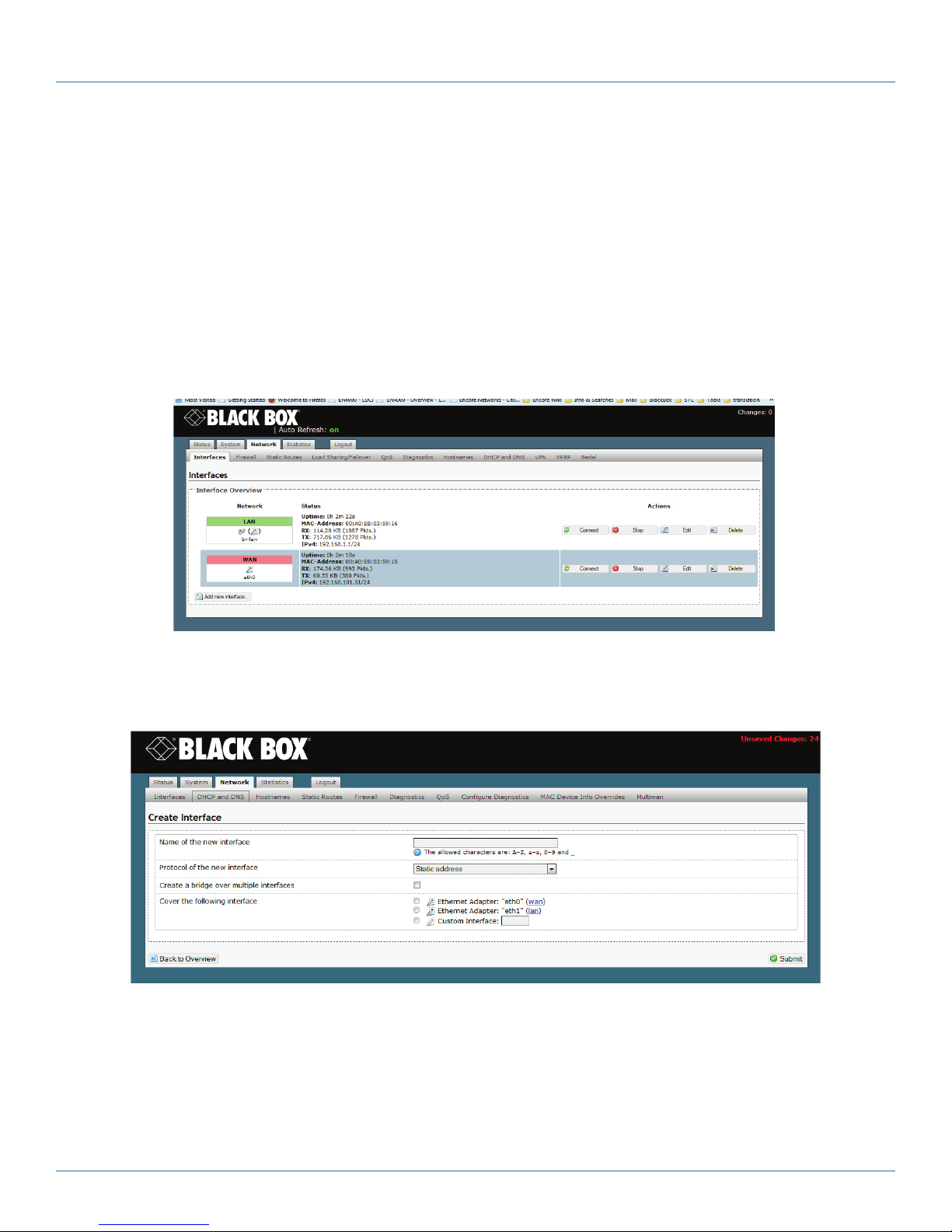
Chapter 6: Configuring Chassis Ports
6. Configuring Chassis Ports
Follow the procedures in this discussion to configure the WRT4000 Series Cellular Wireless Router chassis ports.
Also see Configuring the WRT4000 Series Cellular Wireless Router’s Serial Ports.
6.1 Port Interfaces
Confer with your network administrator to get values for this configuration.
1. Select the Network management area.
2. Select the Interfaces configuration area.
• The WRT4000 Series Cellular Wireless Router Interface Overview Screen is displayed (Figure 6-1).
Figure 6-1. WRT4000 Series Cellular Wireless Router Interface Overview Screen.
3. To define a new interface, select Add New Interface.
• The Screen to Create an Interface is displayed (Figure 6-2).
Figure 6-2. Screen to Create an Interface.
4. Fill out the fields on the Screen to Create an Interface.
5. Select the Submit button (in the lower right corner of the screen) to add the interface.
6. Select the Back to Overview button (in the lower left corner of the screen) to return to the general network interfaces screen.
• The WRT4000 Series Cellular Wireless Router Interface Overview Screen is redisplayed, showing the new interface.
724-746-5500 | blackbox.com
Page 63
Page 64

Chapter 6: Configuring Chassis Ports
6.1.1 Configuring a LAN Port
Confer with your network administrator to get values for this configuration.
1. Select the Network management area.
2. Select the Interfaces configuration area.
• The WRT4000 Series Cellular Wireless Router Interface Overview Screen is displayed (Figure 6-3).
Figure 6-3. WRT4000 Series Cellular Wireless Router Interface Overview Screen.
3. Select the Edit button in the LAN interface row.
4. If necessary, select the General Setup tab.
• The LAN Interface General Setup Screen is displayed (Figure 6-4).
5. After configuring the fields on the screen (including the General Setup items under the DHCP Server heading in the lower
portion of the screen), select the Save & Apply button. Then select the Advanced Settings tab under the DHCP Server heading.
• The LAN Interface DHCP Server Advanced Settings Screen is displayed (Figure 6-5).
Page 64
Figure 6-4. LAN Interface General Setup Screen.
724-746-5500 | blackbox.com
Page 65

Chapter 6: Configuring Chassis Ports
Figure 6-5. LAN Interface DHCP Server Advanced Settings Screen.
6. After configuring the fields for the Advanced Settings tab under the DHCP Server heading, select the Save & Apply button.
Then select the Advanced Settings tab under the Common Configuration heading (in the top portion of the screen).
• The LAN Interface Common Configuration Advanced Settings Screen is displayed (Figure 6-6).
Figure 6-6. LAN Interface Common Configuration Advanced Settings Screen.
7. After configuring the fields for Advanced Settings under the Common Configuration heading, select the Save & Apply button.
Then select the Physical Settings tab.
• The LAN Interface Physical Settings Screen is displayed (Figure 6-7).
724-746-5500 | blackbox.com
Page 65
Page 66

Chapter 6: Configuring Chassis Ports
Figure 6-7. LAN Interface Physical Settings Screen.
8. After configuring the fields on the screen, select the Save & Apply button. Then select the Firewall Settings tab.
• The LAN Interface Firewall Settings Screen is displayed (Figure 6-8).
Figure 6-8. LAN Interface Firewall Settings Screen.
9. After configuring the fields on the screen, select the Save & Apply button.
Page 66
724-746-5500 | blackbox.com
Page 67

Chapter 6: Configuring Chassis Ports
6.1.2 Configuring the WAN Port
Confer with your network administrator to get values for this configuration.
1. Select the Network management area.
2. Select the Interfaces configuration area.
• The WRT4000 Series Cellular Wireless Router Interface Overview Screen is displayed (Figure 6-9).
Figure 6-9. WRT4000 Series Cellular Wireless Router Interface Overview Screen.
3. Select the Edit button in the WAN interface row.
• The WAN Interface General Setup Screen is displayed (Figure 6-10).
Figure 6-10. WAN Interface General Setup Screen.
4. After configuring the fields on the screen, select the Save & Apply button. Then select the Advanced Settings tab.
• The WAN Interface Advanced Settings Screen is displayed (Figure 6-11).
724-746-5500 | blackbox.com
Page 67
Page 68

Chapter 6: Configuring Chassis Ports
Figure 6-11. WAN Interface Advanced Settings Screen.
5. After configuring the fields on the screen, select the Save & Apply button. Then select the Physical Settings tab.
• The WAN Interface Physical Settings Screen is displayed (Figure 6-12).
Figure 6-12. WAN Interface Physical Settings Screen.
6. After configuring the fields on the screen, select the Save & Apply button. Then select the Firewall Settings tab.
• The WAN Interface Firewall Settings Screen is displayed (Figure 6-13).
Page 68
724-746-5500 | blackbox.com
Page 69

Figure 6-13. WAN Interface Firewall Settings Screen.
7. After configuring the fields on the screen, select the Save & Apply button.
Chapter 6: Configuring Chassis Ports
724-746-5500 | blackbox.com
Page 69
Page 70

Chapter 7: Configuring a MultiWAN for the WRT4000 Series Cellular Wireless Router
7. Configuring a MultiWAN for the WRT4000 Series Cellular Wireless Router
The WRT4000 Series Cellular Wireless Router provides wireless and cabled connections to a local area network (LAN) and to
peripheral devices and remote devices.
Follow the procedures in this discussion to configure a multiWAN for the WRT4000 Series Cellular Wireless Router.
Also see Chapter 6, Configuring Chassis Ports in the WRT4000 Series Cellular Wireless Router.
7.1 Use of a MultiWAN
A multiWAN is a group of WAN ports configured to route an IP session over the least busy WAN port in the group, using the
same port until the session is finished. (A multiWAN routes the entire session; it does not determine a route by individual packet.)
Any WAN port in the WRT4000 Series Cellular Wireless Router—including the physical WAN port on the back of the chassis—can
be part of a multiWAN.
A multiWAN connects the network to two or more internet service providers (ISPs).
In Figure 7-1, a wireless WAN port (wan1 or wan2) in each of the WRT4000 Series Cellular Wireless Router’s two wireless cards
connects to a specified wireless network. These connections provide dual-cell loadsharing/failover. That is, they balance the traffic
load when each ISP connection is available, and they allow automatic failover if one ISP connection is dropped.
NOTE: In the example, the wireless WAN ports are named wan1 and wan2. However, your network administrator will choose
names that are meaningful in your network.
Wireless WAN ports (wan1 and wan2 in Figure 7-1) assigned to the same multiWAN must be on separate subnets and must
use different default gateways.
WRT40 01A
Figure 7-1. WRT4000 Series Cellular Wireless Router MultiWAN to Two Wireless Carriers.
Page 70
724-746-5500 | blackbox.com
Page 71

Chapter 7: Configuring a MultiWAN for the WRT4000 Series Cellular Wireless Router
7.2 Configuring a MultiWAN
Confer with your network administrator to get values for this configuration.
To configure multiWAN parameters, do the following:
1. Select the Network management area.
2. Then select the MultiWAN detail tab.
3. If necessary, select the Overview detail tab.
• The MultiWAN Overview Screen is displayed (Figure 7-2).
Figure 7-2. MultiWAN Overview Screen.
NOTE: The multiWAN’s rules for loadsharing use the following hierarchy:
• Rule order
• Policies
• Members
• Interfaces
The lowest items of the hierarchy must be configured first. Each level of the hierarchy builds on a lower level, working up to the
top of the hierarchy. To develop the rules for the multiWAN, work across the lowest row of tabs, left to right:
• First configure the Interfaces (step 4).
• Then organize the interfaces into Members (weighted sets, step 5).
• Develop Policies for the members (step 6).
• Organize the policies into Rules (step 7).
Step 8 and step 9 complete the procedure for building the multiWAN.
4. Select the Interfaces tab.
• The MultiWAN Interface Configuration Summary Screen is displayed (Figure 7-3).
On this screen, you can review the interfaces that constitute the multiWAN. This screen lets you check and track each interface.
In this example, the interfaces are wan1 and wan2. These names correspond to the interfaces wan1 and wan2 on the wireless
cards in Figure 7-1.
NOTE: A multiWAN may have more than two interfaces.
724-746-5500 | blackbox.com
Page 71
Page 72

Chapter 7: Configuring a MultiWAN for the WRT4000 Series Cellular Wireless Router
Figure 7-3. MultiWAN Interface Configuration Summary Screen.
a. Do one of the following on the MultiWAN Interface Configuration Summary Screen:
i. Select the Edit button to revise an interface for this multiWAN.
ii. Type a new interface name in the box to the left of the Add button, and select that button to add an interface.
NOTE: If you try to add an interface that uses a name already listed, the screen will blank the entry and will wait for a new name.
In that case, repeat substep ii.
• In either case, the MultiWAN Interface Configuration Detail Screen is displayed (Figure 7-4).
Figure 7-4. MultiWAN Interface Configuration Detail Screen.
b. On the MultiWAN Interface Configuration Detail Screen, enter values that will determine whether this interface is active. Enter
values for the following fields:
• Enabled (required field; allows the multiWAN to use this interface): Select Yes to enable the interface or No to disable it.
• Test IP (host addresses, to determine whether this interface is active):
Type the host’s IP address. If the interface has more than one host, click the box to the right of the entry field and add another
IP address. Continue until you have entered all the host IP addresses to track for this interface.
NOTE: If there is no value in this field, the interface will always be considered active.
• Test IP Reliability (number of hosts to test to determine whether the interface is active): Type the number of host IP addresses
that must respond to pings. The interface will be considered active when the required number of interfaces respond to pings.
Page 72
724-746-5500 | blackbox.com
Page 73

Chapter 7: Configuring a MultiWAN for the WRT4000 Series Cellular Wireless Router
CAUTION: The number of IP addresses required to respond to pings must be no larger than the number of IP addresses entered
in the Test IP field. Otherwise, the interface will always be considered inactive.
• Ping Count (number of pings for interface test): Enter the number of pings to send to each host IP address listed.
• Ping Timeout (number of seconds for successful response): Enter the number of seconds to wait for a response to a ping.
NOTE: This value should be 2 seconds or longer so that false timeouts are not reported.
• Ping Interval (number of seconds between tests): Enter the number of seconds between pings.
• Interface Down (number of failed tests): Enter the number of failed pings that will make the management system consider the
interface inactive.
• Interface Up (number of successful tests): Enter the number of successful pings that will make the management system consider
an interface active again.
• Reroute (enabling of failover):
- If you set this parameter to 1 (one), this interface will use failover:
When this interface is inactive, its traffic will be rerouted according to the multiWAN’s rules.
- If you leave this field empty (blank) or set it to 0 (zero), this interface will not use failover:
When this interface is inactive, its traffic will not be rerouted according to the multiWAN’s rules.
c. When you have finished configuring this interface, select the Save button.
Then select the Back to Overview button to see the MultiWAN Interface Configuration Summary Screen again (Figure 7-5).
Figure 7-5. MultiWAN Interface Configuration Summary Screen.
d. If you need to configure another interface for the multiWAN, return to step 4a (on page 3).
e. When you have finished configuring all the interfaces for the multiWAN, do one of the following on the MultiWAN Interface
Configuration Summary Screen:
i. Select the Save & Apply button to save the configuration and use it immediately.
ii. Select the Save button to save the multiWAN configuration now and use it after the WRT4000 Series Cellular Wireless Router
is restarted.
iii. Select the Reset button to discard the changes and use the previously saved configuration.
724-746-5500 | blackbox.com
Page 73
Page 74

Chapter 7: Configuring a MultiWAN for the WRT4000 Series Cellular Wireless Router
5. Select the Members tab.
• The MultiWAN Member Configuration Summary Screen is displayed (Figure 7-6). On this screen, you can assign metrics and
weights to develop loadsharing within the multiWAN.
Figure 7-6. MultiWAN Member Configuration Summary Screen.
a. Do one of the following on the MultiWAN Member Configuration Summary Screen:
i. Select the Edit button to revise the loadsharing order and priorities.
ii. Type a member name in the box to the left of the Add button, and select that button to add that member to the multiWAN.
NOTE: If you try to add a member that uses a name already listed, the screen will blank the entry and will wait for a new name.
In that case, repeat substep ii.
• In either case, the MultiWAN Member Configuration Detail Screen is displayed (Figure 7-7).
Figure 7-7. MultiWAN Member Configuration Detail Screen.
Page 74
724-746-5500 | blackbox.com
Page 75

Chapter 7: Configuring a MultiWAN for the WRT4000 Series Cellular Wireless Router
b. On the MultiWAN Member Configuration Detail Screen, enter values to develop a weighted member set. Enter values for the
following fields:
• Interface (required field): Type an interface name for this multiWAN member to use. The interface name must be listed under
Available Interfaces in the lower portion of the screen. (In Figure 7-7, the available interface names are wan1 and wan2.)
• Metric (precedence): Type a value for order of precedence. A low metric has a high priority.
• Weight (load distribution): Type a value to determine loadsharing. A high weight has a high priority.
NOTE: When a packet is tested against the rules, the metric of each active WAN interface is considered.
• If one WAN has a lower metric than all other WANs in the multiWAN, the traffic will failover to that WAN interface.
• If two or more WANs have the same lowest metric, the weights of those WANs are considered. Traffic will pass through those
WANs, using load balancing based on the relative weights assigned to those WANs.
c. When you have finished configuring this multiWAN member, select the Save button; then select the Back to Overview button
to see the MultiWAN Member Configuration Summary Screen.
d. If you need to configure another member for the multiWAN, return to step 5a.
e. When you have configured metrics and weights for all the members of the multiWAN, do one of the following on the
MultiWAN Member Configuration Summary Screen (recall Figure 7-6):
i. Select the Save & Apply button to save the configuration and use it immediately.
ii. Select the Save button to save the multiWAN member configuration now and use it after the WRT4000 Series Cellular Wireless
Router is restarted.
iii. Select the Reset button to discard the changes and use the previously saved configuration.
6. Select the Policies tab.
• The MultiWAN Policy Configuration Summary Screen is displayed (Figure 7-8). On this screen, you can develop policies for the
multiWAN.
Figure 7-8. MultiWAN Policy Configuration Summary Screen.
NOTE: You can leave an unused policy in place on this screen, in case it might be used in the future. (To leave a policy unused,
do not assign it to a rule in step 7b.)
724-746-5500 | blackbox.com
Page 75
Page 76

Chapter 7: Configuring a MultiWAN for the WRT4000 Series Cellular Wireless Router
a. Do one of the following on the MultiWAN Policy Configuration Summary Screen:
i. Select an Edit button to revise a policy.
ii. Type a policy name in the box to the left of the Add button, and select that button to add a policy.
NOTE: If you try to add a policy that uses a name already listed, the screen will blank the entry and will wait for a new name. In
that case, repeat substep ii.
• In either case, the MultiWAN Policy Configuration Detail Screen is displayed (Figure 7-9).
Figure 7-9. MultiWAN Policy Configuration Detail Screen.
b. On the MultiWAN Policy Configuration Detail Screen, add members to develop a policy. Do the following:
i. In the Member Used field, type a member name. The name must be listed under Available Members in the lower portion of the
screen.
ii. If you want to add another member to the policy, click the button to the right of the field. Another field will be displayed; add
another member in that field. Continue until you have included all the members for this policy.
c. When you have finished configuring the policy, select the Save button; then select the Back to Overview button to see the
MultiWAN Policy Configuration Summary Screen.
d. If you need to configure another policy for the multiWAN, return to step 6a.
e. When you have finished configuring the policies for multiWAN configuration, do one of the following on the MultiWAN Policy
Configuration Summary Screen (recall Figure 7-8):
i. Select the Save & Apply button to save the configuration and use it immediately.
ii. Select the Save button to save the multiWAN configuration now and use it after the WRT4000 Series Cellular Wireless Router is
restarted.
iii. Select the Reset button to discard the changes and use the previously saved configuration.
7. Select the Rules tab.
• The MultiWAN Rule Configuration Summary Screen is displayed (Figure 7-10). On this screen, you can define and organize rules
for the multiWAN.
Page 76
724-746-5500 | blackbox.com
Page 77

Chapter 7: Configuring a MultiWAN for the WRT4000 Series Cellular Wireless Router
Figure 7-10. MultiWAN Rule Configuration Summary Screen.
a. Do one of the following on the MultiWAN Rule Configuration Summary Screen:
i. Select an Edit button to revise a rule for the multiWAN.
ii. Type a new rule name in the box to the left of the Add button, and select that button to add a rule.
NOTE: If you try to add a rule that uses a name already listed, the screen will blank the entry and will wait for a new name. In that
case, repeat substep ii.
• In either case, the MultiWAN Rule Configuration Detail Screen is displayed (Figure 7-11).
Figure 7-11. MultiWAN Rule Configuration Detail Screen.
b. On the MultiWAN Rule Configuration Detail Screen, enter values for the following parameters:
• Source Address (originating IP address, whether local or remote): Type a network range for IP addresses (such as a.b.c.0/24,
where a.b.c represents the local network). You may also type a single IP address, or this field may be left blank.
724-746-5500 | blackbox.com
Page 77
Page 78

Chapter 7: Configuring a MultiWAN for the WRT4000 Series Cellular Wireless Router
• Source Port (originating port, whether outbound or inbound): Type a port range. You may also type a single port number,
or this field may be left blank.
• Destination Address (goal IP address, whether local or remote): Type a network range for IP addresses (such as d.e.f.0/24,
where d.e.f represents the remote network). You may also type a single IP address, or this field may be left blank.
• Destination Port (goal port, whether outbound or inbound): Type a port range. You may also type a single port number, or this
field may be left blank.
• Protocol (IP transport protocol): Select a protocol from the list.
• Policy Assigned (required): Type a policy name that this rule will use, or set the value to default. The policy name must be listed
under Available Policies. If you select default, the rule uses the standard routing table.
• Equalize (how to apply loadsharing): If you want load balancing to cycle through the host networks, check the Equalize box. If
you do not check the box, the rule will use the standard routing table, and load balancing might be based on destinations.
c. When you have finished configuring this rule, select the Save button; then select the Back to Overview button to see the
MultiWAN Rule Configuration Summary Screen again (Figure 7-12).
Figure 7-12. MultiWAN Rule Configuration Summary Screen.
d. If you need to configure another rule for the multiWAN, return to step 7a.
e. After you have configured all the rules, confer with your network administrator to determine the order for the rules.
f. Use the arrows in the Sort column of the MultiWAN Rule Configuration Summary Screen to move a rule up or down in the list,
so that the rules are applied in the determined order.
Page 78
724-746-5500 | blackbox.com
Page 79

Chapter 7: Configuring a MultiWAN for the WRT4000 Series Cellular Wireless Router
NOTE: The rules test uses a top-down matching routine:
i. When a packet enters the WRT4000 Series Cellular Wireless Router, the packet’s header information is tested against the
first rule in the list.
ii. Within the rule, the packet is tested for a match against each parameter, in the following order (corresponding to
headings from left to right in Figure 7-12):
• Source Address
• Source Port
• Destination Address
• Destination Port
• Protocol
If a parameter is blank (such as Source Port for the first rule in Figure 7-12), that parameter is skipped.
iii. If the packet matches all parameters for the rule, the rule’s assigned policy is applied to the packet.
iv. If the packet does not match the rule, the packet is tested against the next rule in the list. (Return to substep ii.)
v. If a packet matches no rule, the standard routing table is used to send the packet toward its destination.
g. When you have finished configuring the rules for multiWAN configuration, do one of the following on the MultiWAN Rule
Configuration Summary Screen (recall Figure 7-12):
i. Select the Save & Apply button to save the configuration and use it immediately.
ii. Select the Save button to save the multiWAN configuration now and use it after the WRT4000 Series Cellular Wireless Router is
restarted.
iii. Select the Reset button to discard the changes and use the previously saved configuration.
8. When you have finished configuring all the multiWAN configuration summary screens (Figure 7-3, Figure 7-6, Figure 7-8, and
Figure 7-10), select the Overview tab to navigate to the MultiWAN Overview Screen again (Figure 7-13).
9. Then do one of the following on the MultiWAN Overview Screen:
a. Select the Save button to save the multiWAN configuration now and use it after the WRT4000 Series Cellular Wireless Router
has been restarted.
b. Select the Reset button to discard the changes and use the previously saved configuration.
• When a packet enters the WRT4000 Series Cellular Wireless Router, it will be tested and directed on its path according to the
rules.
Figure 7-13. MultiWAN Overview Screen.
724-746-5500 | blackbox.com
Page 79
Page 80

Chapter 8: Virtual Private Networks
8. Virtual Private Networks
One of the principal features of routers is their support of virtual private networks (VPNs). This document discusses transmission
security, VPNs, and how the WRT4000 Series Cellular Wireless Router sets up and uses a VPN connection.
A VPN is a secure encrypted transmission between two or more private endpoints over a public network. Tunneling—encapsulating data within secure packets—isolates the private data from other traffic carried by the public network, providing secure transport over the network. The public network uses the header information in the packets to deliver the packets to their destination.
When the destination endpoint receives the packets, it authenticates and unpackages them, and decrypts the data.
Use of VPNs allows for dynamic, temporary connections instead of permanent physical connections. This allows an organization
to build a private network over the public IP network, which reduces costs for the number of leased lines that the organization
needs to maintain. In addition, connection (via VPN client software) over the internet allows business travelers to communicate
with the office network from any site that has a connection to the internet.
The WRT4000 Series Cellular Wireless Router supports VPN’s IP Security Protocol (IPsec, described in RFC 2401) and supports
IPsec’s use of the Internet Key Exchange, version 1 (IKEv1) and version 2 (IKEv2). Any WRT4000 Series Cellular Wireless Router
device can use IKEv1 and IKEv2 at the same time, but not on the same port at the same time.
See the following sections:
• Section 8.1, VPN Configuration in the WRT4000 Series Cellular Wireless Router
• Section 8.2, Testing and Tracking Virtual Private Networks Connections
• Section 8.3, VPN Basics
• Section 8.4, Developing a Virtual Private Network
8.1 VPN Configuration in the WRT4000 Series Cellular Wireless Router
VPN configuration requires collection of a fair amount of information before the actual configuration can be performed. See the
following:
• Section 5.1.1, Configuring VPNs on the WRT4000 Series Cellular Wireless Router
• Section 5.1.2, Starting the Tunnel
8.1.1 Configuring VPNs on the WRT4000 Series Cellular Wireless Router
NOTE: It is important to plan your virtual private network. Before configuring the WRT4000 Series Cellular Wireless Router’s IPsec
VPN tunnels, study the material discussed in Basics of Virtual Private Networks (on page X) and in Developing a Virtual
Private Network (on page X).
Do the following to configure the WRT4000 Series Cellular Wireless Router’s IPsec VPN tunnels:
1. Open a browser and log into the WRT4000 Series Cellular Wireless Router.
NOTE: For details, see the section Logging In, in Section X.X, Configuring the WRT4000 Series Cellular Wireless Router.
1. On the WRT4000 Series Cellular Wireless Router’s browser-based management system, select Network, VPN.
• The List of Configured IPsec VPN Tunnels is displayed (Figure 8-1).
CAUTION: The IP addresses shown in the figures are examples. Consult your network administrator for IP addresses to use in your
network.
Page 80
724-746-5500 | blackbox.com
Page 81
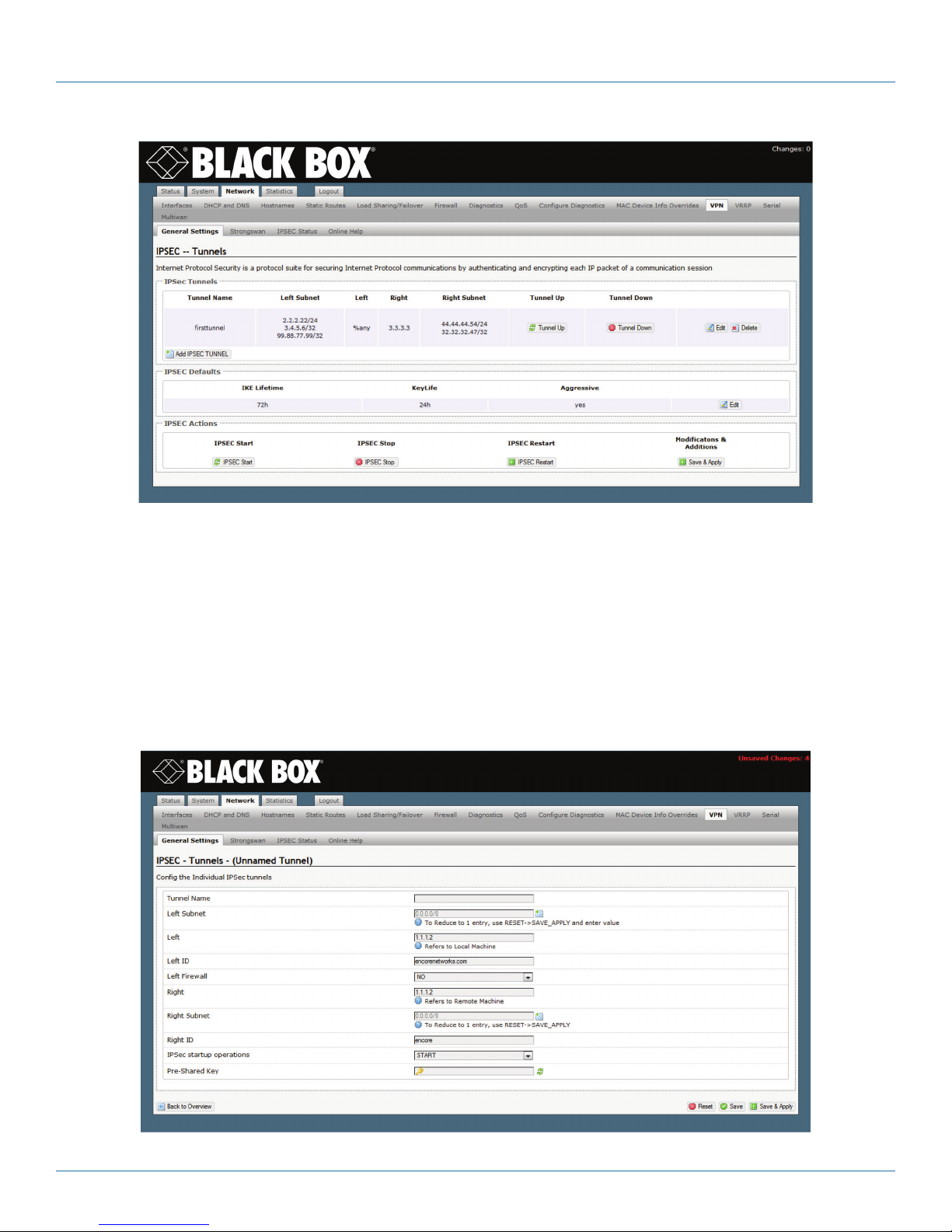
Chapter 8: Virtual Private Networks
Figure 8-1. List of Configured IPsec VPN Tunnels.
2. Review the configured VPN tunnels.
NOTE: In the VPN tunnel configuration screens, “left” indicates “local” (that is, it indicates the WRT4000 Series Cellular Wireless
Router) and “right” indicates “remote” (the device at the other end of the connection).
3. You may need to add or revise some VPN tunnels to reflect changes in your network configuration. If so, do the following, for
as many VPN tunnels as needed for your WRT4000 Series Cellular Wireless Router:
a. To add an IPsec VPN tunnel, select the button Add IPsec Tunnel (below the list of Tunnel Names).
b. To revise a VPN tunnel configuration, select the Edit button on the right side of that VPN tunnel’s row.
• In either case, the screen for Configuring an IPsec VPN Tunnel is displayed (Figure 8-2).
Figure 8-2. Configuring an IPsec VPN Tunnel.
724-746-5500 | blackbox.com
Page 81
Page 82

Chapter 8: Virtual Private Networks
4. Configure or revise the settings for the VPN tunnel. Confer with your network administrator for values that the VPN tunnel will
use.
• The following are sample values:
CAUTION: Do not use these values. They are shown here only as examples of entries. Confer with your network administrator for
IPsec VPN values.
• Tunnel Name: Tunnel 01
• Left Subnet: a.b.c.0/24 (where a.b.c indicates the local private network)
• Left: e.f.g.h (where e.f.g.h is the local WRT4000 Series Cellular Wireless Router’s public IP address)
• Left ID: e.f.g.h (where this ID reflects the public IP address)
• Left Firewall: NO
• Right: i.j.k.l (where i.j.k.l is the remote router’s public IP address)
• Right Subnet: m.n.p.0/24 (where m.n.p indicates the remote private network)
• Right ID: i.j.k.l (where this ID reflects the public IP address)
• IPsec Start-Up Operations: ROUTE
• Pre-Shared Key: 24xn42aa93lw (Do not use this pre-shared key; is it merely an example.)
NOTE: The preshared key includes the lowercase letter “l” (ell); do not mistake it for the number “1” (one).
5. When you have finished configuring the VPN tunnel, do one of the following:
a. To leave the configuration screen without changing or saving the VPN tunnel, select the Back to Overview button at the lower
left of the screen.
• The List of Configured IPsec VPN Tunnels is redisplayed without changes.
b. To save the configuration, select the Save & Apply button (in the lower left corner of the screen).
• The new VPN tunnel configuration is saved. The List of Configured IPsec VPN Tunnels is redisplayed (Figure 6-3). The new tunnel
is at the bottom of the list.
Page 82
724-746-5500 | blackbox.com
Page 83

Chapter 8: Virtual Private Networks
Figure 8-3. List of Configured IPsec VPN Tunnels Including the Tunnel Named Tunnel 01.
6. To configure IPsec for the WRT4000 Series Cellular Wireless Router, select the Edit button at the far right of the row under
IPsec Defaults.
724-746-5500 | blackbox.com
Page 83
Page 84

Chapter 8: Virtual Private Networks
• The screen for Configuring IPsec Defaults is displayed (Figure 8-4).
NOTE: Confer with your network administrator to determine the settings for the WRT4000 Series Cellular Wireless Router’s IPsec
VPN connections. Make sure you select options that are compatible with the version of the Internet Key Exchange (IKEv1 or
IKEv2) that you want to use.
• The following are sample values:
CAUTION: Do not use these values. They are shown here only as examples of entries. Confer with your network administrator for
IPsec VPN values.
• Phase 1:
- IKE Lifetime: 72h [72 hours]
- Key Life: 8h [8 hours]
- ReKey Margin: 0h [0 hours; thus no kilobytes rekeying]
- Keying Tries: 2 [the default value]
- Key Exchange: IKEv1
- Auth [Authentication]: secret
- Aggressive Mode: No (“No” indicates use of main mode.)
Page 84
Figure 8-4. Configuring IPsec Defaults.
724-746-5500 | blackbox.com
Page 85

Chapter 8: Virtual Private Networks
- IKE Encryption Protocol: 3DES
- IKE Authentication Protocol: SHA1
- IKE DH [Diffie–Hellman] Group: Group2
• Phase 2 (uses perfect forward secrecy):
- ESP Encryption Protocol: 3DES
- ESP Authentication Protocol: SHA1
- ESP DH [Diffie–Hellman] Group: Group2
- DPD [Dead Peer Detection] Action: Restart
- DPD [Dead Peer Detection] Delay: 20s [seconds]
- DPD [Dead Peer Detection] Timeout: 120s [seconds]
- Re-Key: No
- Re-Auth: No
- Responder: No (This means that the local WRT4000 Series Cellular Wireless Router will initiate the tunnel.)
7. When you have finished configuring IPsec defaults, select the Save & Apply button in the lower right corner of the screen.
• The IPsec defaults are saved, and the List of Configured IPsec VPN Tunnels is redisplayed (recall Figure 8-3).
8. When you have configured all VPN tunnels for the WRT4000 Series Cellular Wireless Router, select the Save & Apply button
under Modifications and Additions (at the lower right of the screen for the List of Configured IPsec VPN Tunnels).
NOTE: The router at the other end of the VPN tunnel must also be configured for this connection.
9. Do one of the following:
a. If this is the first IPsec VPN activity since system start-up, select the IPSEC Start button (at the lower left of the management
window).
b. If IPsec VPN tunnels are already running, select the IPSEC Restart button.
• In either case, the new IPsec VPN tunnel is started.
NOTE: After the IPsec Start button has been selected, you can select a VPN tunnel’s Tunnel Down button to bring that tunnel
down. Then you can select its Tunnel Up button to restart the VPN tunnel.
You can use the IPsec Stop button to stop all VPN tunnels. (The VPN packet transmissions will be dropped.) When you are ready
to resume use of the tunnels, select the IPsec Restart button to re-initiate all IPsec VPN tunnels.
8.1.2 Starting the Tunnel
If you performed step 9a or step 9b in the procedure for Configuring VPNs on the WRT4000 Series Router, the tunnel is already
up, and you may skip this section.
1. In the List of Configured IPsec VPN Tunnels (recall Figure 5-3), select the Tunnel Up button in the row for the tunnel named
Tunnel 01.
• The selected VPN tunnel (Tunnel 01) is started.
8.2 Testing and Tracking VPN Connections
8.2.1 Testing VPN Connections
Do the following to test a VPN Connection:
1. Open a browser and log into the WRT4000 Series Cellular Wireless Router.
NOTE: For details, see Section 4.1.3, Logging In, in Chapter 4, Configuration.
724-746-5500 | blackbox.com
Page 85
Page 86

Chapter 8: Virtual Private Networks
2. On the WRT4000 Series Cellular Wireless Router management system, select the Network tab.
3. Under Networks, select the Diagnostics tab.
• The Diagnostics Screen is displayed (Figure 8-9).
Figure 8-5. Diagnostics Screen.
4. Look at the ping set-up area on the left of the screen (Figure 8-10), under the heading Network Utilities.
blackbox.com
Figure 8-6. Ping Set-Up Area (Detail of Diagnostics Screen).
5. In the top field, enter the ping destination.
NOTE: The destination can be entered as an IP address or as a URL (a website path and name).
6. In the bottom left-hand box, pull down a menu to select IPv4 or IPv6.
NOTE: If you typed an IP address in step 5, the IP version you select here must match that IP address’s format.
7. In the bottom right-hand box, select the Ping button.
Page 86
724-746-5500 | blackbox.com
Page 87

Chapter 8: Virtual Private Networks
• If the ping is successful, the screen displays ping statistics, indicating that the VPN tunnel is active (Figure 8-11).
Figure 8-7. Messages Showing Successful Ping.
• If the ping is unsuccessful, the screen indicates that no acknowledgments were returned. That means that there is no
communication (Figure 8-12).
NOTE: If the ping is unsuccessful, check the connections and IP address, and repeat step 5.
Figure 8-8. Message Showing Unsuccessful Ping.
8.2.2 Tracking VPN Connections
There are two ways to track VPN connections on the WRT4000 Series Cellular Wireless Router:
• Tracking specific information
• Tracking General VPN Activity
8.2.2.1 Tracking Specific Information
1 Select Network, VPN, StrongSwan to see the List of VPN Tunnel Configuration Scripts (Figure 8-9).
CAUTION: This screen is only for information. Do not modify the script. All changes must be made through the menus on the
WRT4000 Series Router management screens.
724-746-5500 | blackbox.com
Page 87
Page 88

Chapter 8: Virtual Private Networks
Figure 8-9. List of VPN Tunnel Configuration Scripts.
2. Select Network, VPN, IPsec Status to see which IPsec VPN tunnels are up and active (Figure 8-10).
Figure 8-10. Status of IPsec VPN Tunnels.
3 Select Network, VPN, Online Help to link to a site for more information about VPN tunnels (Figure 8-11).
4. Select the first link shown in Figure 5-11 to see a StrongSwan page that shows a test network (Figure 8-12). You may select
items on that page for details of the configuration.
Page 88
Figure 8-11. Screen for Link to Online Help.
724-746-5500 | blackbox.com
Page 89

Chapter 8: Virtual Private Networks
strongSwan UML Texts/ikev2/net2net-psk
Test ikev2/net2net-psk
Description
A connection between the subnets behind the gateways moon and sun is set up.
The authentication is based on Preshared Keys (PSK). When the IP tunnel is successfully
established, leftfirewall=yes automatically inserts iptables-based firewall rules that let pass
the tunneled traffic. To test both tunnel and firewall, client alice behind gateway moon
pings client bob located behind gateway sun.
gateway
moon
gateway
sun
client
alice
eth0
10.1.0 .10
et h1
10.1.0 .1
eth0
192 .16 8. 0.1
eth0
192 .16 8. 0.2
eth0
192 .16 8. 0.150
Web server
winnetou
et h1
10.2.0.1
et h1
10.2. 0.10
client
bob
moon
• ipsec.conf • ipsec statusall • ip-s xfrm policy
• ipesec.secrets • ipsec listall • ip-s xfrm state
• ipsec.sql • auth.log • ip route list table 220
• strongswan.conf • daemon.log • iptables -L
sun
• ipsec.conf • ipsec statusall • ip-s xfrm policy
• ipesec.secrets • ipsec listall • ip-s xfrm state
• ipsec.sql • auth.log • ip route list table 220
• strongswan.conf • daemon.log • iptables -L
-
Figure 8-12. Web Page for StrongSwan Test Network.
724-746-5500 | blackbox.com
Page 89
Page 90

Chapter 8: Virtual Private Networks
5. Select the second link shown in Figure 8-11 to see a StrongSwan page that discusses VPN tunnel configuration (Figure 8-13).
Figure 8-13. Web Page for StrongSwan General Connection Parameters (Partial Display).
8.2.2.2 Tracking General VPN Activity
1. On the WRT4000 Router’s management system, select the Status tab.
2. Under Status, select the System Log tab.
• The System Log is displayed (Figure 8-14), showing a line-by-line log of the router’s activities. You can review the IPsec VPN
activities listed in this file.
Page 90
724-746-5500 | blackbox.com
Page 91

Chapter 8: Virtual Private Networks
Figure 8-14. System Log (Partial Display).
NOTE: The System Log is live; it shows activity up to the second the second that you open it. Although the file continues
recording information while it is open, it will not shownew information until you refresh the browser window.
The file is not permanent; it refreshes when the WRT4000 Series Router reboots.
724-746-5500 | blackbox.com
Page 91
Page 92

Chapter 8: Virtual Private Networks
8.3 VPN Basics
This section discusses basic principles and operations in Virtual Private Networks.
A VPN device encapsulates information into IP packets, and can perform as a VPN gateway over public networks that use IP. As a
VPN gateway, a VPN device can perform IPsec tunnel initiation, IPsec tunnel termination, and IPsec passthrough. Those processes
use IPsec for VPN security, performing the functions listed in Table 8-1.
Table 8-1. IPsec Components Used in the WRT4000 Series Cellular Wireless Router.
Function Protocols Acronym Standard
Key Exchange Internet Key Exchange IKE version 1: RFC 2409
version 2: RFC 5996
Internet Security Association
and Key Management Protocol
Encryption Data Encryption Standard DES FIPS PUB 46-2
Triple Data Encryption Standard 3DES SP 800-67, Revision 1 (per FIPS
Advanced Encryption Standard AES FIPS PUB 197
Security Protocols Encapsulating Security Payload ESP RFC 2406
Authentication Header AH RFC 2402
Authentication Hashed Message Authentication
Code: Message Digest 5
Hashed Message Authentication
Code: Secure Hash Algorithm 1
Hashed Message Authentication
Code: Secure Hash Algorithm 3
ISAKMP RFC2408
PUB 140-2)
HMAC MD5 RFC 1321;
For use of MD5 within ESP and
AH: RFC 2403
HMAC SHA-1 RFC 2404
HMAC SHA-3 FIPS PUB 180-4
1
1
Each Request for Comments (RFC) is from the Internet Engineering Task Force (IETF). Each Federal Information Processing
Standard Publication (FIPS PUB) and each Special Publication (SP) is from the National Institute of Standards and Technology
(NIST).
The WRT4000 Series Cellular Wireless Router can implement IKEv1 or IKEv2 VPN tunnels with any other IPsec compliant VPN
gateway or VPN client. The WRT4000 Series Cellular Wireless Router supports the following tunnel modes:
• Tunnel initiation: The device receives packets from a local user terminal. The device encapsulates the packets according to the
IPsec user policy, establishes a VPN tunnel across the public network to a remote VPN gateway, and sends the packets across
the VPN tunnel toward their destination.
• Tunnel passthrough: The device receives IPsec-encapsulated packets from a client VPN terminal, and provides transparent
forwarding of the IP packets according to the IPsec user policy. The device sends the packets across the public network without
repackaging them.
• Tunnel termination: The device terminates (accepts) an IPsec tunnel initiated by a remote VPN gateway or VPN client across the
public network. The device authenticates and unpackages the tunnel’s packets, and delivers them to the destination terminal.
(To perform tunnel termination, the device must maintain a table of VPN users that function as prospective tunnel initiators; see
The IP Policy Table.)
See the following:
• A Simple Virtual Private Network
• Tunnel Modes
• Tunnel Support
Page 92
724-746-5500 | blackbox.com
Page 93

Chapter 8: Virtual Private Networks
• Internet Key Exchange
8.3.1 A Simple Virtual Private Network
Figure 8-15 illustrates two WRT4000 Series Cellular Wireless Routers functioning as VPN gateways over the IP network.
LAN
(4.4.4.x)
Laptop terminal
1.1.1.2
LAN
(1.1.1.x)
WRT4001A
#1
1.1.1.1
Tunnel over
IP (2.2.2.x)
2.2.2.1
Internet
(IP network)
Tunnel over
IP (3.3.3.x)
3.3.3.1
WRT4001A
#2
4.4.4.1
Terminal
IP
4.4.4.2
Figure 8-15. WRT4000 Series Cellular Wireless Routers as VPN Gateways.
Figure 8-16 shows a simplified example of the WRT4000 Series Cellular Wireless Router’s encryption and encapsulation of data.
NOTE: The transmission shown in Figure 8-16 originates from the laptop terminal (IP address 1.1.1.2) shown in Figure 8-14, and is
destined for the desktop terminal (IP address 4.4.4.2) in Figure 8-15.
Packets coming into
WRT4001A #1 from
terminal 1.1.1.2
Source endpoint’s
internal IP address
Packet A Packet C
Destination endpoint’s
internal IP address
Data
Packet B
Packets exiting WRT4001A #1
toward terminal 4.4.4.2
Packet AA
Source gateway’s
internal IP address
Figure 8-16. Sample IPsec Encryption and Encapsulation,
encryption
Packet BB
Encrypted
information
Destination gateway’s
internal IP address
724-746-5500 | blackbox.com
encryptionencryption
Packet CC
Page 93
Page 94

Chapter 8: Virtual Private Networks
8.3.2 Tunnel Modes
The WRT4000 Series Cellular Wireless Router supports the following modes for VPN tunnels:
• Tunnel Initiation
• Tunnel Termination
• Tunnel Passthrough
8.3.2.1 Tunnel Initiation
The WRT4000 Series Cellular Wireless Router can initiate a VPN tunnel, using IKEv1 or IKEv2, to any other IPsec compliant VPN
gateway. When a local user originates packets to the WRT4000 Series Cellular Wireless Router, and the packets need to travel
over a VPN tunnel, the WRT4000 Series Cellular Wireless Router searches its database for an appropriate VPN policy and VPN
profile.
When an appropriate VPN policy and VPN profile have been determined, the WRT4000 Router contacts the remote VPN gateway
specified by the profile, and negotiates a security association (SA). When the gateways agree on an SA and set up a VPN tunnel,
the WRT4000 Series Cellular Wireless Router encapsulates the packets according to the policy, and sends them across the public
network. When the remote VPN gateway receives the packets, it forwards them to the remote destination.
NOTE: In order to use a VPN tunnel, the combination of origin and destination must conform to a VPN policy. Otherwise, the
request will be rejected.
8.3.2.2 Tunnel Termination
When a remote VPN gateway initiates a VPN tunnel, the WRT4000 Series Cellular Wireless Router acts as a tunnel terminator. The
WRT4000 Series Cellular Wireless Router looks for matches against the following items:
• IDs
• Preshared key
• Peer (remote) user ID. This can be a group ID or a single ID.
If the values match a VPN policy record, the WRT4000 Series Cellular Wireless Router accepts the tunnel termination. Then the
WRT4000 Series Cellular Wireless Router negotiates the key, and accepts or rejects the proposals presented by the initiating VPN
gateway. If the remote user’s ID matches a record in the WRT4000 Series Cellular Wireless Router’s database, the WRT4000 Series
Cellular Wireless Router agrees to terminate the tunnel.
In Figure 5-16, a remote VPN user (User x) wishes to communicate with PC 1, so User x initiates a VPN tunnel to the WRT4000
Series Cellular Wireless Router’s external IP address. Because the remote user’s ID matches a record in the router’s database, the
router agrees to terminate the VPN tunnel. (Figure 5-16 shows this VPN tunnel as a red dotted line.)
Because the remote user wishes to communicate with PC 1, the WRT4000 Series Cellular Wireless Router opens the VPN packets,
decrypts them, and passes the information to PC 1.
Page 94
724-746-5500 | blackbox.com
Page 95

LAN
(1.1.1.x)
Chapter 8: Virtual Private Networks
PC 1
1.1.1.1
PC 2
WRT4001A
User x
(PC)
2.2.2.1
DSL
modem
Tunne l
over IP
Internet
(IP Network)
Figure 8-17. WRT4000 Series Cellular Wireless Router Terminating Tunnel from VPN Client.
Table 8-9 lists sample parameters to support tunnel termination for a remote VPN user.
Table 8-2. Sample Remote User Record.
Field Sample Value
Peer ID (Remote User ID) a1234 @ blackbox.com
Preshared Key ***********
Profile Group 1,2,4,5
NOTE: The choices for profile group can include up to four VPN profiles. The
WRT4000 Series Cellular Wireless Router chooses the first profile that the peer
ID matches.
One of the profile-group choices can be a wildcard—any profile listed in the
VPN profile database. You may list VPN profiles before a wildcard, but there is
no need to list any profiles after a wildcard.
Certificate ***********
NOTE: The remote user’s IP address does not need to be known in advance.
8.3.2.3 Tunnel Passthrough
Tunnel passthrough is used when a remote or local VPN user sends IPsecencapsulated packets to the WRT4000 Series Cellular
Wireless Router. In passthrough mode, the originating device sets up the VPN tunnel, so the originating device is the VPN
endpoint, and the WRT4000 Series Cellular Wireless Router is merely a gateway. The WRT4000 Series Cellular Wireless Router
gateway uses its VPN policy to provide transparent forwarding of the VPN endpoint’s IP packets.
Tunnel passthrough occurs most often when packets are received from a VPN client. If a remote user is using VPN client software,
the client sets up a VPN tunnel through the WRT4000 Series Cellular Wireless Router to a remote network. In this case, the
WRT4000 Series Cellular Wireless Router does not initiate a new VPN tunnel; it uses passthrough mode to carry the tunnel created by the VPN client (which is the VPN endpoint in this scenario).
724-746-5500 | blackbox.com
Page 95
Page 96

Chapter 8: Virtual Private Networks
8.3.3 Tunnel Support
In some situations, a single VPN tunnel can support more than one user. See the following:
• Tunnel Sharing
• Tunnel Switching
• Split Tunneling
8.3.3.1 Tunnel Sharing
More than one VPN profile can specify the same local and remote VPN gateways to reach its remote endpoint. If two such profiles are active at the same time, they are using the same tunnel between the gateways for their VPN connections to different
endpoints. This is called tunnel sharing (or tunnel multiplexing).
8.3.3.2 Tunnel Switching
A remote endpoint can initiate a VPN tunnel into the network. If the remote endpoint wishes to communicate with a destination
endpoint that is outside the network, the WRT4000 Series Cellular Wireless Router checks to see whether there is a VPN profile
describing a tunnel to the requested destination. If so, the router initiates a VPN tunnel to that destination, and routes the traffic
from the initiating endpoint to the destination. This is called tunnel switching.
In Figure 8-18 (an expansion of Figure 8-17), a remote VPN user (User x) wishes to communicate with the network’s VPN host,
but does not want to connect a VPN tunnel to the host itself. So User x initiates a tunnel to the WRT4000 Series Cellular Wireless
Router’s external IP address. Because the remote user’s ID matches a record in the router’s database, the router agrees to terminate the tunnel. (Figure 5-18 shows this VPN tunnel as a red dotted line.)
The remote user wishes to communicate with the VPN host, so the WRT4000 Series Cellular Wireless Router accepts and decrypts
the client’s VPN packets. Then the router initiates a tunnel to the VPN host, and passes the client’s packets to the VPN host.
(Figure 8-18 shows this tunnel as a black dotted line.)
Tunnel switching also hides the VPN client’s IP address.
LAN
(1.1.1.x)
PC 1
1.1.1.1
PC 2
LAN
(100.0.0.x)
VPN host
WRT4001A
2.2.2.1
100.0.0.1
Tunne l
over IP
(2.2.2.x)
Tunne l
over IP
3.3.3.x
3.3.3.1
User x
(PC)
DSL
modem
Tunne l
over IP
Internet
(IP Network)
Figure 8-18. WRT4000 Series Cellular Wireless Router Tunnel Switching between VPN Client and VPN Host
Page 96
724-746-5500 | blackbox.com
Page 97

Chapter 8: Virtual Private Networks
8.3.3.3 Split Tunneling
The WRT4000 Series Cellular Wireless Router can route VPN traffic through VPN tunnels and can route non-VPN traffic outside
these tunnels, on the same line. The router uses the IP policy table to determine whether to route traffic through or outside a
VPN tunnel.
The router performs split tunneling automatically and dynamically.
8.3.4 Internet Key Exchange
The WRT4000 Series Cellular Wireless Router uses the Internet Key Exchange (IKE) protocol to provide secure
transmission between VPN endpoints. IKE negotiates security associations (SAs) policies that establish a protected, authenticated
connection for data transmission.) IKE can be used to do the following:
• Set up virtual private networks (VPNs).
• Provide a remote user secure access to a network. (The remote user’s IP address does not need to be known in advance.)
• Negotiate SAs (and hide identities) for VPN client endpoints.
There are some differences between IKE Version 1 (IKEv1) and IKE Version 2 (IKEv2). The WRT4000 Series Cellular Wireless Router
supports use of IKEv1 and IKEv2 at the same time, but not on the same port at the same time.
NOTE: All IKEv2 VPN connections work well across a device that performs network address translation (NAT). However, an IKEv1
VPN connection must use an appropriate path out of the LAN:
• When an IKEv1 VPN connection uses the Encapsulating Security Payload (ESP) protocol, the connection can cross a device that
performs NAT.
• When an IKEv1 VPN connection uses the Authentication Header (AH) protocol, the connection must not cross a device that performs NAT.
8.3.4.1 Perfect Forward Secrecy
Perfect forward secrecy (PFS)—the use of uniquely derived keys to establish security associations—is an important feature of the
IKE protocol. PFS comprises the following principles:
• Discovery of a key endangers only transmissions protected by that key; so
• Material used to derive one key cannot be used to derive additional keys;
and
• No key can be used to derive another key.
8.3.4.2 IKE Version 1
The Internet Key Exchange protocol, version 1, has two phases:
• Phase 1 is used for key exchange. In this phase, IKE negotiates the following items to establish a Security Association for Phase
2:
- The encryption algorithm
- The hash algorithm
- The authentication method
- The Diffie–Hellman group
• Phase 2 negotiates an SA for services in the transmission. Then this phase is used for data transmission.
724-746-5500 | blackbox.com
Page 97
Page 98

Chapter 8: Virtual Private Networks
IKE Version 1 Details
IKEv1 maintains perfect forward secrecy in the way it performs the following:
• IKE uses a Diffie-Hellman (DH) exchange to set up phase 1. (A DH exchange protects the identities of the originator and the
recipient.) Phase 1 can use main mode or aggressive mode (but not both).
Phase 1 establishes an SA for phase 2, as follows:
- The originator presents proposals for the SA. (The originator may send an unlimited number of proposals; the recipient can limit
the number it will consider.)
- The recipient chooses one proposal and sends its response. The recipient cannot change the proposal. If the originator notices
that the proposal has changed in any way, the originator refuses the response.
- When the originator accepts the response, the SA is set up for phase 2.
• In phase 2, IKE establishes an SA for data transmission. as follows:
- Phase 2 negotiates for services that will be used, such as IPsec.
- When the phase 2 SA is ready for data transmission, IKE deletes the SA that phase 1 had established.
- In the SA for data transmission, quick mode is used for transmission. Both sides of the connection can transmit data. Instead of
extensive authentication, which consumes time and CPU resources, the SA now uses cookies for authentication. The cookie
order established in phase 1 (originator vs. recipient) is always used; the cookies do not change order when the transmission
direction changes.
NOTE: Each IKEv1 phase has a fixed lifetime. The lifetime can be defined in units of time, number of transmissions, or total
amount of transmission (in kilobytes). A phase’s lifetime cannot be increased after the phase has started.
8.3.4.3 IKE Version 2
The WRT4000 Series Cellular Wireless Router implements the Internet Key Exchange protocol, version 2, in conformance with IETF
RFC 5996.
IKEv2 simplifies key exchanges:
• IKEv2 does not use IKEv1’s main mode, aggressive mode, or quick mode. IKEv2 uses a single standard mode.
• Negotiation for set-up has reduced from a minimum of nine exchanges in IKEv1 to a minimum of four exchanges in IKEv2.
• IKEv2 uses only four types of messages, regardless of the number of exchanges.
There are some other principal changes for IKEv2:
• VPN policies are simpler than in IKEv1.
• IKEv2 uses less bandwidth than IKEv1 uses.
• IKEv2 has built-in NAT traversal; IKEv1 must include ESP and exclude AH to traverse NAT.
• In IKEv2, authentication has been separated from IP policy.
• IKEv2 includes asymmetric authentication.
• IKEv2 supports authentication with EAP; IKEv1 does not support EAP.
• IKEv2 can use MOBIKE to support a traveling connection; IKEv1 does not support MOBIKE.
• IKEv2 detects whether a tunnel is live; IKEv1 does not have that capability.
• IKEv2 does not process a request until after it has determined the identity of the requestor (as shown in the packet exchanges in
step 1b on page X and in step 2a on page X). That determination reduces spoofing (and thus reduces denial-of-service attacks).
Page 98
724-746-5500 | blackbox.com
Page 99

Chapter 8: Virtual Private Networks
Extensible Authentication Protocol
The Extensible Authentication Protocol (EAP) defines message formats used in IKEv2. EAP for IKEv2 is described in IETF RFC 5106.
NOTE: EAP is a format protocol; it is not a transmission protocol. IKEv2 defines the way that it transmits the EAP format.
EAP Authentication
IKEv2 uses EAP in providing authentication and establishing keys. EAP supports authentication for the following:
• Password: A simple character string, shared by both sides of the connection. Passwords are usually generated by humans, sometimes via algorithms, sometimes not.
• Symmetric key: A complex character string, shared by both sides of the connection. Symmetric keys are usually generated by
computer-driven algorithms.
• Asymmetric key pair: A complex set of keys. The public key is available to anyone; the private key is known only to the key
owner (generally the recipient in any single exchange). An asymmetric key pair is generated by the key owner, using a
hash-encryption technique.
EAP Exchanges
An exchange pair may use a different authentication mechanism in each direction. Table 5-10 lists the expected combinations for
IKEv2 EAP key exchanges.
Table 8-10. Standard EAP Combinations for IKEv2 Authentication.
IKEv2 Initiator Sends: IKEv2 Responder Sends:
one part of asymmetric key pair counterpart in asymmetric key pair, or password, or symmetric key
symmetric key symmetric key
MOBIKE
The WRT4000 Series Cellular Wireless Router includes support for the IKEv2 Mobility and Multihoming Protocol (MOBIKE,
described in IETF RFC 4555). MOBIKE permits IP addresses to change dynamically—for example, as a mobile client moves during
an IKEv2 VPN connection.
When one side of the VPN connection moves, the endpoints use INFORMATIONAL exchange pairs to indicate a change in that
side’s IP address, without interrupting the connection. MOBIKE supports this by updating the information for the tunnel headers,
and leaves the information inside the tunnel unchanged.
The parties in the connection usually do not experience any interruption in service—and, if there is an interruption, the connection is re-established quickly; the call is not dropped.
CAUTION: MOBIKE does not currently support simultaneous movement of both parties in the connection. It is advised that only
one party in the VPN connection be mobile, and that the other party remain in a fixed location (such as an office).
The WRT4000 Series Cellular Wireless Router does not travel, so MOBIKE is used only for the remote device in the connection.
Sample IKEv2 Exchanges
This section provides examples of basic exchanges in IKEv2.
NOTE: Each request requires a response; so exchanges are always in pairs.
See the following:
• Overview of IKEv2 Exchanges
• Detail of IKEv2 Exchanges
724-746-5500 | blackbox.com
Page 99
Page 100

Chapter 8: Virtual Private Networks
Overview of IKEv2 Exchanges
Phase 1 does the following:
1. The first exchange pair (IKE_SA_INIT) sets up the Security Association (IKE_SA).
2. The second exchange pair (IKE_AUTH) sets up the following:
• The authentication method
• The Security Association for the next phase (CHILD_SA, for data exchange)
Phase 2 (CHILD_SA) does the following:
3. The VPN endpoints generate security keys.
4. The VPN endpoints exchange one or more INFORMATIONAL pairs.
NOTE: Phase 2 can establish a new CHILD_SA whenever a new Security Association is needed.
5. When the communication has ended, the VPN endpoints close the VPN tunnel.
Detail of IKEv2 Exchanges
Phase 1 Details:
1. The first exchange pair (IKE_SA_INIT) negotiates security parameters for the IKE_SA, sets Diffie–Hellman values, and sends
generated nonces, as shown in substep a and substep b.
a. The Initiator sends the following information:
Header1Initiator’s 1st Security Association2Initiator’s Key Exchange3Initiator’s Nonce
4,5
1. Including Security Parameter Indexes, version numbers, and flags.
2. Including supported cryptographic algorithms offered for the security association.
3. Including the Initiator’s Diffie–Hellman value.
4. A nonce provides additional security. It is randomly generated for a single transmission. If a nonce is repeated in a sub-
sequent transmission, that transmission is rejected. Nonces might also be used to derive some keys.
5. We advise the use of separate random generators for keys and nonces, to avoid the possibility that a nonce might
compromise a key.
b. The Responder replies with the following information and request:
Header1Responder’s 1st Security Association2Responder’s Key Exchange
3
Responder’s Nonce
4,5
1. Including Security Parameter Indexes, version numbers, and flags.
2. Including the cryptographic algorithm to use (chosen from those offered by the Initiator).
3. Completing the Diffie–Hellman exchange.
4. A nonce provides additional security. It is randomly generated for a single transmission. If a nonce is repeated in a sub-
sequent transmission, that transmission is rejected. Nonces might also be used to derive some keys.
5. We advise the use of separate random generators for keys and nonces, to avoid the possibility that a nonce might
compromise a key.
Page 100
724-746-5500 | blackbox.com
 Loading...