

Page 1
Quick Start Guide
Single box solution for Internet/WAN access, VPN, firewall,
Ethernet switching, and legacy protocol to IP internetworking.
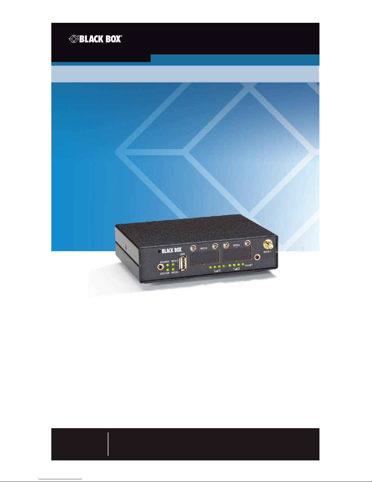
WRT4000 Series Cellular Wireless Routers
Order toll-free in the U.S. : Call 877-877-BBOX (outside U.S. call 724-746-5500)
FREE technical support 24 hours a day, 7 days a week: Call 724-746-5500 or fax
724-746-0746 • Mailing address: Black Box Corporation, 1000 Park Drive, Lawrence,
PA 15055-1018 • Web site: www.blackbox.com • E-mail : info @blackbox.com
Customer
Support
Information
March 2009
codes codes
codes codes
codes codes
WRT4001A WRT4011A WRT4001A-DC WRT4000-DIN
WRT4002A WRT4012A WRT4002A-DC WRT4000-PM
WRT4003A WRT4013A WRT4003A-DC WRT4000-ANT
WRT4004A WRT4014A WRT4004A-DC WRT4000-ANT-KIT
Page 2

Page 2
724-746-5500 | blackbox.com
WRT4000 Series Cellular Wireless Router Quick Start Guide
STEP A: Collect the Items Needed for Installation
1A. Get everything out of the shipping box. It should contain:
• This Quick Installlation Guide
• WRT4000 Series Cellular Wireless Router
1
• DC connector set or AC power adapter
• Antennas included
2A. Get additional items required to install the WRT4000 Series Cellular Wireless Router.
You will need:
• Computer with Web-browsing software
2
• Ethernet cable
• Subscriber Identity Module (SIM)
3
• Cellular wireless network account
3
NOTES:
1
This quick installation guide assumes that there will be one embedded cellular module.
2
JavaScript must be enabled in the Web browser.
3
The embedded cellular module must have a cellular wireless network account and a Subscriber
Identity Module (SIM) for that account. Order each SIM from a cellular wireless network provider.
SIMs are not shipped with the Router.
STEP B: Ports on the WRT4000 Series Cellular Wireless Router Chassis
USB
Port
Industrial model: left slot: installed
card with (2) serial ports;
Commercial model: empty slots
LEDs for
Power and
Status
LEDs (not
used)
LEDs for signal
strength for
internal wireless
module
Main antenna port for
internal wireless module
Figure 1. Front panel.
Page 3

Page 3
724-746-5500 | blackbox.com
WRT4000 Series Cellular Wireless Router Quick Start Guide
Auxiliary antenna port
for internal wireless module
Port for AC power
adapter input
Ethernet WAN port (eth 0)
Ethernet LAN ports (eth 1)
Figure 2. WRT4000 Series Router back panel, AC power.
Auxiliary antenna port
for internal
wireless module
DC power connector
Ethernet WAN port (eth 0)
Ethernet LAN ports (eth 1) Port for AC power
adapter input
Figure 3. WRT4000 Series Router back panel, DC power.
STEP C: Install the SIMs
1C. Make sure the WRT4000 Series Cellular Wireless Router is not connected to a power
source. Then make sure no cables are connected to the router's ports.
2C. Place the router chassis on a flat, stable surface. Turn the chassis over so that it is
resting on its top.
3C. Remove the screws from the sides of the chassis, and lift the chassis shell off the
bottom of the chassis. Locate the SIM slot 3 socket's on the bottom of the motherboard.
4C. Swing a SIM slot 3 socket'ss hinged door open. Insert a SIM between the guides on
the SIM socket‘s door, and slide the SIM into place.
Contact pad on back of SIM Contact pads on bottom plate of SIM socket
Figure 4. SIM partially inserted into the SIM socket‘s door.
5C. Gently close the SIM socket‘s door.
Page 4

Page 4
724-746-5500 | blackbox.com
WRT4000 Series Cellular Wireless Router Quick Start Guide
CAUTION: If the SIM is not in the correct position, the SIM socket‘s door will not close. In
that case, remove the SIM and re-insert it in the correct position.
If the SIM is positioned
incorrectly, the SIM socket’s
door will not close
If the SIM is positioned
correc tly, the SIM socket’s
door can close
Figure 5. SIM in an incorrect position. Figure 6. SIM in the correct position
6C. Re-assemble the router chassis. Attach antennas to the antenna ports on the chassis‘
front and back panels.
NOTE: The antenna ports labeled MAIN 1 (on the front panel) and AUX 1 (on the back
panel) hold antennas for the embedded module.
STEP D: Connect and Start the WRT4000 Series Cellular Wireless Router
1D. Connect an Ethernet cable between the computer‘s Ethernet port and one of the
Local Area Network ports (the set of LAN ports labeled “eth 1” on the back of the
router.
2D. To connect safely to DC power, follow the instructions in STEP E. To use only AC
power, connect the AC power adapter to the router chassis, then to an AC outlet.
(The chassis powers up immediately upon connection.) Then go to STEP F.
STEP E: Quick Connection to DC Power
For WRT4000 Series Cellular Wireless Routers that use DC power (part numbers
WRT4001A-DC, WRT4002A-DC, WRT4003A-DC, and WRT4004A-DC), the DC mating
connector is supplied. To connect your router to a power source, follow these instructions:
1E. Verify that the intended DC power source is the same as the input DC power indicated
on the unit. The routers have 24-VDC input voltage,
12V 1.2A
— — —
− +
Figure 7.12-VDC power input socket.
2E. Note the following (with connector orientation as shown):
Page 5

Page 5
724-746-5500 | blackbox.com
WRT4000 Series Cellular Wireless Router Quick Start Guide
• The right position is + (for the positive wire).
• The left position is - (for the negative/return wire).
− negativ
e
+ positive
- negative
+ positive
Figure 8. DC power connector with wires.
3E. Use a minimum 16 AWG wire with strip length of 0.27" (7 mm) to connect to each
position.
4E. Install a cable tie through the holes on the bottom of the shell assembly and around
the power cables, as shown.
5E. Install the snap-on cover, and plug the DC power connector assembly into the DC
power socket on the back of the router chassis.
Figure 9. Top section of shell above cabled lower shell assembly.
6E. If an AC adapter is also used to power the router, plug the AC barrel connector into
the mating socket labeled +5V.
Page 6

Page 6
724-746-5500 | blackbox.com
WRT4000 Series Cellular Wireless Router Quick Start Guide
STEP F: Login to the WRT4000 Series Cellular Wireless Router
1F. On the computer, open a Web browser. In the browser‘s address field, type the
router‘s default LAN IP address (192.168.1.1) and press the Enter key. Accept cookies for
the WRT4000 Series Cellular Wireless Router management system.
2F. When the browser displays the WRT4000 Series Cellular Wireless Router system login
screen, type the default user name (root) and password (blackbox!1). Then press the
Enter key or click the screen‘s button to Log In (at the far right, below the entry fields).
Figure 10. WRT4000 Series Cellular Wireless Router system login screen.
STEP G: Activate the Modules on the Cellular Networks
1G. If the SIM package did not include instructions, go to STEP 5G.
2G. If the SIM package included instructions to configure the Access Point Name (APN),
select the “Network” tab, then the “Interfaces” tab.
3G. On the Interface Overview screen, identify the row for the cellular wireless module,
and select the Edit button near the right side of the module‘s row.
4G. On the module‘s Interface Configuration Screen, select the correct Protocol and
Service Type; then type the APN as shown on the SIM package. Leave the other fields
as they are.
5G. Leave the chassis powered up for 30 minutes to allow automatic over-the-air (OTA)
activation to occur.
STEP H: Log Out of the WRT4000 Series Cellular Wireless Router
To close the WRT4000 Series Cellular Wireless Router management session, select the tab
to “Log Out.”
NOTE: If the management system is unattended for several minutes, the session will log
out automatically. To resume management, log in again.
Page 7

Page 7
724-746-5500 | blackbox.com
NOTES
Page 8

Black Box Tech Support: FREE! Live. 24/7.
Tech support the
way it should be.
Great tech support is just 60 seconds away at
724-746-5500 or blackbox.com.
724-746-5500 | blackbox.com
About Black Box
Black Box provides an extensive range of networking and infrastructure products.
You’ll find everything from cabinets and racks and power and surge protection
products to media converters and Ethernet switches all supported by free, live 24/7
Tech support available in 60 seconds or less.
© Copyright 2014. Black Box Corporation. All rights reserved. Black Box® and the Double Diamond logo
are registered trademarks of BB Technologies, Inc. Any third-party trademarks appearing in this manual
are acknowledged to be the property of their respective owners.
WRT4000-Series-Cellular-Wireless-Routers-Quick-Start-Guide, version 1
 Loading...