

Page 1

USER MANUAL
VX-HDMI-HDIP-TX, VX-HDMI-HDIP-RX
MEDIACENTO
IPX HD
24/7 TECHNICAL SUPPORT AT 1.877.877.2269 OR VISIT BLACKBOX.COM
4
3
5
2
6
1
7
0
8
F
9
E
A
D
B
Power
Link
B1
C
B2
Video
Channel
MEDIACENTO IPX HD
TRANSMITTER
Power
4
3
5
2
6
1
7
0
8
F
9
E
A
D
B
Link
B1
C
B2
Video
Channel
MEDIACENTO IPX HD
RECEIVER
Page 2

NEED HELP?
LEAV E TH E TEC H TO US
LIVE 24/7
TABLE OF CONTENTS
TECHNICAL
SUPPORT
1. 8 7 7. 8 7 7. 2 2 69
1. SPECIFICATIONS ........................................................................................................................................................................... 4
2. OVERVIE W ...................................................................................................................................................................................... 6
2.1 Introduction ...............................................................................................................................................................................................6
2.2 Features .................................................................................................................................................................................................... 6
2.3 What’s Included ........................................................................................................................................................................................7
2.4 Hardware Description ..............................................................................................................................................................................8
2.4.1 Transmitter ..........................................................................................................................................................................................................8
2.4.2 Receiver..............................................................................................................................................................................................................10
3. CONNECTIONS ............................................................................................................................................................................ 11
3.1 Point-to-Point Extension ........................................................................................................................................................................ 11
3.2 Broadcast/Cascade/Matrix Extension................................................................................................................................................. 11
4. NETWORK SETUP AND HARDWARE SWITCHING ................................................................................................................... 12
5. HARDWARE OPERATION ............................................................................................................................................................ 15
5.1 Button Switching for Unicast Mode ...................................................................................................................................................... 15
5.2 Button Switching for Multicast Mode ..................................................................................................................................................16
6. ACCESS TO WEB UI ..................................................................................................................................................................... 18
7. OPERATION FOR WEB UI ............................................................................................................................................................ 21
7.1 Configuring IP Mode ............................................................................................................................................................................... 21
7.2 Casting Mode for Extension Application ..............................................................................................................................................22
7.2.1 How to Change to Unicast Mode ...................................................................................................................................................................22
7.2.2 How to Change to Multicast Mode ...............................................................................................................................................................23
7.3 Output Video Scaling in Receiver ..........................................................................................................................................................24
7.4 Last Image Output Time for Source Content Lost ..............................................................................................................................25
7.5 Video Wall ................................................................................................................................................................................................ 25
8. ADVANCED SETUP ...................................................................................................................................................................... 33
2
1. 87 7. 8 7 7. 2 26 9 BL ACK BOX .COM
Page 3

NEED HELP?
LEAV E TH E TEC H TO US
LIVE 24/7
TABLE OF CONTENTS
TECHNICAL
SUPPORT
1. 8 7 7. 8 7 7. 2 2 69
APPENDIX A. REGULATORY INFORMATION ................................................................................................................................ 43
A.1 CE and RoHS2 ........................................................................................................................................................................................43
A.2 NOM Statement .................................................................................................................................................................................... 44
APPENDIX B. DISCLAIMER/TRADEMARKS ................................................................................................................................. 45
B.1 Disclaimer ............................................................................................................................................................................................... 45
B.2 Trademarks Used in this Manual ............................................................................................................ ..............................................45
1. 87 7. 8 7 7. 2 26 9 BL ACK BOX .COM
3
Page 4

CHAPTER 1: SPECIFICATIONS
TABLE 1-1. SPECIFICATIONS
SPECIFICATION DESCRIPTION
Connectors
Transmitter
Receiver
Audio Support
Transmitter and Receiver
User Controls
Hardware Switches
Indicators
Transmitter
Receiver
Video Input: (1) HDMI female
Network Port: RJ-45 Ethernet
Video Output: (1) HDMI female
Network Port: RJ-45 Ethernet
Supports high-definition audio (HD) 5.1/6.1/7.1 surround sound:
Dolby TrueHD, DTS-HD Master Audio
LPCM channels up to 7.1 channels 192 kHz
B1: Set/Reset Pushbutton
B2: Function Selection Pushbutton
Rotary switch: Select from 16 Video Channels (HEX 0–F), Paired TX and RX units must use the same channel
Status LEDs: Power (blue), Link (blue)
Function Selection LEDs:
EDID Update (blue)
Video Profile Selection (Video or graphic mode) (blue)
Status LEDs: Power (blue), Link (blue)
Function Selection LEDs:
EDID Update (blue)
Video Profile Selection (Video or graphic mode) (blue)
NEED HELP?
LEAV E TH E TEC H TO US
LIVE 24/7
TECHNICAL
SUPPORT
1. 8 7 7. 8 7 7. 2 2 69
4
1. 87 7. 8 7 7. 2 26 9 BL ACK BOX .COM
Page 5

CHAPTER 1: SPECIFICATIONS
TABLE 1-1 (CONTINUED). SPECIFICATIONS
SPECIFICATION DESCRIPTION
Additonal Specs
DDC Supported DDC, DDC2, DDC2B
Extension Cable Type and Length Ethernet, CAT5e/6 up to 328 ft. (100 m)
Maximum Video Resolution 1080p
Power
Power Supply Each unit: (1) External 5 VDC, 3 A
Complies with IEEE 802.3at standard, Class 4;
Power over Ethernet (PoE)
Environmental
Operating Temperature 32 to 122° F (0 to 50° C)
Storage Temperature -4 to +140° F (-20 to +60° C)
Humidity 0 to 80% relative humidity
Mechanical
Dimensions Each unit: 1.26” H x 3.86” W x 7.09” D (3.2 x 9.8 x 18 cm)
Weight Each unit: 1.04 lb. (0.47 kg)
Housing Material Metal Chassis
Power: Normal input: 48 VDC;
Input Range: 36 to 57 VDC;
Consumption: 10.5 W, CAT6, 328 ft. (100 m)
NEED HELP?
LEAV E TH E TEC H TO US
LIVE 24/7
TECHNICAL
SUPPORT
1. 8 7 7. 8 7 7. 2 2 69
1. 87 7. 8 7 7. 2 26 9 BL ACK BOX .COM
5
Page 6

NEED HELP?
LEAV E TH E TEC H TO US
LIVE 24/7
CHAPTER 2: OVERVIEW
2.1 INTRODUCTION
The MediaCento IPX HD extends HDMI over IP via CATx cable. The transmitters and receivers support multicasting. They can be
connected in a crosspoint matrix architecture. A built-in Web-UI is included for convenient operation.
TECHNICAL
SUPPORT
1. 8 7 7. 8 7 7. 2 2 69
2.2 FEATURES
• Requires only one UTP/STP CAT5e/6 cable
• Uses a visually lossless compression algorithm
• Extends HDMI Digital Audio/Videoup to 330 feet (100 meters) between Transmitter and Receiver (point-to-point)
• Supports Full HD 1080p video
• Supports all 3D image formats
• Allows video to be repeated or distributed in a point-to-point or a matrix application through a Gigabit Ethernet switch.
• Maps different Transmitter sources to channels and allows each Receiver to be assigned to a corresponding video channel
• Mounts on the wall or in a rack
• Supports Interlaced and Progressive Display Modes
•Features DDC, Hot-Plug Detection (HPD) and HDCP
• Uses Default EDID and EDID copy function for optimal PC-to-Screen performance
• Works as a Powered Device (PD) of Power over Ethernet (PoE)
• Use the rotary switch to select 16 video channels (HEX 0–F) for link routing
6
1. 87 7. 8 7 7. 2 26 9 BL ACK BOX .COM
Page 7

NEED HELP?
LEAV E TH E TEC H TO US
LIVE 24/7
CHAPTER 2: OVERVIEW
TECHNICAL
SUPPORT
1. 8 7 7. 8 7 7. 2 2 69
2.3 WHAT’S INCLUDED
Your package should include the following items. If anything is missing or damaged, contact Black Box Technical Support
at 877-877-2269 or info@blackbox.com
MediaCento IPX HD Transmitter (VX-HDMI-HDIP-TX) includes:
(1) MediaCento IPX HD Transmitter
(1) 5-VDC, 3-A power supply
(1) Quick Start Guide
MediaCento IPX HD Receiver (VX-HDMI-HDIP-RX) includes:
(1) MediaCento IPX HD Receiver
(1) 5-VDC, 3-A power supply
(1) Quick Start Guide
1. 87 7. 8 7 7. 2 26 9 BL ACK BOX .COM
7
Page 8
CHAPTER 2: OVERVIEW
2.4 HARDWARE DESCRIPTION
The MediaCento IPX 4K consists of a Transmitter unit and a Receiver unit.
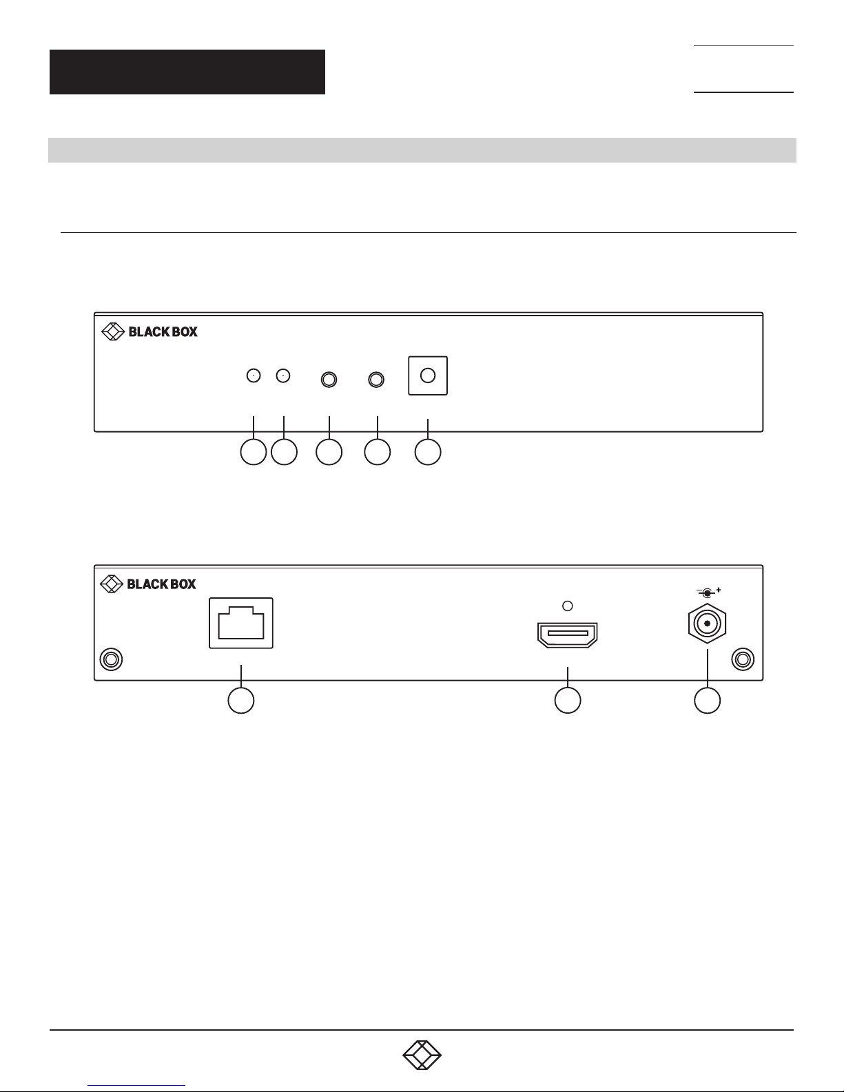
2.4.1 TRANSMITTER
Figures 2-1 and 2-2 show the front and back panels of the transmitter. Table 2-1 describes its components.
NEED HELP?
LEAV E TH E TEC H TO US
LIVE 24/7
TECHNICAL
SUPPORT
1. 8 7 7. 8 7 7. 2 2 69
Power
LAN
PoE
6
Link B1
1
B2
2
Video
Channel
43
5
FIGURE 2-1. TRANSMITTER FRONT PANEL
FIGURE 2-2. TRANSMITTER BACK PANEL
MEDIACENTO IPX HD
TRANSMITTER
HDMI In
7 8
DC 5V-3A
8
1. 87 7. 8 7 7. 2 26 9 BL ACK BOX .COM
Page 9

CHAPTER 2: OVERVIEW
TABLE 2-1. TRANSMITTER COMPONENTS
NEED HELP?
LEAV E TH E TEC H TO US
LIVE 24/7
TECHNICAL
SUPPORT
1. 8 7 7. 8 7 7. 2 2 69
NUMBER IN
FI GURE 2-1 OR 2-2
1 Power On status LED Lights steady when power on sequence is completed
2 Link LED for LAN link status
3 B1: Set/Reset button
4 B2: Function/Select button
5 Rotary Switch Use to set video channel
6 RJ-45 connector Used for LAN Link between transmitter and receiver/Gigabit Ethernet switch
7 HDMI In connector Connects to HDMI source for the source signal of HDMI extension over IP
8 5-VDC jack Links to 5-VDC power supply
COMPONENT DESCRIPTION
• Goes out when LAN link between Transmitter and Receiver/Gigabit Ethernet Switch is off
• Blinks when LAN link between Transmitter and Receiver/Gigabit Ethernet Switch is on
and there is no image data stream on the LAN link
• Lights steady ON when LAN link between Transmitter and Receiver/Gigabit Ethernet
Switch is on and there is an image data stream on the LAN link
Press to set a function, reset system, or reset to default
• Short press for setting the following functions
- EDID: Update EDID stored in Transmitter with EDID of display connecting to Transmitter
- Video Profile: Configure video profile with video or graphic mode
- Video Channel: Select video channel
• Long press (3 sec) for System Reset when no above functions selected to be set
• Longer press (6 sec) for Reset to Default when no above functions selected to be set
Select EDID, video profile, or video channel
• Press to cycle through setting EDID / Video Profile / Video Channel / Quit “Select” in
sequence
• Slow blink in the related LEDs when selecting EDID or Video Profile
• Slow blink in 7-segment LED display when selecting Video Channel
• Lights steady ON EDID LED indicator, Video Profile LED indicator and 7-segment LED
display when quitting “Select”
1. 87 7. 8 7 7. 2 26 9 BL ACK BOX .COM
9
Page 10
CHAPTER 2: OVERVIEW
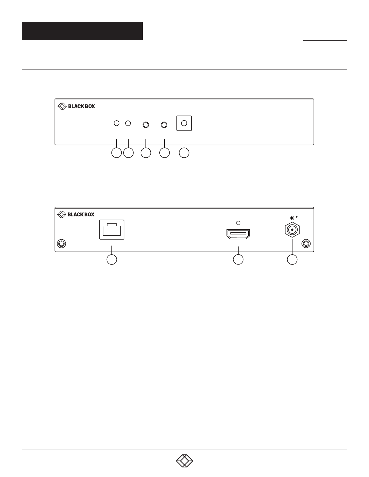
2.4.2 RECEIVER
Figures 2-3 and 2-4 show the front and back panels of the receiver. Table 2-2 describes its components.
NEED HELP?
LEAV E TH E TEC H TO US
LIVE 24/7
TECHNICAL
SUPPORT
1. 8 7 7. 8 7 7. 2 2 69
Power
1
Link B1
2
B2
Video
Channel
43
5
FIGURE 2-3. RECEIVER FRONT PANEL
LAN
PoE
6 87
FIGURE 2-4. RECEIVER BACK PANEL
HDMI Out
MEDIACENTO IPX HD
RECEIVER
DC 5V-3A
10
1. 87 7. 8 7 7. 2 26 9 BL ACK BOX .COM
Page 11

CHAPTER 2: OVERVIEW
TABLE 2-2. RECEIVER COMPONENTS
NEED HELP?
LEAV E TH E TEC H TO US
LIVE 24/7
TECHNICAL
SUPPORT
1. 8 7 7. 8 7 7. 2 2 69
NUMBER IN
FI GURE 2-3 OR 2-4
1 Power On status LED Lights steady when power on sequence is completed
2 Link LED for LAN link status
3 B1: Set/Reset button
4 B2: Function/Select button
5 Rotary Switch Use to set video channel
6 RJ-45 connector Used for LAN Link between transmitter and receiver/Gigabit Ethernet switch
7 HDMI Out connector Connects to HDMI source for the sink signal of HDMI extension over IP
8 5-VDC jack Links to 5-VDC power supply
COMPONENT DESCRIPTION
• Goes out when LAN link between Transmitter and Receiver/Gigabit Ethernet Switch is off
• Blinks when LAN link between Transmitter and Receiver/Gigabit Ethernet Switch is on
and there is no image data stream on the LAN link
• Lights steady ON when LAN link between Transmitter and Receiver/Gigabit Ethernet
Switch is on and there is an image data stream on the LAN link
Press to set a function, reset system, or reset to default
• Short press for setting the following functions
- EDID: Update EDID stored in Transmitter with EDID of display connecting to Receiver
- USB: Link or unlink USB extension
- Video Profile: Configure video profile with video or graphic mode
- Video Channel: Select video channel
• Long press (3 sec) for System Reset when no above functions selected to be set
• Longer press (6 sec) for Reset to Default when no above functions selected to be set
Select EDID, video profile, or video channel
• Press to cycle through setting EDID / Video Profile / Video Channel / Quit “Select” in
sequence
• Slow blink in the related LEDs when selecting EDID or Video Profile
• Slow blink in 7-segment LED display when selecting Video Channel
• Lights steady ON EDID LED indicator, Video Profile LED indicator and 7-segment LED
display when quitting “Select”
1. 87 7. 8 7 7. 2 26 9 BL ACK BOX .COM
11
Page 12
CHAPTER 3: CONNECTIONS
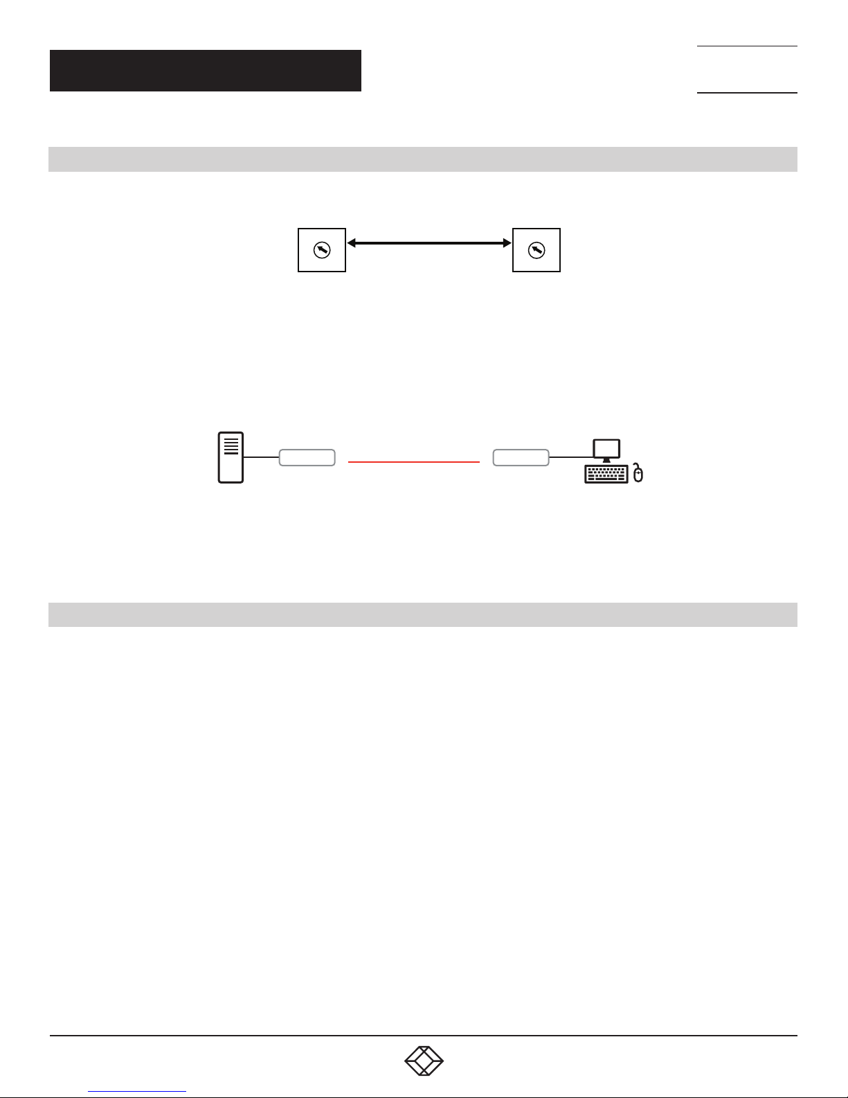
3.1 POINT-TO-POINT EXTENSION
NEED HELP?
LEAV E TH E TEC H TO US
LIVE 24/7
TECHNICAL
SUPPORT
1. 8 7 7. 8 7 7. 2 2 69
TX
4
5
3
6
2
7
1
8
0
9
F
A
E
B
D
C
RX
4
5
3
6
2
7
1
8
0
9
F
A
E
B
D
C
FIGURE 3-1. ROTARY SWITCH
For point-to-point extension, the TX and RX must be on the same video channel (16 channels ranging from 0 to F on the rotary
switch).
SOURCE
TX
CATX UTP/STP CABLE
RX
CONSOLE
NOTE: Copper cable is required
and can be point-to-point
or over an Ethernet network.
FIGURE 3-2. POINT-TO-POINT INSTALLATION
3.2 BROADCAST/CASCADE/MATRIX EXTENSION
For broadcast, cascade or matrix extension installations, you will need a Gigabit switch that supports IGMP V2 query and Jumbo Frame
(at least 8K).
Each TX must be set to a unique video channel (one of 16 channels) ranging from 0 to F (HEX) via its rotary switch. Set each RX video
channel to the channel that corresponds to the TX video channel. For larger installations, additional channels can be set via the CLI.
12
1. 87 7. 8 7 7. 2 26 9 BL ACK BOX .COM
Page 13

CHAPTER 3: CONNECTIONS
NEED HELP?
LEAV E TH E TEC H TO US
LIVE 24/7
TECHNICAL
SUPPORT
1. 8 7 7. 8 7 7. 2 2 69
01
4
5
3
6
2
7
1
8
0
9
F
A
E
B
D
C
Power
Ethernet
Gigabit Switch
Link B1B2Video
02
4
5
3
6
2
7
1
8
0
9
F
A
E
B
D
C
MEDIACENTO IPX 2K
RECEIVER
Channel
Link B1B2Video
Power
Channel
TX1
Ethernet
Gigabit Switch
01
4
5
3
6
2
7
1
8
0
9
SFP
10G SFP+
F
A
E
B
D
C
Link B1B2Video
Power
2526 2728
1
8
9
3
6
1011 12 13 1415 1617 1819 20
2
5
7
4
Channel
TX2
MEDIACENTO IPX 2K
RECEIVER
RX5
MEDIACENTO IPX 2K
RECEIVER
03
4
5
3
6
2
7
1
8
0
9
F
A
E
B
D
C
Power
SFP
1
8
9
3
6
1011 12 13 1415 1617 1819 20
2
5
7
4
Ethernet
Gigabit Switch
04
4
5
3
6
2
7
1
8
0
9
F
A
E
B
D
C
Power
Link B1B2Video
10G SFP+
2526 2728
Link B1B2Video
04
4
5
3
6
2
7
1
8
0
9
F
A
E
B
D
C
MEDIACENTO IPX 2K
RECEIVER
Channel
TX3
SFP
10G SFP+
1
Channel
2526 2728
8
9
3
6
1011 12 13 1415 1617 1819 20
2
5
7
4
MEDIACENTO IPX 2K
RECEIVER
Link B1B2Video
Power
02
4
5
3
6
2
7
1
8
0
9
F
A
E
B
D
C
Link B1B2Video
Power
MEDIACENTO IPX 2K
RECEIVER
Channel
TX4
MEDIACENTO IPX 2K
RECEIVER
Channel
RX7
RX6
CATx up to 328 ft. (100 m)
HDMI
03
4
5
3
6
2
7
1
8
0
9
F
A
E
B
D
C
Link B1B2Video
Power
MEDIACENTO IPX 2K
RECEIVER
Channel
RX1
03
4
5
3
6
2
7
1
8
0
9
F
A
E
B
D
C
Link B1B2Video
Power
MEDIACENTO IPX 2K
RECEIVER
Channel
RX2
03
3
2
1
0
F
E
FIGURE 3-3. BROADCAST/CASCADE/MATRIX EXTENSION APPLICATION
03
4
4
5
6
7
8
9
A
B
D
C
Link B1B2Video
Power
MEDIACENTO IPX 2K
RECEIVER
Channel
5
3
2
1
0
F
E
B
D
C
RX3 RX4
1. 87 7. 8 7 7. 2 26 9 BL ACK BOX .COM
6
7
8
9
A
Power
Link B1B2Video
MEDIACENTO IPX 2K
RECEIVER
Channel
13
Page 14

NEED HELP?
LEAV E TH E TEC H TO US
LIVE 24/7
CHAPTER 4: NETWORK SETUP AND HARDWARE SWITCHING
1. Power on the Gigabit Switch and enable Jumbo Frame (8K) and IGMP v2.
2. Using CAT5e/6 cables, connect all transmitters and receivers to the Gigabit Switch.
3. Using HDMI Cables, connect all transmitters to their video sources, and all receivers to their displays/TVs.
4. Plug in the DC power adapter to all TX and RX. The units will power on.
5. Power on all Video Sources and start playing video.
6. Power on all Displays/TVs and select HDMI input. The displays will show video from the selected video channel.
7. To set the video channel of the transmitter, rotate the rotary switch on the transmitter from 0 to F and then follow the steps below
to activate the setting.
7a. To unlink the transmitter, short-press the B1 button. The Link LED will go off.
7b. To link the transmitter, short-press B1 button until the Link LED blinks or constantly lights.
8. To connect to the different video channels (sources), change the receiver’s video channel by rotating the rotary switch to select the
video channel from channel 0 to F (HEX) and then follow the steps below to activate the connection.
8a. To unlink the receiver, short-press the B1 button. The Link LED will go off.
8b. To link the receiver, short-press B1 button until the Link LED blinks or constantly lights.
TECHNICAL
SUPPORT
1. 8 7 7. 8 7 7. 2 2 69
14
1. 87 7. 8 7 7. 2 26 9 BL ACK BOX .COM
Page 15

NEED HELP?
LEAV E TH E TEC H TO US
LIVE 24/7
CHAPTER 5: HARDWARE OPERATION
TECHNICAL
SUPPORT
1. 8 7 7. 8 7 7. 2 2 69
5.1 BUTTON SWITCHING FOR UNICAST MODE
Table 5-1 describes the button operation for unicast mode. The Items with asterisks (*) are described in Table 5-2.
TABLE 5-1. BUTTON OPERATION FOR UNICAST MODE
ACTION BUTTON 1 BUTTON 2
MEDIACENTO IPX HD TX
Short Press Link/Unlink Video Mode (default)/Graphic Mode*
Long Press (3 sec) N/A Anti-Dither 1/2 or OFF (default)
Long Press when Ethernet Link is Off N/A
Long Press on Boot (Press until Power LED Blinking) Engineering Mode* N/A
Long Press on Boot (Press until Power LED
and Link LED Blinking)
MEDIACENTO IPX HD RX
Short Press Link/Unlink Video Mode (default)/Graphic Mode*
Long Press (3 sec) N/A Anti-Dither 1/2 or OFF (default)
Engineering Mode and Reset to default* N/A
Long Press when Ethernet Link is Off N/A
Long Press on Boot (Press until Power LED Blinking) Engineering Mode* N/A
Long Press on Boot (Press until Power LED
and Link LED Blinking)
Engineering Mode and Reset to default* N/A
Ethernet Jumbo Frame ON (default) or OFF*
Ethernet Jumbo Frame ON (default) or OFF*
TABLE 5-2. BUTTON DESCRIPTIONS
STAT E /FE AT U RE DESCRIPTION
User can select to change between Video Mode/Graphic Mode using this button. The button state will be saved
to SPI flash, and will be retained after rebooting.
Video Mode/ Graphic Mode
Anti-Dither (1/2/off)
Engineering Mode
Reset to Default
Ethernet Jumbo Frame
• Video Mode: FW will automatically trade-off between bandwidth and video quality to ensure a smooth video
playing experience.
• Graphic Mode: Firmware will trade-off to ensure the best graphic/text viewing experience.
Anti-Dithering Mode is designed to work with graphic cards that provide dithering output. Dithering output
makes color looks better than its original color depth. It uses visual transients to create a half-tone effect. But
this reduces the ability of Video Compression to maintain low bandwidth even if the source display seems static.
This mode supports Anti-dithering for 1 bit, 2 bit, or off.
If the source content does not generate dithering output, and this feature is turned on, blocking may occur
because the Video Engine is unable to detect pixel changes. To avoid this, turn this Anti-Dither to off.
1. Static IP: 192.168.0.88
2. You can connect to http://192.168.0.88 webpage to update the firmware.
1. Reset Any changes in SPI flash setup flag.
2. After you Reset to Default, you MUST power cycle the device for the changes to take effect
1. Enable/Disable Ethernet jumbo frame.
2. If the link LED is ON solid, then jumbo frame is enabled. If link LED is blinking, then jumbo frame is disabled.
1. 87 7. 8 7 7. 2 26 9 BL ACK BOX .COM
15
Page 16

NEED HELP?
LEAV E TH E TEC H TO US
LIVE 24/7
CHAPTER 5: HARDWARE OPERATION
TECHNICAL
SUPPORT
1. 8 7 7. 8 7 7. 2 2 69
5.2 BUTTON SWITCHING FOR MULTICAST MODE
Table 5-3 describes the button operation for multicast mode. The Items with asterisks (*) are described in Table 5-4.
TABLE 5-3. BUTTON OPERATION FOR MULTICAST MODE
ACTION BUTTON 1 BUTTON 2
MEDIACENTO IPX HD TX
Short Press Link/Unlink Video Mode (default)/Graphic Mode*
Long Press (3 sec) N/A Anti-Dither 1/2 or OFF (default)
Long Press when Ethernet Link is Off N/A
Long Press on Boot (Press until Power LED Blinking) Engineering Mode* N/A
Long Press on Boot (Press until Power LED
and Link LED Blinking)
MEDIACENTO IPX HD RX
Short Press Link/Unlink Video Mode (default)/Graphic Mode*
Long Press (3 sec) N/A Anti-Dither 1/2 or OFF (default)
Engineering Mode and Reset to default* N/A
Long Press when Ethernet Link is Off N/A
Long Press on Boot (Press until Power LED Blinking) Engineering Mode* Update EDID*
Long Press on Boot (Press until Power LED
and Link LED Blinking)
Engineering Mode and Reset to default* N/A
Ethernet Jumbo Frame ON (default) or OFF*
Ethernet Jumbo Frame ON (default) or OFF*
16
1. 87 7. 8 7 7. 2 26 9 BL ACK BOX .COM
Page 17

CHAPTER 5: HARDWARE OPERATION
TABLE 5-4. BUTTON DESCRIPTIONS
STAT E /FE AT U RE DESCRIPTION
User can select to change between Video Mode/Graphic Mode using this button. The button state will be saved
to SPI flash, and will be retained after rebooting.
Video Mode/ Graphic Mode
Anti-Dither (1/2/off)
Update EDID
Engineering Mode
Reset to Default
Ethernet Jumbo Frame
• Video Mode: FW will automatically trade-off between bandwidth and video quality to ensure a smooth video
playing experience.
• Graphic Mode: Firmware will trade-off to ensure the best graphic/text viewing experience.
Anti-Dithering Mode is designed to work with graphic cards that provide dithering output. Dithering output
makes color looks better than its original color depth. It uses visual transients to create a half-tone effect. But
this reduces the ability of Video Compression to maintain low bandwidth even if the source display seems static.
This mode supports Anti-dithering for 1 bit, 2 bit, or off.
If the source content does not generate dithering output, and this feature is turned on, blocking may occur
because the Video Engine is unable to detect pixel changes. To avoid this, turn this Anti-Dither to off.
While in Multicast mode, a monitor/TV might have a lower resolution than the source. For example, you might
have one monitor/TV with 720p resolution but mostly 1080p. Select the monitor/TV with the lowest resolution
to ensure that all can be displayed correctly.
If you are using one pair of TX/RX in Matrix mode, you must update EDID correctly. If not, it will cause
compatibility issues.
Operation: Once the button event is triggered correctly at the client side, the system is setup correctly for
Multicast. The selected EDID will be updated to the Host Side EEPROM.
In the system setup, the last EDID updated will stay in the EEPROM. If users set up this button many times, the
last one triggered will be applied.
1. Static IP: 192.168.0.88
2. You can connect to http://192.168.0.88 webpage to update the firmware.
1. Reset Any changes in SPI flash setup flag.
2. After you Reset to Default, you MUST power cycle the device for the changes to take effect
1. Enable/Disable Ethernet jumbo frame.
2. If the link LED is ON solid, then jumbo frame is enabled. If link LED is blinking, then jumbo frame is disabled.
NEED HELP?
LEAV E TH E TEC H TO US
LIVE 24/7
TECHNICAL
SUPPORT
1. 8 7 7. 8 7 7. 2 2 69
1. 87 7. 8 7 7. 2 26 9 BL ACK BOX .COM
17
Page 18

NEED HELP?
LEAV E TH E TEC H TO US
LIVE 24/7
CHAPTER 6: ACCESS TO WEB UI
1. Power on the Gigabit Switch and enable Jumbo Frame and IGMP.
2. Connect all transmitters and receivers to the Gigabit Switch using CATx cable to set up the matrix extension network.
3. Using HDMI cables, connect all transmitters to video sources, and all receivers to displays/TVs/monitors.
4. To use the Web UI, you will need to connect a control PC to the Gigabit Switch using CATx cable.
5. If you are not using PoE power, plug in the DC power adapters to all transmitters and receivers. The units will power on.
6. Power on all Video Sources and start playing video.
7. To control the PC’s IP setting: Select Internet Protocol Version 4 (TCP/IPv4) - IP address: 169.254.2.1 or another IP address within
169.254.XXX.XXX - Netmask: 255.255.0.0
TECHNICAL
SUPPORT
1. 8 7 7. 8 7 7. 2 2 69
FIGURE 6-1. TCP/IPV4 GUI INTERFACE
8. To access the Web Interface Control Software:
8a. Select any receiver in the matrix extension network and unlink it by disconnecting its CATx cable.
8b. The OSD will immediately appear on the display connected to the selected receiver as follows. The selected receiver’s IP and
MAC address are shown in the OSD.
18
1. 87 7. 8 7 7. 2 26 9 BL ACK BOX .COM
Page 19

CHAPTER 6: ACCESS TO WEB UI
NEED HELP?
LEAV E TH E TEC H TO US
LIVE 24/7
TECHNICAL
SUPPORT
1. 8 7 7. 8 7 7. 2 2 69
Selected RX’s IP address
FIGURE 6-2. ON-SCREEN DISPLAY (OSD)
8c. Re-link the selected receiver to the matrix extension network by re-connecting the CATx cable.
8d. Access the Web browser via the control PC by using the selected receiver’s IP address shown in the OSD ( http://169.254.XXX.
XXX/ ).
1. 87 7. 8 7 7. 2 26 9 BL ACK BOX .COM
19
Page 20

CHAPTER 6: ACCESS TO WEB UI
8e. When the access is done, the home page of Web Interface Control Software will appear as follows.
NEED HELP?
LEAV E TH E TEC H TO US
LIVE 24/7
TECHNICAL
SUPPORT
1. 8 7 7. 8 7 7. 2 2 69
FIGURE 6-3. WEB INTERFACE CONTROL SOFTWARE HOME PAGE
20
1. 87 7. 8 7 7. 2 26 9 BL ACK BOX .COM
Page 21

NEED HELP?
LEAV E TH E TEC H TO US
LIVE 24/7
CHAPTER 7: OPERATION FOR WEB UI
7.1 CONFIGURING IP MODE
By default, the transmitter unit (TX) and the receiver unit (RX) are set to Auto IP Mode, automatically using IP addresses in the
169.254.xxx.xxx range with subnet mask 255.255.0.0. DHCP Mode and Static Mode can be selected for the related application. For
Static Mode, you do not need to change the IP address and subnet mask unless you know what IP address you can assign to this
device. To assign the static IP, all transmitters and receivers need to be in the same IP domain and corresponding subnet mask.
TECHNICAL
SUPPORT
1. 8 7 7. 8 7 7. 2 2 69
FIGURE 7-1. IP SETUP SCREEN
When you apply new settings, reboot the unit to take effect. To reboot the transmitter or receiver:
1. Power cycle the transmitter or receiver.
2. Click the Reboot button on the Web interface.
Reboot button
FIGURE 7-2. REBOOT BUTTON
1. 87 7. 8 7 7. 2 26 9 BL ACK BOX .COM
21
Page 22

NEED HELP?
LEAV E TH E TEC H TO US
LIVE 24/7
CHAPTER 7: OPERATION FOR WEB UI
7.2 CASTING MODE FOR EXTENSION APPLICATION
The Extension application has two casting modes: Multicast and Unicast. In Multicast mode, multiple Receiver (RX) units can
receive signals from multiple (or a single) Transmitter (TX) units(s) in the same network. In Unicast mode, only a single Receiver
(RX) unit can receive signals from a Transmitter (TX) unit with the same channel. By default, the Extension Application is
configured to Multicast Mode.
TECHNICAL
SUPPORT
1. 8 7 7. 8 7 7. 2 2 69
7.2.1 HOW TO CHANGE TO UNICAST MODE
1. By default, the Casting Mode of the TX and RX unit is Multicast Mode.
2. Click the Network tab, then click the Unicast button. When selected, the Unicast button will be highlighted in green, and then click
the Apply button.
When you apply new settings, reboot the unit to take effect. To reboot the TX unit or RX unit:
1. Press the “SET/RESET” button on the unit for 3 seconds.
OR
2. Click the Reboot button on the Web interface.
3. A message will be displayed, indicating that the casting mode has been applied to the TX unit.
22
FIGURE 7-3. CASTING MODE BUTTONS
FIGURE 7-4. CASTING MODE APPLIED MESSAGE
1. 87 7. 8 7 7. 2 26 9 BL ACK BOX .COM
Page 23

NEED HELP?
LEAV E TH E TEC H TO US
LIVE 24/7
CHAPTER 7: OPERATION FOR WEB UI
TECHNICAL
SUPPORT
1. 8 7 7. 8 7 7. 2 2 69
4. After a few seconds, another message will be displayed stating that the TX unit must be rebooted for the new setting to take
effect.
FIGURE 7-5. REBOOT MESSAGE
5. Reboot the TX unit by one of these methods:
• Power cycle the transmitter.
• Click the Reboot button on the Web interface.
6. Repeat steps 1 through 5 in sequence for each TX and RX on the network.
7.2.2 HOW TO CHANGE TO MULTICAST MODE
Click the Network tab and click the Multicast button. When selected, the Multicast button will be highlighted in green, and then click
the Apply button.
FIGURE 7-6. REBOOT BUTTON ON WEB UI
1. 87 7. 8 7 7. 2 26 9 BL ACK BOX .COM
23
Page 24

CHAPTER 7: OPERATION FOR WEB UI
NEED HELP?
LEAV E TH E TEC H TO US
LIVE 24/7
TECHNICAL
SUPPORT
1. 8 7 7. 8 7 7. 2 2 69
FIGURE 7-7. MULTICAST BUTTON
7.3 OUTPUT VIDEO SCALING IN RECEIVER
This function allows the specified receiver to scale its output video based on the resolution settings. The default setting is “Auto
Detect (Per EDID),” which means the receiver’s output video is automatically scaled up/down based on the EDID of the display
connecting to the receiver. “Pass-Through” mode means the receiver directly outputs the video without any scaling.
Select the needed setting and click “Apply” to activate it.
24
FIGURE 7-8. SCALER OUTPUT MODE SCREEN
1. 87 7. 8 7 7. 2 26 9 BL ACK BOX .COM
Page 25

NEED HELP?
LEAV E TH E TEC H TO US
LIVE 24/7
CHAPTER 7: OPERATION FOR WEB UI
TECHNICAL
SUPPORT
1. 8 7 7. 8 7 7. 2 2 69
7.4 LAST IMAGE OUTPUT TIME FOR SOURCE CONTENT LOST
When the transmitter’s source content is lost, the receiver’s video output will be frozen in the last image for a time period from 3
sec to 60 sec. Select the needed time and click “Apply” to activate it.
FIGURE 7-9. SELECT TIMEOUT SCREEN
7.5 VIDEO WALL
1. Set up a broadcast link of one transmitter and many receivers by using the Gigabit Switch (supporting IGMP, 8K jumbo frame)
with CATx cable.
2. Also connect a PC to the same Gigabit Switch with CATx cable. Set this PC’s IP domain and subnet mask to be 169.254.XXX.XXX
and 255.255.0.0.
3. Make sure to set the transmitter’s and receivers’ Casting Mode to Multicast mode (default setting is Multicast mode).
4. Click “Video Wall” Tab in Web UI of the transmitter or receiver unit, and the video wall control panel will appear.
1. 87 7. 8 7 7. 2 26 9 BL ACK BOX .COM
25
Page 26

CHAPTER 7: OPERATION FOR WEB UI
NEED HELP?
LEAV E TH E TEC H TO US
LIVE 24/7
TECHNICAL
SUPPORT
1. 8 7 7. 8 7 7. 2 2 69
26
FIGURE 7-10. VIDEO WALL SE TUP SCREEN
1. 87 7. 8 7 7. 2 26 9 BL ACK BOX .COM
Page 27

NEED HELP?
LEAV E TH E TEC H TO US
LIVE 24/7
CHAPTER 7: OPERATION FOR WEB UI
5. Follow these steps for set up the video wall:
STEP 1: Set common values of all devices.
1a. Set bezel and gap compensation:
• This step is used to configure the bezel and gap compensation. If user doesn’t need this, just set all values to 0.
• Follow the picture and input the size of the monitor used. Note that is unit is 0.1 mm and the value MUST be an integer.
TECHNICAL
SUPPORT
1. 8 7 7. 8 7 7. 2 2 69
FIGURE 7-11. SET BEZEL AND GAP COMPENSATION
1. 87 7. 8 7 7. 2 26 9 BL ACK BOX .COM
27
Page 28

CHAPTER 7: OPERATION FOR WEB UI
1b. Set Wall Size:
• Set “Vertical Monitor Count” from 1 to 8 based on the real application
• Set “Horizontal Monitor Count” from 1 to 16 based on the real application
NEED HELP?
LEAV E TH E TEC H TO US
LIVE 24/7
TECHNICAL
SUPPORT
1. 8 7 7. 8 7 7. 2 2 69
28
FIGURE 7-12. SET WALL SIZE
1. 87 7. 8 7 7. 2 26 9 BL ACK BOX .COM
Page 29

CHAPTER 7: OPERATION FOR WEB UI
1c. Select “All” in “Apply To” list and press the “Apply” button.
FIGURE 7-13. SELECT ALL AND PRESS APPLY BUT TON
• The video wall layout will be refreshed accordingly.
STEP 2: Set up the row and column position for each display attached to receivers.
2a. Check “Show OSD” to show the index number on each receiver’s display to identify each receiver.
NEED HELP?
LEAV E TH E TEC H TO US
LIVE 24/7
TECHNICAL
SUPPORT
1. 8 7 7. 8 7 7. 2 2 69
FIGURE 7-14. SHOW OSD BUTTON
2b. Go through all client (receiver) devices (in the “Apply To” list) one by one and set the corresponding “Row Position” (0–7) and
“Column Position” (0–15), then click “Apply.”
1. 87 7. 8 7 7. 2 26 9 BL ACK BOX .COM
29
Page 30

CHAPTER 7: OPERATION FOR WEB UI
NEED HELP?
LEAV E TH E TEC H TO US
LIVE 24/7
TECHNICAL
SUPPORT
1. 8 7 7. 8 7 7. 2 2 69
FIGURE 7-15.
30
1. 87 7. 8 7 7. 2 26 9 BL ACK BOX .COM
Page 31

CHAPTER 7: OPERATION FOR WEB UI
NEED HELP?
LEAV E TH E TEC H TO US
LIVE 24/7
TECHNICAL
SUPPORT
1. 8 7 7. 8 7 7. 2 2 69
FIGURE 7-16.
1. 87 7. 8 7 7. 2 26 9 BL ACK BOX .COM
31
Page 32

CHAPTER 7: OPERATION FOR WEB UI
2c. Un-check “Show OSD” when completed.
STEP 3: Basic Video Wall setup is completed
NEED HELP?
LEAV E TH E TEC H TO US
LIVE 24/7
TECHNICAL
SUPPORT
1. 8 7 7. 8 7 7. 2 2 69
32
FIGURE 7-17.
1. 87 7. 8 7 7. 2 26 9 BL ACK BOX .COM
Page 33

NEED HELP?
LEAV E TH E TEC H TO US
LIVE 24/7
CHAPTER 8: ADVANCED SETUP
TECHNICAL
SUPPORT
1. 8 7 7. 8 7 7. 2 2 69
The Advanced Setup in the web UI is used to perform special effects that are not included in Basic Setup. For most cases,
Advanced Setup is never used. There are two steps in advanced setup:
Step 1: Choose the target(s) to apply the setup to.
Step 2: Apply setup.
From Step 1, user can choose one or more targets to apply the changes to. After the targets are selected, changes can be applied
in Step 2.
FIGURE 8-1. ADVANCED SETUP SCREEN
1. 87 7. 8 7 7. 2 26 9 BL ACK BOX .COM
33
Page 34

CHAPTER 8: ADVANCED SETUP
Following is the explanation of Step 2:
Reset to Basic Setup
- Reset the target to the setting of “Basic Setup”
- Apply to: host (TX), client (RX)
Stretc h Type
- Fit In: Try to stretch the full screen to the whole wall.
- Stretch Out: Keep the picture aspect ratio and stretch out the screen if needed.
Apply to: client (RX)
Rotate Clockwise:
- 0: No rotate
-180: rotate clockwise 180 degree
- 270: rotate clockwise 270 degree
Screen Layout (Row x Column)
- Change the screen layout
- Apply to: host (TX), client (RX)
Row Position
- Change the row position of the target
- Apply to: host (TX), client (RX)
Column Position
- Change the column position of target 28
Apply to: client (RX)
Horizontal Shift
- Horizontal shift target screen to left or right
Apply to:
- Client (RX)
- Shift unit: 1 pixel
NOTE: You can’t shift right when the screen touches the left edge.
NEED HELP?
LEAV E TH E TEC H TO US
LIVE 24/7
TECHNICAL
SUPPORT
1. 8 7 7. 8 7 7. 2 2 69
Vertical Shift
- Vertical shift target screen to up or down
- Apply to:
— host (TX): in 1 pixel unit
— client (RX): in 1 pixel unit
NOTE: You can’t shift down when the screen touches the top edge.
Horizontal Scale Up
- Horizontal scale up target
- Apply to: client (RX)
- Unit: (1/column count) pixel
34
1. 87 7. 8 7 7. 2 26 9 BL ACK BOX .COM
Page 35

CHAPTER 8: ADVANCED SETUP
Vertical Scale Up
- Vertical Scale up target
- Apply to: client (RX)
- Unit: (1/row count) pixel
Console API Command
- Used to fire a console command to a selected target.
- Apply to: host (TX), client (RX)
NEED HELP?
LEAV E TH E TEC H TO US
LIVE 24/7
TECHNICAL
SUPPORT
1. 8 7 7. 8 7 7. 2 2 69
1. 87 7. 8 7 7. 2 26 9 BL ACK BOX .COM
35
Page 36

APPENDIX A: REGULATORY INFORMATION
A.1 CE AND ROHS2
This product complies with CE and ROHS2 certifications.
NEED HELP?
LEAV E TH E TEC H TO US
LIVE 24/7
TECHNICAL
SUPPORT
1. 8 7 7. 8 7 7. 2 2 69
36
1. 87 7. 8 7 7. 2 26 9 BL ACK BOX .COM
Page 37

NEED HELP?
LEAV E TH E TEC H TO US
LIVE 24/7
APPENDIX A: REGULATORY INFORMATION
TECHNICAL
SUPPORT
1. 8 7 7. 8 7 7. 2 2 69
A.2 NOM STATEMENT
1. Todas las instrucciones de seguridad y operación deberán ser leídas antes de que el aparato eléctrico sea operado.
2. Las instrucciones de seguridad y operación deberán ser guardadas para referencia futura.
3. Todas las advertencias en el aparato eléctrico y en sus instrucciones de operación deben ser respetadas.
4. Todas las instrucciones de operación y uso deben ser seguidas.
5. El aparato eléctrico no deberá ser usado cerca del agua—por ejemplo, cerca de la tina de baño, lavabo, sótano mojado o cerca
de una alberca, etc.
6. El aparato eléctrico debe ser usado únicamente con carritos o pedestales que sean recomendados por el fabricante.
7. El aparato eléctrico debe ser montado a la pared o al techo sólo como sea recomendado por el fabricante.
8. Servicio—El usuario no debe intentar dar servicio al equipo eléctrico más allá a lo descrito en las instrucciones de operación.
Todo otro servicio deberá ser referido a personal de servicio calificado.
9. El aparato eléctrico debe ser situado de tal manera que su posición no interfiera su uso. La colocación del aparato eléctrico
sobre una cama, sofá, alfombra o superficie similar puede bloquea la ventilación, no se debe colocar en libreros o gabinetes que
impidan el flujo de aire por los orificios de ventilación.
10. El equipo eléctrico deber ser situado fuera del alcance de fuentes de calor como radiadores, registros de calor, estufas u otros
aparatos (incluyendo amplificadores) que producen calor.
11. El aparato eléctrico deberá ser connectado a una fuente de poder sólo del tipo descrito en el instructivo de operación, o como
se indique en el aparato.
12. Precaución debe ser tomada de tal manera que la tierra fisica y la polarización del equipo no sea eliminada.
13. Los cables de la fuente de poder deben ser guiados de tal manera que no sean pisados ni pellizcados por objetos colocados
sobre o contra ellos, poniendo particular atención a los contactos y receptáculos donde salen del aparato.
14. El equipo eléctrico debe ser limpiado únicamente de acuerdo a las recomendaciones del fabricante.
15. En caso de existir, una antena externa deberá ser localizada lejos de las lineas de energia.
16. El cable de corriente deberá ser desconectado del cuando el equipo no sea usado por un largo periodo de tiempo.
17. Cuidado debe ser tomado de tal manera que objectos liquidos no sean derramados sobre la cubierta u orificios de ventilación.
18. Servicio por personal calificado deberá ser provisto cuando:
A: El cable de poder o el contacto ha sido dañado; u
B: Objectos han caído o líquido ha sido derramado dentro del aparato;o
C: El aparato ha sido expuesto a la lluvia; o
D: El aparato parece no operar normalmente o muestra un cambio en su desempeño; o
E: El aparato ha sido tirado o su cubierta ha sido dañada.
1. 87 7. 8 7 7. 2 26 9 BL ACK BOX .COM
37
Page 38

NEED HELP?
LEAV E TH E TEC H TO US
LIVE 24/7
APPENDIX B: DISCLAIMER/TRADEMARKS
TECHNICAL
SUPPORT
1. 8 7 7. 8 7 7. 2 2 69
B.1 DISCLAIMER
Black Box Corporation shall not be liable for damages of any kind, including, but not limited to, punitive, consequential or cost of cover
damages, resulting from any errors in the product information or specifications set forth in this document and Black Box Corporation
may revise this document at any time without notice.
B.2 TRADEMARKS USED IN THIS MANUAL
Black Box and the Black Box logo type and mark are registered trademarks of Black Box Corporation.
Any other trademarks mentioned in this manual are acknowledged to be the property of the trademark owners.
38
1. 87 7. 8 7 7. 2 26 9 BL ACK BOX .COM
Page 39

NOTES
________________________________________________________________________________________________
__
________________________________________________________________________________________________
__
________________________________________________________________________________________________
__
________________________________________________________________________________________________
__
________________________________________________________________________________________________
__
NEED HELP?
LEAV E TH E TEC H TO US
LIVE 24/7
TECHNICAL
SUPPORT
1. 8 7 7. 8 7 7. 2 2 69
________________________________________________________________________________________________
__
________________________________________________________________________________________________
__
_
________________________________________________________________________________________________
_
________________________________________________________________________________________________
__
________________________________________________________________________________________________
_ _\
________________________________________________________________________________________________
__
________________________________________________________________________________________________
__
________________________________________________________________________________________________
__
1. 87 7. 8 7 7. 2 26 9 BL ACK BOX .COM
39
Page 40

NEED HELP?
LEAVE THE TECH TO US
LIVE 24/7
TECHNICAL
SUPPORT
1.877.877.2269
© COPYRIGHT 2018 BLACK BOX CORPORATION. ALL RIGHTS RESERVED.
VX-HDMI-HDIP-TX_RX_USER_R EV1.PDF
 Loading...