

Page 1
USER MANUAL
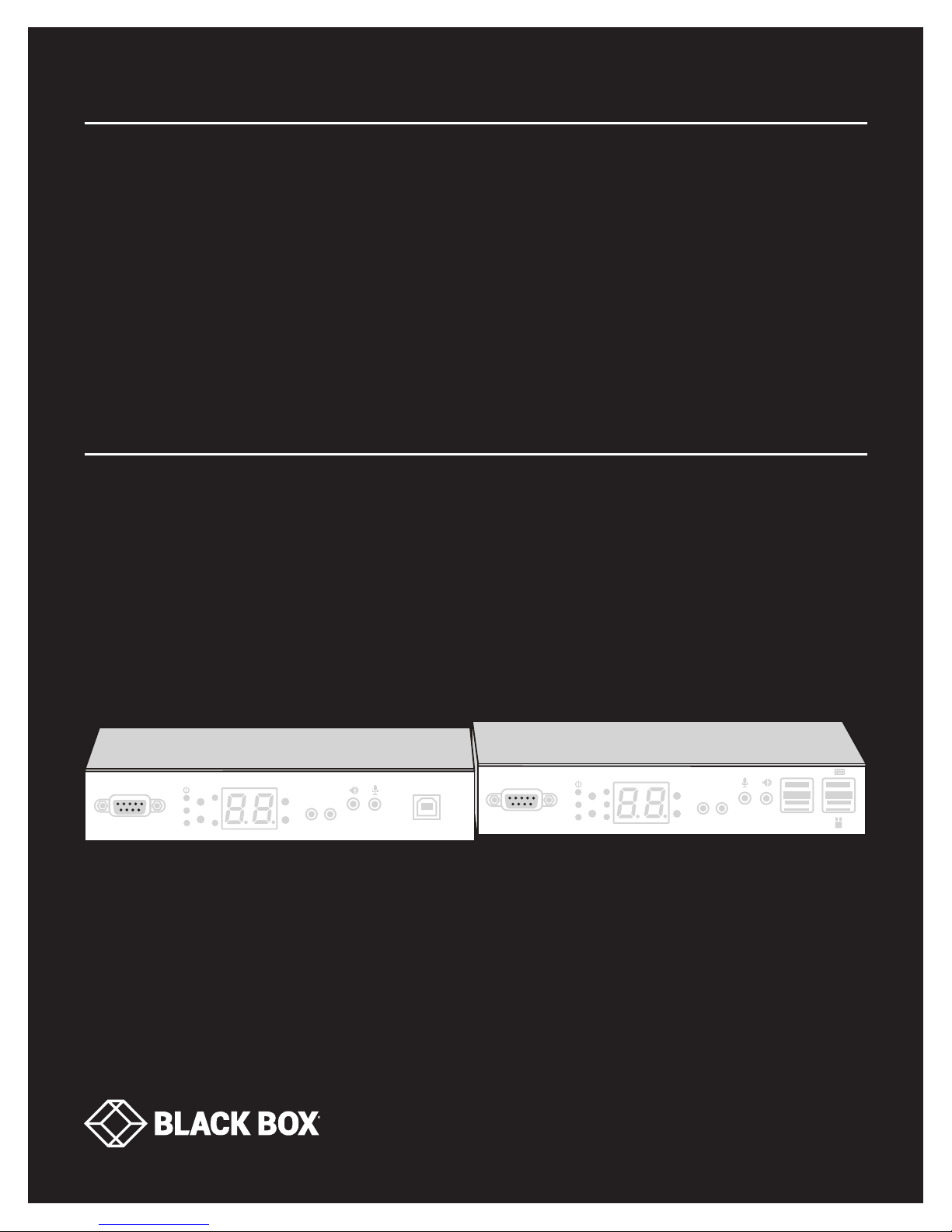
VX-HDMI-4KIP-TX, V X-HDMI-4KIP-RX
MEDIACENTO
IPX 4K
24/7 TECHNICAL SUPPORT AT 1.877.877.2269 OR VISIT BLACKBOX.COM
Serial over IP
Link
Video Channel
EDID
SET
RESET
Select
V.ProfileSFP
CH+
IR
Emitter
CH-
Receiver
IR
USB
Serial over IP
Link
SFP
Video Channel
EDID
SET
RESET
USB
Select
V.Profile
CH+
CH-
IR
IR
Receiver
Emitter
USB
Page 2

NEED HELP?
LEAV E TH E TEC H TO US
LIVE 24/7
TABLE OF CONTENTS
TECHNICAL
SUPPORT
1. 8 7 7. 8 7 7. 2 2 69
1. SPECIFICATIONS ........................................................................................................................................................................... 4
2. OVERVIE W ...................................................................................................................................................................................... 6
2.1 Introduction ...............................................................................................................................................................................................6
2.2 Features .................................................................................................................................................................................................... 6
2.2.1 Basic Features ....................................................................................................................................................................................................6
2.2.2 Advanced Features ............................................................................................................................................................................................ 7
2.3 What’s Included ........................................................................................................................................................................................7
2.4 Hardware Description ..............................................................................................................................................................................8
2.4.1 Transmitter ..........................................................................................................................................................................................................8
2.4.2 Receiver..............................................................................................................................................................................................................12
3. CONNECTIONS ............................................................................................................................................................................ 15
3.1 One-to-One Mapping Extension ............................................................................................................................................................ 15
3.2 Multicasting ............................................................................................................................................................................................ 15
4. NETWORK SETUP AND HARDWARE SWITCHING ................................................................................................................... 17
5. HARDWARE OPERATION ............................................................................................................................................................ 18
5.1 EDID Update by Buttons ......................................................................................................................................................................... 18
5.1.1 “EDID Update” for HDMI Sink Device on TX or RX Side ............................................................................................................................ 18
5.1.2 “EDID Update” to be Factory Default .............................................................................................................................................................18
5.2 Audio Over IP Extension ............................................................................................................ ............................................................18
5.3 Video Profile ........................................................................................................................................................................................... 19
5.4 Hotkey Video Channel Switch on RX Side ...........................................................................................................................................20
6. ACCESS TO WEB UI ..................................................................................................................................................................... 21
7. OPERATION FOR WEB UI ............................................................................................................................................................ 23
7.1 Configuring IP Mode ............................................................................................................................................................................... 23
7.2 Device Mode of Extension Application .................................................................................................................................................24
7.2.1 How to Change to Extender Mode ................................................................................................................................................................ 24
7.2.2 How to Change to Matrix Mode.....................................................................................................................................................................27
7.3 Jumbo Frame Requirement for the Link Between TX and RX ............................................................................................................28
7.4 Automatically Copy EDID of RX Display ...............................................................................................................................................29
7.5 Output Video Scaling in RX ....................................................................................................................................................................30
7.6 Last Image Output Time for Source Content Lost .............................................................................................................................. 31
7.7 Output Video Rotation in RX ..................................................................................................................................................................32
7.8 Serial (RS-232) Over IP Extension .........................................................................................................................................................33
7.9 USB Over IP Extension ...........................................................................................................................................................................35
7.10 Matrix Connection Management with Displaying TX’s Source Content ..........................................................................................35
7.11 Video Wall .............................................................................................................................................................................................. 37
2
1. 87 7.8 7 7. 2 26 9 BLACKBOX.COM
Page 3

NEED HELP?
LEAV E TH E TEC H TO US
LIVE 24/7
CHAPTER 1: HEADLINE
TECHNICAL
SUPPORT
1. 8 7 7. 8 7 7. 2 2 69
APPENDIX A. FIBER MODULES AND CABLES .............................................................................................................................. 42
APPENDIX B. REGULATORY INFORMATION ................................................................................................................................ 43
B.1 CE and RoHS2 ......................................................................................................................................................................................... 43
B.2 NOM Statement .................................................................................................................................................................................... 44
APPENDIX C. DISCLAIMER/TRADEMARKS ................................................................................................................................. 45
C.1 Disclaimer ............................................................................................................................................................................................... 45
C.2 Trademarks Used in this Manual .......................................................................................................................................................... 45
1. 87 7.8 7 7. 2 26 9 BLACKBOX.COM
3
Page 4

CHAPTER 1: SPECIFICATIONS
TABLE 1-1. SPECIFICATIONS
SPECIFICATION DESCRIPTION
Connectors
Video Output: (1) HDMI female
Serial Control Port (RS-232): (1) DB9 female
Video Input: (1) HDMI female
Transmitter
Receiver
Audio Support
Transmitter and Receiver
User Controls
Hardware Switches
Infrared Remote Bidirectional, through 20 to 60 kHz, two-way passthrough
Indicators
Transmitter
Receiver
Network Port: RJ-45 Ethernet
Audio + IR + RS-232 + USB Extension over IP)
Fiber Por t: SFP Ethernet
USB interface: (1) USB Type B female
Audio: 2-way analog audio, (1) Line IN, (1) Line OUT
Console Connection:
Video Output: (1) HDMI female
Serial Control Port (RS-232): (1) DB9 male
Network Port: RJ-45 Ethernet
Audio + IR + RS-232 + USB Extension over IP)
Fiber Por t: SFP Ethernet
USB interface: 2-way analog audio: (1) Mic IN, (1) Line OUT
Supports high-definition audio (HD) 5.1/6.1/7.1 surround sound:
Dolby TrueHD, DTS-HD Master Audio
LPCM channels up to 7.1 channels 192 kHz
Set/Reset: Pushbutton
Function Selection: Pushbutton
Video Channel: Pushbutton (CH+/CH-)
Status LEDs:
Power (blue), Link (blue)
Function Selection LEDs:
EDID Copy (blue)
SFP Status (blue)
Video Profile Selection (Video or graphic mode) (blue)
Status LEDs:
Power (blue), Link (blue)
Function Selection LEDs:
EDID Update (blue)
SFP Status (blue)
Video Profile Selection (Video or graphic mode) (blue)
USB Link (upstream) (blue)
NEED HELP?
LEAV E TH E TEC H TO US
LIVE 24/7
TECHNICAL
SUPPORT
1. 8 7 7. 8 7 7. 2 2 69
4
1. 87 7.8 7 7. 2 26 9 BLACKBOX.COM
Page 5

CHAPTER 1: SPECIFICATIONS
TABLE 1-1 (CONTINUED). SPECIFICATIONS
SPECIFICATION DESCRIPTION
Additonal Specs
DDC Supported DDC, DDC2, DDC2B
Extension Cable Type and Length
Maximum Video Resolution Up to 4096 x 2160 @ 30 Hz
Power
Power Supply (1) 5-VDC, 3-A power supply
Power over Ethernet (PoE)
Environmental
Operating Temperature 32 to 122° F (0 to 50° C)
Storage Temperature -4 to +140° F (-20 to +60° C)
Humidity 0 to 80% relative humidity
Mechanical
Dimensions 1.25"H x 3.58"W x 7.34"D (3.2 x 9.8 x 18 cm)
Weight
Housing Material Metal Chassis
Ethernet, CAT5e/6 up to 328 ft. (100 m)
Fiberoptic (SFP module), single-mode, up to 30 km
Complies with IEEE 802.3at standard, Class 4;
Power: Normal input: 48 VDC;
Input Range: 36 to 57 VDC;
Consumption: 10.5 W, CAT6, 328 ft. (100 m)
Transmitter: 1.034 lb. (470 g)
Receiver: 1.036 lb. (471 g)
NEED HELP?
LEAV E TH E TEC H TO US
LIVE 24/7
TECHNICAL
SUPPORT
1. 8 7 7. 8 7 7. 2 2 69
TABLE 1-2. COMPATIBLE SFPS
PART NUMBER DESCRIPTION
LFP411 SFP, 1250-Mbps Fiber with Extended Diagnostics, 850-nm Multimode, 550 m LC
LF P412 SFP, 1250-Mbps Fiber with Extended Diagnostics, 1310-nm Multimode, 2 km LC
LF P413 SFP, 1250-Mbps Fiber with Extended Diagnostics, 1310-nm Single-Mode, 10 km LC
LFP414 SFP, 1250-Mbps Fiber with Extended Diagnostics, 1310-nm Single-Mode, 30 km LC
LFP418 SFP, 1250-Mbps Fiber with Extended Diagnostics, 1550 -nm Single-Mode, 80 km, LC
NOTE:
Also should support most gigabit fiber SFP modules
1. 87 7.8 7 7. 2 26 9 BLACKBOX.COM
5
Page 6

NEED HELP?
LEAV E TH E TEC H TO US
LIVE 24/7
CHAPTER 2: OVERVIEW
2.1 INTRODUCTION
The MediaCento IPX 4K extends HDMI, USB, Audio, RS-232, and IR over IP via CATx or single-mode fiberoptic cable. The extender
consists of two units: one transmitter and one receiver.
NOTE: You can link the transmitter and receiver together via one CATx cable or one single-mode fiberoptic cable, but not both types of cable
at the same time.
Multicasting supports multiple transmitters (TX) and receivers (RX) that can be arranged in a crosspoint matrix architecture.
The extender supports 7.1 CH audio, 3D video, and USB 2.0/1.1.
You can use the built-in web user interface (UI) for configuration and operation.
2.2 FEATURES
TECHNICAL
SUPPORT
1. 8 7 7. 8 7 7. 2 2 69
2.2.1 BASIC FEATURES
Uses one UTP/STP CATx cable OR one single-mode fiberoptic cable between each transmitter/receiver link
Supports a visually lossless compression algorithm
Extends HDMI Digital Audio/Video up to 330 feet (100 meters) between Transmitter and Receiver (point-to-point) using CATx cable
or up to 6.2 miles (10 kilometers) between Transmitter and Receiver over single-mode fiberoptic cable using a standard SFP (Small
Form-factor Pluggable) module.
Compatible SFPs include Black Box part numbers LFP411, LFP412, LFP413, LFP414, and LFP418. Also should support most gigabit
fiber SFP modules
Supports Ultra HD video 4096 x 2160 @ 30 Hz and 1920 x 1200 @ 60 Hz (reduced blanking)
Supports all 3D image formats
Provides repeating/distributing/matrix extension through a Gigabit Ethernet Switch with a transceiver installed that is compatible
with both Transmitter and Receiver units and video wall
Compatible with USB 2.0 devices at data rates up to 480 Mbps and backward with USB 1.1. The transmitter uses one USB Type B
host interface and the receiver uses four USB Type A device interfaces.
Can map different transmitter sources or create a grouping loop for each receiver that corresponds to a video channel
Wall-mount housing design with rack mountable bracket enables easy and robust installation
Audio supports 7.1CH LPCM, DTS, Dolby, analog LINE-IN/LINE-OUT
Supports Interlaced and Progressive Display Modes
Provides DDC/DDC2B, Hot-Plug Detection (HPD) and complies with HDCP standards
Supports Default EDID and EDID copy function for optimal PC-to-Screen performance
Uses a bidirectional Infrared Remote (IR) signal and RS-232 control communication (Transmitter and Receiver)
Transmitter has a 4K HDMI local loopback output
Uses a 7-segment LED display for video channel indication
Includes IR remote control for video channel setting
Operates as a PoE powered device (PD) using IEEE 802.3at PoE+
6
1. 87 7.8 7 7. 2 26 9 BLACKBOX.COM
Page 7

NEED HELP?
LEAV E TH E TEC H TO US
LIVE 24/7
CHAPTER 2: OVERVIEW
TECHNICAL
SUPPORT
1. 8 7 7. 8 7 7. 2 2 69
2.2.2 ADVANCED FEATURES
Web UI shows the linking connection status for all Transmitter (TX) and Receiver (RX) units
Switches TX-RX connections via web UI, pushbuttons, IR remote control or keyboard hotkey
Can upgrade firmware via web UI
Visualizes video wall configuration
Transmitter (TX) unit monitors HDMI-in and synchronizes HDMI-out
If a firmware update fails, the MediaCento IPX 4K recovers redundant Flash ROM
Two-digit LED display indicates current transmitting and receiving channel
Supports 99 selectable channels to transmit or receive
2.3 WHAT’S INCLUDED
Your package should include the following items. If anything is missing or damaged, contact Black Box Technical Support
at 877-877-2269 or info@blackbox.com
MediaCento IPX 4K Transmitter (VX-HDMI-4KIP-TX) includes:
(1) MediaCento IPX 4K Transmitter
(1) 5-VDC, 3-A power supply
(1) IR blaster cable
(1) USB 2.0 cable
(1) Audio/mic cable
This user manual
MediaCento IPX 4K Receiver (VX-HDMI-4KIP-RX) includes:
(1) MediaCento IPX 4K Receiver
(1) 5-VDC, 3-A power supply
(1) IR receiver cable
(1) IR remote control
This user manual
1. 87 7.8 7 7. 2 26 9 BLACKBOX.COM
7
Page 8
CHAPTER 2: OVERVIEW
2.4 HARDWARE DESCRIPTION
The MediaCento IPX 4K consists of a Transmitter unit and a Receiver unit.
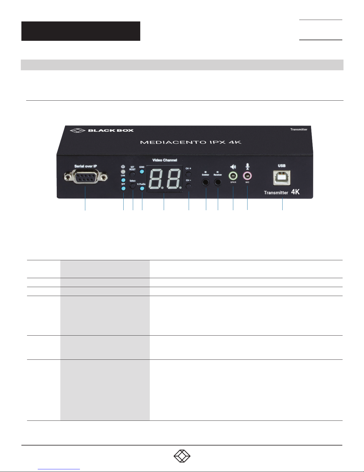
2.4.1 TRANSMITTER
Figure 2-1 shows the front panel of the transmitter. Table 2-1 describes its components.
NEED HELP?
LEAV E TH E TEC H TO US
LIVE 24/7
TECHNICAL
SUPPORT
1. 8 7 7. 8 7 7. 2 2 69
1 2 3 4 5 6 7 8 9 10 11
FIGURE 2-1. TRANSMITTER FRONT PANEL
TABLE 2-1. TRANSMITTER FRONT PANEL COMPONENTS
NUMBER IN
FIGURE 2-1
1 Serial over IP: RS-232 extension port Connects to source device’s RS-232 port
2a Power On status LED Lights steady when power on sequence is completed
2b Link LED for L AN link status
2c SFP LED for fiber link status
3a Set/Reset button
COMPONENT DESCRIPTION
• Goes out when LAN link between Transmitter and Receiver/Gigabit Ethernet Switch is off
• Blinks when LAN link between Transmitter and Receiver/Gigabit Ethernet Switch is on
and there is no image data stream on the LAN link
• Lights steady ON when LAN link between Transmitter and Receiver/Gigabit Ethernet
Switch is on and there is an image data stream on the LAN link
• Lights steady ON when Transmitter is powered on
• Blinks when there is an image data stream on the fiber link between Transmitter and
Receiver
Press to set a function, reset system, or reset to default
• Short press for setting the following functions
- EDID: Update EDID stored in Transmitter with EDID of display connecting to Transmitter
- Video Profile: Configure video profile with video or graphic mode
- Video Channel: Select video channel
• Long press (3 sec) for System Reset when no above functions selected to be set
• Longer press (6 sec) for Reset to Default when no above functions selected to be set
8
1. 87 7.8 7 7. 2 26 9 BLACKBOX.COM
Page 9

CHAPTER 2: OVERVIEW
TABLE 2-1 (CONTINUED). TRANSMITTER FRONT PANEL COMPONENTS
NEED HELP?
LEAV E TH E TEC H TO US
LIVE 24/7
TECHNICAL
SUPPORT
1. 8 7 7. 8 7 7. 2 2 69
NUMBER IN
FIGURE 2-1
3b Select button
4a EDID LED
4b V. Profile LED
5 Video Channel LED
6 CH+/CH- pushbuttons Press to change video channel
7
8
9
10
11
COMPONENT DESCRIPTION
Select EDID, video profile, or video channel
• Press to cycle through setting EDID / Video Profile / Video Channel / Quit “Select” in sequence
• Slow blink in the related LEDs when selecting EDID or Video Profile
• Slow blink in 7-segment LED display when selecting Video Channel
• Lights steady ON EDID LED indicator, Video Profile LED indicator and 7-segment LED display when quitting
“Select”
Indicates EDID update status
• Blinks when EDID update is ready to be set
• Press SET/RESET button to set/clear EDID update
• Lights steady ON when EDID stored in Transmitter is updated with EDID of displayconnected to Transmitter
• Not lit when EDID is not being updated
Indicates video/graphic mode
• Blinks when Video Profile is ready to be set
• Press SET/RESET button to set Video Profile to video/graphic mode
• The short OSD pops up on Receiver’s display to show the setting result of video/graphic mode
• Lights steady ON when Video Profile is set to video mode
• Not lit when Video Profile is set to graphic mode
7-segment LED display for Video Channel indication
• Blinks when Video Channel is ready to be set
• Press CH+ or CH- button to change video channel
• Press SET/RESET button to set the video channel change
IR Emitter
IR Receiver
Audio connector
Audio connector
USB Type B connector
Connector used for emitting signal of IR extension over IP
Connector used for receiving signal of IR extension over IP
Connector for analog audio output of audio extension over IP (speaker)
Connector for analog audio input of audio extension over IP (microphone)
Links to host source device for USB extension over IP
1. 87 7.8 7 7. 2 26 9 BLACKBOX.COM
9
Page 10
CHAPTER 2: OVERVIEW
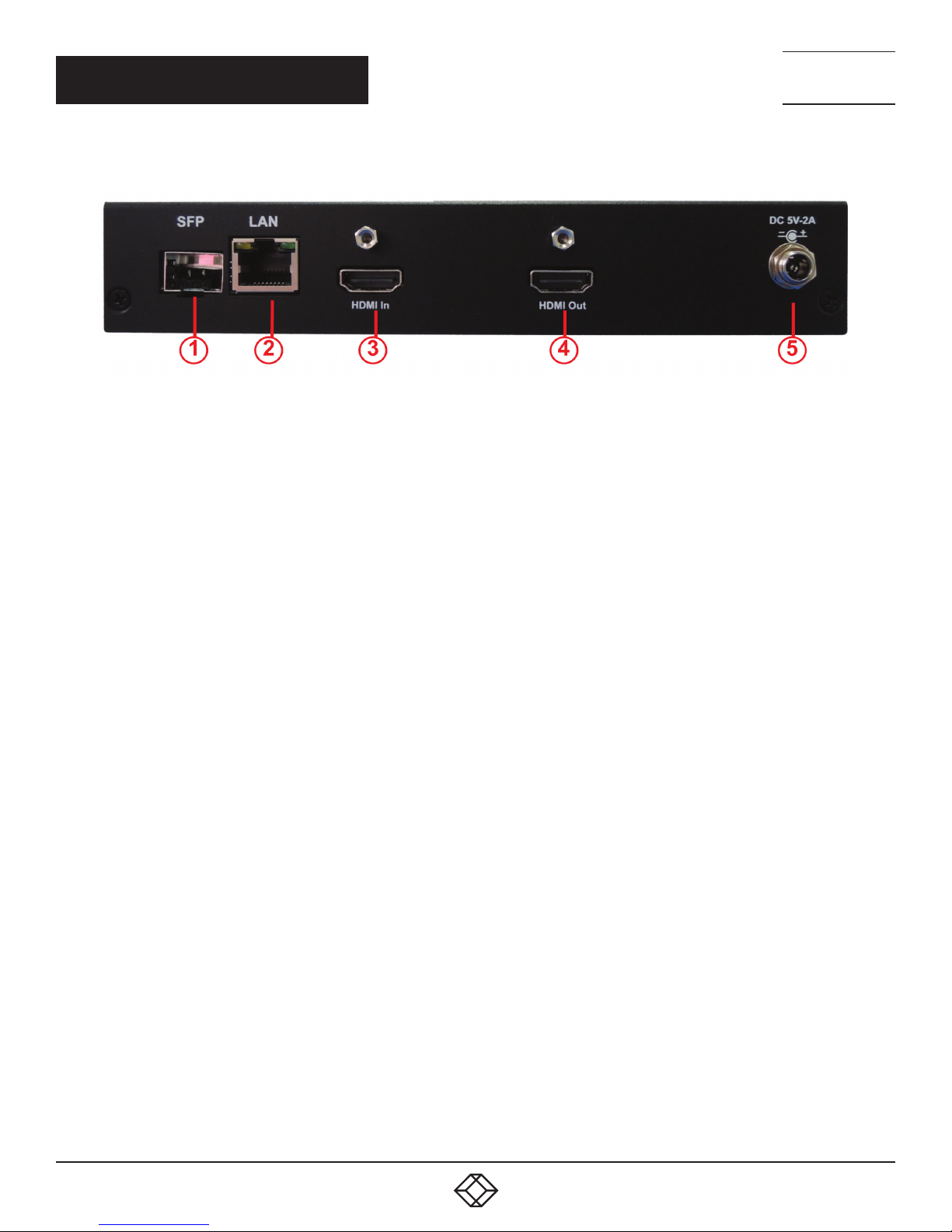
Figure 2-2 shows the back panel of the transmitter. Table 2-2 describes its components.
FIGURE 2-2. TRANSMITTER BACK PANEL
NEED HELP?
LEAV E TH E TEC H TO US
LIVE 24/7
TECHNICAL
SUPPORT
1. 8 7 7. 8 7 7. 2 2 69
10
1. 87 7.8 7 7. 2 26 9 BLACKBOX.COM
Page 11

CHAPTER 2: OVERVIEW
TABLE 2-2. TRANSMITTER BACK PANEL COMPONENTS
NEED HELP?
LEAV E TH E TEC H TO US
LIVE 24/7
TECHNICAL
SUPPORT
1. 8 7 7. 8 7 7. 2 2 69
NUMBER IN
FIGURE 2-2
1 SFP cage Fiberoptic SFP module for link between transmitter and receiver installs here
2 RJ-45 connector Used for LAN Link between transmitter and receiver/Gigabit Ethernet switch
3 HDMI In connector Connects to HDMI source for the source signal of HDMI extension over IP
4 HDMI Out connector Loops back the source signal to Transmitter’s connected display
5 5-VDC jack Links to 5-VDC power supply
COMPONENT DESCRIPTION
1. 87 7.8 7 7. 2 26 9 BLACKBOX.COM
11
Page 12

CHAPTER 2: OVERVIEW
2.4.2 RECEIVER
Figure 2-3 shows the front panel of the receiver. Table 2-3 describes its components.
NEED HELP?
LEAV E TH E TEC H TO US
LIVE 24/7
TECHNICAL
SUPPORT
1. 8 7 7. 8 7 7. 2 2 69
1 2 3 4 5 6 7 8 9 10 11 12
FIGURE 2-3. RECEIVER FRONT PANEL
TABLE 2-3. RECEIVER FRONT PANEL COMPONENTS
NUMBER IN
FIGURE 2-3
1 Serial over IP: RS-232 extension port Connects to sink device’s RS-232 por t
2a Power On status LED Lights steady when power on sequence is completed
2b Link LED for L AN link status
2c SFP LED for fiber link status
3a Set/Reset button
COMPONENT DESCRIPTION
• Goes out when LAN link between Transmitter and Receiver/Gigabit Ethernet Switch is off
• Blinks when LAN link between Transmitter and Receiver/Gigabit Ethernet Switch is on
and there is no image data stream on the LAN link
• Lights steady ON when LAN link between Transmitter and Receiver/Gigabit Ethernet
Switch is on and there is an image data stream on the LAN link
• Lights steady ON when Transmitter is powered on
• Blinks when there is an image data stream on the fiber link between Transmitter and
Receiver
Press to set a function, reset system, or reset to default
• Short press for setting the following functions
- EDID: Update EDID stored in Transmitter with EDID of display connecting to Receiver
- USB: Link or unlink USB extension
- Video Profile: Configure video profile with video or graphic mode
- Video Channel: Select video channel
• Long press (3 sec) for System Reset when no above functions selected to be set
• Longer press (6 sec) for Reset to Default when no above functions selected to be set
12
1. 87 7.8 7 7. 2 26 9 BLACKBOX.COM
Page 13

CHAPTER 2: OVERVIEW
TABLE 2-3 (CONTINUED). RECEIVER FRONT PANEL COMPONENTS
NEED HELP?
LEAV E TH E TEC H TO US
LIVE 24/7
TECHNICAL
SUPPORT
1. 8 7 7. 8 7 7. 2 2 69
NUMBER IN
FIGURE 2-3
3b Select button
4a EDID LED
4b USB Link Status :LED
4c V. Profile LED
5 Video Channel LED
6 CH+/CH- pushbuttons Press to change video channel
7
8
9
10
11
12
COMPONENT DESCRIPTION
Select EDID, video profile, or video channel
• Press to cycle through setting EDID / Video Profile / Video Channel / Quit “Select” in sequence
• Slow blink in the related LEDs when selecting EDID or Video Profile
• Slow blink in 7-segment LED display when selecting Video Channel
• Lights steady ON EDID LED indicator, Video Profile LED indicator and 7-segment LED display when quitting
“Select”
Indicates EDID update status
• Blinks when EDID update is ready to be set
• Press SET/RESET button to set/clear EDID update
• Lights steady ON when EDID stored in Transmitter is updated with EDID of displayconnected to Transmitter
• Not lit when EDID is not being updated
Indicates USB link status
• Blinks when USB link is ready to be set
• Press SET/RESET button to set USB link/unlink
• The short OSD pops up on Receiver’s display to show the setting result of USB link/unlink
• Lights steady ON when USB link is set
• Not lit when USB unlink is set
Indicates video/graphic mode
• Blinks when Video Profile is ready to be set
• Press SET/RESET button to set Video Profile to video/graphic mode
• The short OSD pops up on Receiver’s display to show the setting result of video/graphic mode
• Lights steady ON when Video Profile is set to video mode
• Not lit when Video Profile is set to graphic mode
7-segment LED display for Video Channel indication
• Blinks when Video Channel is ready to be set
• Press CH+ or CH- button to change video channel
• Press SET/RESET button to set the video channel change
IR Emitter
IR Receiver
Audio connector
Audio connector
(2) USB Type A
connectors
(2) USB Type A
connectors
Connector used for emitting signal of IR extension over IP
Connector used for receiving signal of IR extension over IP
Connector for analog audio input of audio extension over IP (microphone)
Connector for analog audio output of audio extension over IP (speaker)
Links to USB devices for USB extension over IP (USB 2.0)
Links to USB keyboard/mouse for USB extension over IP (USB HID)
1. 87 7.8 7 7. 2 26 9 BLACKBOX.COM
13
Page 14

CHAPTER 2: OVERVIEW
Figure 2-4 shows the back panel of the receiver. Table 2-4 describes its components.
FIGURE 2-4. RECEIVER BACK PANEL
NEED HELP?
LEAV E TH E TEC H TO US
LIVE 24/7
TECHNICAL
SUPPORT
1. 8 7 7. 8 7 7. 2 2 69
TABLE 2-4. RECEIVER BACK PANEL COMPONENTS
NUMBER IN
FIGURE 2-4
1 SFP cage Fiberoptic SFP module for link between transmitter and receiver installs here
2 RJ-45 connector Used for LAN Link between transmitter and receiver/Gigabit Ethernet switch
3 HDMI Out connector Connects to HDMI source for the sink signal of HDMI extension over IP
4 5-VDC jack Links to 5-VDC power supply
COMPONENT DESCRIPTION
14
1. 87 7.8 7 7. 2 26 9 BLACKBOX.COM
Page 15

NEED HELP?
LEAV E TH E TEC H TO US
LIVE 24/7
CHAPTER 3: CONNECTIONS
TECHNICAL
SUPPORT
1. 8 7 7. 8 7 7. 2 2 69
3.1 ONE-TO-ONE MAPPING EXTENSION
FIGURE 3-1. ONE-TO-ONE MAPPING EXTENSION
Use this to pair a single set of TX and RX. The default video channel on each unit is 1. This can also be adjusted on multiple RXs to
match a single TX, then press the “SET/RESET” button on the RX unit(s).
Fiber
OR
Copper
NOTE: The TX-RX link can use fiber
OR copper cable, but not both at
the same time.
FIGURE 3-2. ONE-TO-ONE CONNECTION
3.2 MULTICASTING
Multicasting enables you to install a matrix of TX and RX units for use as an extender matrix system over an IP network. A multicasting
application requires a Gigabit/1000-Mbps network switch.
For multicast-matrix installation, the Gigabit Managed Switch or Gigabit Smart Switch must support the IGMP V2 querier function and
Jumbo Frame (at least 8K) is required.
For each Transmitter (TX), set a unique video channel number ranging from 01–99 to avoid channel conflict. Each Receiver’s (RX) video
channel must correspond to the Transmitter’s (TX) video channel whose video content will be displayed on RX’s display. Press the “ SET/
RESET ” button of the RX unit to implement extension linking.
A multicasting application diagram is shown on the next page.
1. 87 7.8 7 7. 2 26 9 BLACKBOX.COM
15
Page 16

CHAPTER 3: CONNECTIONS
NEED HELP?
LEAV E TH E TEC H TO US
LIVE 24/7
TECHNICAL
SUPPORT
1. 8 7 7. 8 7 7. 2 2 69
FIGURE 3-3. TYPICAL MULTICASTING APPLICATION
16
1. 87 7.8 7 7. 2 26 9 BLACKBOX.COM
Page 17

NEED HELP?
LEAV E TH E TEC H TO US
LIVE 24/7
CHAPTER 4: NETWORK SETUP AND HARDWARE SWITCHING
1. Power on the Gigabit Switch and enable Jumbo Frame (8k) and IGMP v2.
2. Connect all transmitters and receivers to the Gigabit Switch using CATx cables.
3. Connect all transmitters with video sources, and all receivers with Display/TV using HDMI cables.
4. Connect an IR emitter cable to the transmitter’s or receiver’s IR Emitter Jack, and point the IR emitter to transmitter’s or receiver’s
connected device’s IR receiver window that you want to control.
5. Connect an IR Receiver cable to the transmitter’s or receiver’s IR Receiver Jack, and point the IR receiver to the transmitter’s or
receiver’s connected device’s IR remote.
6. Connect an RS-232 cable to the transmitter and receiver where a RS-232 controller or Display/TV/device can take RS-232
command.
NOTE: If the transmitter’s or receiver’s RS-232 port and the device’s RS-232 port are different genders, use a gender changer.
7. Plug-in a DC power adapter to all transmitters and receivers. The units power on.
8. Power on all Video Sources and start playing video.
9. Power on all Displays/TVs and select HDMI input. All displays/TVs show video depending on the video channel selected.
10. To assign different video channels (sources), use an IR Receiver cable or the 99-channel IR remote controller on the receiver side
to switch the source channel, or change the receiver’s video channel by using pushbuttons on the receiver.
11. Select the video channel by using pushbuttons (CH+/CH-) on every transmitter/receiver based on the link mapping, and set it up
by pressing the “Set/Reset” button. The 7-segment LED display (Video Channel) will stop blinking when the setting is completed.
12. To use the 99-channel IR remote controller, follow steps A through C below.
A. Press “CH+” or “CH-“ to scroll to the next or previous available video channel.
B. Press the number key “1” – “0” and “ENTER” to directly change to the specific video channel.
C. Press “OSD” to show the status information of the transmitter and receiver in the same link on the top left corner of the display
connected to the receiver. The status information includes:
Transmitter’s IP
Receiver’s IP and MAC address
Firmware version of this receiver
Device mode setting of this receiver (Extender or Matrix)
Current receiving video channel
Current video resolution
TECHNICAL
SUPPORT
1. 8 7 7. 8 7 7. 2 2 69
FIGURE 4-1. REMOTE CONTROL
1. 87 7.8 7 7. 2 26 9 BLACKBOX.COM
17
Page 18

NEED HELP?
LEAV E TH E TEC H TO US
LIVE 24/7
CHAPTER 5: HARDWARE OPERATION
TECHNICAL
SUPPORT
1. 8 7 7. 8 7 7. 2 2 69
5.1 EDID UPDATE BY BUTTONS
The MediaCento IPX 4K features EDID Management. In each video link of a transmitter unit (TX) and a receiver unit (RX), before
outputting the video (and/or audio) data, the source device connecting to the TX reads the EDID first to define the specification of
the video data it should support to output. The EDID can be the factory default, the display connecting to the TX or the sink device
(e.g. display, amplifier,….etc) connecting to RX, and be set up to one of these three types by pressing the “EDID Update” button
based on the application.
By default, the internal HDMI EDID (stored in the transmitter unit) is used. However, the EDID of the receiver’s HDMI output
connected device such as the display, amplifier,…etc, can be obtained and stored in the transmitter. It can support multi-channel
audio and 3D function from the device connecting to the receiver.
5.1.1 “EDID UPDATE” FOR HDMI SINK DEVICE ON TX OR RX SIDE
1. Press the “Select” button to make “EDID” LED blink in order to select the EDID Update function.
2. Press the “SET/RESET” button to set up the EDID Update function.
3. The “EDID” LED lights steady on when the EDID Update is completed.
4. In Extender device mode for TX/RX link, EDID Update will automatically perform when the video connection is established every
time or when the display connecting to Receiver unit is changed.
5.1.2 “EDID UPDATE” TO BE FACTORY DEFAULT
1. Make sure there is no function setting for “EDID”, “USB”, “V. profile” or “Video Channel” to be selected.
2. Press the button for 6 seconds to Reset to Default.
3. Do the above two steps for the transmitter and receiver of the same link.
5.2 AUDIO OVER IP EXTENSION
1. A computer has a Mic-In jack, as part of the sound card. To access this jack from the Receiver/RX unit, connect the microphone
to the Mic-in jack on the Receiver/RX unit.
2. To get the audio from the microphone into the computer, connect a 3.5-mm-to-3.5-mm stereo cable from the Line out jack on the
Transmitter unit to the Line in jack on the computer.
WARNING: DO NOT connect the cable from the Line out jack on the TX unit to the Mic In jack on the computer. Doing it will result in
audio “clipping” and may cause damage to the sound card.
NOTE: HDMI audio will always be passed through to the HDMI out connector on the Receiver unit. However, if a 3.5mm stereo cable
is connected to the Line in jack on the TX unit, the embedded HDMI audio is switched off. This allows the audio signal from Line in
jack (TX unit) to be received on the Line out jack (Receiver/RX unit).
18
1. 87 7.8 7 7. 2 26 9 BLACKBOX.COM
Page 19

NEED HELP?
LEAV E TH E TEC H TO US
LIVE 24/7
CHAPTER 5: HARDWARE OPERATION
TECHNICAL
SUPPORT
1. 8 7 7. 8 7 7. 2 2 69
When using a microphone, the audio behavior will differ between the device modes of Extender and Matrix,
Matrix Mode: The Mic- in jack is disabled in matrix mode. However, if an audio source is connected to the Line in jack on a
Transmitter/TX unit, the audio signal will be distributed to all Receiver/RX units that are set to the same video channel. Each
Receiver/RX unit will have a separate pair of power speakers connected to the Line out jack.
Extender Mode: In extender mode, separate microphones can be connected to each Receiver (RX) unit. The audio signal coming
from the microphone will be sent to the Transmitter (TX) unit on the same channel as the Receiver (RX) unit.
5.3 VIDEO PROFILE
The MediaCento IPX 4K provides two video profiles: Video mode and Graphic mode.
1. On the transmitter or receiver unit, press the “Select” button to make the “V. Profile” LED blink in order to select the Video Profile
function.
2. Press the “SET/RESET” button to set the Video Profile to Video/Graphic mode.
3. “V. Profile” LED lights steady ON when the Video Profile is set to Video mode.
4. “V. Profile” LED is not lit when the Video Profile is set to Graphic mode.
By default, the units are set in “Video Mode.” If the High-Definition signal is a video source, it will be displayed in optimal quality.
FIGURE 5-1. VIDEO MODE
1. 87 7.8 7 7. 2 26 9 BLACKBOX.COM
19
Page 20

NEED HELP?
LEAV E TH E TEC H TO US
LIVE 24/7
CHAPTER 5: HARDWARE OPERATION
If the High-Definition signal is a Graphic Source (e.g. images, pattern generator, etc.), press the Video Mode button on the rear
panel of Receiver (RX) until “Graphic Mode” is displayed in the foreground on the graphic image. Set the MediaCento IPX 4K to
Graphic Mode to maintain the sharpest possible image.
TECHNICAL
SUPPORT
1. 8 7 7. 8 7 7. 2 2 69
FIGURE 5-2. GRAPHIC MODE
5.4 HOTKEY VIDEO CHANNEL SWITCH ON RX SIDE
In addition to pushbutton, IR remote and Web UI, you can also use a keyboard connected to the receiver unit to switch the video
channel in matrix mode.
Press “Scroll Lock” twice within 1 sec, and then type in the channel number to which you would like to switch the channel. The
channel of RX is switched accordingly. For instance, press “Scroll Lock” twice within 1 sec, and then type in “99”. The channel of RX
is switched to channel 99.
NOTE: The keyboard MUST be connected to RX’s USB port with keyboard/mouse symbol only.
NOTE: K/M over IP function of RX must be enabled.
20
1. 87 7.8 7 7. 2 26 9 BLACKBOX.COM
Page 21

NEED HELP?
LEAV E TH E TEC H TO US
LIVE 24/7
CHAPTER 6: ACCESS TO WEB UI
1. Power on the Gigabit Switch and enable Jumbo Frame and IGMP.
2. Connect all Transmitter (TX) and Receiver (RX) units to the Gigabit Switch using CATx or fiberoptic cable to set up the matrix
extension network.
3. Connect all Transmitters (TXs) with video sources, and all Receivers (RXs) with Display/TV/Monitor using HDMI cables.
4. Get a PC for executing the Web browser, and connect this control PC to the Gigabit Switch via CATx cable.
5. Connect an IR emitter cable to the transmitter’s or receiver’s IR Emitter Jack, and point the IR emitter to transmitter’s or receiver’s
connected device’s IR receiver window that you want to control.
6. Connect an IR Receiver cable to transmitter’s or receiver’s IR Receiver Jack, and point the IR receiver to transmitter’s or receiver’s
connected device’s IR remote.
7. Connect an RS-232 straight cable to the transmitter or receiver where an RS=232 controller or Display/TV/device can take RS-232
commands.
NOTE: If the transmitter’s or receiver’s RS-232 port and the device’s RS-232 port are different gender, use a gender changer.
8. Plug-in a DC power adapter to all Transmitter (TX) and Receiver (RX). units, and power on the units.
9. Power on all Video Sources and start playing video.
10. Set the control PC’s IP setting:
Select Internet Protocol Version 4 (TCP/IPv4)
IP address: 169.254.2.1 or the other IP address within 169.254.XXX.XXX
Netmask: 255.255.0.0
TECHNICAL
SUPPORT
1. 8 7 7. 8 7 7. 2 2 69
FIGURE 6-1. PROPERTIES SCREEN
1. 87 7.8 7 7. 2 26 9 BLACKBOX.COM
21
Page 22

NEED HELP?
LEAV E TH E TEC H TO US
LIVE 24/7
CHAPTER 6: ACCESS TO WEB UI
11. Access the Web Interface Control Software.
A. Randomly select a receiver in the matrix extension network and unlink it
B. The OSD will immediately appear on the display connected to the selected receiver. The selected receiver’s IP and MAC address
are shown in the OSD.
Selected RX’s IP address
TECHNICAL
SUPPORT
1. 8 7 7. 8 7 7. 2 2 69
FIGURE 6-2. SELECTED RX’S IP ADDRESS
C. Re-link the selected receiver to matrix extension network by re-connecting the CATx or fiberoptic cable.
D. Access the Web browser via the control PC by using the selected RX’s IP address shown in the OSD ( http://169.254.XXX.XXX/ ).
E. When the access is done, the home page of Web Interface Control Software will appear.
VX-HDMI-4KIP-TX Transm itter V.6.4.12 Build 2204
22
FIGURE 6-3. HOME PAGE
1. 87 7.8 7 7. 2 26 9 BLACKBOX.COM
Page 23

NEED HELP?
LEAV E TH E TEC H TO US
LIVE 24/7
CHAPTER 7: OPERATION FOR WEB UI
TECHNICAL
SUPPORT
1. 8 7 7. 8 7 7. 2 2 69
7.1 CONFIGURING IP MODE
By default, the transmitter unit (TX) and the receiver unit (RX) are set to be in DHCP Mode, automatically showing the default IP and
subnet mask. If a DHCP server is not available, the device will automatically use IP addresses at 169.254.xxx.xxx range with subnet
mask 255.255.0.0.
You do not need to change it unless you know what IP address you can assign to this device.
To assign the static IP, all transmitters and receivers need to be at same IP domain and corresponding subnet mask.
FIGURE 7-1. IP MODE SCREEN
When you apply new settings, reboot the unit to take effect. To reboot the TX unit or RX unit:
1. Press the “SET/RESET” button on the unit for 3 seconds.
OR
2. Click the Reboot button on the Web interface.
1. 87 7.8 7 7. 2 26 9 BLACKBOX.COM
23
Page 24

CHAPTER 7: OPERATION FOR WEB UI
Reboot button
NEED HELP?
LEAV E TH E TEC H TO US
LIVE 24/7
TECHNICAL
SUPPORT
1. 8 7 7. 8 7 7. 2 2 69
FIGURE 7-2. REBOOT BUTTON ON WEB UI
7.2 DEVICE MODE OF EXTENSION APPLICATION
The Extension application has two device modes: Matrix and Extender. In Matrix mode, multiple Receiver (RX) units can receive
signals from multiple (or a single) Transmitter (TX) units in the same network. In Extender mode, only a single Receiver (RX) unit
can receive signals from Transmitter (TX) unit with the same channel. By default, the Extension Application is configured to Matrix
Mode.
7.2.1 HOW TO CHANGE TO EXTENDER MODE
1. By default, the Device Mode of TX and RX unit is Matrix Mode.
2. Click the Network tab and click Extender button. When selected, the Extender button will be highlighted in blue, and then click
the Apply button.
24
1. 87 7.8 7 7. 2 26 9 BLACKBOX.COM
Page 25

CHAPTER 7: OPERATION FOR WEB UI
NEED HELP?
LEAV E TH E TEC H TO US
LIVE 24/7
TECHNICAL
SUPPORT
1. 8 7 7. 8 7 7. 2 2 69
FIGURE 7-3. DEVICE MODE SCREEN
3. A message will be displayed, indicating that the casting mode has been applied to the TX unit.
FIGURE 7-4. CASTING MODE MESSAGE
4. After a few seconds, another message will be displayed stating that the TX unit must be rebooted. Reboot the transmitter and the
new setting will take effect.
FIGURE 7-5. REBOOT MESSAGE
1. 87 7.8 7 7. 2 26 9 BLACKBOX.COM
25
Page 26

CHAPTER 7: OPERATION FOR WEB UI
5. Reboot the TX unit by one of these methods:
Press the “Set/Reset” on the TX unit for 3 seconds.
OR
Click the Reboot button on the Web interface.
NEED HELP?
LEAV E TH E TEC H TO US
LIVE 24/7
TECHNICAL
SUPPORT
1. 8 7 7. 8 7 7. 2 2 69
FIGURE 7-6. SET/RESET AND REBOOT BUTTON ON THE WEB UI
6. Repeat steps 1 through 5 in sequence for each TX and RX on the network.
26
1. 87 7.8 7 7. 2 26 9 BLACKBOX.COM
Page 27

NEED HELP?
LEAV E TH E TEC H TO US
LIVE 24/7
CHAPTER 7: OPERATION FOR WEB UI
TECHNICAL
SUPPORT
1. 8 7 7. 8 7 7. 2 2 69
7.2.2 HOW TO CHANGE TO MATRIX MODE
1. Click the Network tab and click Matrix button. When selected, the Matrix button will be highlighted in blue, and then click the Apply
button.
FIGURE 7-7. DEVICE MODE SCREEN, MATRIX MODE
2. The IP Mode has to be assigned to either DHCP or Static mode.
CAUTION: With any changes in device modes or channel setting changes, you MUST REBOOT each Transmitter (TX) and Receiver
(RX) unit for the new settings to take effect.
1. 87 7.8 7 7. 2 26 9 BLACKBOX.COM
27
Page 28

CHAPTER 7: OPERATION FOR WEB UI
7.3 JUMBO FRAME REQUIREMENT FOR THE LINK BETWEEN TX AND RX
Check “Enable Jumbo Frame (recommended)” and click “Apply” to add this requirement.
Uncheck “Enable Jumbo Frame (recommended)” and click “Apply” to remove this requirement.
Make all TXs and RXs in the network on the same status for this requirement.
NEED HELP?
LEAV E TH E TEC H TO US
LIVE 24/7
TECHNICAL
SUPPORT
1. 8 7 7. 8 7 7. 2 2 69
28
FIGURE 7-8. ENABLE JUMBO FRAMES
1. 87 7.8 7 7. 2 26 9 BLACKBOX.COM
Page 29

NEED HELP?
LEAV E TH E TEC H TO US
LIVE 24/7
CHAPTER 7: OPERATION FOR WEB UI
TECHNICAL
SUPPORT
1. 8 7 7. 8 7 7. 2 2 69
7.4 AUTOMATICALLY COPY EDID OF RX’S DISPLAY
1. By default, in Matrix device mode for a TX/RX link, EDID copy doesn’t automatically perform when an TX/RX link is established
every time or the display connecting to RX is changed. This function allows EDID copy to automatically perform based on the
specified RX’s display in Matrix device mode.
2. Log in to the Web UI of the specified RX for which this function is to be enabled.
3. Check “Automatically Copy EDID from this Receiver Video Output” and click “Apply” to enable this function.
FIGURE 7-9. COPY EDID
1. 87 7.8 7 7. 2 26 9 BLACKBOX.COM
29
Page 30

NEED HELP?
LEAV E TH E TEC H TO US
LIVE 24/7
CHAPTER 7: OPERATION FOR WEB UI
TECHNICAL
SUPPORT
1. 8 7 7. 8 7 7. 2 2 69
7.5 OUTPUT VIDEO SCALING IN RX
This function allows the specified RX scaling its output video based on the resolution settings. The default setting is “Auto Detect
(Per EDID)” which means the RX’s output video is automatically scaled up/down based on the EDID of the display connecting to RX.
“Pass-Through” mode means RX directly outputs the video without any scaling.
Select the needed setting and click “Apply” to activate it.
30
FIGURE 7-10. OUTPUT VIDEO SCALING IN RX
1. 87 7.8 7 7. 2 26 9 BLACKBOX.COM
Page 31

NEED HELP?
LEAV E TH E TEC H TO US
LIVE 24/7
CHAPTER 7: OPERATION FOR WEB UI
TECHNICAL
SUPPORT
1. 8 7 7. 8 7 7. 2 2 69
7.6 LAST IMAGE OUTPUT TIME FOR SOURCE CONTENT LOST
When the TX’s source content is lost, the RX’s video output will be frozen in the last image for a time period from 3 sec to 60 sec.
Select the needed time and click “Apply” to activate it.
FIGURE 7-11 TIMEOUT FOR LOST CONTENT
1. 87 7.8 7 7. 2 26 9 BLACKBOX.COM
31
Page 32

CHAPTER 7: OPERATION FOR WEB UI
7.7 OUTPUT VIDEO ROTATION IN RX
The output video of the individual RX can rotate by 90°, 180° and 270°.
NEED HELP?
LEAV E TH E TEC H TO US
LIVE 24/7
TECHNICAL
SUPPORT
1. 8 7 7. 8 7 7. 2 2 69
32
FI GURE 7-12. VID EO O R IENTATION
1. 87 7.8 7 7. 2 26 9 BLACKBOX.COM
Page 33

NEED HELP?
LEAV E TH E TEC H TO US
LIVE 24/7
CHAPTER 7: OPERATION FOR WEB UI
TECHNICAL
SUPPORT
1. 8 7 7. 8 7 7. 2 2 69
7.8 SERIAL (RS-232) OVER IP EXTENSION
The MediaCento IPX 4K supports RS-232 passthrough, allowing the control of remote RS-232 devices (near the Receiver/RX unit)
from the source (Transmitter/TX unit) location. The RS-232 host (controller) and the device (client) must be set to the same baud
rate. In addition, the correct baud rate must be set on the Transmitter/TX and Receiver/RX units that are being used to control the
RS-232 client.
1. Access the Web Interface Control Software using the RX’s IP address http://169.254.XXX.XXX/.
2. Click the Functions tab and locate the Serial over IP section.
3. Make sure that the Enabled Serial over IP box is checked as shown in the screen.
FIGURE 7-13. ENABLE SERIAL OVER IP BOX CHECKED
1. 87 7.8 7 7. 2 26 9 BLACKBOX.COM
33
Page 34

CHAPTER 7: OPERATION FOR WEB UI
4. After selecting the needed value, click the Apply button.
5. Reboot to have the new setting take effect.
6. Repeat the above steps in the TX on the link.
NEED HELP?
LEAV E TH E TEC H TO US
LIVE 24/7
TECHNICAL
SUPPORT
1. 8 7 7. 8 7 7. 2 2 69
34
FIGURE 7-14. REPEAT STEPS
1. 87 7.8 7 7. 2 26 9 BLACKBOX.COM
Page 35

NEED HELP?
LEAV E TH E TEC H TO US
LIVE 24/7
CHAPTER 7: OPERATION FOR WEB UI
TECHNICAL
SUPPORT
1. 8 7 7. 8 7 7. 2 2 69
7.9 USB OVER IP EXTENSION
When connecting USB devices to the MediaCento IPX 4K, the functionality is similar to video and RS-232.
1. Extender Mode: In Extender mode, only a single Receiver (RX) will be able to communicate with a Transmitter (TX).
The USB control is communication directly between Transmitter (TX) and Receiver (RX).
2. Matrix Mode: In Matrix mode, the USB host device can be controlled from one of multiple Receiver (RX) units at a time.
The USB link controls each Receiver/RX in order to enable USB on each RX. In matrix mode, the MediaCento IPX 4K behaves like
a USB hub.
7.10 MATRIX CONNECTION MANAGEMENT W/ DISPLAYING TX’S SOURCE CONTENT
1. Set up a matrix extension network by connecting all TXs and RXs to a Gigabit Switch Hub (supporting IGMP, 8K jumbo frame)
with CATx cable.
2. Also connect a PC to the same Gigabit Switch Hub with CATx cable. Set this PC’s IP domain and subnet mask to be
169.254.XXX.XXX and 255.255.0.0 under Internet Protocol Version 4 (TCP/IPv4).
3. Unlink an RX from the network and get this RX’s IP and MAC address shown on the display connected to this RX as follows.
Use this RX’s IP address http://169.254.XXX.XXX/ to access the Web UI (Web Interface Control Software).
4. Re-link the RX to the network.
5. Make sure to set all TXs and RXs to be in Matrix mode (default setting is Matrix mode).
6. Click the “Matrix” Tab in Web UI, and then the matrix connection grid table appears.
7. In the grid table, click the blank space mapped to the coordinate of TX (horizontal row, named with Channel##) and RX (vertical
column, named with Receiver: #) to which you will connect.
8. The blank space clicked for a connection will turn to green.
9. Click the “Apply” button to set the connection.
10. Click the “Refresh” button to display the updated status of all TXs and RXs in the matrix extension network.
11. Check “Show OSD” function to show the index number of the display connected to RX.
12. Uncheck “Show OSD” function to remove the index number of display connected to RX.
FIGURE 7-15. SELECTED RX’S IP ADDRESS
1. 87 7.8 7 7. 2 26 9 BLACKBOX.COM
35
Page 36

NEED HELP?
LEAV E TH E TEC H TO US
LIVE 24/7
CHAPTER 7: OPERATION FOR WEB UI
13. In the grid table, there is a hyperlink to each TX’s or RX’s Web UI, which is embedded in “Channel##” (standing for TX in the matrix
extension network) or “Receiver: #” (standing for RX in the matrix extension network). Point the mouse cursor to any “Channel##”
or “Receiver: #” and click the right button of mouse to access the Web UI accordingly.
TECHNICAL
SUPPORT
1. 8 7 7. 8 7 7. 2 2 69
36
FIGURE 7-16. GRID TABLE
1. 87 7.8 7 7. 2 26 9 BLACKBOX.COM
Page 37

NEED HELP?
LEAV E TH E TEC H TO US
LIVE 24/7
CHAPTER 7: OPERATION FOR WEB UI
TECHNICAL
SUPPORT
1. 8 7 7. 8 7 7. 2 2 69
7.11 VIDEO WALL
1. Set up a matrix extension network by connecting all TXs and RXs to a Gigabit Switch Hub (supporting IGMP, 8K jumbo frame)
with CATx cable.
2. Connect a PC to the same Gigabit Switch Hub with CATx cable. Set this PC’s IP domain and subnet mask to be 169.254.XXX.
XXX and 255.255.0.0.
3. Make sure and set all TXs and RXs to be in Matrix mode (default setting is Matrix mode).
4. Click the “Video Wall” Tab in Web UI, and then the video wall control panel appears.
FIGURE 7-17. VIDEO WALL CONTROL PANEL
1. 87 7.8 7 7. 2 26 9 BLACKBOX.COM
37
Page 38

CHAPTER 7: OPERATION FOR WEB UI
5. The following is the setting procedure.
STEP 1: Set common values of all devices.
1A. Set Bezel and Gap Compensation
This step is used to configure the bezel and gap compensation. If you do not need this, just set all values to 0.
Follow the picture and input the size of the monitor used. Note that the unit is 0.1 mm and the value MUST be an integer.
NEED HELP?
LEAV E TH E TEC H TO US
LIVE 24/7
TECHNICAL
SUPPORT
1. 8 7 7. 8 7 7. 2 2 69
FIGURE 7-18. BEZEL AND GAP COMPENSATION SCREEN
38
1. 87 7.8 7 7. 2 26 9 BLACKBOX.COM
Page 39

CHAPTER 7: OPERATION FOR WEB UI
1B. Set Wall Size
Set “Vertical Monitor Count” from 1 to 8 based on the application
Set “Horizontal Monitor Count” from 1 to 8 based on the application
NEED HELP?
LEAV E TH E TEC H TO US
LIVE 24/7
TECHNICAL
SUPPORT
1. 8 7 7. 8 7 7. 2 2 69
FIGURE 7-19. SET VERTICAL MONITOR COUNT SCREEN
1. 87 7.8 7 7. 2 26 9 BLACKBOX.COM
39
Page 40

CHAPTER 7: OPERATION FOR WEB UI
NEED HELP?
LEAV E TH E TEC H TO US
LIVE 24/7
TECHNICAL
SUPPORT
1. 8 7 7. 8 7 7. 2 2 69
FIGURE 7-20. SET HORIZONTAL MONITOR COUNT SCREEN
40
1. 87 7.8 7 7. 2 26 9 BLACKBOX.COM
Page 41

NEED HELP?
LEAV E TH E TEC H TO US
LIVE 24/7
CHAPTER 7: OPERATION FOR WEB UI
STEP 2: Setup Row and Column Position for Each Display attached to RX
2A. Check “Show OSD” to show the index number on each RX’s display in order to identify each RX.
2B. After setting the video wall size, move the mouse cursor to each display diagram, and click the right button of the mouse to
assign the RX mapped to the display’s position in video wall.
TECHNICAL
SUPPORT
1. 8 7 7. 8 7 7. 2 2 69
2C. Go through all RXs one by one by following the above steps.
FIGURE 7-21. SET VIDEO WALL SIZE
1. 87 7.8 7 7. 2 26 9 BLACKBOX.COM
41
Page 42

APPENDIX A. FIBER MODULES AND CABLES
A 1000-Mbps SFP fiber transceiver is used for high-speed connection expansion.
1000-Mbps LC, multimode SFP fiber transceiver
1000-Mbps LC, single-mode 10 km SFP fiber transceiver
NEED HELP?
LEAV E TH E TEC H TO US
LIVE 24/7
TECHNICAL
SUPPORT
1. 8 7 7. 8 7 7. 2 2 69
42
1. 87 7.8 7 7. 2 26 9 BLACKBOX.COM
Page 43

APPENDIX B: REGULATORY INFORMATION
B.1 CE AND ROHS2
This product complies with CE and ROHS2 certifications.
NEED HELP?
LEAV E TH E TEC H TO US
LIVE 24/7
TECHNICAL
SUPPORT
1. 8 7 7. 8 7 7. 2 2 69
1. 87 7.8 7 7. 2 26 9 BLACKBOX.COM
43
Page 44

NEED HELP?
LEAV E TH E TEC H TO US
LIVE 24/7
APPENDIX B: REGULATORY INFORMATION
TECHNICAL
SUPPORT
1. 8 7 7. 8 7 7. 2 2 69
B.2 NOM STATEMENT
1. Todas las instrucciones de seguridad y operación deberán ser leídas antes de que el aparato eléctrico sea operado.
2. Las instrucciones de seguridad y operación deberán ser guardadas para referencia futura.
3. Todas las advertencias en el aparato eléctrico y en sus instrucciones de operación deben ser respetadas.
4. Todas las instrucciones de operación y uso deben ser seguidas.
5. El aparato eléctrico no deberá ser usado cerca del agua—por ejemplo, cerca de la tina de baño, lavabo, sótano mojado o cerca
de una alberca, etc.
6. El aparato eléctrico debe ser usado únicamente con carritos o pedestales que sean recomendados por el fabricante.
7. El aparato eléctrico debe ser montado a la pared o al techo sólo como sea recomendado por el fabricante.
8. Servicio—El usuario no debe intentar dar servicio al equipo eléctrico más allá a lo descrito en las instrucciones de operación.
Todo otro servicio deberá ser referido a personal de servicio calificado.
9. El aparato eléctrico debe ser situado de tal manera que su posición no interfiera su uso. La colocación del aparato eléctrico
sobre una cama, sofá, alfombra o superficie similar puede bloquea la ventilación, no se debe colocar en libreros o gabinetes que
impidan el flujo de aire por los orificios de ventilación.
10. El equipo eléctrico deber ser situado fuera del alcance de fuentes de calor como radiadores, registros de calor, estufas u otros
aparatos (incluyendo amplificadores) que producen calor.
11. El aparato eléctrico deberá ser connectado a una fuente de poder sólo del tipo descrito en el instructivo de operación, o como
se indique en el aparato.
12. Precaución debe ser tomada de tal manera que la tierra fisica y la polarización del equipo no sea eliminada.
13. Los cables de la fuente de poder deben ser guiados de tal manera que no sean pisados ni pellizcados por objetos colocados
sobre o contra ellos, poniendo particular atención a los contactos y receptáculos donde salen del aparato.
14. El equipo eléctrico debe ser limpiado únicamente de acuerdo a las recomendaciones del fabricante.
15. En caso de existir, una antena externa deberá ser localizada lejos de las lineas de energia.
16. El cable de corriente deberá ser desconectado del cuando el equipo no sea usado por un largo periodo de tiempo.
17. Cuidado debe ser tomado de tal manera que objectos liquidos no sean derramados sobre la cubierta u orificios de ventilación.
18. Servicio por personal calificado deberá ser provisto cuando:
A: El cable de poder o el contacto ha sido dañado; u
B: Objectos han caído o líquido ha sido derramado dentro del aparato;o
C: El aparato ha sido expuesto a la lluvia; o
D: El aparato parece no operar normalmente o muestra un cambio en su desempeño; o
E: El aparato ha sido tirado o su cubierta ha sido dañada.
44
1. 87 7.8 7 7. 2 26 9 BLACKBOX.COM
Page 45

NEED HELP?
LEAV E TH E TEC H TO US
LIVE 24/7
APPENDIX C: DISCLAIMER/TRADEMARKS
TECHNICAL
SUPPORT
1. 8 7 7. 8 7 7. 2 2 69
C.1 DISCLAIMER
Black Box Corporation shall not be liable for damages of any kind, including, but not limited to, punitive, consequential or cost of cover
damages, resulting from any errors in the product information or specifications set forth in this document and Black Box Corporation
may revise this document at any time without notice.
C.2 TRADEMARKS USED IN THIS MANUAL
Black Box and the Double Diamond logo are registered trademarks of Black Box Corporation.
Any other trademarks mentioned in this manual are acknowledged to be the property of the trademark owners.
1. 87 7.8 7 7. 2 26 9 BLACKBOX.COM
45
Page 46

NOTES
__________________________________________________________________________________________________
__________________________________________________________________________________________________
__________________________________________________________________________________________________
__________________________________________________________________________________________________
__________________________________________________________________________________________________
__________________________________________________________________________________________________
NEED HELP?
LEAV E TH E TEC H TO US
LIVE 24/7
TECHNICAL
SUPPORT
1. 8 7 7. 8 7 7. 2 2 69
__________________________________________________________________________________________________
_
_________________________________________________________________________________________________
__________________________________________________________________________________________________
__________________________________________________________________________________________________\
__________________________________________________________________________________________________
__________________________________________________________________________________________________
__________________________________________________________________________________________________
__________________________________________________________________________________________________
_________________________________________________________________________________________________
__________________________________________________________________________________________________
__________________________________________________________________________________________________
__________________________________________________________________________________________________
46
1. 87 7.8 7 7. 2 26 9 BLACKBOX.COM
Page 47

NOTES
__________________________________________________________________________________________________
__________________________________________________________________________________________________
__________________________________________________________________________________________________
__________________________________________________________________________________________________
__________________________________________________________________________________________________
__________________________________________________________________________________________________
NEED HELP?
LEAV E TH E TEC H TO US
LIVE 24/7
TECHNICAL
SUPPORT
1. 8 7 7. 8 7 7. 2 2 69
__________________________________________________________________________________________________
_
_________________________________________________________________________________________________
__________________________________________________________________________________________________
__________________________________________________________________________________________________\
__________________________________________________________________________________________________
__________________________________________________________________________________________________
__________________________________________________________________________________________________
__________________________________________________________________________________________________
_________________________________________________________________________________________________
__________________________________________________________________________________________________
__________________________________________________________________________________________________
1. 87 7.8 7 7. 2 26 9 BLACKBOX.COM
47
Page 48

NEED HELP?
LEAVE THE TECH TO US
LIVE 24/7
TECHNICAL
SUPPORT
1.877.877.2269
© COPYRIGHT 2017 BLACK BOX CORPORATION. ALL RIGHTS RESERVED.
 Loading...