

Page 1

STEP X - Name of Step
24/7 TECHNICAL SUPPORT AT 877.877.2269 OR VISIT BLACKBOX.COM
VX-HDMI-4KIP-TX, VX-HDMI-4KIP-RX
MEDIACENTO
IPX 4K
QUICK START GUIDE
Page 2
STEP 1 - Check the Package Contents
VX-HDMI-4KIP-TX PACKAGE CONTENTS
• (1) MEDIACENTO IPX 4K TRANSMITTER
• (1) 5-VDC, 3-A POWER SUPPLY
• (1) IR BLASTER CABLE
• (1) USB 2.0 CABLE
• (1) AUDIO/MIC CABLE
VX-HDMI-4KIP-RX PACKAGE CONTENTS
• (1) MEDIACENTO IPX 4K RECEIVER
• (1) 5-VDC, 3-A POWER SUPPLY
• (1) IR RECEIVER CABLE
• (1) IR REMOTE CONTROL
AD DITON AL ITEMS YO U MAY NE ED
• (1) FIBER OPTIC SFP MODULE PER TX
OR RX UNIT (SEE TABLE 1, BELOW)
TABLE 1. COMPATIBLE SFPS
PRODUCT CODE DESCRIPTION
LFP411 SFP, 1250-Mbps Fiber with Extended Diagnostics, 850 -nm Multimode, 550 m LC
LF P412 SFP, 1250-Mbps Fiber with Extended Diagnostics, 1310-nm Multimode, 2 km LC
LFP413 SFP, 1250-Mbps Fiber with Extended Diagnostics, 1310-nm Single-Mode, 10 km LC
LFP414 SFP, 1250-Mbps Fiber with Extended Diagnostics, 1310-nm Single-Mode, 30 km LC
LFP418 SFP, 1250-Mbps Fiber with Extended Diagnostics, 1550-nm Single-Mode, 80 km, LC
NOTE: Also should support most gigabit fiber
SFP modules.
Page 3
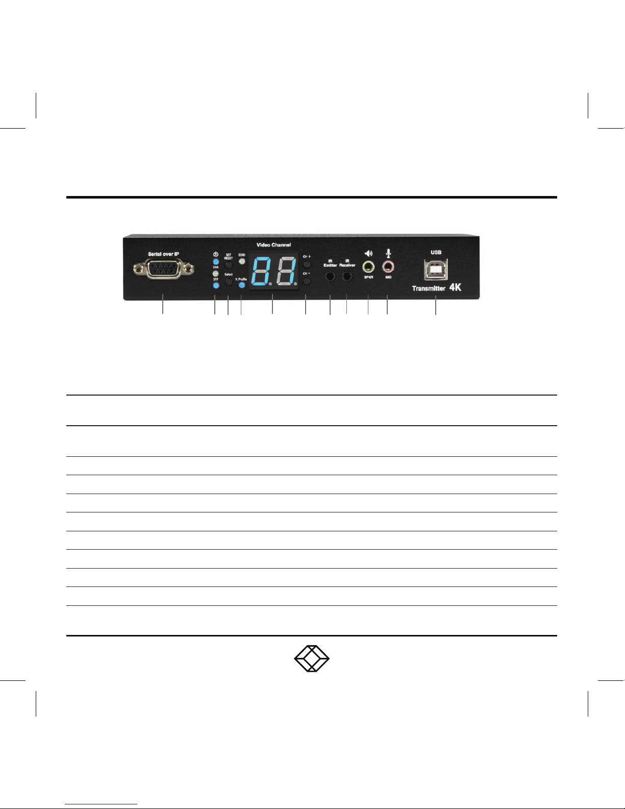
STEP 2A - Transmitter (TX) Front Panel
TABLE 2. TRANSMITTER FRONT PANEL COMPONENTS
NUMBER IN
DIAGRAM ABOVE
COMPONENT DESCRIPTION
1 DB9 connector
Serial over IP RS-232 extension port, connects to source
device
2a Power ON Status LED Lights steady when power on sequence is completed
2b Link LED Indicates LAN Link status
3a Set/Reset button Press to set a function, reset system or reset to default
3b Select button Select EDID, video profile or video channel
4a EDID LED Indicates EDID update status
4b V. Profile LED Indicates video/graphic mode
5 Video Channel LED 7-segment LED display indicates Video Channel
6 CH+/CH- pushbuttons Press to change video channel
1 2 3 4 5 6 7 8 9 10 11
Page 4
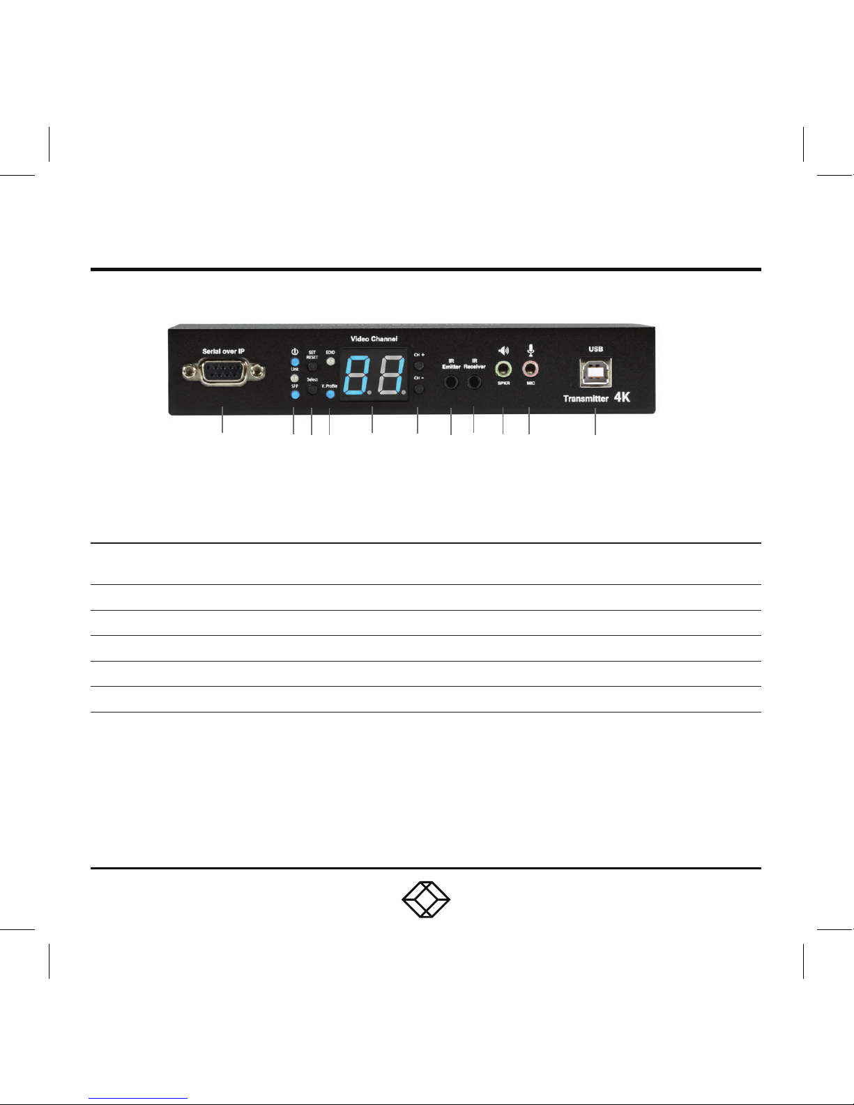
STEP 2A (CONTINUED) - Transmitter (TX) Front Panel
TABLE 2 (CONTINUED). TRANSMITTER FRONT PANEL COMPONENTS
NUMBER IN
DIAGRAM ABOVE
COMPONENT DESCRIPTION
7 IR Emitter connector Used for emitting signal of IR extension over IP
8 IR Receiver connector Used for receiving signal of IR extension over IP
9 Audio connector Connects to analog audio output (speaker)
10 Audio connector Connects to analog audio input (microphone)
11 USB Type B connector Links to host source device for USB extension over IP
1 2 3 4 5 6 7 8 9 10 11
Page 5

STEP 2B - Transmitter (TX) Back Panel
1 2 3 4 5
TABLE 3. TRANSMITTER BACK PANEL COMPONENTS
NUMBER IN
DIAGRAM ABOVE
COMPONENT DESCRIPTION
1 SFP cage Fiberoptic module for link between TX and RX installs here
2 RJ-45 connector Used for LAN Link between TX and RX/Gigabit Ethernet switch
3 HDMI IN connector Connects to HDMI source for HDMI extension over IP
4 HDMI OUT connector Loops back the source signal to TX unit's connected display
5 5-VDC jack Links to 5-VDC power supply
Page 6

STEP 3A - Receiver (RX) Front Panel
TABLE 4. RECEIVER FRONT PANEL COMPONENTS
NUMBER IN
DIAGRAM ABOVE
COMPONENT DESCRIPTION
1 DB9 connector Serial over IP RS-232 extension port, connects to sink device
2a Power ON Status LED Lights steady when power on sequence is completed
2b Link LED Indicates LAN Link status
2c SFP LED Indicates Fiber Link status
3a Set/Reset button Press to set a function, reset system or reset to default
3b Select button Select EDID, video profile or video channel
4a EDID LED Indicates EDID update status
4b USB Link LED Indicates USB link status
4c V. Profile LED Indicates video/graphic mode
5 Video Channel LED 7-segment LED display indicates Video Channel
1 2 3 4 5 6 7 8 9 10 11 12
Page 7

STEP 3A (CONTINUED) - Receiver (RX) Front Panel
TABLE 4 (CONTINUED). RECEIVER FRONT PANEL COMPONENTS
NUMBER IN
DIAGRAM AT LEFT
COMPONENT DESCRIPTION
6 CH+/CH- pushbuttons Press to change video channel
7 IR Emitter connector Used for emitting signal of IR extension over IP
8 IR Receiver connector Used for receiving signal of IR extension over IP
9 Audio connector Connects to analog audio input (microphone)
10 Audio connector Connects to analog audio output (speaker)
11 (2) USB Type A connectors Links to USB 2.0 devices for USB extension over IP
12 (2) USB Type A connectors
Links to USB HID keyboard/mouse for USB extension
over IP
Page 8

STEP 3B - Receiver (RX) Back Panel
TABLE 5. RECEIVER BACK PANEL COMPONENTS
NUMBER IN
DIAGRAM ABOVE
COMPONENT DESCRIPTION
1 SFP cage Fiberoptic module for link between TX and RX installs here
2 RJ-45 connector Used for LAN Link between TX and RX/Gigabit Ethernet switch
3 HDMI OUT connector Connects to HDMI sink for HDMI extension over IP
4 5-VDC jack Links to 5-VDC power supply
1 2 3 4
Page 9

STEP 4 - Network Setup and Hardware Switching
NE T WORK SET UP AND HW SW ITCHI NG
1. Power on the Gigabit Switch and enable
Jumbo Frame (8k) and IGMP v2.
2. Connect all transmitters and receivers
to the Gigabit Switch using CATx cables.
3. Connect all transmitters with video sources,
and all receivers with Display/TV using HDMI
cables.
4. Connect an IR emitter cable to the
transmitter’s or receiver’s IR Emitter Jack,
and point the IR emitter to transmitter’s
or receiver’s connected device’s IR receiver
window that you want to control.
5. Connect an IR Receiver cable to the
transmitter’s or receiver’s IR Receiver Jack,
and point the IR receiver to the transmitter’s
or receiver’s connected device’s IR remote.
6. Connect an RS-232 cable to the transmitter
and receiver where a RS-232 controller
or Display/TV/device can take RS-232
command.
NOTE: If the transmitter’s or receiver’s RS-232
port and the device’s RS-232 port are different
genders, use a gender changer.
7. Plug-in a DC power adapter to all transmitters
and receivers. The units power on.
8. Power on all Video Sources and start playing
video.
9. Power on all Displays/TVs and select HDMI
input. All displays/TVs show video depending
on the video channel selected.
10. To assign different video channels (sources),
use an IR Receiver cable or the 99-channel
IR remote controller on the receiver side
to switch the source channel, or change
the receiver’s video channel by using
pushbuttons on the receiver.
11. Select the video channel by using pushbuttons
(CH+/CH-) on every transmitter/receiver
based on the link mapping, and set it up
by pressing the “Set/Reset” button.
The 7-segment LED display (Video Channel)
will stop blinking when the setting
is completed.
12. To use the 99-channel IR remote controller,
see Step 5 -Remote Control on the next page.
Page 10

STEP 5 - Remote Control
USING THE REMOTE CONTROL
To use the 99-channel IR remote controller,
follow steps A through C below.
A. Press “CH+” or “CH-“ to scroll to the next
or previous available video channel.
B. Press the number key “1” – “0” and “ENTER”
to directly change to the specific video channel.
C. Press “OSD” to show the status information
of the transmitter and receiver in the same
link on the top left corner of the display
connected to the receiver. The status
information includes:
Transmitter’s IP
Receiver’s IP and MAC address
Firmware version of this receiver
Device mode setting of this receiver
(Extender or Matrix)
Current receiving video channel
Current video resolution
Page 11

STEP 6 - EDID Update by Buttons
HD MI SI NK DE V ICE O N TX OR RX S IDE
1. Press the “Select” button to make “EDID” LED
blink to select the EDID Update function.
2. Press the “SET/RESET” button to set up
the EDID Update function.
3. The “EDID” LED lights steady on when
the EDID Update is completed.
4. In Extender device mode for TX/RX link,
EDID Update will automatically perform
when the video connection is established
every time or when the display connecting
to Receiver unit is changed.
RE SET TO FAC TO RY D E FAU LT
1. Make sure there is no function setting for
“EDID”, “USB”, “V. profile” or “ Video Channel”
to be selected.
2. Press the button for 6 seconds to Reset to
Default.
3. Do the above two steps for the transmitter
and receiver of the same link.
OPTIONAL: DOWNLOAD USER MANUAL
For product specifications and regulatory
information, refer to the User Manual. You can
download this document from our web site.
1. Go to www.blackbox.com
2. Enter the part number (VX-HDMI-4KIP-TX or
VX-HDMI-4KIP-RX) in the search box.
3. Click on the product in the “Product Results”
page.
4. Click on the “Support” tab on the product page,
and select the document you wish to
download.
If you have any trouble accessing the Black Box
site to download the manual, you can contact
our Technical Support at 877-877-2269
or info@blackbox.com
Page 12

STEP X - Name of Step
COPYRIGHT 2017 BLACK BOX CORPORATION. ALL RIGHTS RESERVED.
 Loading...