

Black Box VWP-FLEX-1182, VWP-FLEX-951, VWP-1182, VWP-FLEX-1182X, VWP-FLEX-1182DX Quick Start Manual And User Manual
...Page 1
QUICK START GUIDE AND USER MANUAL
VWP-FLEX-951, VWP-FLEX-961, VWP-1182 SERIES
RADIAN
CHASSIS AND
MODULES
24/7 TECHNICAL SUPPORT AT 1.877.877.2269 OR VISIT BLACKBOX.COM
RADIAN
BLACK BOX VIDEO WALL PROCESSOR
Page 2

NEED HELP?
LEAV E TH E TEC H TO US
LIVE 24/7
TABLE OF CONTENTS
TECHNICAL
SUPPORT
1. 8 7 7. 8 7 7. 2 2 69
QUICK START GUIDE ......................................................................................................................................................................... 5
Step 1: Keyboard and Mouse .........................................................................................................................................................................5
Step 2: Connect Expansion Chassis (Optional) ............................................................................................................................................5
Step 3: Connect to a Network (Optional) ....................................................................................................................................................... 6
Step 4: Connect Input Source ......................................................................................................................................................................... 6
Step 5: Connecting a Control Screen .............................................................................................................................................................7
Step 6: Powering up the System .................................................................................................................................................................... 7
Step 7: Windows® 10 Setup ............................................................................................................................................................................8
Step 8: Display Conguration .........................................................................................................................................................................8
Step 9: Radian Video Video Wall Manager Software (Optional) ................................................................................................................13
Step 10: Video Wall Manager (Optional) .....................................................................................................................................................16
1. OV E R V I E W .................................................................................................................................................................................... 17
1.1 Introduction ............................................................................................................................................................................................17
1.2 Systems . ................................................................................................................................................................................................17
1.3 How the User Guide is Organized .........................................................................................................................................................17
1.4 Symbols ..................................................................................................................................................................................................17
1.5 Terminology and Denitions .................................................................................................................................................................17
2. SAFETY ........................................................................................................................................................................................ 19
2.1 Safety Precautions. ................................................................................................................................................................................19
2.2 Rackmount Safety Instructions.............................................................................................................................................................20
2.3 Unpacking and Initial Inspection ...........................................................................................................................................................20
3. GENERAL ...................................................................................................................................................................................... 22
3.1 Overview .................................................................................................................................................................................................22
3.2 Radian Flex Chassis...............................................................................................................................................................................22
3.3 Associated Input/Output Cards and Related Products .......................................................................................................................23
4. HARDWARE .................................................................................................................................................................................. 24
4.1 Chassis. ..................................................................................................................................................................................................24
4.2 Single-Board Computers (SBCs) ...........................................................................................................................................................25
4.3 Backplanes .............................................................................................................................................................................................26
4.4 Backplane LEDs.... .................................................................................................................................................................................27
5. CABLING ...................................................................................................................................................................................... 29
5.1 Connecting the Keyboard and Mouse ..................................................................................................................................................29
5.2 Connecting an Expansion Chassis .......................................................................................................................................................29
5.3 Connecting to a Network .......................................................................................................................................................................31
5.4 Connecting Input Sources. ....................................................................................................................................................................32
5.5 Connecting a Control Screen ................................................................................................................................................................33
5.6 Connecting Power Cables .....................................................................................................................................................................34
2
1. 8 77. 8 77. 226 9 BLACKBOX.COM
Page 3

NEED HELP?
LEAV E TH E TEC H TO US
LIVE 24/7
TABLE OF CONTENTS
TECHNICAL
SUPPORT
1. 8 7 7. 8 7 7. 2 2 69
6. OPERATION .................................................................................................................................................................................. 35
6.1 Switching On ..........................................................................................................................................................................................35
6.2 Initial System Boot on Delivery (Windows® 10) ...................................................................................................................................36
6.3 Display Driver Conguration Tool (DDCT) ............................................................................................................................................38
6.4 Opening Radian Standard Video Wall Software (Optional) .................................................................................................................50
6.5 Opening Video Wall Manager (Optional) ..............................................................................................................................................52
6.6 Displaying Video Captures... .................................................................................................................................................................52
7. S O FT WA RE ................................................................................................................................................................................... 54
7.1 Video Wall Manager (Optional) .............................................................................................................................................................54
7.2 Radian Standard Video Wall Software (Optional). ...............................................................................................................................56
7.3 Video Wall Controller Software (Optional) ...........................................................................................................................................60
7.4 Video Capture Cards Application (Optional) ........................................................................................................................................62
7.5 Software Utilities.... ................................................................................................................................................................................64
8. TROUBLESHOOTING ................................................................................................................................................................... 66
8.1 Frequently Asked Questions (FAQs) .....................................................................................................................................................66
8.2 Technical Support .... .............................................................................................................................................................................68
9. MAINTENANCE............................................................................................................................................................................ 69
9.1 Filter Maintenance .................................................................................................................................................................................69
10. SPECIFICATIONS ....................................................................................................................................................................... 70
10.1 Technical Drawings ..............................................................................................................................................................................70
10.2 Technical Specication - VWP-FLEX-961, VWP-FLEX-962 ................................................................................................................71
10.3 Technical Specication - VWP-FLEX-1182, VWP-FLEX-1182X, VWP-FLEX-1182DX ........................................................................72
10.4 Technical Specication - VWX-2090 ...................................................................................................................................................73
10.5 Technical Specication - VWX-2110 ...................................................................................................................................................73
10.6 Technical Specication - 9-Slot G3 ..................................................................................................................................................... 74
10.7 Technical Specication - 11-Slot G3.... ............................................................................................................................................... 76
11. ADVANCED USERS .................................................................................................................................................................... 79
11.1 Video Wall Manager Command Line Interface ..................................................................................................................................79
11.2 Radian Standard Video Wall Software - Command Line Interface ...................................................................................................93
11.3 Verify RAID ..........................................................................................................................................................................................97
11.4 Backplane Slot Ordering ......................................................................................................................................................................98
11.5 Installing Additional VGC-DP-4 and VGC-DP-4-R2 Cards ..................................................................................................................99
11.6 Installing CODEC Packs to Play Video .............................................................................................................................................100
11.7 Firmware Updates .............................................................................................................................................................................100
11.8 Restoring to Factory Settings............................................................................................................................................................100
1. 8 77. 8 77. 226 9 BLACKBOX.COM
3
Page 4

NEED HELP?
LEAV E TH E TEC H TO US
LIVE 24/7
TABLE OF CONTENTS
APPENDIX A. REGULATORY INFORMATION .............................................................................................................................. 102
A.1 FCC Statement......................................................................................................................................................................................102
A.2 CE and RoHS .........................................................................................................................................................................................102
A.3 NOM Statement ....................................................................................................................................................................................103
APPENDIX B. DISCLAIMER/TRADEMARKS ............................................................................................................................... 104
B.1 Disclaimer .............................................................................................................................................................................................104
B.2 Trademarks Used in this Manual .........................................................................................................................................................104
TECHNICAL
SUPPORT
1. 8 7 7. 8 7 7. 2 2 69
4
1. 8 77. 8 77. 226 9 BLACKBOX.COM
Page 5
NEED HELP?
LEAV E TH E TEC H TO US
LIVE 24/7
QUICK START GUIDE
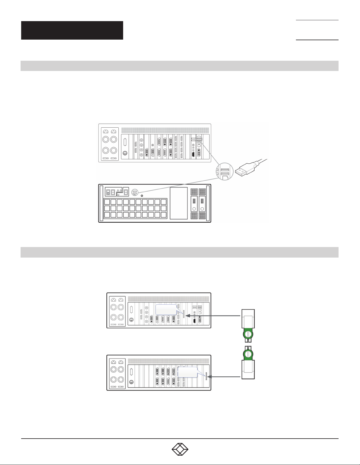
STEP 1: KEYBOARD AND MOUSE
Connect Keyboard and Mouse to convenient USB Ports.
USB Ports are located on both the front and rear panels of the system. If the intention is to mount the Radian Flex wall controller in
a rack, it may be more convenient to use the USB ports on the front for easy access.
(4) external USB 2.0 ports (2 front panel, 2 rear panel)
(2) external USB 3.0 ports (rear panel)
Rear Panel
TECHNICAL
SUPPORT
1. 8 7 7. 8 7 7. 2 2 69
Front Panel
FIGURE 1.
STEP 2: CONNECT EXPANSION CHASSIS (OPTIONAL)
A Radian Flex Expansion Chassis may have been purchased as part of a large video wall system or ordered separately. Connect
the Host Link card in the main system to the Slave Link card in the expansion chassis using the Extension Cable G3. The Extension
Cable G3 is packaged and shipped with the Radian Flex Expansion Chassis.
Host Link
Slave Link
FIGURE 2.
For connecting Optical Expansion products, consult the User Guide located later in this document.
1. 8 77. 8 77. 226 9 BLACKBOX.COM
5
Page 6
NEED HELP?
LEAV E TH E TEC H TO US
LIVE 24/7
QUICK START GUIDE
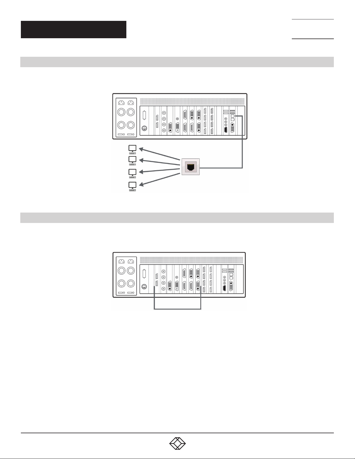
STEP 3: CONNECT TO A NETWORK (OPTIONAL)
If the wall controller is to be used over a network, connect the controller to a network point (cables not supplied) using one of the
LAN connectors on the rear panel.
TECHNICAL
SUPPORT
1. 8 7 7. 8 7 7. 2 2 69
FIGURE 3.
STEP 4: CONNECT INPUT SOURCE
As each wall controller is custom built, the number and type of video inputs will differ from system to system. If you have
purchased a wall controller with video inputs, the input connectors are located on the rear panel as shown in the example below:
Video Input Connectors
FIGURE 4.
Connect the input sources to the relevant video input connectors; cables may be supplied for some inputs, see content list for details.
6
1. 8 77. 8 77. 226 9 BLACKBOX.COM
Page 7
NEED HELP?
LEAV E TH E TEC H TO US
LIVE 24/7
QUICK START GUIDE
TECHNICAL
SUPPORT
1. 8 7 7. 8 7 7. 2 2 69
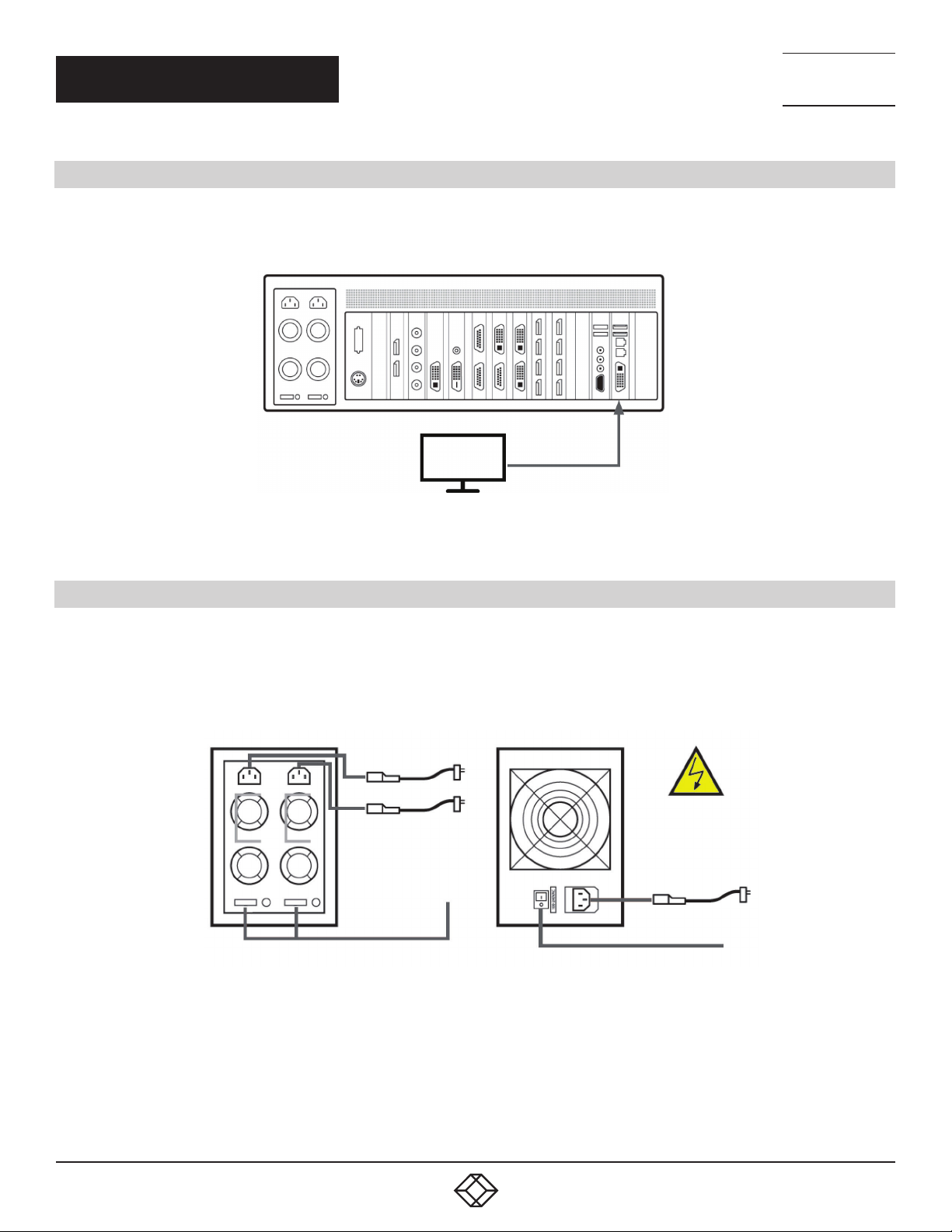
STEP 5: CONNECTING A CONTROL SCREEN
Your wall controller is configured to use a control screen connected to the systems’ internal graphics device before leaving the factory.
Connect the control screen to the motherboard graphics output connector on the rear of the wall controller. A control screen is initially
required to set up the system including the operating system (Windows 10).
VGA or DVI
Control Screen
FIGURE 5.
STEP 6: POWERING THE SYSTEM
Radian Flex wall controllers are supplied with either a Redundant Power Supply Unit (RPSU) or an ATX power supply. An RPSU power
supply requires two power cables and an ATX supply requires one power cable. All power cables are supplied with your wall controller.
1. Connect power cable(s) to the wall controller then plug into a main power supply.
2. Switch on the power supply units.
1
1
2
RPSU Power Switch
2
ATX Power Switch
FIGURE 6.
1. 8 77. 8 77. 226 9 BLACKBOX.COM
7
Page 8
NEED HELP?
LEAV E TH E TEC H TO US
LIVE 24/7
QUICK START GUIDE
3. Switch on the system using the power button on the front panel.
3
FIGURE 7.
NOTE: If you have a Radian Flex Expansion Chassis connected to the main unit (Step 2), the power supply units on the expansion
chassis should be switched on prior to the main wall controller. There is no requirement to switch on the expansion chassis on the
front panel (3).
TECHNICAL
SUPPORT
1. 8 7 7. 8 7 7. 2 2 69
STEP 7: WINDOWS 10 SETUP
Once the system has been built and congured in our factory, the operating system is resealed, and when you switch the system on
for the rst time, the operating system setup begins. You will be prompted to enter information to set up the Windows 10 operating
system.
There is no requirement for users to activate Windows 10, activation is done automatically. An internet connection is required for the
automatic activation.
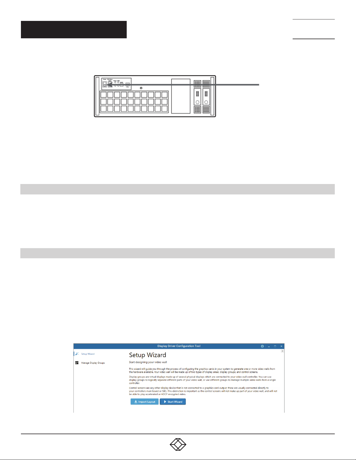
STEP 8: DISPLAY CONFIGURATION
Once the Windows 10 setup is complete, the wall controller will reboot and the control screen will show a Windows desktop
displaying the Display Driver Conguration Tool (DDCT). The DDCT will guide you, step-by-step, through the conguration of the
graphics outputs, enabling you to quickly create one or more video walls.
On the nal stage of the conguration, the DDCT will recommend the optimum way to connect your wall controller to your video wall
displays.
A full description of the DDCT can be found in the User Guide located later in this document.
It is recommended that you carefully read the instructions on each page of the wizard. To begin your wall conguration, click on “Start
Wizard.”
FIGURE 8.
8
1. 8 77. 8 77. 226 9 BLACKBOX.COM
Page 9

QUICK START GUIDE
Select the type of displays being used on your wall:
Displays With Bezels – Monitors, TVs and DLP Cubes
Overlappable Displays – Projectors
LED Displays
NEED HELP?
LEAV E TH E TEC H TO US
LIVE 24/7
TECHNICAL
SUPPORT
1. 8 7 7. 8 7 7. 2 2 69
FIGURE 9.
Click on “Continue.”
The tool will then display a conguration page for the type of display you selected.
FIGURE 10.
1. 8 77. 8 77. 226 9 BLACKBOX.COM
9
Page 10

NEED HELP?
LEAV E TH E TEC H TO US
LIVE 24/7
QUICK START GUIDE
What Types of Displays do you Have?
Use the “Manufacturer” and “Model” drop-down lists to select the displays you are using for your wall. If the wall consists of different
displays, select each one in turn to congure the type of display. The DDCT has an extensive database of displays; however, if your
display is not contained in the list, you can input the details manually by selecting “Create Custom Display.”
We strongly recommend that you take measurements from the display manufacturer’s specications if available.
TECHNICAL
SUPPORT
1. 8 7 7. 8 7 7. 2 2 69
FIGURE 11.
Add Displays
Add Displays is available for displays with bezels or overlappable displays. Use the “Displays Across” and the “Displays Up” to create
your Display Group. Once created, congure the displays using “What Type of Displays Do You Have?” When using overlappable
displays, “Display Overlap” becomes available, enabling you to select a percentage of overlap between displays.
FIGURE 12.
10
1. 8 77. 8 77. 226 9 BLACKBOX.COM
Page 11
QUICK START GUIDE
NEED HELP?
LEAV E TH E TEC H TO US
LIVE 24/7
TECHNICAL
SUPPORT
1. 8 7 7. 8 7 7. 2 2 69
FIGURE 13.
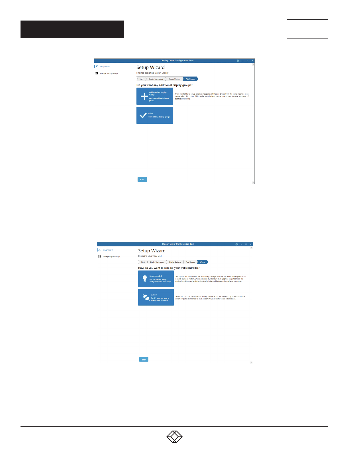
At this stage of the setup, you can choose to create another independent display group from the same system; this would be
considered if one machine will be used to drive a number of separate video walls. See the User Guide section for more details.
If another display group is not required, click on “Finish” and the following page is displayed:
FIGURE 14.
The DDCT can recommend the best wiring conguration for the displays and your system, ensuring the load is balanced
between the graphics hardware. Click on “Recommended” for the optimal conguration for your system.
(If you want to manually wire your system and decide for yourself which output is connected to which display, click on “Custom.”)
1. 8 77. 8 77. 226 9 BLACKBOX.COM
11
Page 12
QUICK START GUIDE
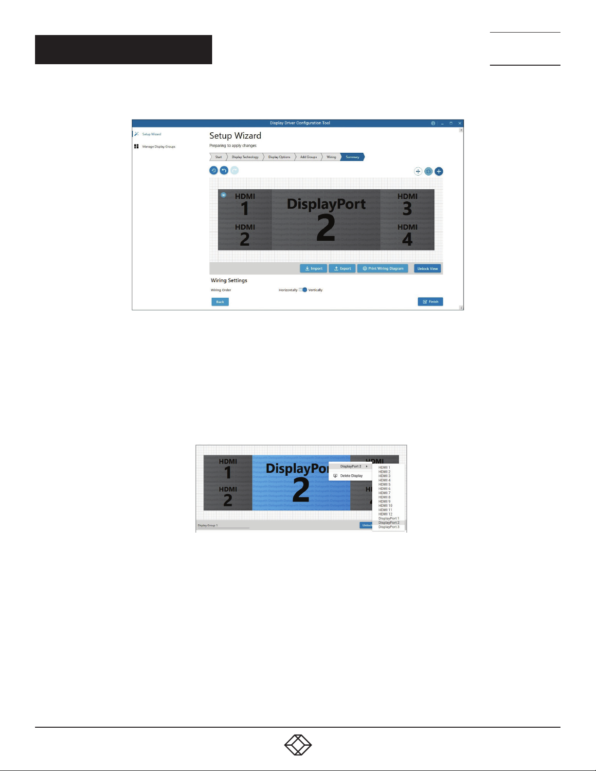
You will be next be presented with the Summary page:
NEED HELP?
LEAV E TH E TEC H TO US
LIVE 24/7
TECHNICAL
SUPPORT
1. 8 7 7. 8 7 7. 2 2 69
FIGURE 15.
If you chose to have the DDCT congure your wiring, this page will display the recommended display connections, as shown above.
Connect each display to the corresponding output connector on the rear of the wall controller.
NOTE: For help, contact Black Box Technical Support at 877-877-2269 or info@blackbox.com for details.
To manually select the outputs, right-click on the display group and select “Edit.” You can then select each individual display and
allocate your preferred output. Right-click on a selected display to reveal the list of outputs available:
+
FIGURE 16.
When all outputs have been allocated by either “Recommended” or “Custom,” click on “Finish.” You will then be prompted to save the
changes to your video wall and restart your system. When restarted, the Windows Desktop will be displayed across the wall.
You can access the conguration tool at anytime if you want to make changes. Right-click on the desktop and select Display Driver
Conguration Tool from the menu.
12
1. 8 77. 8 77. 226 9 BLACKBOX.COM
Page 13
NEED HELP?
LEAV E TH E TEC H TO US
LIVE 24/7
QUICK START GUIDE
TECHNICAL
SUPPORT
1. 8 7 7. 8 7 7. 2 2 69
STEP 9: RADIAN STANDARD VIDEO WALL SOFTWARE
Before opening the Radian Standard Video Wall Software Client interface, you may need to start the Radian Standard Video Wall
Software Server if it does not start automatically. The Server icon is displayed in the System Tray.
Server icon —>
If the Server fails to start automatically, start the Server by clicking on it in the “All Programs” menu. The Radian Standard Video Wall
Software Client will only detect servers that are running.
Start | All Programs | Radian Standard Video Wall Software - Server
Open the Radian Standard Video Wall Software Client
Start | All Programs | Radian Standard Video Wall Software - Client
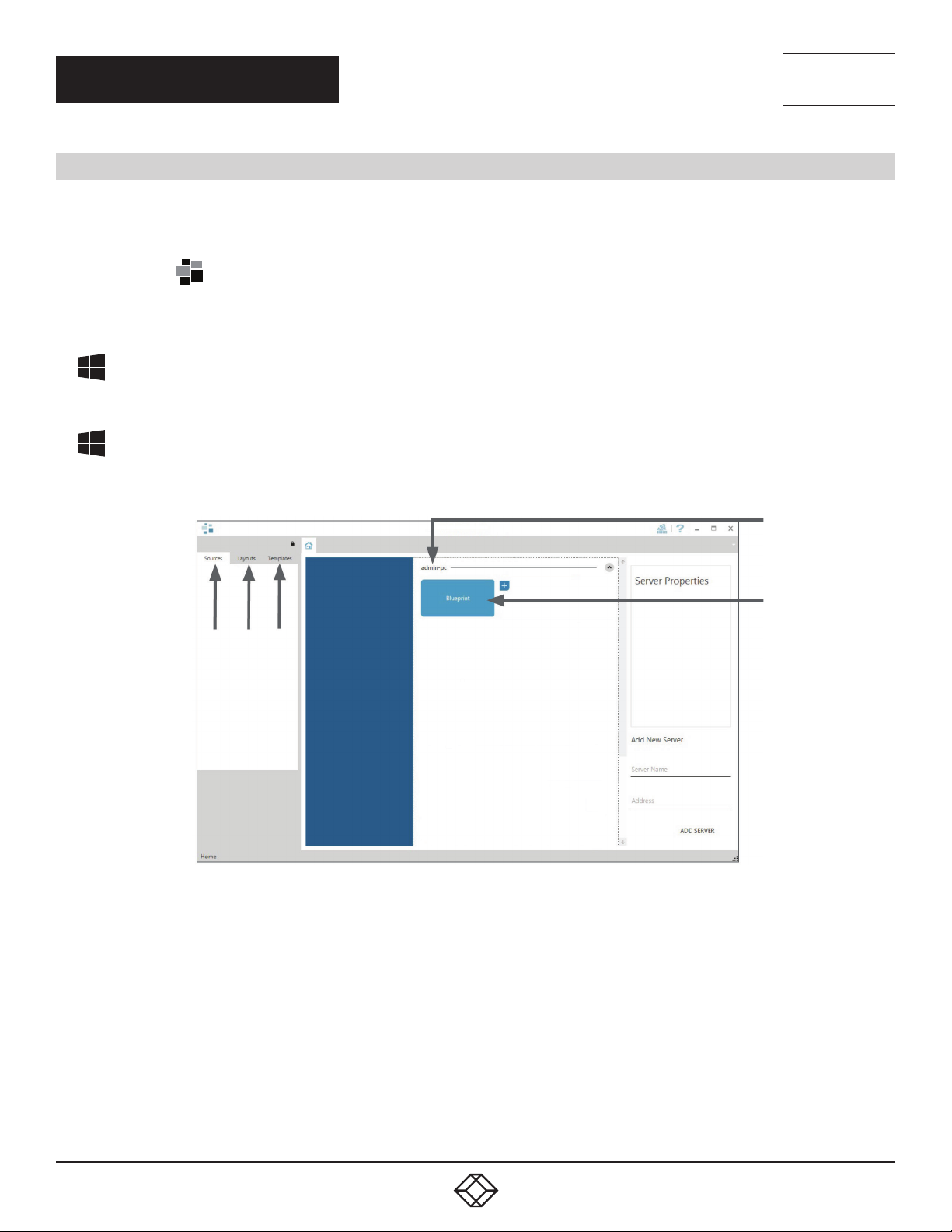
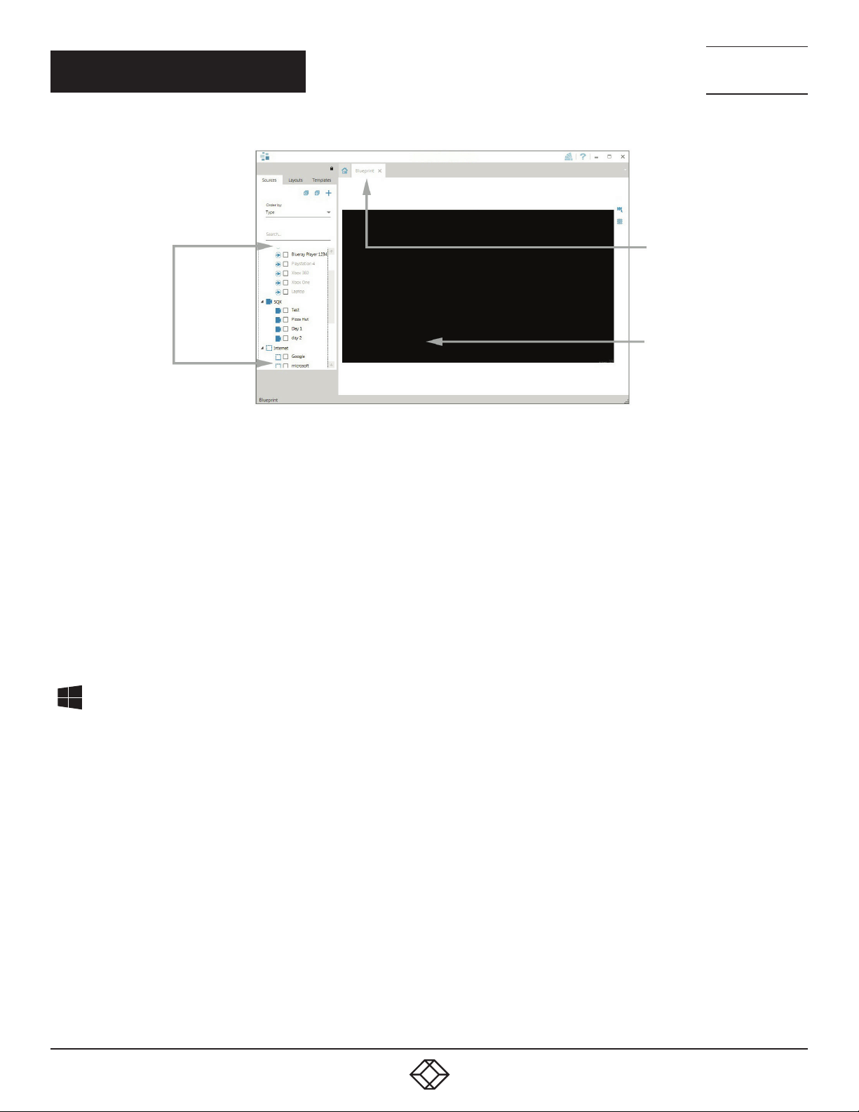
The Radian Standard Video Wall Software - Client
3 4 5
FIGURE 17.
1. Indicates the server you are connected to.
2. A representation of the display wall associated with the server.
1
2
3. Sources Tab - Displaying all the sources connected to the server for use on your display wall.
4. Layouts Tab - Use to save, recall and share display wall layout congurations.
5. Templates Tab - Use templates to assist in the design of specic display wall layouts.
Click on the display wall representation (2) as shown on the previous illustration to open the display wall tab.
1. 8 77. 8 77. 226 9 BLACKBOX.COM
13
Page 14
QUICK START GUIDE
Sources
FIGURE 18.
NEED HELP?
LEAV E TH E TEC H TO US
LIVE 24/7
TECHNICAL
SUPPORT
1. 8 7 7. 8 7 7. 2 2 69
Display Wall
Tab
Display Wall
Representation
When opened, the display wall tab shows a live representation of the physical wall and the sources available to display on it. To place a
source on the video wall, simply click on the required source in the sources tab and drag it onto the display wall representation.
(NOTE: It is not possible to drag Application sources, double-click to open.)
The application help file contains information explaining how multiple sources can be selected, how to use and create templates and how
to save, recall and share layout files.
The Radian Video Wall Software - Security Administration Client (Only Available with Radian Video Wall Software)
A Radian Video Wall Software serial dongle must be inserted into a vacant USB port. If the dongle is removed or swapped, the
Security Client will not open and an error message is displayed, so do not remove the dongle.
If you have purchased Radian Video Wall Software, the license dongle is located in the accessories box.
Start | All Programs | Radian Video Wall Software - Security Administration Client
14
1. 8 77. 8 77. 226 9 BLACKBOX.COM
Page 15
QUICK START GUIDE
NEED HELP?
LEAV E TH E TEC H TO US
LIVE 24/7
TECHNICAL
SUPPORT
1. 8 7 7. 8 7 7. 2 2 69
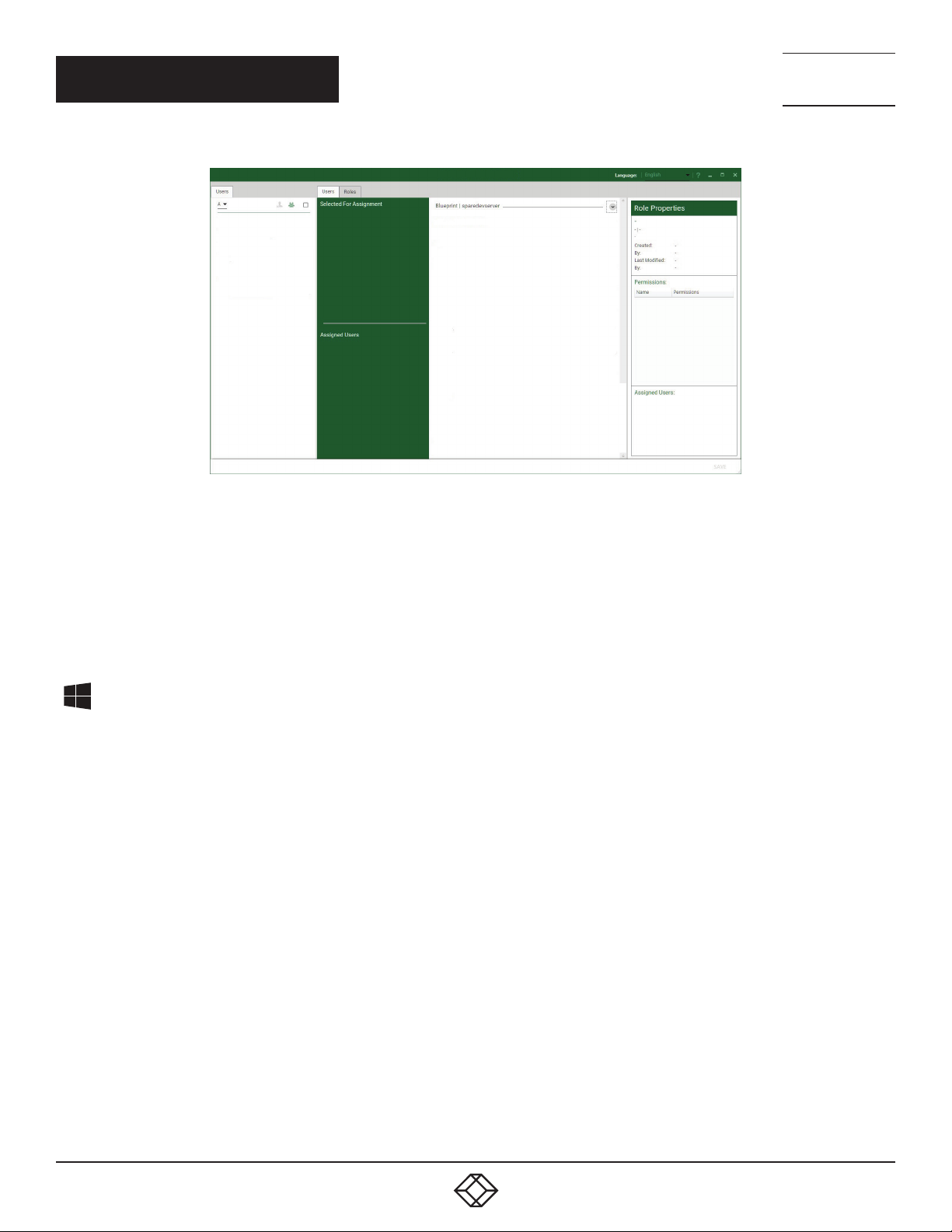
FIGURE 19.
The Radian Video Wall Software - Security Administration Client allows Administrators to assign specic users to roles on a wall-by-wall
basis. For example, a user can be assigned a role allowing unrestricted access on one wall but assigned a role on another wall that only
allows the opening of pre-determined layouts.
Before using Security Client for the rst time, the SecurityOnOff.exe program must be running to enable security protection for the
application. To manually run the SecurityOnOff.exe, make sure you are logged into Windows with Administrator Rights.
Locate and double click on the SecurityOnOff.exe le:
Program Files|Radian Video Wall Software| Security Server|SecurityOnOff
The Radian Video Wall Software Security Application help le contains information on how to:
Import users from the Windows Active Directory into the database
Create and edit roles
Assign permissions to providers, layouts and sources, giving specific roles access to them
Assign roles to walls
1. 8 77. 8 77. 226 9 BLACKBOX.COM
15
Page 16

QUICK START GUIDE
STEP 10: VIDEO WALL MANAGER (OPTIONAL)
Start | All Programs | Video Wall Manager | Video-Wall-Manager-My Computer
NEED HELP?
LEAV E TH E TEC H TO US
LIVE 24/7
TECHNICAL
SUPPORT
1. 8 7 7. 8 7 7. 2 2 69
1
1. The Icons displayed in the application toolbar identify the type of source available to each input.
2. Icons highlighted green indicate an active capture for that particular input.
3. Representation of the control screen if one is being used.
4. Representation of the video wall desktop.
2 3
FIGURE 20.
4
FIGURE 21.
To open a video window, click and drag an active capture into the Radian Video Wall Software application.
Use the Help Menu for a comprehensive guide on the features of the Radian Video Wall Software application.
16
1. 8 77. 8 77. 226 9 BLACKBOX.COM
Page 17
NEED HELP?
LEAV E TH E TEC H TO US
LIVE 24/7
CHAPTER 1: OVERVIEW
1.1 INTRODUCTION
The Radian Flex Video Wall Controller system has been manufactured and tested to the highest standards offering unparalleled
quality and reliability. The aim of this user guide is to assist you through the installation of the system safely and effectively and act
as a reference guide for future use. Do not switch on the system until all the relevant cables have been connected.
1.2 SYS TEM S
The systems covered by this user guide are the Radian Flex 4-, 9-, and 11-slot video wall controllers and expansion chassis ranges.
1.3 HOW THE USER GUIDE IS ORGANIZED
The user guide is broken down into chapters and each chapter into sections. Chapters, sections and pages are numbered
individually.
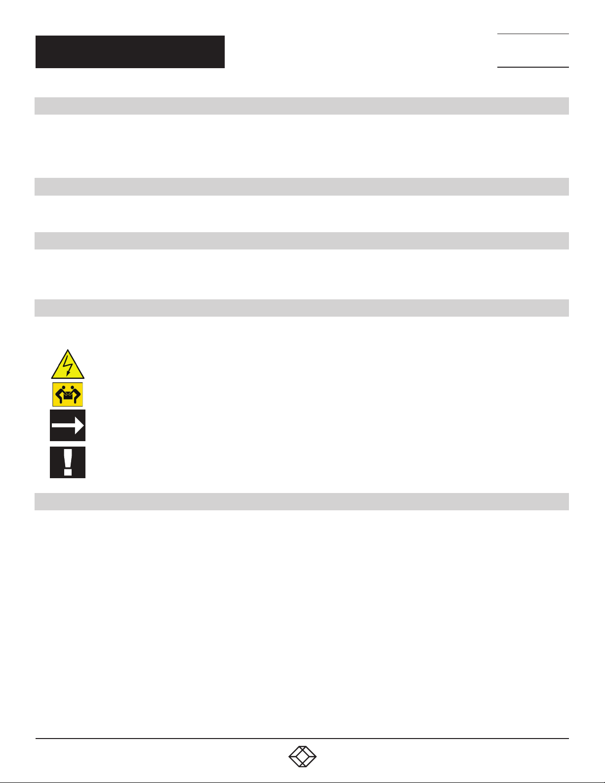
1.4 SYMBOLS
Symbols are used throughout this user guide to assist the user in quickly identifying important safety information and notes.
TECHNICAL
SUPPORT
1. 8 7 7. 8 7 7. 2 2 69
Yellow triangle indicates that failure to observe the instructions could result in injury and/or damage to the system.
Lifting precautions should be considered.
White arrow in a black box indicates a useful tip.
White exclamation mark in a black box indicates important information.
1.5 TERMINOLOGY AND DEFINITIONS
BIOS: Basic Input/Output System: Used during system boot up to initialize and test system hardware and load the operating system.
Each BIOS is specically designed to work with a particular motherboard.
Command Line Interface: Preferred means by advanced users of issuing commands and controlling an application or operating
system. Programs with a Command Line Interface are generally considered easier to automate via scripting.
Control Screen: All systems are shipped with the BIOS congured to boot the system off the onboard graphics device. This output
can then be used as the Control Screen for a typical video wall. The content of the control screen is not displayed on the video wall
desktop and can be used to host the Video Wall Manager application window.
SBC: A Single Board Computer built on a single circuit board. SBCs in the systems are plugged into the PICMG1.3 slot on the 9- and
11-slot backplanes.
SDK: Software Development Kit: A set of software development tools which allows the creation of certain applications.
Radian Standard Video Wall Software (Optional): An optional software application for controlling and managing Video Capture Cards,
IP Camera and third party application windows on a Radian Flex Video Wall Controller. It provides a graphical representation of the
video wall and a toolbar to manipulate all available input sources and applications.
1. 8 77. 8 77. 226 9 BLACKBOX.COM
17
Page 18

NEED HELP?
LEAV E TH E TEC H TO US
LIVE 24/7
CHAPTER 1: OVERVIEW
Radian Video Wall Software Security Administration Client (Optional): The Radian Video Wall Software Security Administration Client
allows Administrators to assign specic users to roles on a wall by wall basis. The Security Administration Client is only available with
Radian Video Wall Software.
Video Wall Controller Software: A software application that enables the user to monitor the temperatures and voltages of system components.
Screen Order: The order in which the screens appear on the display wall.
TECHNICAL
SUPPORT
1. 8 7 7. 8 7 7. 2 2 69
18
1. 8 77. 8 77. 226 9 BLACKBOX.COM
Page 19

NEED HELP?
LEAV E TH E TEC H TO US
LIVE 24/7
CHAPTER 2: SAFETY
TECHNICAL
SUPPORT
1. 8 7 7. 8 7 7. 2 2 69
2.1 SAFETY PRECAUTIONS
To prevent damage to your Black Box product or injury to personnel operating the equipment, please read the following safety
precautions before operation. These instructions should be made available to all those who will use and operate Black Box products.
2.1.1 P OW E R S U P PLY
These products require a main power supply. This power supply must be disconnected when equipment is being upgraded
or relocated.
2.1.2 C A B LE S
Do not expose cables to any liquids; doing so may cause a short circuit which could damage the equipment. Do not place heavy
objects on top of any cables because this can cause damage and possibly lead to exposed live wires.
2.1.3 VENTILATION
All computer equipment should be located in a well ventilated area. All ventilation holes on the computer casing must be kept clear
of any obstruction at all times. Failure to do so will result in the system overheating and damaging your equipment.
2.1.4 WORKING ENVIRONMENT
Locate the equipment in an environment free from dust, moisture and extreme changes in temperature. Place the equipment on a
stable and solid work surface. Do not place liquids (hot/cold drinks, etc.) near the equipment as spillage could cause serious damage.
2.1.5 GAS/FLAMMABLE LIQUIDS
Never use electronic equipment in the presence of gas or any ammable liquid, doing so could result in an explosion or serious re.
2.1.6 SMOKE/UNUSUAL SMELLS
If you notice smoke or unusual smells being emitted from your system, turn off and unplug the system from the power supply.
The system should then be passed to a qualied technician for inspection. Continued operation could result in personal injury
and damage to property.
2.1.7 MAINTENA NCE
Apart from what is detailed in this user guide, maintenance should only be carried out by competent technicians, any Black Box
plug-in cards that are physically damaged should be returned to Black Box for repair using Black Box RMA procedures.
1. 8 77. 8 77. 226 9 BLACKBOX.COM
19
Page 20
NEED HELP?
LEAV E TH E TEC H TO US
LIVE 24/7
CHAPTER 2: SAFETY
2.1.8 REPACEABLE BATTERIES
CAUTION: Risk of explosion if batteries are replaced with an incorrect type. Dispose of used batteries according to the local laws/
regulations and manufacturer’s instructions.
2.2 RACKMOUNT SAFETY INSTRUCTIONS
2.2.1 TEM PE R ATUR E
If Radian Flex Chassis systems are to be installed in a closed or multi-unit rack assembly, the installation should be such that the
amount of air ow required for safe operation of the equipment is not compromised. The operating ambient temperature of the rack
environment should be maintained below 95° F (35° C) under all conditions. Appropriate cooling arrangements should be built into the
cabinet to ensure that this specication is maintained.
TECHNICAL
SUPPORT
1. 8 7 7. 8 7 7. 2 2 69
2.2.2 MECHANICAL LOADING
Mounting of the equipment in the rack should be such that a hazardous condition is not achieved due to uneven mechanical loading.
2.2.3 CIRCUIT OVERLOADING
Consideration should be given to the connection of the equipment to the main supply circuit and the effect that overloading of the
supply might have on any over-current protection or supply wiring. Appropriate consideration of equipment nameplate ratings should
be used.
2.2.4 RELIABLE EARTHING
Reliable earthing of all rack-mounted equipment should be maintained. Particular attention should be given to supply
connections other than direct connections to the branch circuit (e.g. use of power strips).
2.3 UNPACKING AND INITIAL INSPECTION
2.3.1 UNPACKING
The system is heavy; lifting precautions should be considered.
To unpack the system, follow the instructions provided on the outside of the packaging. All packaging materials should be retained
for future transit.
2.3.2 INITIAL INSPECTION
All systems are carefully prepared for shipment and every effort is made to ensure you receive the product in pristine condition.
On receipt, you should carefully inspect the outer packaging for any transit damage, i.e. any signs that the system may have been
dropped, etc.
20
1. 8 77. 8 77. 226 9 BLACKBOX.COM
Page 21

NEED HELP?
LEAV E TH E TEC H TO US
LIVE 24/7
CHAPTER 2: SAFETY
TECHNICAL
SUPPORT
1. 8 7 7. 8 7 7. 2 2 69
Use the packing list enclosed to establish that all the items are present. If any items from the packing list are missing, contact Black
Box Technical Support at 877-877-2269 or info@blackbox.com.
Check the chassis for damage that could have an adverse affect on the operation of the system or could cause injury to the
operator. If there is any physical damage to the power supply unit, for example, damaged power sockets or exposed
wiring, do not connect to a power source, contact Black Box Technical Support at 877-877-2269 or info@blackbox.com.
1. 8 77. 8 77. 226 9 BLACKBOX.COM
21
Page 22
NEED HELP?
LEAV E TH E TEC H TO US
LIVE 24/7
CHAPTER 3: GENERAL
3.1 O VE R VI E W
Black Box Radian Flex systems are powerful video wall controllers, capable of delivering Ultra High Denition video across large,
multi-screen display installations. Use it in a host of environments, from CCTV security suites to sports stadiums, and from military
installations to utility management centers. The Chassis are fully compatible with Radian Flex PCI Express video capture and graphics
cards that offer Ultra High Denition video for storage and display, including the ability to capture HDCP sources without any display
restrictions. Each system has been designed for use in demanding control room environments. Each component has been subjected
to rigorous testing to ensure the highest levels of performance and reliability.
Features include:
High performance and reliability in demanding conditions
Suited for 24/7 applications
Can be operated via a network
PCIe switched fabrics enables systems to be expanded using additional expansion chassis
Video Wall Software (optional) - Display video on the desktop in real time using an array of features
Video Wall Controller Software software (optional) - Provides monitoring of the temperature and voltage sensors on system
components
TECHNICAL
SUPPORT
1. 8 7 7. 8 7 7. 2 2 69
3.2 RADIAN FLEX CHASSIS
TABLE 3-1. CHASSIS MODELS AND FEATURES
Systems Features
4-Slot
Backplane
VWP-FLEX-961 x x x x x
VWP-FLEX-1182 x x x
VWP-FLEX-962X x x x x
VWP-FLEX-1182X x x x x
VWP-FLEX-1182DX x x x x
VWX-2090* x x x
VWX-2110 x x
VWP-FLEX-951 x x x
VWP-FLEX-962 x x x
9-Slot
Backplane
11-Slot
Backplane
SBC 5 SBC 6 SBC 7
Intel®
Core i5
Intel
Core i7
Dual E5®
Core Xeon
Single E3
Intel Core
Xeon
RPSU ATX
* Available with either an RPSU or ATX power supply.
22
1. 8 77. 8 77. 226 9 BLACKBOX.COM
Page 23
CHAPTER 3: GENERAL
3.3 ASSOCIATED INPUT/OUTPUT CARDS AND RELATED PRODUCTS
TABLE 3-2. INPUT/OUTPUT CARDS AND RELATED PRODUCTS
Product Description
VGC-DP-4 and
VGC-DP-4-R2
VCC-STREAM Dedicated IP Streaming decoding card
VCC-HDMI2-2 Two independent HDMI 2.0 capture channels with HDCP 2.2 support
VCC-DP-2 Dual channel, 4K UHD DisplayPort capture card
VCC-SDI-4 Four channel 3G-SDI video capture card
VCC-HD-4-H Quad HDMI video capture card
VCC-SD-HD-A-2,
VCC-SD-HD-3,
VCC-SDI-SD-HD-3-HD
VCC-SD-HD-A-2,
VCC-SD-HD-3,
VCC-SDI-SD-HD-3-SDI
VCC-HD-4 Eight lane PCI Express capture card with four independent DVI-I HD channels
VCC-SD-HD-A-2,
VCC-SD-HD-3,
VCC-SDI-SD-HD-3
Host Link Host link card for expansion systems
Slave Link Slave link card for expansion systems
Extension Cable Copper cable for expansion systems
Quad output DisplayPort graphics card
Four lane PCI Express capture card with 2 x HD DVI-I and 1 SD channels
Four lane PCI Express capture card with 1 x HD DVI-I, SD, SDI channels
Single Channel HD and single channel SD video capture card
NEED HELP?
LEAV E TH E TEC H TO US
LIVE 24/7
TECHNICAL
SUPPORT
1. 8 7 7. 8 7 7. 2 2 69
1. 8 77. 8 77. 226 9 BLACKBOX.COM
23
Page 24
CHAPTER 4: HARDWARE
4.1 C H AS S IS
4.1.1 FRONT
NEED HELP?
LEAV E TH E TEC H TO US
LIVE 24/7
TECHNICAL
SUPPORT
1. 8 7 7. 8 7 7. 2 2 69
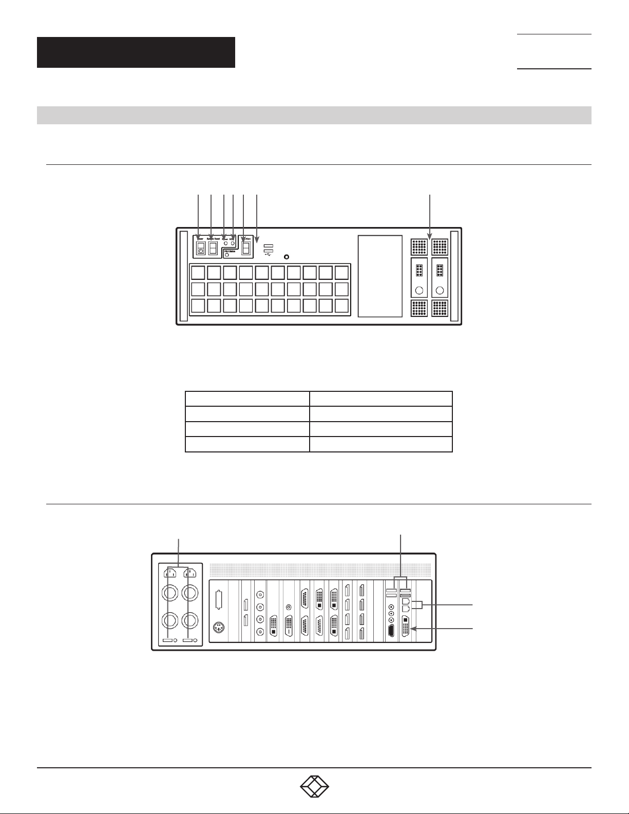
3
1
2
TABLE 4-1. COMPONENTS OF THE CHASSIS FRONT
1 = Power, on-off 5= Reset Button
2= PSU Alarm Reset 6= USB Ports
3= Power LED 7= Removable Hard Drives
4= HDD LED
6
4 5
FIGURE 4-1. FRONT OF THE CHASSIS
7
4.1.2 R E A R
24
R1
R2
R3
R4
FIGURE 4-2. REAR PANEL - RPSU
1. 8 77. 8 77. 226 9 BLACKBOX.COM
Page 25
CHAPTER 4: HARDWARE
R2
NEED HELP?
LEAV E TH E TEC H TO US
LIVE 24/7
TECHNICAL
SUPPORT
1. 8 7 7. 8 7 7. 2 2 69
R3
R1
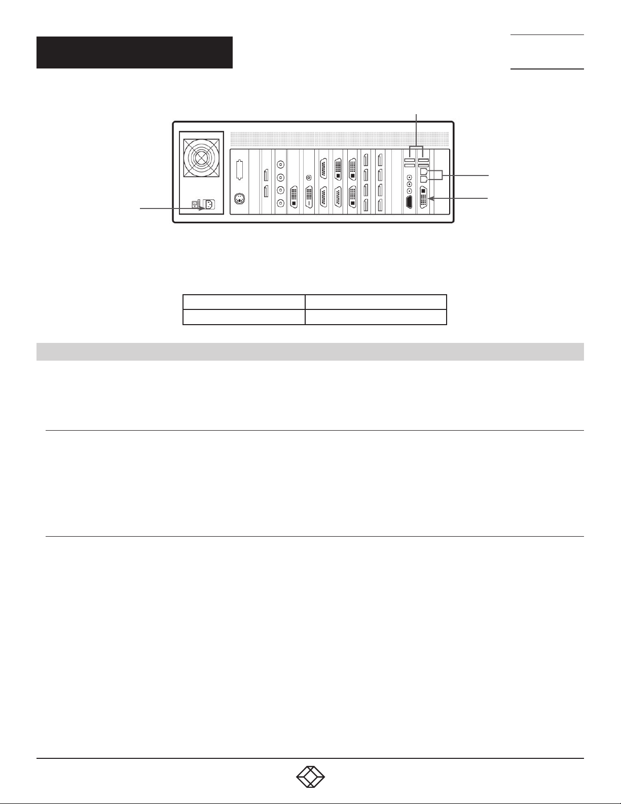
FIGURE 4-3. REAR PANEL - ATX (VWP-FLEX-961 ONLY)
TABLE 4-2. COMPONENTS OF THE CHASSIS REAR
R1= Power Switch R3= Ethernet Ports
R2= USB Ports R4= DVI-I Output
4.2 SINGLE BOARD COMPUTERS (SBCS)
SBCs are for use in the range of video wall controllers providing improvements to the BIOS and a higher performance for Windows
based software applications.
4.2.1 SBC5
The Advantech PCE-9228G2:
An Intel
Used in the VWP-FLEX-1182DX
®
Dual Xeon® E5-2600v3
R4
4.2.2 SBC6
The Portwell 8113-Q170:
An Intel® 7th Gen Kaby Lake Pentium Core i7
Used in the VWP-FLEX-962 and the VWP-FLEX-1182
1. 8 77. 8 77. 226 9 BLACKBOX.COM
25
Page 26

NEED HELP?
LEAV E TH E TEC H TO US
LIVE 24/7
CHAPTER 4: HARDWARE
4.2.3 SBC7
The Portwell 8113-C236:
A Single E3 Xeon processor
Used in the VWP-FLEX-962X and the VWP-FLEX-1182X
4.3 BACKPLANES
The Radian Flex backplanes use advanced PCI Express switches to create a high bandwidth fabric for connecting multiple PCI
Express into a system.
4.3.1 4-SLOT BACKPLANE
4-Slot Backplane
Used in the VWP-FLEX-951
TECHNICAL
SUPPORT
1. 8 7 7. 8 7 7. 2 2 69
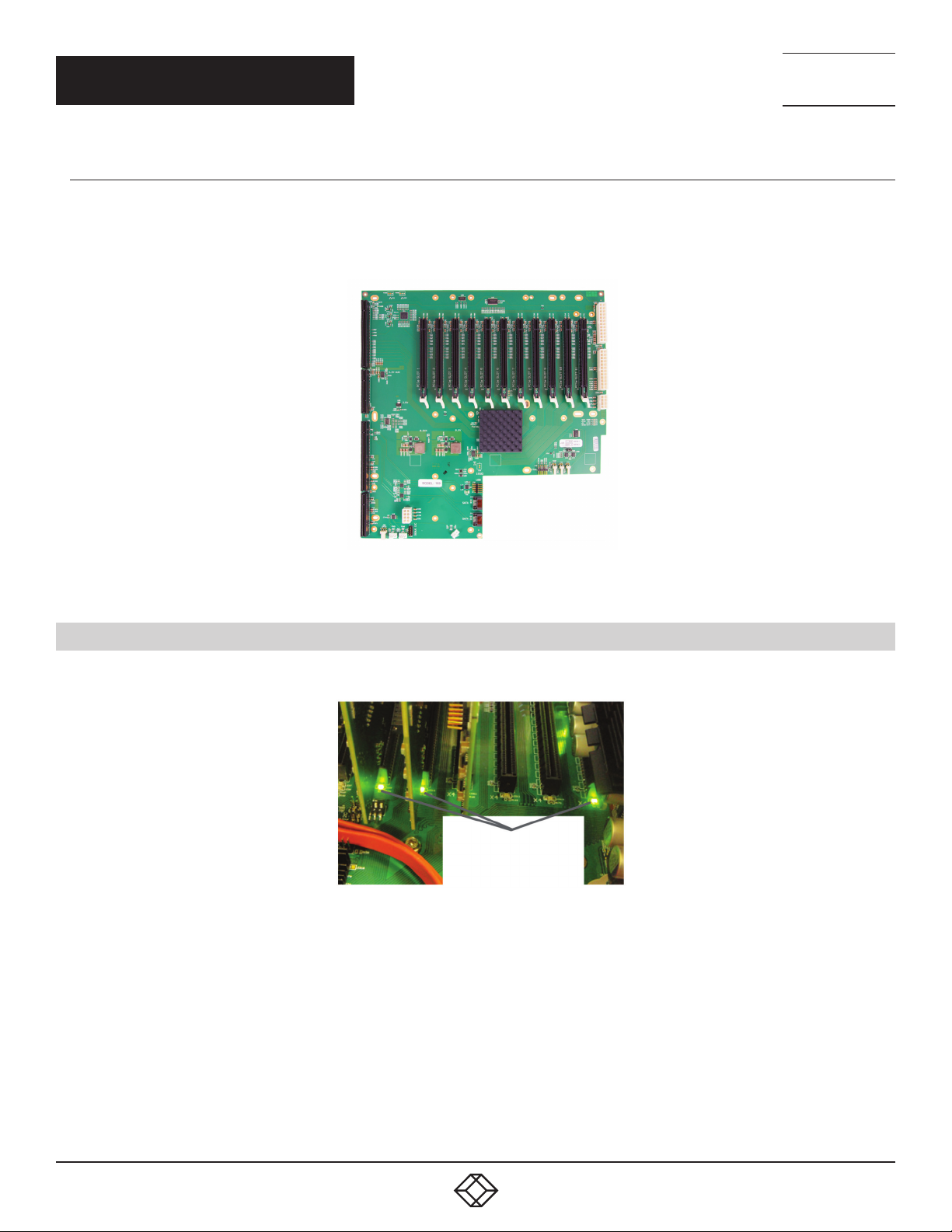
4.3.2 9-SLOT BACKPLANE
Nine slot PCI Express backplane - 8 x 4 lane slots, 1 x 8 lane slot and 1 x PICMG 1.3 slot
Used in the VWP-FLEX-961, VWP-FLEX-962X, and the VWX-2090
FIGURE 4-4. 9-SLOT BACKPLANE
26
1. 8 77. 8 77. 226 9 BLACKBOX.COM
Page 27
CHAPTER 4: HARDWARE
4.3.3 11-SLOT BACKPLANE
Eleven slot PCI Express backplane - 11 x 8 lane PCI Express slot and one PICMG 1.3 slot
Used in the VWP-FLEX-1182, VWP-FLEX-1182X, VWP-FLEX-1182DX and the VWX-2110
NEED HELP?
LEAV E TH E TEC H TO US
LIVE 24/7
TECHNICAL
SUPPORT
1. 8 7 7. 8 7 7. 2 2 69
FIGURE 4-5. 11-SLOT BACKPLANE
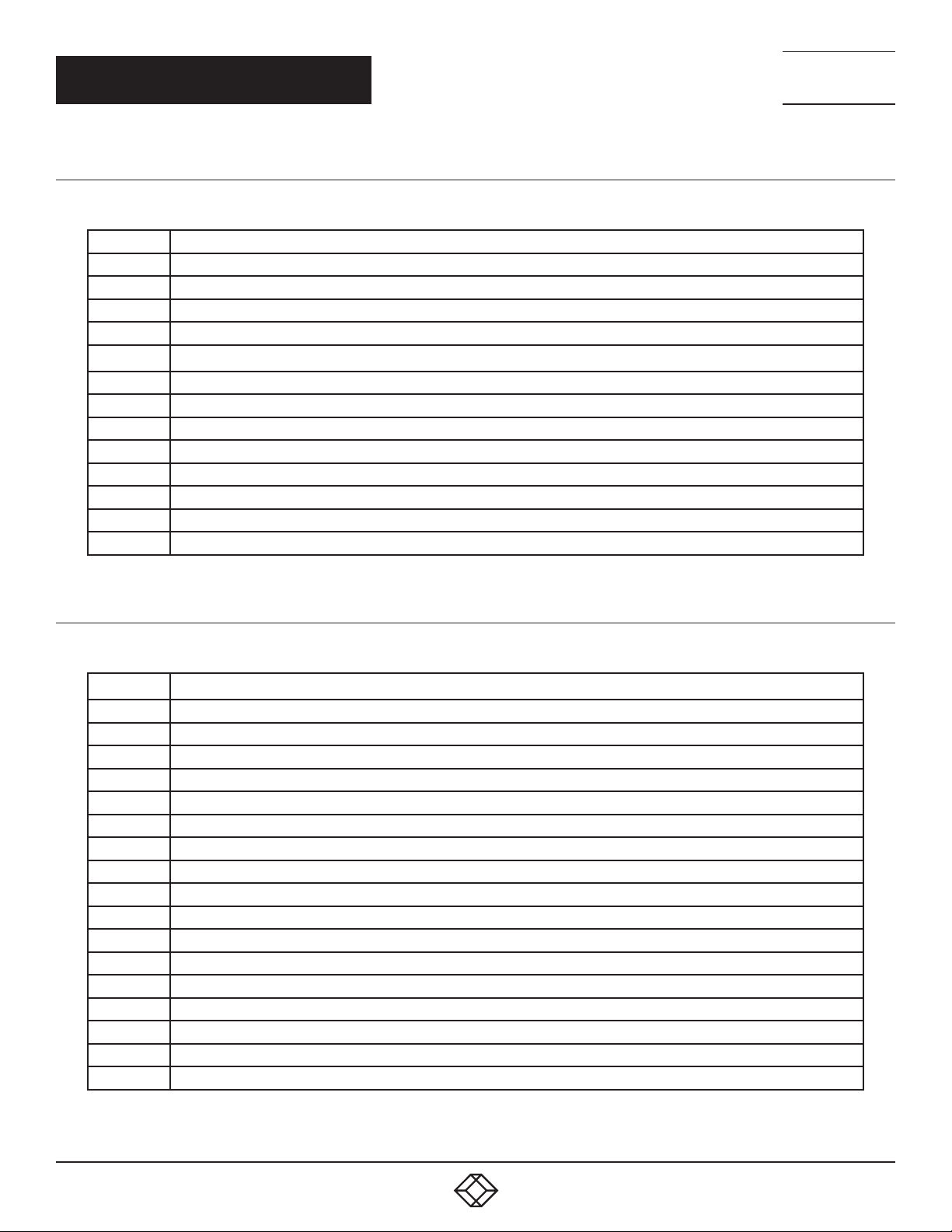
4.4 BACKPLANE LEDS
The 4-slot, 9-slot, and 11-slot backplanes have LEDs tted for each PCI Express slot and the PICMG1.3 slot.
LEDs
FIGURE 4-6. LEDS
1. 8 77. 8 77. 226 9 BLACKBOX.COM
27
Page 28
CHAPTER 4: HARDWARE
4.4.1 9-SLOT BACKPLANE LEDS
TABLE 4-3. 9-SLOT BACKPLANE LEDS
LED1 ON = +5V STANDBY VOLTAGE PRESENT
LED2 ON = +5V SUPPLY PRESENT
LED3 ON = +12V SUPPLY PRESENT
LED4 ON = +3.3V SUPPLY PRESENT
LED5 ON = PICMG LINK SPEED = GEN3, FLASH-FAST = GEN2, FLASH-SLOW = GEN1
LED7 ON = PCIE SLOT 1 LINK SPEED = GEN3, FL ASH-FAST = GEN2, FLASH-SLOW = GEN1
LED9 ON = PCIE SLOT 2 LINK SPEED = GEN3, FLASH-FAST = GEN2, FLASH-SLOW = GEN1
LED10 ON = PCIE SLOT 3 LINK SPEED = GEN3, FLASH-FAST = GEN2, FLASH-SLOW = GEN1
LE D 11 ON = PCIE SLOT 4 LINK SPEED = GEN3, FLASH-FAST = GEN2, FLASH-SLOW = GEN1
LED12 ON = PCIE SLOT 5 LINK SPEED = GEN3, FLASH-FAST = GEN2, FLASH-SLOW = GEN1
LED13 ON = PCIE SLOT 6 LINK SPEED = GEN3, FLASH-FAST = GEN2, FLASH-SLOW = GEN1
LED14 ON = PCIE SLOT 7 LINK SPEED = GEN3, FL ASH-FAST = GEN2, FLASH-SLOW = GEN1
LE D15 ON = PCIE SLOT 8 LINK SPEED = GEN3, FL ASH-FAST = GEN2, FL ASH-SLOW = GEN1
LED16 NOT USED
NEED HELP?
LEAV E TH E TEC H TO US
LIVE 24/7
TECHNICAL
SUPPORT
1. 8 7 7. 8 7 7. 2 2 69
4.4.2 11-SLOT BACKPLANE LEDS
TABLE 4-4. 11-SLOT BACKPLANE LEDS
D1 ON = +12V SUPPLY PRESENT
D2 ON = +3.3V SUPPLY PRESENT
D3 ON = +5V SUPPLY PRESENT
D4 ON = +5V STANDBY SUPPLY PRESENT
D5 ON = PICMG LINK SPEED = G3, FLASH -FAST = G2, FL ASH-SLOW = G1
D6 ON = PCIE SLOT 1 LINK SPEED = G3, FLASH-FAST = G2, FLASH-SLOW = G1
D7 ON = PCIE SLOT 2 LINK SPEED = G3, FLASH-FAST = G2, FLASH-SLOW = G1
D8 ON = PCIE SLOT 3 LINK SPEED = G3, FLASH-FAST = G2, FLASH-SLOW = G1
D9 ON = PCIE SLOT 4 LINK SPEED = G3, FLASH-FAST = G2, FLASH-SLOW = G1
D10 ON = PCIE SLOT 5 LINK SPEED = G3, FLASH-FAST = G2, FLASH-SLOW = G1
D11 ON = PCIE SLOT 6 LINK SPEED = G3, FLASH-FAST = G2, FLASH-SLOW = G1
D12 ON = PCIE SLOT 7 LINK SPEED = G3, FLASH-FAST = G2, FLASH-SLOW = G1
D13 ON = PCIE SLOT 8 LINK SPEED = G3, FLASH-FAST = G2, FLASH-SLOW = G1
D14 ON = PCIE SLOT 9 LINK SPEED = G3, FLASH-FAST = G2, FLASH-SLOW = G1
D15 ON = PCIE SLOT 10 LINK SPEED = G3, FLASH-FAST = G2, FLASH-SLOW = G1
D16 ON = PCIE SLOT 11 LINK SPEED = G3, FLASH-FAST = G2, FLASH-SLOW = G1
D17 ON= PLX FATAL ERROR
D24 ON = PSU FAULT
No LEDs flashing indicates that lane width has not been established. The LEDs will not flash on slots where no cards are installed.
28
1. 8 77. 8 77. 226 9 BLACKBOX.COM
Page 29
NEED HELP?
LEAV E TH E TEC H TO US
LIVE 24/7
CHAPTER 5: CABLING
TECHNICAL
SUPPORT
1. 8 7 7. 8 7 7. 2 2 69
This chapter will cover:
Connecting keyboard and mouse
Connecting an expansion chassis
Connecting to a network
Connecting input sources
Connecting a control screen
Connecting monitors
Connecting power cables
5.1 CONNECTING THE KEYBOARD AND MOUSE
The keyboard and mouse supplied with your system both have a USB interface. Identify vacant USB ports on the front or rear panel
of the chassis and plug them in.
5.2 CONNECTING AN EXPANSION CHASSIS
The Radian Flex expansion chassis are solutions that allow system builders and integrators the exibility to extend a PCIe based PC
or motherboard enabling a larger, distributed system architecture. The optical expansion chassis can be used to create systems with
distances of up to 328 feet (100 meters) between the host PC and the expansion chassis.
The expansion link is created using a combination of Host Link (HLink) and Slave Link (SLink) cards connected together using a cable
or a series of cables (copper or optical). These combined provide a high bandwidth PCI Express link from an upstream host to a
distributed expansion unit.
TABLE 5-1. EXPANSION CHASSIS MODELS
Expansion Chassis Model Backplane Number of available PCIe slots
VWX-2090 9-Slot G3 (Slave Link pre installed) 9
VWX-2110 11-Slot G3 (Slave Link pre installed) 11
CONNECTING THE VWX-2090 AND VWX-2110
If your expansion chassis is supplied as part of a wall controller system, the Host Link card will be pre-installed in the host
machine that contains the SBC. If the expansion chassis has been supplied separate to a host machine, the Host Link card
provided needs to be installed in the host PC.
You are likely to need a at blade and/or a cross head screwdriver for the installation of the Host Link card; it would be useful to have
these in hand before you begin. Power down the PC (including peripherals), switch off at the main power and disconnect all the
cables connected to the computer and expansion chassis. Remove the PC cover. Locate a vacant PCIe slot (x8 on the motherboard
and remove the backing plate (retain all screws) .
Remove the Host Link card from its packaging and secure it rmly into the empty PCIe slot. Screw the bracket to the back panel
of the PC and replace the cover.
1. 8 77. 8 77. 226 9 BLACKBOX.COM
29
Page 30
NEED HELP?
LEAV E TH E TEC H TO US
LIVE 24/7
CHAPTER 5: CABLING
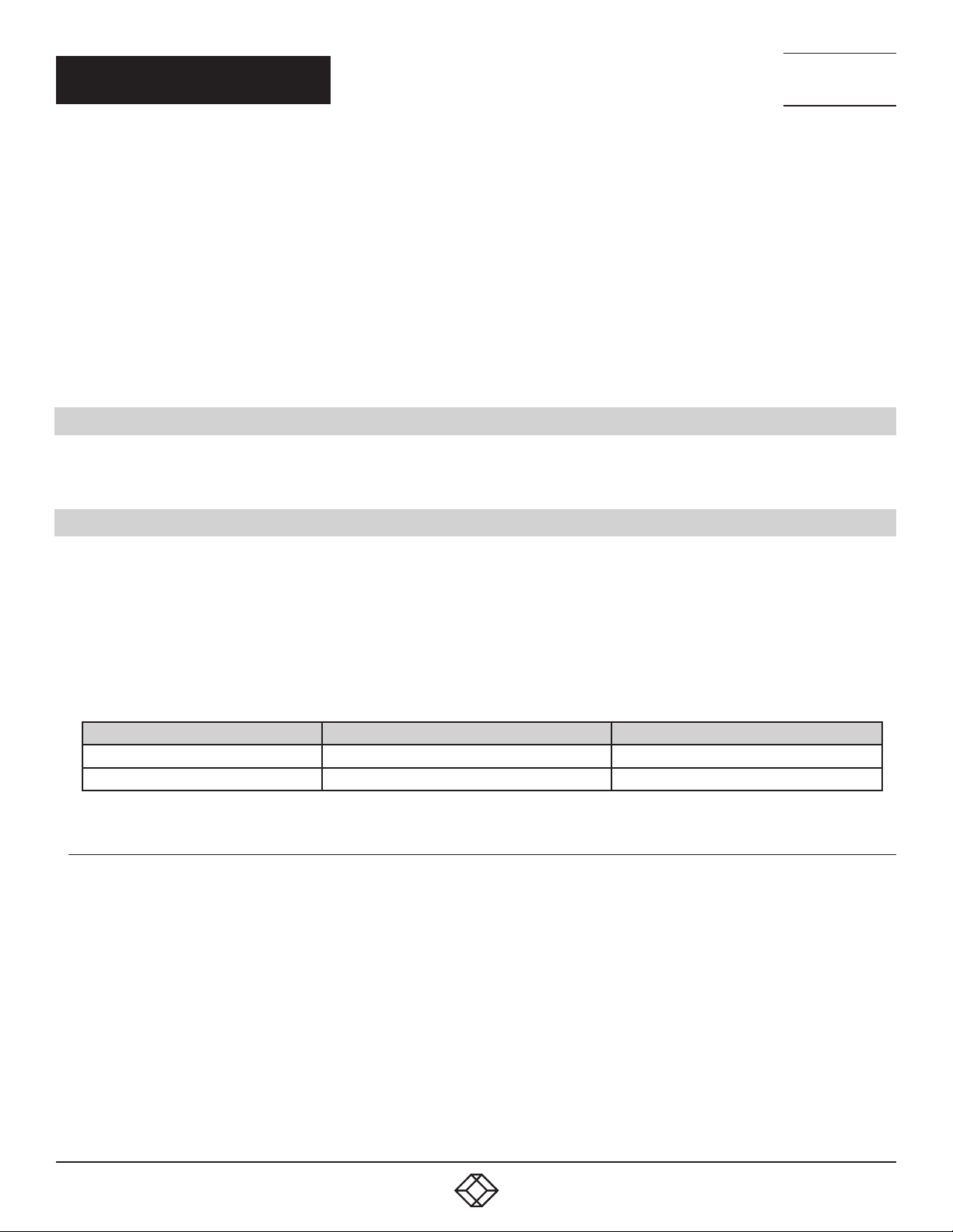
Connect the Host Link and Slave Link using the Extension Cable provided.
FIGURE 5-1.
The correct way to insert the cable is to have the release tab facing away from the card. The rectangular connector needs to be fully
inserted into the card until a denite click can be heard. This locks the cable in place. Failure to lock the connector in place can result
in the Extension Cable becoming separated from the card and the link between chassis being lost.
TECHNICAL
SUPPORT
1. 8 7 7. 8 7 7. 2 2 69
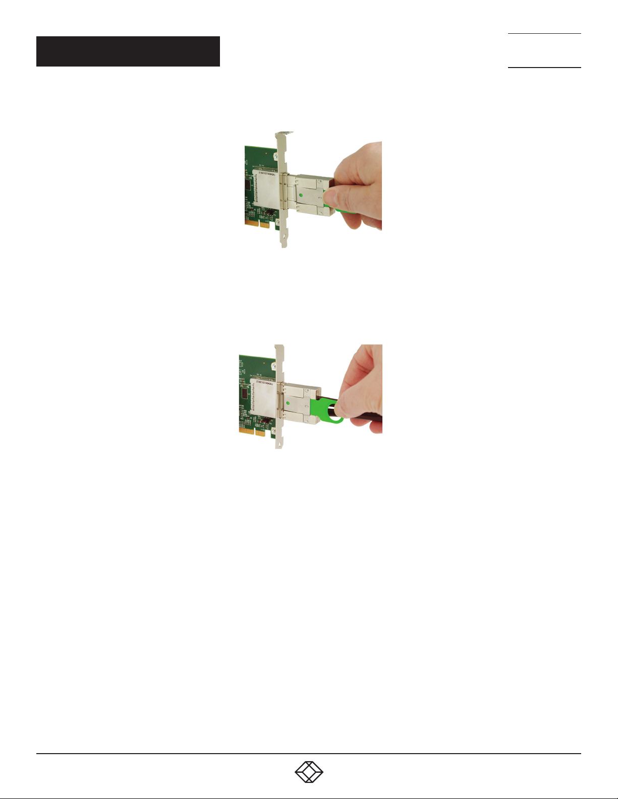
FIGURE 5-2.
To remove the connector, gently pull the ring pull tab to unlock the connector from the card then slide the connector out fully.
Normal copper cable handling precautions should be observed to avoid tight loops or kinks in the extension cable.
If more than one expansion chassis is supplied, ensure the cards are paired correctly by connecting the cards labelled “Link1” together,
the pair labeled “link2” together and so on. If this is not possible, i.e. the expansion chassis are shipped separately and the cards are not
labeled, connect the cards using the extension cables provided and re-install the driver install package to reset the pairings.
30
1. 8 77. 8 77. 226 9 BLACKBOX.COM
Page 31

CHAPTER 5: CABLING
Host System
Expansion
Chassis
NEED HELP?
LEAV E TH E TEC H TO US
LIVE 24/7
TECHNICAL
SUPPORT
1. 8 7 7. 8 7 7. 2 2 69
FIGURE 5-3.
The example above shows the connection of a VWP-FLEX-1182DX to a VWX-2110.
5.3 CONNECTING TO A NETWORK
The optional Video Video Wall Manager software enables the user to operate and manage the video wall display remotely, via a network. The systems have two LAN ports; plug in your network cable (not supplied) to a LAN port and connect the wall controller to the
LAN, as shown below:
FIGURE 5-4.
1. 8 77. 8 77. 226 9 BLACKBOX.COM
31
Page 32

NEED HELP?
LEAV E TH E TEC H TO US
LIVE 24/7
CHAPTER 5: CABLING
NETWORK SECURITY
Note that network ports have a potential vulnerability. If your system is working in a secure environment, you probably don’t need to
worry about unauthorized access to the LAN port. If your system is on a network that is generally accessible, you will probably want
to restrict access to the ports. The Video Wall Manager software application enables you to congure access to the ports using a
network access dialog, see the Video Wall Manager help le (located on the Recovery Media) for more detailed information.
5.4 CONNECTING INPUT SOURCES
As each wall controller is custom built, the number and type of video inputs will differ from system to system. If you have purchased a
wall controller with video inputs, the input connectors are located on the rear panel as shown in the example below:
TECHNICAL
SUPPORT
1. 8 7 7. 8 7 7. 2 2 69
Video Input Connectors
FIGURE 5-5.
Connect the input sources to the relevant video input connectors. Cables may be supplied for some inputs; see the system
content list for details.
32
1. 8 77. 8 77. 226 9 BLACKBOX.COM
Page 33

NEED HELP?
LEAV E TH E TEC H TO US
LIVE 24/7
CHAPTER 5: CABLING
TECHNICAL
SUPPORT
1. 8 7 7. 8 7 7. 2 2 69
CABLE HANDLING
Great care must be taken when connecting cables. Ensure the cable connectors are the correct type for the connector on the cards.
Push the cable connector on squarely, there is no requirement to force the connector in place. Poor cable handling could result in
damaged pins in the cable connector, this in turn could cause serious and irreversible damage to the printed circuit board. Any
damage caused this way is not covered under the warranty.
5.5 CONNECTING A CONTROL SCREEN
Radian Flex Video Wall Controller systems are congured to boot from the onboard graphics device, therefore, there is a requirement
to connect a control screen. The control screen is a standalone DVI-I monitor that is separate from the monitors on the display wall.
The control screen is congured as the Primary monitor in the Windows Display Settings and the display wall is congured as the
Secondary monitor. A control screen is initially required to set up your system, including the operating system (Windows 10) and the
Display Driver Conguration Tool.
Connect the control screen as follows:
VGA or DVI
Control Screen
FIGURE 5-6.
1. 8 77. 8 77. 226 9 BLACKBOX.COM
33
Page 34

CHAPTER 5: CABLING
5.6 CONNECTING POWER CABLES
This section applies to both the RPSU and the ATX powered systems and expansion chassis.
RPSU ATX
NEED HELP?
LEAV E TH E TEC H TO US
LIVE 24/7
TECHNICAL
SUPPORT
1. 8 7 7. 8 7 7. 2 2 69
FIGURE 5-7.
Ensure cable(s) are fully inserted into the power supply sockets on the rear of the wall controller, failure to do so could result in the
cable becoming dislodged and the system inadvertently shutting down.
In systems with an RPSU, both cables must be connected; otherwise, an audible alarm will be triggered when the system is switched
on.
Only use the power cable(s) supplied with your system; for advice on replacements, contact Black Box Technical
Support at 877-877-2269 or info@blackbox.com.
34
1. 8 77. 8 77. 226 9 BLACKBOX.COM
Page 35

NEED HELP?
LEAV E TH E TEC H TO US
LIVE 24/7
CHAPTER 6: OPERATION
TECHNICAL
SUPPORT
1. 8 7 7. 8 7 7. 2 2 69
This chapter will cover:
Switching on
Initial system boot on delivery
Setting up the operating system
Configuring the video wall displays
Opening Video Wall Controller Software
Displaying video captures
6.1 SWITCHING ON
When switching the system on for the rst time, you will need to complete the initial system boot steps as described in Initial System
Boot on Delivery below.
6.1.1 SWITCHING ON THE MAIN SYSTEM
All systems are supplied with either RPSU or ATX power supplies.
Switch on the power supply units (rear panel), ensuring both units on the RPSU are switched on.
RPSU ATX
FIGURE 6-1.
Turn on the main system power switch, located on the front panel.
The BIOS and boot messages will be displayed on the control screen as the system boots. Once the system boot up is complete,
the display wall will open up into a Windows desktop.
1. 8 77. 8 77. 226 9 BLACKBOX.COM
35
Page 36

NEED HELP?
LEAV E TH E TEC H TO US
LIVE 24/7
CHAPTER 6: OPERATION
6.1.2 SWITCHING ON WITH AN EXPANSION CHASSIS
If your system has a VWX-2090 or VWX-2110 expansion chassis, the following procedure should be followed when switching on:
Switch on all the power supply units, ensuring both units on an RPSU system are switched on.
Turn on the main system power switch on the host system, located on the front panel. There is no requirement to turn on the main
power switch on the expansion chassis, because it will be switched on automatically by the host system.
The BIOS and boot messages will be displayed on the control screen as the system boots. Once the system boot up is complete, the
display wall will open up into a Windows desktop.
6.2 INITIAL SYSTEM BOOT ON DELIVERY (WINDOWS 10)
TECHNICAL
SUPPORT
1. 8 7 7. 8 7 7. 2 2 69
Once the system has been congured in the factory, the operating system is resealed, meaning that when switching on the
system for the rst time the operating system setup begins.
You will be prompted to enter information to set up the controller.
6.2.1 SELECT LANGUAGE PACK
You will now be prompted to set up your Windows 10 operating system, starting with selecting the language option you
require. Language selection is the responsibility of the customer and is not part of the system pre conguration prior to
shipment. Windows 10 language settings can be changed using Control Panel/Language. Language packs are available to download
as optional updates. The following languages are pre-installed:
German
English (UK)
English (USA)
Spanish
French
Italian
Netherlands
Polish
Portuguese (Brazilian)
Russian
Simplified Chinese
36
1. 8 77. 8 77. 226 9 BLACKBOX.COM
Page 37

CHAPTER 6: OPERATION
NEED HELP?
LEAV E TH E TEC H TO US
LIVE 24/7
TECHNICAL
SUPPORT
1. 8 7 7. 8 7 7. 2 2 69
FIGURE 6-2.
6.2.2 SELECT COUNTRY AND REGION - WINDOWS 10
Use the drop-down menus to select the country and region, the time zone and currency and the keyboard layout. These
localized settings can be changed if required using the dialog in Control Panel/Region and Language.
FIGURE 6-3.
1. 8 77. 8 77. 226 9 BLACKBOX.COM
37
Page 38

NEED HELP?
LEAV E TH E TEC H TO US
LIVE 24/7
CHAPTER 6: OPERATION
6.2.3 NAMES AND PASSWORD
Next, you will be prompted to create an account for your computer by entering a user name, a computer name and a password.
TECHNICAL
SUPPORT
1. 8 7 7. 8 7 7. 2 2 69
FIGURE 6-4.
We recommend that you only use Internet-standard characters in the computer name. The standard characters are the numbers
0 through to 9, upper and lower-case letters from A through to Z and the hyphen character. Computer names cannot consist entirely
of numbers, contain spaces or use special characters such as: < > ; : “ ?* + = \ | ? ,.
Unlike a Windows 7 system, your Windows 10 system does not require a product key to activate the operating system.
6.2.4 SYSTEM BACKUP
We strongly recommend that you create some form of system recovery media using the MS Windows Backup and Restore Tool once
your system is up and running. This will enable you to restore to factory settings if serious problems occur.
Start | Control Panel | Backup and Restore
6.3 DISPLAY CONFIGURATION TOOL (DDCT)
The DDCT Is a conguration tool designed to guide you through the design and creation of your video wall. The DDCT will guide you,
step by step, through the conguration of the graphics outputs, enabling you to quickly create one or more video walls.
On the nal stage of the conguration, the DDCT will recommend the optimum way to connect your wall controller to your video wall
displays.
Once the Windows Operating System has been congured and rebooted, the DDCT Setup Wizard is displayed on your control screen.
38
1. 8 77. 8 77. 226 9 BLACKBOX.COM
Page 39

CHAPTER 6: OPERATION
(2)
(1)
NEED HELP?
LEAV E TH E TEC H TO US
LIVE 24/7
TECHNICAL
SUPPORT
1. 8 7 7. 8 7 7. 2 2 69
FIGURE 6-5.
We recommend that you read the information on each page carefully.
Click on the “Information Icon” (1) to open a sliding window that gives version details and copyright information.
To begin your wall conguration, click on “Start Wizard” (2). “Import Layout” is covered later.
(3)
(4)
(5)
FIGURE 6-6.
1. 8 77. 8 77. 226 9 BLACKBOX.COM
39
Page 40

CHAPTER 6: OPERATION
6.3.1 DISPLAY TECHNOLOGY
Select the type of displays being used on your wall:
Displays With Bezels – Monitors, TVs and DLP Cubes. (3)
Overlapable Displays – Projectors (4)
LED Displays. (5)
Click on “Continue”.
The tool will then display a conguration page for the type of display you selected:
6.3.1 DISPLAYS WITH BEZELS
NEED HELP?
LEAV E TH E TEC H TO US
LIVE 24/7
TECHNICAL
SUPPORT
1. 8 7 7. 8 7 7. 2 2 69
40
FIGURE 6-7.
1. 8 77. 8 77. 226 9 BLACKBOX.COM
Page 41

CHAPTER 6: OPERATION
6.3.3 OVERLAPPABLE DISPLAYS
NEED HELP?
LEAV E TH E TEC H TO US
LIVE 24/7
TECHNICAL
SUPPORT
1. 8 7 7. 8 7 7. 2 2 69
6.3.4 LED DISPLAYS
FIGURE 6-8.
(6)
(7)
FIGURE 6-9.
1. 8 77. 8 77. 226 9 BLACKBOX.COM
41
Page 42

CHAPTER 6: OPERATION
6.3.5 APPLICATION TOOLS
The application tools enable the user to manipulate the design of the wall. The table below describes the tool functions.
TABLE 6-1. APPLICATION TOOLS
Undo All – Undo all commands made on this page.
Undo – Undo the last command.
Redo – Redo the last command.
Move displays – When selected, move the displays by clicking on and dragging the displays around the representation.
Rotate displays – When selected, click on a display and drag the cursor up or down, left or right to rotate the display.
The display can be rotated 90, 180 or 270 degrees.
Delete displays/Display Groups – Select the displays you wish to remove from the layout then click on the delete button
to delete all those selected.
NEED HELP?
LEAV E TH E TEC H TO US
LIVE 24/7
TECHNICAL
SUPPORT
1. 8 7 7. 8 7 7. 2 2 69
Enable X Axis – Enables the display to be moved from left to right, and right to left.
Enable Y Axis – Enables the display to be moved up and down.
Snap to Grid – When selected, if a display is dragged and released it will snap and position itself to the nearest grid line.
Snap to displays – When selected, if a display is dragged close to another display and released, it will snap and position
itself to the display.
Snap to Guides – When selected, if the display is dragged and released near to the axis of another display, it will position
itself on the same axis.
Show Display Bezels – Select to show or hide the bezels on all the displays in the representation.
Congure Outputs - Available in the Manage Display Group dialog. Select an output and congure its properties.
Add Button- Used to add displays to your group or to create a new group.
Layout Conguration - Used to add LED modules to your group or to create a new group.
Edit - Used to edit a selected Display Group.
Primary Display - Indicates which display within the display group is the primary display/boot screen. If more than one
group is available, the Primary Display can be assigned to either group.
Representation
The representation grid (6) displays the physical arrangement of the wall as it is being created. Displays can be arranged as required by
clicking and dragging them to their required positions using the application tools.
Wall Naming
Click on the edit box (7) to allocate a name to your wall (optional but recommended). This will be used if you choose to export your
layout in the future.
42
1. 8 77. 8 77. 226 9 BLACKBOX.COM
Page 43

NEED HELP?
LEAV E TH E TEC H TO US
LIVE 24/7
CHAPTER 6: OPERATION
TECHNICAL
SUPPORT
1. 8 7 7. 8 7 7. 2 2 69
Unlock View
When unlocked, the wall representation can be dragged to a preferred position using the mouse. Use the mouse wheel to zoom in and
out of the representation.
Select All
Choosing “Select All” enables the user to select all the displays on the representation to apply common attributes to all displays.
6.3.6 WHAT TYPE OF DISPLAYS DO YOU HAVE?
Displays with Bezels and Overlappable Displays
The rst step to creating your wall is to select the type of displays you have. Use the “Manufacturer” and “Model” dropdown lists
to select each display you are using on your wall. The DDCT has an extensive database of displays; however, if your display is not
contained in the list, you can input its details manually by selecting “Create Custom Display.”
FIGURE 6-10.
We strongly recommend that you take measurements from the display manufacturer’s specications if available.
Cables Used
Select the cable types for each monitor. An error message will be displayed if the cable limits are exceeded.
6.3.7 WHAT MODES ARE THE DISPLAYS USING?
Use the drop-down lists to select the “Mode Type” and “Display Mode” for your selected display. Select “Show Display Timings” if you
want to view the display timings.
1. 8 77. 8 77. 226 9 BLACKBOX.COM
43
Page 44

NEED HELP?
LEAV E TH E TEC H TO US
LIVE 24/7
CHAPTER 6: OPERATION
6.3.8 ADD DISPLAYS
Displays with Bezels and Overlappable Displays
Add displays is available for displays with bezels or overlappable displays. It enables you to congure the layout of your wall or display
group. Use the “Displays Across” and the “Displays Up” to create a plan of your layout. Once your layout has been created, you can then
congure the displays using “What Type of Displays Do You Have?” When using overlappable displays, “Display Overlap” becomes
available, enabling you to select a percentage of overlap between displays.
TECHNICAL
SUPPORT
1. 8 7 7. 8 7 7. 2 2 69
FIGURE 6-11.
6.3.9 LAYOUT CONFIGURATION
Layout Conguration is available if LED display technology has been selected.
The layout conguration setting enables you congure the layout of your wall or display group. Use the “Total Modules Across” and the
“Total Modules Up” to create a plan of your layout. Once your layout has been created, then you can congure the modules using “What
display module are you using.”
Allocation Mode
The “Allocation Mode” enables you to select how the distribution of the modules is congured.
Distributed
Creates an even distribution of the modules from all the system outputs. (Recommended)
Unbalanced
Creates an uneven distribution of modules by allocating as many pixels to the rst modules as possible. This creates an unbalanced
load on the system outputs.
Synchronization
Synchronizes all the outputs in the system.
We recommend that you set the synchronization to “On.” Turning “Off” the synchronization can cause tearing when a video source is
displayed; however, it does allow display timings to be edited manually.
44
1. 8 77. 8 77. 226 9 BLACKBOX.COM
Page 45

NEED HELP?
LEAV E TH E TEC H TO US
LIVE 24/7
CHAPTER 6: OPERATION
6.3.10 WHAT DISPLAY MODE ARE YOU USING?
The rst step to creating your wall is to select the type of LED modules you have. Use the “Manufacturer” and “Model” drop-down lists
to select the LED module you are using on your wall. The DDCT has an extensive database of modules; however, if yours is not
contained in the list, you can input its details manually by selecting “Create Custom Module.”
TECHNICAL
SUPPORT
1. 8 7 7. 8 7 7. 2 2 69
FIGURE 6-12.
We strongly recommend that you take measurements from the display manufacturer’s specications if available.
Once a layout has been designed and the type of displays have been selected, you can add the displays to the representation by clicking
on the “Add Displays” icon or “Layout Congurations” if LED modules are being used.
When displayed on the Representation Grid,” each display can be congured separately by clicking on it. Use the tools to position your
displays creating the desired layout. To deselect the display, click on it again.
1. 8 77. 8 77. 226 9 BLACKBOX.COM
45
Page 46

CHAPTER 6: OPERATION
When the display wall or display group has been nalized, click on “Continue” and the following page is displayed:
NEED HELP?
LEAV E TH E TEC H TO US
LIVE 24/7
TECHNICAL
SUPPORT
1. 8 7 7. 8 7 7. 2 2 69
FIGURE 6-13.
6.3.11 ADD GROUPS
At this stage of the setup, you can choose to create another independent display group from the same system. This would be
considered if one machine will be used to drive a number of separate video walls.
Click on the “Add Another Display Group” if you want to add another group of displays. This will return you to the “Display Technology”
page. Note that when creating new display groups, there is no restriction to the type of display technology you can use for each group
you create.
46
1. 8 77. 8 77. 226 9 BLACKBOX.COM
Page 47

CHAPTER 6: OPERATION
If another display group is not required, click on “Finish” and the following page is displayed.
NEED HELP?
LEAV E TH E TEC H TO US
LIVE 24/7
TECHNICAL
SUPPORT
1. 8 7 7. 8 7 7. 2 2 69
FIGURE 6-14.
6.3.12 WIRING
How do you want to wire up your wall controller?
The DDCT can recommend the best wiring conguration for your system, ensuring the load is balanced between the graphics hardware.
Click on “Recommended” for the optimal conguration for your system.
If you want to manually wire your system and decide for yourself which output is connected to which display, click on “Custom.” You will
next be presented with the Summary Page:
FIGURE 6-15.
1. 8 77. 8 77. 226 9 BLACKBOX.COM
47
Page 48

NEED HELP?
LEAV E TH E TEC H TO US
LIVE 24/7
CHAPTER 6: OPERATION
o manually select the outputs, right-click on the display group and select “Edit.” You can then select each individual display and
allocate your preferred output. Right-click on a selected display to reveal the list of outputs available:
FIGURE 6-16.
TECHNICAL
SUPPORT
1. 8 7 7. 8 7 7. 2 2 69
Import
Click on “Import” to import a previously saved layout. Note that if the system the layout is being imported to does not have the hardware
capability to run the layout, the imported layout will be rejected.
Once imported, onto the system, the layout can be edited in the “Manage Display Group” page.
Export
Click on “Export” to generate and export a layout as a .wall le. The layout can then be imported onto another system.
When all outputs have been allocated either “Recommended” or “Custom,” click on “Finish.” You will then be prompted to save the
changes to your video wall and restart your system.
6.3.13 MANAGE DISPLAY GROUPS
Display groups are collections of displays that cover different portions of your video wall. Display groups can be used to separate
different areas of your video wall or use different groups to manage multiple video walls from a single controller.
48
1. 8 77. 8 77. 226 9 BLACKBOX.COM
Page 49

CHAPTER 6: OPERATION
(9)
(10)
NEED HELP?
LEAV E TH E TEC H TO US
LIVE 24/7
TECHNICAL
SUPPORT
1. 8 7 7. 8 7 7. 2 2 69
(8)
FIGURE 6-17.
The “Manage Display Groups” dialog allows you to edit current groups and create new groups. In the example above, two groups have
been created. Hover the mouse over each group (10) to display basic information about the display group:
The group name
Resolution
Details of each output
The “Primary Display” can be assigned to any group by clicking on the icon (9) and toggling between each display group.
To create a new display group, click on the “Create a new display group” icon (8) and the following dialog is displayed.
1. 8 77. 8 77. 226 9 BLACKBOX.COM
49
Page 50

CHAPTER 6: OPERATION
(11)
NEED HELP?
LEAV E TH E TEC H TO US
LIVE 24/7
TECHNICAL
SUPPORT
1. 8 7 7. 8 7 7. 2 2 69
FIGURE 6-18.
Create a new display group by rst selecting the type of technology you will be using for your displays by clicking on the drop-down
list (11). Continue to create your new group layout in the same way you created your initial display group.
6.4 OPENING RADIAN STANDARD VIDEO WALL SOFTWARE (OPTIONAL)
Radian Standard Video Wall Software is an optional video/display wall management software application specically designed
for Radian Flex Video Wall Controllers. Radian Standard Video Wall Software consists of two separate elements that work together
to enable you to control the display wall, the Client (application) and the Server.
The Radian Standard Video Wall Software Start Menu has four options, Radian Standard Video Wall Software Client, Radian
Standard Video Wall Software Server, Radian Standard Video Wall Software Security Server and Radian Standard Video Wall Software
Security Administration Client.
6.4.1 RADIAN STANDARD VIDEO WALL SOFTWARE SERVER
The Radian Standard Video Wall Software Server is used to display IP and application windows. The Server element of Radian
Standard Video Wall Software needs to be installed on the machine to which your video wall is connected. The Server is the machine
that drives your display wall. A Server can be accessed locally or via a network. Radian Standard Video Wall Software will
automatically seek out and display all servers available to you. Each server can run multiple display walls depending on the version
of Radian Standard Video Wall Software you have. Before opening the Client interface, you may need to start the Server manually by
clicking on it in the Programs menu. The Radian Standard Video Wall Software Client will only detect Servers that
are running.
50
Start | All Programs | Radian Standard Video Wall Software | Radian Standard Video Wall Software Server
1. 8 77. 8 77. 226 9 BLACKBOX.COM
Page 51

NEED HELP?
LEAV E TH E TEC H TO US
LIVE 24/7
CHAPTER 6: OPERATION
TECHNICAL
SUPPORT
1. 8 7 7. 8 7 7. 2 2 69
6.4.2 RADIAN STANDARD VIDEO WALL SOFTWARE CLIENT
The Radian Standard Video Wall Software Client should be installed on the machine that has been identied to control the display
wall. This could be any machine on the network including the machine driving the display wall. The application element of Radian
Standard Video Wall Software is used to control the position, size and properties of each window displayed on the Server machine.
The Radian Standard Video Wall Software Client can be installed on systems running up to and including Windows 10 Operating
Systems.
Open the Radian Standard Video Wall Software Client application:
Start | All Programs | Radian Standard Video Wall Software
6.4.3 RADIAN STANDARD VIDEO WALL SOFTWARE - USER INTERFACE
Open the application by selecting Radian Standard Video Wall Software Client and the user interface will be launched.
Tools:
Sources
Layouts
Templates
FIGURE 6-19.
A detailed summary of Radian Standard Video Wall Software features can be found in Chapter 7;
alternatively, a comprehensive help le is available within the application.
1. 8 77. 8 77. 226 9 BLACKBOX.COM
51
Page 52

NEED HELP?
LEAV E TH E TEC H TO US
LIVE 24/7
CHAPTER 6: OPERATION
6.4.4 RADIAN STANDARD VIDEO WALL SOFTWARE SECURITY ADMINISTRATION CLIENT
The Radian Standard Video Wall Software Security Administration Client allows Administrators to assign specic user roles on a
wall by wall basis. Users are assigned Roles based on their Windows login. Roles can be structured to allow only specic tasks to be
carried out on a wall using the Radian Standard Video Wall Software Client. For example, a user can be assigned a role allowing unre-
stricted access on one wall but assigned a role on another wall which only allows the launching of pre-determined layouts.
The application allows you to carry out the following User Rights Management Tasks:
Import users from the Windows Active Directory into the application database
Create and edit roles
Assign permissions to providers, layouts and sources, giving specific roles access to them
Assign Roles to walls
TECHNICAL
SUPPORT
1. 8 7 7. 8 7 7. 2 2 69
6.5 OPENING VIDEO WALL MANAGER
Video Wall Manager are optional video/display wall management software applications specically designed for Radian Flex Wall
Controllers. Both Video Wall Controller Software-red and Video Wall Manager consist of two separate elements that work together to
enable you to control the display wall, the Video Wall Controller Software Application and the Video Wall Controller Software Server.
Start | All Programs | Video Wall Manager
The Video Wall Manager Start Menu offers two methods of opening the application, Video Wall Manager and Video Wall Manager-My
Computer.
6.5.1 VIDEO WALL MANAGER - MY COMPUTER
Video Wall Manager-My Computer refers to your system having both the Video Wall Manager Application and the Video Wall Manager
Server installed. Selecting Video Wall Manager-My Computer will open the Video Wall Manager application window having activated
both the Server and the Application. The application window will display all inputs available in the system.
6.5.2 RADIAN VIDEO WALL CONTROLLER SOFTWARE
Selecting Radian Video Wall Controller Software will launch the application window but will not connect to a Radian Video Wall
Software Server. For more information regarding connecting to a Radian Video Wall Software Server, consult the application help le.
6.6 DISPLAYING VIDEO CAPTURES
Once a connection to a Radian Video Wall Software server has been established, then windows can be created for display on your
video/display wall. Some video formats may not be supported; see Installing video CODECS in the Advanced User Chapter.
Windows can be created using the New menu or the application Toolbar.
52
1. 8 77. 8 77. 226 9 BLACKBOX.COM
Page 53

NEED HELP?
LEAV E TH E TEC H TO US
LIVE 24/7
CHAPTER 6: OPERATION
TECHNICAL
SUPPORT
1. 8 7 7. 8 7 7. 2 2 69
6.6.1 NEW MENU
Displays options for each window type:
Preset Window
Video Capture Cards Window
IP Camera Window
Run an Application
6.6.2 TOOLBAR
The application Toolbar displays a list of the type of windows that can be opened, depending on the hardware you have installed in
your machine.
To open the required inputs:
Select the required input using the cursor and drag to a preferred position on the wall.
Double-click on the required input and the window will open, positioned at the top left of the display wall.
Open multiple inputs by pressing the shift key and clicking the required number of inputs with the mouse.
New Menu
Toolbar
Optional Control Screen
Display Wall
Representation
FIGURE 6-20.
1. 8 77. 8 77. 226 9 BLACKBOX.COM
53
Page 54

NEED HELP?
DL
LEAV E TH E TEC H TO US
LIVE 24/7
CHAPTER 7: SOFTWARE
This chapter will cover:
Video Wall Manager
Radian Standard Video Wall Software
Video Wall Controller Software
Utilities
7.1 VIDEO WALL MANAGER (OPTIONAL)
The optional Video Wall Manager software application (Video Wall Manager) is pre-installed and tested before shipment of your sys-
tem, so no installation of the software is required.
Video Wall Manager displays the desktop of the machine that is being controlled. It allows you to remotely display Video Capture
Cards, IP Camera (Video Wall Manager required) and Application windows across a network on another machine or locally on the
same machine.
TECHNICAL
SUPPORT
1. 8 7 7. 8 7 7. 2 2 69
You can use Video Wall Manager to interactively move, size and position application windows and control Video Capture Cards and IP
Camera
windows by using the Windows Properties sheet. Video Wall Manager also has a guide and grid function to aid the positioning of
windows on the display wall.
Video Wall Manager allows you to save specic wall layouts as .lay les, enabling them to be re-called when required.
There is an area of the application around the desktop where windows can be dragged allowing them to be manipulated
without being displayed on the video/display wall.
7.1.1 ICONS DISPLAYED IN THE VIDEO WALL MANAGER TOOLBAR
The Icons displayed in the application toolbar identify the type of source that is available to each input:
TABLE 7-1. TOOLBAR ICONS
Composite Source
S-Video Source
Analog Source
Component Source
DVI Source
Dual-Link DVI Source
54
DisplayPort Source
SDI/HD-SDI/3G Source
IP Camera Source
If an Icon is displayed with a green surround, this indicates the type of source currently being captured for
that particular input.
1. 8 77. 8 77. 226 9 BLACKBOX.COM
Page 55

NEED HELP?
LEAV E TH E TEC H TO US
LIVE 24/7
CHAPTER 7: SOFTWARE
TECHNICAL
SUPPORT
1. 8 7 7. 8 7 7. 2 2 69
7.1.2 VIDEO WALL CONTROLLER SOFTWARE - FEATURES AND TOOLS
Video Wall Controller Software has a range of advanced features to enable you to manage your video/display wall either locally or
remotely over a network. The following list provides a brief summary of the features and tools contained within the application.
However, all the features and tools are documented in depth in the Video Wall Manager help le, which can be accessed through the
Help menu or by pressing F1 when the application is active.
7.1.3 LAYOUT FILES
Save and recall specic desktop congurations using layout les. Window properties including the position, size and any On Screen
Displays are also saved in layout les.
7.1.4 OFFLINE CONFIGURATION
The Video Wall Controller Software ofine layout editor allows layout les to be created and edited without physically displaying any
windows on the display wall. Video Wall Controller Software can be connected ofine on either the server machine or a machine
without any display wall hardware, for example a laptop.
An ofine connection in Video Wall Controller Software is initiated by opening a conguration le. This le must have been exported
from a server machine and will contain a snapshot of the hardware and software conguration on that machine.
7.1.5 VIDEO CAPTURE CARDS AND IP WINDOW
Control over presenting captured video and IP camera streams on the display wall. Congure window properties including:
Position and size of windows
Aspect ratio enforcement
Exclude window borders and menu bar
Create on-screen display captions
Control capture rate
7.1.6 APPLICATION WINDOWS
Support for controlling applications such as Internet Explorer, Microsoft Powerpoint. Application can be opened direct from the Video
Wall Controller Software Toolbar, through the Command Line Interface or from previously saved layout les.
7.1.7 ON-SCREEN DISPLAY (OSD)
Highly congurable OSD function to overlay bitmaps (not on all types of window) and text over Video Capture Cards and IP Camera
windows. Add descriptions and logos with transparency support and create specic display variables such as frame rates.
1. 8 77. 8 77. 226 9 BLACKBOX.COM
55
Page 56

NEED HELP?
LEAV E TH E TEC H TO US
LIVE 24/7
CHAPTER 7: SOFTWARE
7.1.8 CAROSEL SUPPORT
The Carousel function can automatically cycle through congured lists of different inputs for Video Capture Cards and IP Camera
windows over dened time periods. A double buffering mechanism will automatically start IP Camera streams prior to the carousel
input switch.
7.1.9 SPLIT INTO SUB-WINDOWS
Divide an active Video Capture Cards window into sub-windows. Each sub-window will display a cropped portion of the original Video
Capture Cards window.
7.1.10 A U DI O S U P PO R T
Control digital and analog audio content associated with specic Video Capture Cards windows.
TECHNICAL
SUPPORT
1. 8 7 7. 8 7 7. 2 2 69
7.1.11 COMMAND-LINE INTERFACE
Video Wall Manager comes with a powerful Command Line Interface to enable you to automate almost any operation from opening
layout les, moving windows around the display wall and changing specic input settings.
7.1.12 SUPPORT FOR CRESTRON/AMX CONTROLLERS
Remote Command Line Interface for automation via Crestron/AMX Controllers:
Control the display wall remotely from a Crestron/AMX controller
Access to the full local Command Line Interface
Support for RS-232 (via serial cable) and TELNET (via a local network)
Integrated user interface support to configure and monitor the Remote Command Line
7.2 RADIAN STANDARD VIDEO WALL SOFTWARE (OPTIONAL)
Radian Standard Video Wall Software provides users with the interface required to quickly and effectively manage content that
includes video captures, IP streams and local applications. Users are able to place any input source on any part of the video wall
using a simple drag and drop operation. Precise positioning of each piece of content can be achieved through the mouse and key-
board, or via the template tool.
The Template Tool allows users to not only place their own templates across an entire wall that evenly distributes content, but
Radian Standard Video Wall Software also allows users to apply a template to an individual window so multiple windows can be
grouped together and moved as a single item.
Radian Standard Video Wall Software also introduces a tabbed interface that will allow a single user to seamlessly manage multiple
video walls; a user can see unique walls side by side to ensure things are running smoothly.
56
1. 8 77. 8 77. 226 9 BLACKBOX.COM
Page 57

NEED HELP?
LEAV E TH E TEC H TO US
LIVE 24/7
CHAPTER 7: SOFTWARE
TECHNICAL
SUPPORT
1. 8 7 7. 8 7 7. 2 2 69
Radian Standard Video Wall Software allows multiple walls to be delivered by a single system. Walls in separate areas of a building
can be independently driven from a single location. Multiple walls can be easily set up using the Wall Management functionality and, if
required, each wall can be assigned a unique set of sources or video resources.
Before opening the Client and Security Administration Client interfaces, you may need to start the Radian Standard Video Wall Software
Server by clicking on it in the Programs menu. Starting the Server loads both the Radian Standard Video Wall Software Server and the
Radian Standard Video Wall Software Security Server. The Radian Standard Video Wall Software Client will only detect servers that are
running. The Server icon is displayed in the System Tray.
Server icon ———>
Start | All Programs | Radian Standard Video Wall Software - Server
Opening the Radian Standard Video Wall Software Client
Start | All Programs | Radian Standard Video Wall Software - Client
THE RADIAN STANDARD VIDEO WALL SOFTWARE - USER INTERFACE
3 4 5
FIGURE 7-1. USER INTERFACE
TABLE 7-2. USER INTERFACE CALLOUTS
1 Indicates the server you are connected to
2 A representation of the display wall(s) associated with the server
3 Sources Tab - Displaying all the sources connected to the server for use on the display wall
4 Layouts Tab - Used to save, recall and share display wall layout congurations
5 Templates Tab - Use templates to assist in the design of specic display wall layouts
1
2
1. 8 77. 8 77. 226 9 BLACKBOX.COM
57
Page 58

CHAPTER 7: SOFTWARE
Sources
NEED HELP?
LEAV E TH E TEC H TO US
LIVE 24/7
TECHNICAL
SUPPORT
1. 8 7 7. 8 7 7. 2 2 69
Display Wall
Tab
Display Wall
Representation
FIGURE 7-2.
When opened, the display wall tab shows a live representation of the physical wall and the sources available to display on it. To place a
source on the video wall, simply click on the required source in the sources tab and drag it onto the display wall representation.
The application help file contains information explaining how multiple sources can be selected, how to use and create templates and how
to save, recall and share layout files.
THE RADIAN PRO VIDEO WALL SOFTWARE - SECURITY ADMINISTRATION CLIENT
A Radian Pro Video Wall Software serial dongle must be inserted into a vacant USB port. If the dongle is removed or swapped,
the Security Client will not open and an error message is displayed, so do not remove the dongle.
If you have purchased Radian Pro Video Wall Software, the license dongle can be located in the accessories box.
Start | All Programs | Radian Standard Video Wall Software - Security Administration Client
58
1. 8 77. 8 77. 226 9 BLACKBOX.COM
Page 59

CHAPTER 7: SOFTWARE
NEED HELP?
LEAV E TH E TEC H TO US
LIVE 24/7
TECHNICAL
SUPPORT
1. 8 7 7. 8 7 7. 2 2 69
FIGURE 7-3.
The Radian Standard Video Wall Software - Security Administration Client allows Administrators to assign specific users to roles on a
wall by wall basis. For example, a User can be assigned a role allowing unrestricted access on one wall but assigned a role on another
wall that only allows the opening of pre-determined layouts.
Before using the Security Client for the rst time, run the SecurityOnOff.exe program to enable security protection for the application.
To run the SecurityOnOff.exe, make sure you are logged into Windows with Administrator Rights.
Locate and double click on the SecurityOnOff.exe le:
Program Files (x86) \Radian Standard Video Wall Software\ Security Server\SecurityOnOff
A Radian Video Wall Software serial dongle must be inserted into a vacant USB port. If the dongle is removed or swapped, the Security Client will not open and an error message is displayed, so do not remove the dongle.
The Radian Standard Video Wall Software Security Application help le contains information on how to:
Import users from the Windows Active Directory into the database.
Create and edit roles.
Assign permissions to providers, layouts and sources, giving specific roles access to them.
Assign roles to walls.
1. 8 77. 8 77. 226 9 BLACKBOX.COM
59
Page 60

NEED HELP?
LEAV E TH E TEC H TO US
LIVE 24/7
CHAPTER 7: SOFTWARE
7.3 VIDEO WALL CONTROLLER (OPTIONAL)
The optional Video Wall Controller software application enables you to monitor the temperatures and voltages of the following system
components:
Backplanes
Capture Cards
Streaming Cards
SBC
CPU Cores
Graphics Cards
If any overheating or voltage surge is imminent within the system, the Video Wall Controller application will alert the user via a
pre-congured alarm.
TECHNICAL
SUPPORT
1. 8 7 7. 8 7 7. 2 2 69
When running, the Video Wall Controller Software application can display a transparent oating icon that can be placed anywhere on
the desktop.
Cursor tool tips are available throughout the application offering information and advice. Hover the cursor over different areas of
the application to reveal the tool tips. The application also has a help le to assist you; click on any help button or press F1 on your
keyboard to access the help les.
Left-click the center of the icon to
open the application or right-click
to display the application menu.
Video Wall Controller
Software Icon
FIGURE 7-4.
7.3.1 MONITORING SYSTEM COMPONENTS
Each of the system components listed above have built in temperature and/or voltage sensors that enable the Video Wall Controller
Software application to display any increase or decrease in voltage and temperature. The temperature and voltage ranges are graded
as follows:
Green = Normal operating conditions
Left-click and hold on the border
of the icon to move it around the
desktop.
Amber = An indication that voltages or temperatures are operating outside of normal thresholds and if congured and alarm will
activate.
Red = Indicates that the voltages or temperatures have exceeded the acceptable working thresholds and a system shutdown is
imminent.
60
1. 8 77. 8 77. 226 9 BLACKBOX.COM
Page 61

CHAPTER 7: SOFTWARE
NEED HELP?
LEAV E TH E TEC H TO US
LIVE 24/7
TECHNICAL
SUPPORT
1. 8 7 7. 8 7 7. 2 2 69
FIGURE 7-5.
7.3.2 VIDEO WALL CONTROLLER SOFTWARE APPLICATION WINDOW
The Video Wall Controller Software application window (above) displays the temperature of the capture cards in the system. To view
different components, click on the relevant tabs of the application. Temperatures can be displayed in either degrees Fahrenheit or
degrees Celsius.
7.3.3 CONFIGURING ALARMS
Video Wall Controller Software allows you to congure three types of alarm to warn of impending problems:
System Buzzer - The system buzzer can be congured to determine the amount of time the buzzer will be audible up to a
maximum of 5 seconds. An audio alarm is activated within the system. On some systems, speakers may have to be connected.
Email - If you are not near your system, you can congure an email warning. An email is sent to a nominated email address giving
details of impending problems.
On Screen - Text is displayed on screen to warn of impending problems with the system. The Video Wall Controller Software icon
adopts an amber border when the alarm is issued.
1. 8 77. 8 77. 226 9 BLACKBOX.COM
61
Page 62

NEED HELP?
LEAV E TH E TEC H TO US
LIVE 24/7
CHAPTER 7: SOFTWARE
7.3.4 CURRENT STATUS
At any time, you can check the current status of the monitored components by selecting Show Current Status in Browser from the
Application menu. This will display a browser window, similar to the following:
Summary of the status of
all monitored devices
TECHNICAL
SUPPORT
1. 8 7 7. 8 7 7. 2 2 69
FIGURE 7-6.
7.4 VIDEO CAPTURE CARDS APPLICATION (OPTIONAL)
When purchased separately, capture cards are supplied with a powerful software application for conguring the format of input
sources and displaying the data.
7.4.1 VIDEO STREAMING
DirectShow drivers for WDM Streaming driver supports the following applications, to encode, record and stream video over networks
or the Internet:
Microsoft Media Encoder
VLC
VirtualDub
Any other DirectShow encoding software
For streaming applications, Video Capture Cards can be used with Windows Media Encoder to compress and stream captured video.
To replay the video, use Windows Media Player.
®
Any application compatible with Windows DirectShow technology can use Video Capture Cards because they have built-in WDM
support.
62
1. 8 77. 8 77. 226 9 BLACKBOX.COM
Page 63

CHAPTER 7: SOFTWARE
7.4.2 VIDEO CAPTURE CARDS SOFTWARE CAPABILITIES
Timestamp support for streaming synchronization:
Synchronization of multiple inputs across multiple cards
Synchronize systems using network clock synchronization
For edge blending and other applications
Flexible and congurable EDID Management:
Allows programming of custom EDID parameters for capture cards
Low Input to Output Capture Latency.
NEED HELP?
LEAV E TH E TEC H TO US
LIVE 24/7
TECHNICAL
SUPPORT
1. 8 7 7. 8 7 7. 2 2 69
DMA to third party graphics vendors back and front buffers via Direct3D:
Compatibility with AMD DirectGMA
Compatibility with Nvidia GPUDirect
User Mode lter for source selection:
Enables cropping support in DirectShow on all inputs
Supports Start and Stop trigger interface on all Video Capture Cards inputs
Unied Video Capture Cards Driver:
Multiple cards per system, 16 streams per input
Frame sync and time stamping
DirectShow interface
The RGBEasy API for advanced audio and video control
Fully integrated for use with Video Wall Manager software for video wall applications
7.4.3 MULTISTREAM
The MultiStream feature is available on all capture cards and enables multiple, independently formatted video streams to be set up in
parallel.
Each stream can be formatted completely independently and individual selection of resolution, color space and cropping region can
be set for each stream. This maximizes bandwidth use of the capture card and PCIe interface, and also simplies development tasks
for application developers who do not need to implement video stream reformatting separately.
1. 8 77. 8 77. 226 9 BLACKBOX.COM
63
Page 64

CHAPTER 7: SOFTWARE
7.4.4 VIDEO CAPTURE CARDS APPLICATION OVERVIEW
The application displays the connected source in a window; it has the following features:
Scales the data to fit in the window
Ability to set up sources accurately (settings automatically saved)
Save a single frame to a file in one of the following formats: BMP, JPEG, GIF, TIFF, PNG
Print a single frame
Maintain the aspect ratio of the displayed captured data
Cropping
Display text over the data (on-screen display)
Command line interface
HDCP supported (not supported in SQX encoding)
Help file documenting all features
NEED HELP?
LEAV E TH E TEC H TO US
LIVE 24/7
TECHNICAL
SUPPORT
1. 8 7 7. 8 7 7. 2 2 69
NOTE: The supplied drivers and software require you are using:
Up to and including Windows 10
DVD ROM Drive
7.5 SOFTWARE UTILITIES
Black Box provides a group of software utilities designed to assist you ne tune your system for specic individual system
requirements. All the software utilities can be found on the Recovery Media that was shipped with your system, alternatively, to download the most up-to-date versions, contact Black Box Technical Support at 877-877-2269 or info@blackbox.com.
7.5.1 DESKTOP UTILITY
Used to dene a desktop resolution that can compensate for display bezels or projector overlap.
7.5.2 CUSTOM MADE UTILITY
A utility for dening custom display timings for video modes not available in the display driver or EDID.
7.5.3 MULTI RESOLUTION CONFIGURATION TOOL (MULTIRESCONFIG)
Developed to assist in the design and conguration of a video wall that contains a mixture of multi resolution displays.
64
1. 8 77. 8 77. 226 9 BLACKBOX.COM
Page 65

NEED HELP?
LEAV E TH E TEC H TO US
LIVE 24/7
CHAPTER 7: SOFTWARE
7.5.4 DIAGNOSTIC TOOL (DIAGTOOL)
A diagnostic tool that gathers information to assist in diagnosing problems with hardware and software congurations.
Information is gathered and compressed into a zip le for onward transmission to Black Box Technical Support.
7.5.5 PCICFG TOOL
A diagnostic program that prints out the PCI conguration information. Note, this tool must be run from either a USB or
MSDOS boot disk, it cannot be run from Windows.
7.5.6 SLEEP UTILITY
Designed to generate a pause within a script. This can be used when sequencing the loading of les or application windows.
TECHNICAL
SUPPORT
1. 8 7 7. 8 7 7. 2 2 69
1. 8 77. 8 77. 226 9 BLACKBOX.COM
65
Page 66

NEED HELP?
LEAV E TH E TEC H TO US
LIVE 24/7
CHAPTER 8: TROUBLESHOOTING
8.1 FREQUENTLY ASKED QUESTIONS (FAQS)
8.1.1 I CAN’T SAVE A LAYOUT FILE?
The server does not have a USB License Dongle installed and so Video Wall Manager is working in limited Demo mode.
8.1.2 ACCESS IS DENIED
This message means that the attempt to connect to the server application failed because the authentication information
provided was not acceptable.
One of the following has occurred:
The user name, the password or the machine/domain that you have entered are not correct. Try entering the details again.
TECHNICAL
SUPPORT
1. 8 7 7. 8 7 7. 2 2 69
If the machine to which you are connecting is running Windows XP Service Pack 2 and you have not entered a password, you will
need to change your account so that you have a password.
If the machine you are connecting to is running Windows XP and it is not participating in a domain, you will need to change the
Network Authentication settings on the machine.
8.1.3 RPC SERVER UNAVAILABLE
This message means that the attempt to connect to the server failed.
If you are connecting to My Computer:
Is the server application running?
Did an error occur that prevented the server application from starting the RPC server?
Are you using the correct port name?
If you are connecting across a network:
Has the Video Wall Manager server been activated?
When Video Wall Manager is installed on the server, a serial number must be entered to enable the networking features.
Is the Video Wall Manager server congured for network access?
Is the server application running?
Did an error occur that prevented the server application starting the RPC server?
Are you using the correct port?
If a connection is possible with the Video Wall Manager application either remotely or locally, you can use the Server Application
Manager dialog to nd out if the server application has been installed, is running and which port and port name it is using and if an
error occurred. In the Video Wall Manager application, go to the Congure menu and select Server Applications.
66
1. 8 77. 8 77. 226 9 BLACKBOX.COM
Page 67

NEED HELP?
LEAV E TH E TEC H TO US
LIVE 24/7
CHAPTER 8: TROUBLESHOOTING
If a connection is not possible with the Video Wall Manager application, you will need to look at the application event viewer on the
Video Wall Manager Server.
8.1.4 THE ENDPOINT IS A DUPLICATE
This error message suggests that an attempt to open a communication port failed because it is already in use.
If the Video Wall Manager server has not been activated or the networking has been disabled in the Video Wall Manager Administra-
tor dialog or Video Wall Manager has not been activated, the problem is with the port name.
If networking is enabled, the problem could be with either the port number or the port name.
You can nd out the port number and the port name that the server application is using through the Server Application Manager
dialog or the application event viewer.
You can nd out which port numbers are in use on a machine with the netstat command. There is no way to nd out which port
names are in use.
TECHNICAL
SUPPORT
1. 8 7 7. 8 7 7. 2 2 69
Use Video Wall Manager | Congure Menu | Server Application Manager to change the port number and/or port name and restart the
server application.
8.1.5 THE REMOTE PROCEDURE CALL FAILED AND DID NOT EXECUTE
This is displayed when trying to contact a server application that has been stopped after it had been connected to successfully. Go to
the Server Application Manager dialog and start the server application again.
8.1.6 CHANGING SCREEN RESOLUTION
Before making any changes to the resolution, we recommend that you stop the Video Capture Cards server beforehand. This can be
done using Video Wall Manager | Congure Menu | Server Application Manager.
The servers retain resources on the graphics card, which may not be available if the resolution is changed.
8.1.7 HOW DO I CONNECT A REMOTE COMMAND CONTROLLER VIA RS-232 OR IP TELNET?
Support for RS-232 and IP remote control of machines is provided through our Video Wall Manager software. This package includes
a “remote command line interface” that can be used to select and congure the required method of control. This can be accessed under the ‘“Congure->Remote Command Line” menu option while Video Wall Manager is connected to the server. Once congured, the
Video Wall Manager program does not need to remain open and the system will process remote commands until the conguration is
changed.
To use the remote command line, you must rst select the required method of control via the “Active Server” drop-down list in the “remote command line” dialog. This allows you to select between ‘“Com Port Command Line Interface” (RS-232) and “Telnet Command
Line Interface” (IP network based control). Once a server has been selected, its settings can be congured by pressing the “Settings”
button and it must also be enabled via the “Enabled” checkbox; the server specic settings include options such as ports and transmission speed. Once the selected server has been activated, then the “Status” on the “Remote Command Line” dialog should change
to “Connected.” At this point the software should be ready to receive remote commands and the Video Wall Manager software can
then be closed.
1. 8 77. 8 77. 226 9 BLACKBOX.COM
67
Page 68

NEED HELP?
LEAV E TH E TEC H TO US
LIVE 24/7
CHAPTER 8: TROUBLESHOOTING
RS-232 and Telnet commands can be sent by any suitable remote device, including Crestron Controllers or PCs. Note that we do not
provide any client software or support for the conguration or usage of these remote devices themselves, though.
The commands sent to the controller via the remote command line interface should be in the format of Video Wall Manager’s local
command line interface. The command usage includes the ability to open and close layout les, manipulate individual windows
properties and to change capture sources. These commands, which are detailed in the help le topic “Command Line Interface,” can
be tested by executing them locally on the server machine via the Windows command prompt CMD.EXE. When using the “Com Port
Command Line,” each command will be executed when a carriage return or line feed character is encountered. For Telnet, a carriage
return immediately followed by a line feed is used to signify that the command should be executed. When testing usage of the remote
command line, the “Monitor” window in the “Remote Command Line’” dialog will display all commands as they are received.
Full information on usage of the Remote command line interface can be found in the Video Wall Manager help le by either
searching for “remote command line” or pressing the “Help” button on the “Remote Command Line” dialog itself. Note that Radian
Standard Video Wall Software only supports Telnet.
8.1.8 WHEN I RECALL A FIREFOX OR CHROME PAGE, THE WINDOW IS NOT IN PLACE?
TECHNICAL
SUPPORT
1. 8 7 7. 8 7 7. 2 2 69
Video Wall Manager only supports Internet Explorer. Full functionality is not available using any other web browser.
All the cards in your system are driven together to display a single, virtual desktop across multiple screens. Users should be aware
that although error code 43 is reported, this is normal operation and there are no faults with the cards installed in your system.
8.2 TECHNICAL SUPPORT
8.2.1 CONTACTING BLACK BOX
If you determine that your Radian Flex is malfunctioning, do not attempt to alter or repair the unit. It contains no user-serviceable
parts. Contact Black Box Technical Support at 877-877-2269 or info@blackbox.com.
Before you do, make a record of the history of the problem. We will be able to provide more efcient and accurate assistance if you
have a complete description, including:
the nature and duration of the problem.
when the problem occurs.
the components involved in the problem.
any particular application that, when used, appears to create the problem or make it worse.
8.2.2 SHIPPING AND PACKAGING
If you need to transport or ship your Radian Flex:
Package it carefully. We recommend that you use the original container.
If you are returning the unit, make sure you include everything you received with it. Before you ship for return or repair, contact Black
Box to get a Return Authorization (RA) number.
68
1. 8 77. 8 77. 226 9 BLACKBOX.COM
Page 69

NEED HELP?
LEAV E TH E TEC H TO US
LIVE 24/7
CHAPTER 9: MAINTENANCE
9.1 FILTER MAINTENANCE
The system lter is an integral part of the wall controller and as such it needs to be maintained correctly. Failure to maintain the lter
can result in the system overheating and causing it to fail. In normal operating conditions, the lter should be removed and cleaned
every 3 months. However, this 3 month period is a guide only and it can be increased to every 6 months or decreased to one month
depending on the levels of dust in the environment the system is operating in.
We recommend that you check the condition of the lter at regular intervals.
The lter can be removed and cleaned while the system is in operation, system shutdown is not necessary.
NOTE: Failure to maintain the system lter could result in damage to your system and invalidate the warranty.
9.1.1 REMOVE THE FILTER
Open the front panel door and locate the lter housing screw, remove the screw and lift the lter housing away from the front panel.
TECHNICAL
SUPPORT
1. 8 7 7. 8 7 7. 2 2 69
Filter Housing Screw
Filter
FIGURE 9-1.
Remove the lter from the housing and shake it to remove any dust particles, this should not be done in close proximity to the system
to avoid dust ingress. Ideally, the lter should be cleaned using a vacuum cleaner.
For advice on replacement lters, contact Black Box Technical Support at 877-877-2269 or info@blackbox.com.
NOTE: The lter should never be immersed in water or any other cleaning liquid.
Filter Housing
1. 8 77. 8 77. 226 9 BLACKBOX.COM
69
Page 70

CHAPTER 10: SPECIFICATIONS
This chapter will cover:
Technical drawings of the chassis
Technical specification of the VWP-FLEX-961, VSN982, VWP-FLEX-962X and VWP-FLEX-1182X
Technical specification of the VWX-2090
Technical specification of the VWX-2110
Technical specification of the 9-slot G3 backplane
Technical specification of the 11-slot G3 backplane
10.1 TECHNICAL DRAWINGS
NEED HELP?
LEAV E TH E TEC H TO US
LIVE 24/7
TECHNICAL
SUPPORT
1. 8 7 7. 8 7 7. 2 2 69
427.00
488.80
443.00
482.60
17 7.0 0
70
FIGURE 10-1. DIMENSIONAL DIAGRAM
1. 8 77. 8 77. 226 9 BLACKBOX.COM
Page 71

NEED HELP?
LEAV E TH E TEC H TO US
LIVE 24/7
CHAPTER 10: SPECIFICATIONS
TECHNICAL
SUPPORT
1. 8 7 7. 8 7 7. 2 2 69
10.2 TECHNICAL SPECIFICATIONS - VWP-FLEX-961, VWP-FLEX-962/VWP-FLEX-962X
FIGURE 10-1.
19” 4U Industrial PC chassis
Dimensions (approx) Length 500 mm (incl handles), Height 177 mm, Width 481 mm (incl mounting brackets)
SBC6 - Supports an Intel Core i7 processor (VWP-FLEX-961, VWP-FLEX-962)
SBC7 - Supports Single E3 Intel Core Xeon processors (VWP-FLEX-962X)
16 GB DDR2 1600 DDR3 non-EEC registered system memory. 32 GB available on request. (VWP-FLEX-961, VWP-FLEX-962)
32 GB DDR2 1600 DDR3 non-EEC registered system memory (VWP-FLEX-962X)
64 GB DDR2 1600 DDR3 non-EEC registered system memory.
Express9-G3 PCIe back plane providing 1 x8 lane slot and 8 x4 lane slots
Two 240GB removable SSD hard drives, upgrade option of 480 GB SSD.
Ethernet ports -Dual 10Base-T/ 100Base-TX/ 1000 BaseT
On-board Graphics - DVI-I output for VWP-FLEX-961, VWP-FLEX-962/VWP-FLEX-962X. (Used as a control screen)
RS-232 - For control
USB - 2 x 3.0 (back panel) 6 x 2.0 2 front, 2 back, (2 internal - for security dongles)
500 Watt ATX (VWP-FLEX-961, VWP-FLEX-962 0nly)
600 Watt Hot Swappable RPSU (VWP-FLEX-961, VWP-FLEX-962/VWP-FLEX-962X)
Noise - 48.6 dB (A) up to 67.9 db (A); Dependent on system conguration and ambient temperature
Triple cooling fans with removable air lter
Includes keyboard and mouse
Windows 10 LTSB
Operating temperature: 32 to 95° F (0 to 35° C)
Weight - 19 to 25 kg, Shipping Weight - 30 to 33 kg
Compliance - FCC/CE/RoHS/UL/CCC
1. 8 77. 8 77. 226 9 BLACKBOX.COM
71
Page 72

NEED HELP?
LEAV E TH E TEC H TO US
LIVE 24/7
CHAPTER 10: SPECIFICATIONS
10.3 TECHNICAL SPECIFICATIONS - VWP-FLEX-1182/VWP-FLEX-1182X/VWP-FLEX-1182DX
FIGURE 10-2.
19” 4U Industrial PC chassis
Dimensions (approx) Length 500 mm (incl handles, Height 177 mm, Width 481 mm (incl mounting brackets)
SBC5 - Supports an Intel Dual E5 Xeon Processor (VWP-FLEX-1182DX)
SBC6 - Supports an Intel Core i7 processor (VWP-FLEX-1182)
SBC7 - Supports Single E3 Intel Core Xeon processors (VWP-FLEX-1182X)
16 GB DDR2 1600 DDR3 non-EEC registered system memory. 32 GB available on request. (VWP-FLEX-1182)
32 GB DDR2 1600 DDR3 non-EEC registered system memory (VWP-FLEX-1182X)
64 GB DDR2 1600 DDR3 non-EEC registered system memory.
128 GB DDR2 1600 DDR3 non-EEC registered system memory. (Option available for VWP-FLEX1182DX only)
TECHNICAL
SUPPORT
1. 8 7 7. 8 7 7. 2 2 69
Express11-G3 PCIe back plane providing 11 x8 lane slots
Two 240 GB removable SSD hard drives, upgrade option of 480 GB SSD.
Ethernet ports -Dual 10BASE-T/100BASE-TX/1000BASE-T
On-board Graphics - DVI-I output enabling connection to DVI/VGA using the cable provided. Can be used as a control screen
(Only a VGA connector available on the VWP-FLEX-1182DX).
RS-232 - For control
USB - (2) 3.0 (back panel) (2) 2.0 (2) front, (2) back, ([2] internal - for security dongles)
800 Watt RPSU Dual Redundant
Noise - 48.6 dB(A) up to 67.9 db(A); Dependent on system conguration and ambient temperature
Triple cooling fans with removable air lter
Includes keyboard and mouse
Windows® 10 LTSB
Operating Temperature: 32 to 95° F (0 to 35° C)
72
Compliance - FCC/CE/RoHS/UL/CCC
1. 8 77. 8 77. 226 9 BLACKBOX.COM
Page 73

CHAPTER 10: SPECIFICATIONS
10.4 TECHNICAL SPECIFICATIONS - VWX-2090
FIGURE 10-3.
9-slot G3 PCIe backplane providing 1 x 8 lane slot and 8 x 4 lane slots
600 W Redundant PSU or 500 W ATX
Dual cooling fans with removable air lter
Noise - 48.6 dB(A) up to 67.9 dB (A); Dependent on system conguration & ambient temperature
Product Weight - 19-25 kg (Shipping weight is 30-33 kg)
Operating Temperature: 32 to 95° F (0 to 35° C)
10.5 TE CHNICA L S PE CI FI CAT IO NS - V WX-2110
NEED HELP?
LEAV E TH E TEC H TO US
LIVE 24/7
TECHNICAL
SUPPORT
1. 8 7 7. 8 7 7. 2 2 69
FIGURE 10-4.
11-slot G3 PCIe backplane providing 11 x 8 lane slots
800 W Redundant PSU
Dual cooling fans with removable air lter
Noise - 48.6 dB(A) up to 67.9 dB (A); Dependent on system conguration & ambient temperature
Product Weight - 19-25 kg (shipping weight is 30-33 kg)
Operating Temperature: 32 to 95° F (0 to 35° C)
1. 8 77. 8 77. 226 9 BLACKBOX.COM
73
Page 74

CHAPTER 10: SPECIFICATIONS
10.6 TECHNICAL SPECIFICATIONS - 9-SLOT G3
10.6.1 PIN CONNECTORS
FIGURE 10-5.
FA N1,
FAN2,
FAN3
FAN5,
FAN6,
FA N 7,
FAN8
FAN9 2 PIN FAN HEADER (NON SPEED CONTROL)
J1, J2 ATX POWER CONNECTOR
J7 PANEL POWER PUSH BUT TON CONNECTOR
J8 PANEL RESET PUSH BUTTON CONNECTOR
4 PIN FAN SPEED CONTROL HEADER
PIN 1: GND
PIN 2: +12 V
PI N 3: TACH
PIN 4: PWM
3 PIN FAN HEADER (NON SPEED CONTROL)
PIN 1: GND
PIN 2: +12 V
PIN 3: N/C
PIN 1: GND
PIN 2: +12 V
PIN 1: +3.3 V PIN 13: +3.3 V
PIN 2: +3.3 V PIN 14: -12 V
PIN 3: 0 V PIN 15: 0 V
PIN 4: +5 V PIN 16: PS_ON#
PIN 5: 0 V PIN 17: 0 V
PIN 6: +5 V PIN 18: 0 V
PIN 7: 0 V PIN 19: 0 V
PIN 8: PWR_ON PIN 20: N/C
PIN 9: +12 V PIN 21: +5 V
PIN 10: +12 V PIN 22: +5 V
PIN 11: +12 V PIN 23: +5 V
PIN 12: +3.3 V PIN 24: 0 V
PIN 1: P W RB UT
PIN 2: 0 V
PIN 1: SHB_RST
PIN 2: 0 V
J11,
J12
J13 DEBUG I2C
J14,
J15
J16 PANEL LED CONNECTOR
J17 PLX EEPROM SELECT
J18 AUX POWER CONNECTOR
SATA 2.0
PIN 1: 0V
PIN 2: A+
PIN 3: A-
PIN 4: 0 V
PIN 5: BPIN 6: B+
PIN 7: 0 V
PIN 1: SCL PIN 2: 0 V
PIN 3: SDA PIN 4: N/C
PIN 5: N/C PIN 6: N/C
PIN 7: N/C PIN 8: N/C
PIN 9: N/C PIN 10: 0V
USB 2.0
PIN 1: +5 V PIN 2: +5 V
PIN 3: USB1N PIN 4: USB0N
PIN 5 : USB1P PIN 6: USB0P
PIN 7: 0 V PIN 8: 0 V
PIN 9: N/C PIN 10: N/C
PIN 1: LED ANODE
PIN 2: LED CATHODE
PIN 1-2: EEPROM U4
PIN 2-3: EEPROM U14
PIN 1: 0 V PIN 5: +12 V
PIN 2: 0 V PIN 6: +12 V
PIN 3: 0 V PIN 7: +12 V
PIN 4: 0 V PIN 8: +12 V
NEED HELP?
LEAV E TH E TEC H TO US
LIVE 24/7
TECHNICAL
SUPPORT
1. 8 7 7. 8 7 7. 2 2 69
74
1. 8 77. 8 77. 226 9 BLACKBOX.COM
Page 75

CHAPTER 10: SPECIFICATIONS
NEED HELP?
LEAV E TH E TEC H TO US
LIVE 24/7
TECHNICAL
SUPPORT
1. 8 7 7. 8 7 7. 2 2 69
J6 AUX POWER CONNECTOR
PIN 1: 0 V PIN 5: +12 V
PIN 2: 0 V PIN 6: +12 V
PIN 3: 0 V PIN 7: +12 V
PIN 4: 0 V PIN 8: +12 V
10.6.2 PCIE PORT WIDTH
J19 PLX I2C
PIN 1: SCL PIN 2: 0 V
PIN 3: SDA PIN 4: N/C
PIN 5: N/C PIN 6: N/C
PIN 7: N/C PIN 8: N/C
PIN 9: N/C PIN 10: 0 V
FIGURE 10-6.
PICMG X 8
SLOT 1 X 8
SLOT 2 X 4
SLOT 3 X 4
SLOT 4 X 4
SLOT 5 X 4
SLOT 6 X 4
SLOT 7 X 4
SLOT8 X 4
SLOT9 X 4
1. 8 77. 8 77. 226 9 BLACKBOX.COM
75
Page 76

CHAPTER 10: SPECIFICATIONS
10.6.3 POWER AND ENVIRONMENT
FIGURE 10-7..
Max Power (without SBC) 16W
Power requirements Max current at +3.3V < 0.5 A
Max current at +12 V < 0.5 A
Max current at +5 V <1.5 A
Form Factor PICMG1.3 Host SBC interface
(1) PCI Express (x8) expansion slot
(8) PCI Express (x4) expansion slots
ATX PSU (4) 24-pin power connectors
SATA Ports (2.0) (2) ports via PICMG1.3 interface
USB Port (2.0) (2) ports via PICMG1.3 interface
Operating Temperature 32 to 95° F (0 to 35° C)
Storage Temperature -4 to +158° F (-20 to +70° C)
Relative Humidity 5 to 90% non-condensing
NEED HELP?
LEAV E TH E TEC H TO US
LIVE 24/7
TECHNICAL
SUPPORT
1. 8 7 7. 8 7 7. 2 2 69
10.7 TECHNICAL SPECIFICATIONS - 11-SLOT G3
10.7.1 PIN CONNECTORS
FIGURE 10-8.
FA N1,
FAN2,
FAN3
FAN5,
FAN6,
4-PIN FAN SPEED CONTROL HEADER
PIN 1: GND
PIN 2: +12V
PI N 3: TACH
PIN 4: PWM
3-PIN FAN HEADER (NON SPEED CONTROL)
PIN 1: GND
PIN 2: +12 V
PIN 3: N/C
J30,
J31
J33 2-PIN FAN HEADER (NON-SPEED CONTROL)
SATA 2.0
PIN 1: 0 V
PIN 2: A+
PIN 3: A-
PIN 4: 0V
PIN 5: BPIN 6: B+
PIN 7: 0 V
PIN 1: GND
PIN 2: +12 V
76
1. 8 77. 8 77. 226 9 BLACKBOX.COM
Page 77

CHAPTER 10: SPECIFICATIONS
FIGURE 10-8 (CONTINUED).
J17 PANEL POWER PUSH BUTTON CONNECTOR
PIN 1: P W RB UT
PIN 2: 0 V
J18 PANEL RESET PUSH BUTTON CONNECTOR
PIN 1: SHB_RST
PIN 2: 0 V
J19 PANEL LED CONNECTOR
PIN 1: LED ANODE
PIN 2: LED CATHODE
J23,
J24
J25,
J26
ATX POWER CONNECTOR
PIN 1: +3.3 V PIN 13: +3.3 V
PIN 2: +3.3 V PIN 14: -12 V
PIN 3: 0 V PIN 15: 0 V
PIN 4: +5 V PIN 16: PS_ON#
PIN 5: 0 V PIN 17: 0 V
PIN 6: +5 V PIN 18: 0 V
PIN 7: 0 V PIN 19: 0 V
PIN 8: PWR_ON PIN 20: N/C
PIN 9: +12 V PIN 21: +5 V
PIN 10: +12 V PIN 22: +5 V
PIN 11: +12 V PIN 23: +5 V
PIN 12: +3.3 V PIN 24: 0 V
AUX POWER CONNECTOR
PIN 1: 0 V PIN 5: +12 V
PIN 2: 0 V PIN 6: +12 V
PIN 3: 0 V PIN 7: +12 V
PIN 4: 0 V PIN 8: +12 V
J38 USB 2.0
PIN 1: +5 V PIN 2: +5 V
PIN 3: USB1N PIN 4: USB0N
PIN 5: USB1P PIN 6: USB0P
PIN 7: 0 V PIN 8: 0 V
PIN 9: N/C PIN 10: N/C
J40 JTAG
PIN 1: TCK PIN 2: 0 V
PIN 3: TDO PIN 4: +3 V
PIN 5: TMS PIN 6: +3 V
PIN 7: N/C PIN 8: TRST
PIN 9: TDI PIN 10: 0V
J42 DEBUG + PLX I2C
PIN 1: SCL PIN 2: 0 V
PIN 3: SDA PIN 4: N/C
PIN 5: N/C PIN 6: N/C
PIN 7: N/C PIN 8: N/C
PIN 9: N/C PIN 10: 0 V
J49 PLX DEBUG SPEED SELECT
PIN 1-2: ALL SLOTS GEN 1
PIN 2-3: ALL SLOTS GEN 3
J50 GPIO
PIN 1: GPI
PIN 2: 0 V
PIN 3: GPO
NEED HELP?
LEAV E TH E TEC H TO US
LIVE 24/7
TECHNICAL
SUPPORT
1. 8 7 7. 8 7 7. 2 2 69
J29 PLX EEPROM SELECT
PIN 1-2: EEPROM A - U13
PIN 2-3: EEPROM B - U14
1. 8 77. 8 77. 226 9 BLACKBOX.COM
77
Page 78

CHAPTER 10: SPECIFICATIONS
10.7.2 PCIE PORT WIDTH
PICMG X8
SLOT 1 X8
SLOT 2 X8
SLOT 3 X8
SLOT 4 X8
SLOT 5 X8
SLOT 6 X8
SLOT 7 X8
SLOT 8 X8
SLOT 9 X8
SLOT 10 X8
SL O T 11 X8
FIGURE 10-9.
NEED HELP?
LEAV E TH E TEC H TO US
LIVE 24/7
TECHNICAL
SUPPORT
1. 8 7 7. 8 7 7. 2 2 69
10.7.3 POWER AND ENVIRONMENT
FIGURE 10 -10.
Max Power (without SBC) 25 W
Power requirements Max current at +3.3 V < 0.5 A
Max current at +12 V < 0.5 A
Max current at +5 V <4 A
Form Factor PICMG1.3 Host SBC interface (x8 PCIe)
11 x PCI Express (x8) expansion slots
ATX PSU (2) 24-pin power connectors
(2) 8-pin AUX power connectors
SATA Ports (2.0) (2) ports via PICMG1.3 interface
USB Port (2.0) (2) ports via PICMG1.3 interface
Operating Temperature 32 to 95° F (0 to 35° C)
Storage Temperature -4 to +158° F (-20 to +70° C)
Relative Humidity 5 to 90% non-condensing
78
1. 8 77. 8 77. 226 9 BLACKBOX.COM
Page 79

CHAPTER 11: ADVANCED USERS
This chapter is aimed towards advanced users and covers the following:
Video Wall Manager Command Line Interface
Radian Standard Video Wall Software Command line Interface
Software Development Kit (SDK)
RAID
Replacing Cards
Updating Firmware
System Recovery
11.1 VIDEO WALL MANAGER COMMAND LINE INTERFACE
The Video Wall Manager command line interface allows you to open layout les.
NEED HELP?
LEAV E TH E TEC H TO US
LIVE 24/7
TECHNICAL
SUPPORT
1. 8 7 7. 8 7 7. 2 2 69
Example Usage:
• Open the Layout le “c:\layouts\layout.lay” and exit without showing the Video Wall Manager application window.
“C:\Program Files (x86)\Video Wall Manager\wallctl.exe” -Layout=”c:\layouts\layout.lay” -exit
• Connect to a computer named VideoWall and close all existing windows.
“C:\Program Files (x86)\Video Wall Manager\wallctl.exe” -Machine=VideoWall -CloseWindows=Yes
• Connect to a computer named VideoWall without showing the Video Wall Manager application window and save the conguration
to a layout le named “c:\layouts\snapshot.lay”.
“C:\Program Files (x86)\Video Wall Manager\wallctl.exe” -Machine=VideoWall -Save=”c:\layouts\snapshot.lay” -exit
Commands
-Layout=layout le
• This command line argument species the layout le to be loaded.
• If the layout le name or path contains spaces then enclose the path in quotes, for example:
-layout=”C:\Documents and Settings\user\Desktop\le.lay”
• -layout is not compatible with -machine.
-Exit
• When used with the -layout option, -Exit will cause the Video Wall Manager application to load the layout le without the
application window being displayed and to terminate once the layout le has been loaded.
• Use this option to open a layout le without displaying the Video Wall Manager application.
• When -Exit is specied on the command line, an exit code is returned.
1. 8 77. 8 77. 226 9 BLACKBOX.COM
79
Page 80

CHAPTER 11: ADVANCED USERS
-Quiet
• Used in conjunction with -Exit to suppress user interface dialog boxes.
-CloseWindows={YeslNo}
• Use -CloseWindows=Yes to close existing windows.
• Use -CloseWindows=No to keep existing windows open.
• When the -layout command line option is specied, the default value for -CloseWindows is Yes.
• When the -machine command line option is specied, the default value for -CloseWindows is No.
-ShowState={Minimized|Restored|Maximized}
• Controls the appearance of the Video Wall Manager application window.
-Window=[top],[left],[width],[height]
NEED HELP?
LEAV E TH E TEC H TO US
LIVE 24/7
TECHNICAL
SUPPORT
1. 8 7 7. 8 7 7. 2 2 69
• This option enables the Video Wall Manager application window to be positioned.
• If a number is left out of the list, then the value saved when the application was last terminated is used.
• To change the position of the window without changing the size:
-window=100,200
• To change the size of the window without changing the position:
-window=,,800,600
-AlwaysOnTop={TrueIFalse}
• This sets the Always on Top state of the Video Wall Manager application window.
• To enable the window to behave normally, the value should be set to false.
• To force the window to be displayed on top of all other normal windows the value should be set to true.
• 1 or on can be substituted for true.
• 0 (zero) or off can be substituted for false.
-Save= Layout le
• Allows the saving of a layout le from the command line. It’s not compatible with the –layout or –closewindows options but can be
used with –exit
Networking Options
To control a machine other than the one you are working on you will need some of the following options:
-Machine={machine name|IP address}
• This option species the machine to connect to.
80
1. 8 77. 8 77. 226 9 BLACKBOX.COM
Page 81

CHAPTER 11: ADVANCED USERS
• If the machine name contains spaces, then enclose the name in quotes, for example:
-machine=”My Computer”
• You can also specify an IP address, for example:
-machine=10.0.0.21
• -machine is not compatible with -layout.
If the server requires a User Name and Password the following options should be used:
-UserName=user name
Password=password
If the machine is not participating in a domain, the account must be on the machine you are connecting to.
If the machine is participating in a domain, you have a choice:
NEED HELP?
LEAV E TH E TEC H TO US
LIVE 24/7
TECHNICAL
SUPPORT
1. 8 7 7. 8 7 7. 2 2 69
• The account can be on the machine you are connecting to.
• It can be an account on the domain.
If the account is on the domain, the domain name must be specied with the following option:
-Domain=domain name
-Port=port number
You need to specify the port if you are attempting to connect to another machine and Video Wall Manager has been congured to listen
on a port other than the default port.
A port number is any integer between 1 and 65535.
11.1.1 I P C A M ER A
The command line interface allows you to create, modify or close IP Camera windows. The command line interface can be accessed in
a number of ways:
• From a shortcut specifying IPCAMCMD.EXE as the target followed by the command line options separated by spaces.
• From a command prompt by specifying the full path of IPCAMCMD.COM or by having the folder where the IP Camera software was
installed on the path.
• From a batch le. The same rules as command prompt apply.
-ID=number
• When a window is created it can be allocated an ID. To modify or close a window, specify its ID so the correct window is modied or
closed.
• An ID is any integer between 1 and 65535. The ID is specic to IP Camera windows.
1. 8 77. 8 77. 226 9 BLACKBOX.COM
81
Page 82

CHAPTER 11: ADVANCED USERS
-Input=camera name
• Species the name of a camera. This camera must already have been congured in Video Wall Manager.
-Close
• If this command line option is specied with an ID, the window with that ID is closed.
-ShowState={Minimized|Restored|Maximized|Show|Hide}
• Sets the show state of the window.
• To activate a window use Restored.
-AlwaysOnTop={On|Off}
-AspectRatio=[{On|Off|],[width],[height]
• Switch the maintain aspect ratio feature on or off and specify the ratio of the width and height of the window.
NEED HELP?
LEAV E TH E TEC H TO US
LIVE 24/7
TECHNICAL
SUPPORT
1. 8 7 7. 8 7 7. 2 2 69
• All the values are optional, but the commas must be used.
-Caption=
• Set the caption of the window. To include spaces, enclose the string in double quotes (“).
-ShowFrameRate={On|Off}
• Display or remove the current frame rate in the title bar.
-ShowMenuBar={On|Off}
• Use to specify if the menu bar is to be displayed.
-Window=[top],[left],[width],[height]
• Change the position and size of the window.
• All the values are optional, but the commas must be used.
-WindowStyle={BorderAndTitleBar|BorderOnly|NoBorderOrTitleBar}
The following command line options allow changes to the appearance of the IP Camera source. The numbers correspond to the values
displayed on the Input Settings sheet.
Networking Options
To control a window on a machine other than the one you are working on, you will need some of the following options:
-Machine={machine name|IP address}
• Use this option to specify the machine to connect to.
-Port=port number
• You need to specify the port if you are attempting to control a window on another machine and the server has been
congured to listen on a port other than the default port 1049.
82
1. 8 77. 8 77. 226 9 BLACKBOX.COM
Page 83

CHAPTER 11: ADVANCED USERS
• A port number is any integer between 1 and 65535.
• If the server requires a User Name and Password, the following options should be used:
-UserName=user name
-Password=password
If the machine is not participating in a domain, the account must be on the machine you are connecting to.
If the machine is participating in a domain, you have a choice:
• The account can be on the machine you are connecting to.
• It can be an account on the domain.
If the account is on the domain, the domain name must be specied with the following option:
-Domain=domain name
NEED HELP?
LEAV E TH E TEC H TO US
LIVE 24/7
TECHNICAL
SUPPORT
1. 8 7 7. 8 7 7. 2 2 69
11.1.2 VIDEO CAPTURE CARDS WINDOWS
The Video Capture Cards command line interface allows you to create, modify or close Video Capture Cards windows.
-ID=number
• When a window is created, it can be allocated an ID. To modify or close a window, specify its ID so the correct window is modied or
closed.
• An ID is any integer between 1 and 65535. The ID is specic to Video Capture Cards windows.
-Close
• If this command line option is specied with an ID, the window with that ID is closed.
-ShowState={Minimized|Restored|Maximized|Show|Hide}
• Sets the show state of the window.
• To activate a window use Restored.
-AlwaysOnTop={On|Off}
-AspectRatio=[{On|Off|Source}],[width],[height]
• Switch the maintain aspect ratio feature on or off and specify the ratio of the width and height of the window.
• If Source is specied, the width and height of the source are used as the aspect ratio.
• All the values are optional, but the commas must be used.
1. 8 77. 8 77. 226 9 BLACKBOX.COM
83
Page 84

CHAPTER 11: ADVANCED USERS
-Caption=
• Set the caption of the window. To include spaces, enclose the string in double quotes (“).
-ShowFrameRate={On|Off}
• Display or remove the current frame rate in the title bar.
-ShowMenuBar={On|Off}
• Use to specify if the menu bar is to be displayed.
-Window=[top],[left],[width],[height]
• Change the position and size of the window.
• All the values are optional, but the commas must be used.
-WindowStyle={BorderAndTitleBar|BorderOnly|NoBorderOrTitleBar}
NEED HELP?
LEAV E TH E TEC H TO US
LIVE 24/7
TECHNICAL
SUPPORT
1. 8 7 7. 8 7 7. 2 2 69
-ExcludeBorders={On|Off}
-DisplayMessageAfter=time in milliseconds
-CaptureFormat={Automatic|5-5-5|5-6-5|8-8-8}
-TransferData={ViaSystemMemory|DirectToGraphicsCard}
-Scaling={Fast|Slow}
-ActiveCaptureRate=percentage
• Select one of the following percentages: 1, 5, 10, 15, 20, 25, 33, 50 or 100. If you use a number that is not in the list, it will be rounded
down to the closest number lower in the list.
-InactiveCaptureRate=percentage
• Select one of the following percentages: 1, 5, 10, 15, 20, 25, 33, 50, 100. If you use a number that is not in the list, it will be rounded
down to the closest number lower in the list.
-DifferentCaptureRate={On|Off}
-Input=input number
-Reset
• Discards the capture settings for the mode the source is currently generating.
-ShareCaptureSettings={On|Off}
• With ShareCaptureSettings switched on, the changes made to the capture settings controls are shared with other Video Capture
Cards windows. The capture settings are saved automatically so that the next time a Video Capture Cards window is created, the
capture settings can be used.
• With ShareCaptureSettings switched off, the changes made to the capture settings controls are applied to this Video Capture Cards
window only.
84
1. 8 77. 8 77. 226 9 BLACKBOX.COM
Page 85

NEED HELP?
LEAV E TH E TEC H TO US
LIVE 24/7
CHAPTER 11: ADVANCED USERS
TECHNICAL
SUPPORT
1. 8 7 7. 8 7 7. 2 2 69
• When switching ShareCaptureSettings on, the capture settings for the Video Capture Cards window will be discarded.
• By default, ShareCaptureSettings is switched on.
-Cropping=[{On|Off}],[top],[left],[width],[height]
-Deinterlace={Weave|Bob|Field0|Field1}
• Select Weave for sources with little or no motion.
• Select Bob for sources displaying motion.
• Select Field for a single eld to be displayed.
The following command line options allow changes to the appearance of the Video Capture Cards source. The numbers correspond to
the values displayed on the Input Settings sheet.
-CaptureWidth=number
-CaptureHeight=number
-HorizontalPosition=number
-HorizontalSize=number
-Phase=number
-VerticalPosition=number
-BlackLevel=number
-Brightness=number
-Contrast=number
-Saturation=number
-Hue=number
-Rotation={0|90|180|270}
• Sets the orientation for the current input signal.
-Information
• Creates a text le called information.ini in the current directory. The le contains details of the minimum and maximum values and
supported features that can be used with the command line.
• The information.ini le is over written every time the –information is used.
-CursorStyle=Show
• Always shows the cursor within the client area of the window.
1. 8 77. 8 77. 226 9 BLACKBOX.COM
85
Page 86

NEED HELP?
LEAV E TH E TEC H TO US
LIVE 24/7
CHAPTER 11: ADVANCED USERS
-CursorStyle=Hide
• Always hide the cursor within the client area of the window.
-CursorStyle=HideWhenActive
• Only hide the cursor within the client area of the window when the window is the active window on the desktop.
Networking Options
To control a window on a machine other than the one you are working on, you will need some of the following options:
-Machine={machine name|IP address}
• Use this option to specify the machine to connect to.
-Port=port number
You need specify the port if you are attempting to control a window on another machine and the Video Capture Cards server has been
congured to listen on a port other than the default port 1049.
TECHNICAL
SUPPORT
1. 8 7 7. 8 7 7. 2 2 69
A port number is any integer between 1 and 65535.
If the server requires a User Name and Password, the following options should be used:
-UserName=user name
-Password=password
If the machine is not participating in a domain, the account must be on the machine you are connecting to.
If the machine is participating in a domain, you have a choice:
• The account can be on the machine you are connecting to.
• It can be an account on the domain.
If the account is on the domain, the domain name must be specied with the following option:
-Domain=domain name
11.1.3 IP CA MER A
The command line interface allows you to create, modify or close Application windows; it can be accessed in a number of ways:
• From a shortcut specifying APPCMD.EXE as the target followed by the command line options separated by spaces.
• From a command prompt by specifying the full path of APPCMD.COM or by having the folder where the software was installed on the
path.
• From a batch le. The same rules as command prompt apply.
86
1. 8 77. 8 77. 226 9 BLACKBOX.COM
Page 87

NEED HELP?
LEAV E TH E TEC H TO US
LIVE 24/7
CHAPTER 11: ADVANCED USERS
TECHNICAL
SUPPORT
1. 8 7 7. 8 7 7. 2 2 69
Non-Congured Applications
The command line interface can be used to control windows for third-party applications that have not been specically congured in
Video Wall Manager. See Starting Non-Congured Applications below.
Congured Applications
An abbreviated version of the command line is available for starting applications that are already congured in Video Wall Manager. See
Starting Congured Applications below. This includes pre-supported applications automatically congured during
installation and also custom applications added by the user after installation. See Conguring Applications in Video Wall Manager.
Example Usage – Congured Applications
• Open the Internet Explorer application ‘iexplore.exe with the congured input ID 1.
“C:\Program Files (x86)\Video Wall Manager\appcmd.exe” -AppName=”Internet Explorer” -Input=”Search” -ID=1
• Dynamically switch input for an Internet Explorer window with the ID of 1.
“C:\Program Files (x86)\Video Wall Manager\appcmd.exe” -ID=1 -Input=”News”
Example Usage – Non-Congured Applications
• Open the application ‘notepad.exe’ to display the le “c:\info.txt”.
“C:\Program Files (x86)\Video Wall Manager\appcmd.exe” -AppName=”notepad.exe” -CmdArgs=”c:\info.txt”
• Open the Internet Explorer application ‘iexplore.exe’with the URL “http://www.google.com” and assign the ID 1.
“C:\Program Files (x86)\Video Wall Manager\appcmd.exe” -AppName=”C:\Program Files\Internet Explorer\iexplore.exe” -Cm
dArgs=”-nomerge http://www.google.com” -ID=1
• Dynamically switch inputs for an Internet Explorer window with the ID of 1.
“C:\program les (x86)\Video Wall Manager\appcmd.exe” -ID =1 -CmdArgs=”http://www.google.com/news”
• Move the application window with the ID 1 to the origin of the desktop without changing its size.
“C:\Program Files (x86)\Video Wall Manager\appcmd.exe” -ID=1 –Window=0,0,,
• Close the application with the ID 1.
“C:\Program Files (x86)\Video Wall Manager\appcmd.exe” -ID=1 -Close
-ID=number
• When a window is created it can be allocated an ID. To modify or close a window, specify its ID so the correct window is
modied or closed.
• An ID is any integer between 1 and 65535. The ID is specic to windows.
-Close
• If this command line option is specied with an ID, the window with that ID is closed.
-
1. 8 77. 8 77. 226 9 BLACKBOX.COM
87
Page 88

CHAPTER 11: ADVANCED USERS
ShowState={Minimized|Restored|Maximized|Show|Hide}
• Sets the show state of the window. To activate a window use Restored.
-AlwaysOnTop={On|Off}
-ShowMenuBar={On|Off}
• Use to specify if the menu bar is to be displayed.
-Window=[top],[left],[width],[height]
• Change the position and size of the window.
• All the values are optional, but the commas must be used.
-WindowStyle={BorderAndTitleBar|BorderOnly|NoBorderOrTitleBar}
Starting Non-Congured Applications
NEED HELP?
LEAV E TH E TEC H TO US
LIVE 24/7
TECHNICAL
SUPPORT
1. 8 7 7. 8 7 7. 2 2 69
A non-congured application involves any application that has not been added to Video Wall Manager’s list of congured applications:
See Congure Applications.
-AppName=”application name”
• The full path of the application must be specied (eg. “C:\Program Files\Internet Explorer\iexplore.exe”)
-CmdArgs=”Command line arguments”
• Species optional parameters for the application. Many applications accept the name of a le to be opened. For details of command
line arguments, refer to your application documentation.
• -CmdArgs can only be used in conjunction with -AppName for non-congured applications. If -AppName contains the name of a
pre-congured or custom application, then -Input should be used instead.
-CmdArgs=”-File=\”C:\My Pictures\picture.jpg\””
Starting Congured Applications
Congured applications include pre-supported applications automatically added during Video Wall Manager installation and custom
applications added by the user after installation: See Congure Applications.
-AppName=”application name”
• The name of a pre-congured or custom congured application in Video Wall Manager must be specied (eg. “DGCPlay”).
-Input=”input name”
• The input name must specify the name of an input that has been congured for the application (eg. “FilmClip1).
Networking Options
To control a window on a machine other than the one you are working on, you will need some of the following options:
-Machine={machine name|IP address}
• Use this option to specify the machine to connect to.
88
1. 8 77. 8 77. 226 9 BLACKBOX.COM
Page 89

NEED HELP?
LEAV E TH E TEC H TO US
LIVE 24/7
CHAPTER 11: ADVANCED USERS
-Port=”port number”
• You need specify the port if you are attempting to control a window on another machine and the Application server has been cong-
ured to listen on a port other than the default port 1049.
• A port number is any integer between 1 and 65535.
• If the server requires a User Name and Password, the following options should be used:
-UserName=”user name”
-Password=”password”
If the machine is not participating in a domain, the account must be on the machine you are connecting to.
If the machine is participating in a domain, you have a choice:
• The account can be on the machine you are connecting to.
TECHNICAL
SUPPORT
1. 8 7 7. 8 7 7. 2 2 69
• It can be an account on the domain.
If the account is on the domain, the domain name must be specied with the following option:
-Domain=”domain name”
Dynamically Switching Inputs for Congured Applications
The -Input command can be used to change the input displayed in a window for a congured application without closing and re-opening either the window or the application. This is an application-specic feature that requires the window to be in a visible state and not
obstructed by other windows on the desktop.
-Input=”input name”
• The input name must specify the name of an input that has been congured for the application that owns the window.
• The -Input switch must be used with the -ID switch to specify the target window.
Example of dynamically switching the input for an Internet Explorer window with the ID of 1.
“C:\Program Files (x86)\Video Wall Manager\appcmd.exe” -ID=1 -Input=”News”
Dynamically Switching Inputs for Non Congured Applications
-CmdArgs can be used to change the open le/URL displayed in a window for a non-congured application without closing and re-open-
ing either the window or the application. This is an application-specic feature that requires the window to be in a visible state and not
obstructed by other windows on the desktop.
-CmdArgs=”File pathname or URL”
• The value in -CmdArgs must specify the full pathname or URL.
-CmdArgs must be used with the -ID command to specify the target window.
• The value in -CmdArgs should only include the pathname/URL and should not include any application specic commands that were
used to start the application.
1. 8 77. 8 77. 226 9 BLACKBOX.COM
89
Page 90

CHAPTER 11: ADVANCED USERS
Example of dynamically switching inputs for an Internet Explorer window with the ID of 1.
“C:\program les (x86)\Video Wall Manager\appcmd.exe” -ID =1 -CmdArgs=”http://www.google.com/news”
11.1.4 O N-S CR EEN DI SPL AY (OS D)
-OSDType={Disabled|SimpleText}
• Switches the OSD on or off
-OSDText=
• Species the on screen display text.
• If the text includes spaces, the text must be enclosed in double quotes.
• Line breaks are indicated by the characters \n. If you wish to include a \ in the text, it must be preceded by a \.
NEED HELP?
LEAV E TH E TEC H TO US
LIVE 24/7
TECHNICAL
SUPPORT
1. 8 7 7. 8 7 7. 2 2 69
For example, -OSDText=”The quick\nbrown fox\njumps over\nthe lazy dog.” Gives the on screen display:
The quick
brown fox
jumps over
the lazy dog
-OSDScaling={FixedSize|ScaleWithWindow}
• Allows you to specify how the OSD is scaled. When FixedSize is specied, the OSD is displayed at the same size, regardless of the
size of the window. When ScaleWithWindow is specied, the OSD is scaled up or down according to the size of the window.
-OSDFontName=font name
• Species the name of the font to be used for OSD text. If the font name includes spaces, the name must be enclosed in double
quotes.
-OSDFontSize=number
• Species the point size of the font to be used for OSD text.
-OSDFontStyle={Regular|Bold }
-OSDFontItalic={On|Off}
-OSDFontStrikeout={On|Off}
-OSDFontUnderline={On|Off}
-OSDFontColor=red,green,blue
• Species the color of the text in red, green and blue components. Each of the components is a number from 0 to 255.
90
1. 8 77. 8 77. 226 9 BLACKBOX.COM
Page 91

NEED HELP?
LEAV E TH E TEC H TO US
LIVE 24/7
CHAPTER 11: ADVANCED USERS
TECHNICAL
SUPPORT
1. 8 7 7. 8 7 7. 2 2 69
-OSDBackground={Transparent|Opaque}
• When Transparent is specied, the Video Capture Cards capture in the area behind the text is visible.
• When Opaque is specied, the area behind the text is displayed in the colour specied using the OSDBackgroundColor option.
-OSDBackgroundColor=red,green,blue
• When OSDBackground is set to Opaque, this option species the colour displayed behind the text in red, green and blue components.
Each of the components is a number from 0 to 255.
-OSDMargins=[top],[left],[right],[bottom]
• The margins dene the area in which the OSD is displayed.
• If ScaleWithWindow is specied, the margins are measured in pixels of the Video Capture Cards source. If FixedSize is specied, the
margins are measured in pixels of the interior of the Video Capture Cards window.
• Any part of the OSD that falls outside the margins is not displayed.
-OSDTextWrap={On|Off}
• When text wrapping is switched on, if the text does not t between the left and right margins, spaces between words are replaced with
line breaks to produce shorter lines.
• When text wrapping is switched off, the text is displayed with the same spaces and line breaks as it has been entered.
-OSDHorizontalAlignment={Left|Center|Right}
• If you specify Left, the left edge of the OSD will be positioned against the left margin and each of the individual lines will be left
aligned.
• If you specify Center, the centre of the OSD will be positioned half way between the left and right margins and each of the individual
lines will be centered.
• If you specify Right, the right edge of the OSD will be positioned against the right margin and each of the individual lines will be right
aligned.
-OSDVerticalAlignment={Top|Center|Bottom}
• If you specify Top, the top edge of the OSD will be displayed against the top margin.
• If you specify Center, the center of the OSD will be positioned half way between the top and bottom margins.
• If you specify Bottom, the bottom edge of the OSD will be displayed against the bottom margin.
11.1.5 A UDIO
The Audio command line interface controls analog, digital and line out audio streams.
-AudioEnable={On|Off}
• Enable or disable for the specied window.
-AudioFocusMute={On|Off}
1. 8 77. 8 77. 226 9 BLACKBOX.COM
91
Page 92

CHAPTER 11: ADVANCED USERS
• Use to mute audio for the specied window unless it has focus.
-AudioLineOutMute={On|Off}
• Mute line out in hardware.
-AudioLineOutGain=gain
• Specify the numeric gain value to be applied to the line out.
-AudioLineOutSource={Digital|Analog}
• Set line out source to as digital or analog line out source .
-AudioDigitalMute={On|Off}
• Mute digital input in hardware.
-AudioDigitalPair={0|1|2|3}
NEED HELP?
LEAV E TH E TEC H TO US
LIVE 24/7
TECHNICAL
SUPPORT
1. 8 7 7. 8 7 7. 2 2 69
• Select the stereo channel pair sampling for a digital input.
0: 0-1
1: 2-3
2: 4-5
3: 6-7
-AudioUnbalancedMute={On|Off}
• Mute unbalanced input in hardware.
-AudioUnbalancedGain= gain
• Specify the numeric gain to be applied to the unbalanced input.
- AudioBalancedMute ={On|Off}
• Mute balanced input in hardware.
-AudioBalancedBoost={On|Off}
• Add a 20 dB boost to the balanced input.
-AudioBalancedGain= gain
• Specify the numeric gain to be applied to the balanced input.
-AudioADCMute={On|Off}
• Mute the output mixer in hardware.
- AudioADCGain= gain
• Specify the numeric gain to be applied to the output mixer.
92
1. 8 77. 8 77. 226 9 BLACKBOX.COM
Page 93

NEED HELP?
LEAV E TH E TEC H TO US
LIVE 24/7
CHAPTER 11: ADVANCED USERS
TECHNICAL
SUPPORT
1. 8 7 7. 8 7 7. 2 2 69
11.2 RADIAN STANDARD VIDEO WALL SOFTWARE - COMMAND LINE INTERFACE
The Radian Standard Video Wall Software command line interface can be accessed from a command prompt and also by using Tel-
net for issuing commands remotely, specifying wcmd.exe.
If you intend using a Telnet connection, the following procedures should be followed prior to using the Telnet Client:
• Run the Radian Standard Video Wall Software Telnet Server:
C:\Program Files\Radian Standard Video Wall Software\Telnet Server\Radian Standard Video Wall Software Telnet Server.exe (double
click on the .exe le)
This will start the Radian Standard Video Wall Software Telnet Server and ensures it runs continually after the machine is rebooted.
• Switch on the Telnet Client:
Control Panel/Programs and Features/Turn Windows features on or off.
Ensure the Telnet Client checkbox is selected.
• Type “telnet” into the command prompt followed by the name of the machine you want to connect to. By default Telnet is accessible on port 23. If you have it congured for something different, then you will need to specify the port number to connect on. If the
machine name contains spaces, then enclose the name in quotes.
telnet 127.0.0.1
or
telnet 127.0.0.1 23
The command line arguments are grouped into three categories:
• Information
• Action
• Impersonation
Command line arguments are provided with both a long switch and a short switch where shown.
Information Commands
TABLE 11-1. INFORMATION COMMANDS
Long Switch Short Switch Description/Example
-help -? Displays a list of available command line arguments and some examples.
-exitcodes -ec Displays a list of all known exit codes.
-layouts -l Displays a list of all layouts on the server.
-providers -prs Displays a list of all providers installed in the system.
-openwindows -ow Displays a list of all windows currently open on the wall.
-inputs Displays a list of available inputs in the following format:
Alias=”friendly name”, Provider=”web”, Input=”http://xxxxxxxx”
1. 8 77. 8 77. 226 9 BLACKBOX.COM
93
Page 94

CHAPTER 11: ADVANCED USERS
Action Commands
TABLE 11-2. ACTION COMMANDS
Long Switch Short Switch Description/Example
Add a new source. Currently only available for IPDecode and Web sources.
-addinput -ai
-alias
-shared -sh
-deleteinput -di
-ReadOnly -ro
-deletelayout -dl
-audio -audio
-window -w
addinput=”rtsp://10.0.0.1:522/Ch2”
addinput=”http://www.google.com”
Use in conjunction with -addinput to allocate a friendly name.
-alias=”Camera 1”
Use in conjunction with -addinput.
-shared=”true” Places the source in the Global Media Store.
-shared=”false” Places the source in the Local Wall Content Store.
Deletes a specied input from the Global or Local source repository. Currently only available for IPDecode and Web sources.
-deleteinput=<inputurl>
Use in conjunction with –addinput to specify if the source alias is editable.
-readonly=”true” Renders the input alias uneditable.
-readonly=”false” Renders the input alias editable.
Delete a specic layout le. If the layout name contains spaces then enclose the name
in quotes, for example:
-deletelayout=”CCTV One”
or
-deletelayout=”c:\mylayoutfolder\CCTV One.dpl”
Enables or Disables audio for selected inputs.
-window=[top],[left],[width],[height]
Set the position and size of the window.
Commas must be used between values.
Must be used in conjunction with the –id switch.
To display a Video Capture Cards window, a typical command line argument would be:
wcmd –machine=10.0.0.21:8099 –id=3 –provider=rgbprovider –input=3 –window=200,300,500,500
NEED HELP?
LEAV E TH E TEC H TO US
LIVE 24/7
TECHNICAL
SUPPORT
1. 8 7 7. 8 7 7. 2 2 69
-closewindows
-closewindow
-provider -pr
-windowstyle -ws
94
-cw
-c
Closes all open windows.
Used with a specic ID will close that window.
-provider={RgbProvider|AccProvider|MsWordProvider|Imageprovider|SqxProvider|WebProvider|PdfProvider|DpVncProvider}
Target a type of provider on the server. The types of Provider that may be available are:
Images, Video Capture Cards captures, MS Word, IP, Internet, Remote Connection and
PDF providers.
-windowstyle={BorderAndTitlebar|NoBorderAndTitlebar}
Sets the style of the window.
1. 8 77. 8 77. 226 9 BLACKBOX.COM
Page 95

CHAPTER 11: ADVANCED USERS
TABLE 11-2 (CONTINUED). ACTION COMMANDS
Long Switch Short Switch Description/Example
-input=name
The name of the input to target on the server.
-input -in
-savelayout -sl
-layout -ol
The name of the input will depend on the type of provider being used. For example, if the input
you are selecting is from the RgbProvider then the input name will be a number from 1 upwards.
For other Providers (SQX) it will be a friendly name. If the input comes from the AccProvider
then the full path is required. See Example Command 2 below.
-savelayout=name
Allows you to save the current wall view as a layout. If the layout name contains spaces then
enclose the name in quotes, for example:
-savelayout=”Layout One"
-layout=layout le
Open a specic layout le. If the layout name contains spaces then enclose the name in quotes,
for example:
-layout=”CCTV One”
NEED HELP?
LEAV E TH E TEC H TO US
LIVE 24/7
TECHNICAL
SUPPORT
1. 8 7 7. 8 7 7. 2 2 69
-deletelayout=name
-deletelayout dl
-schedule -s
Impersonation Commands
Long Switch Short Switch Description/Example
-username -un
-password -pwd -password=”password”
Example Commands
Delete a specic layout le. If the layout name contains spaces, then enclose the name in
quotes, for example:
-deletelayout=”CCTV One”
Used in conjunction with the –layout command to create a scheduled task to execute a
specic layout. This creates a single scheduled task:
wcmd –machine=10.0.0.21:8099 –layout=”my layout” –scheduled=”15/05/2017 09:00:00”
TABLE 11-3. IMPERSONATION COMMANDS
If you are trying to connect to a machine other than the one you are using, a username and
password may be required:
-username=”user name”
• Open a Video Capture Cards window using Video Capture Cards input number 2 positioned at the top left of the wall with a height and
width of 500 pixels:
wcmd –machine=10.0.0.21:8099 –id=1 –provider=Capture –input=2 –window=100,100,500,500
• Open a video window using Input wildlife:
wcmd –machine=10.0.0.21:8099 –id=5 –window=1920,1080,1920,1080 –input=”C:\users\desktop\videos\wildlife.wmv”
1. 8 77. 8 77. 226 9 BLACKBOX.COM
95
Page 96

NEED HELP?
LEAV E TH E TEC H TO US
LIVE 24/7
CHAPTER 11: ADVANCED USERS
The full path is required for the input.
• Change the source of Window 1 to a known internet source
wcmd –machine=10.0.0.21:8099 –id=1 –provider=Web –input=”google”
NOTE: The input used must exist within the Radian Standard Video Wall Software repository and the name “google” must exist as an
internet source accessible via the Radian Standard Video Wall Software source menu.
• Move Window 1 to a different position on the wall.
wcmd –machine=10.0.0.21:8099 –id=1 –window=5000,450,500,500
• Get a list of available layouts
wcmd –machine=10.0.0.21:8099 -layouts
• Save a layout
TECHNICAL
SUPPORT
1. 8 7 7. 8 7 7. 2 2 69
wcmd –machine=10.0.0.21:8099 –savelayout=”my layout”
• Load a layout
wcmd –machine=10.0.0.21:8099 –layout=”my layout”
• Schedule a task to load a layout
wcmd –machine=10.0.0.21:8099 –layout=”my layout” –scheduled=”15/05/2017 09:00:00”
• Get a list of all open windows on the wall
wcmd –machine=10.0.0.21:8099 –openwindows
• Turning on/off the audio for a Capture window
wcmd.exe -machine=10.0.0.21:8999 -id=1 -provider=Capture -audio=on
• Adding a new web input source into the Global Media Store with an editable friendly name:
wcmd -machine=10.0.0.1:522 -provider=web -alias=Google -addinput=”http://www.google.com” -shared=true -readonly
=false
• Adding a new IPDecode source to a Local Wall Content Store with an uneditable friendly name:
wcmd -machine=10.0.0.1:522 -provider=IPDecode -alias=”Camera 1” -addinput=”rtsp://10.0.0.1:522/Ch2” -shared=false
-readonly=true
96
1. 8 77. 8 77. 226 9 BLACKBOX.COM
Page 97

NEED HELP?
LEAV E TH E TEC H TO US
LIVE 24/7
CHAPTER 11: ADVANCED USERS
11.3 VERIFY RAID
To verify the RAID set up on your Wall Controller, follow these instructions.
11.3.1 ENTER THE BIOS SETUP
Restart the Wall Controller and press the keyboard delete button when the Boot-Up splash screen is displayed. This will direct you to
the BIOS Setup Utility.
Use the keyboard arrows to navigate across to the Advanced Tab:
• Conrm that Congure SATA#1 is set to RAID.
• Press F10 to save and exit the BIOS Utility.
When the wall controller restarts press CTRL+i at the BIOS splash screen to enter the RAID BIOS utility.
TECHNICAL
SUPPORT
1. 8 7 7. 8 7 7. 2 2 69
11.3.2 DEGRADED RAID ARRAY
If a RAID array degrades, this does not necessarily mean that the hard drive or any other hardware within the system is faulty. What
it does mean is that there is an inconsistency in DATA across the array. This could be caused by many different factors, including a
BSOD, the system hanging, an application conict or power outage.
As stated above, the degrade of a RAID array does not necessarily mean hardware failure but if the problem occurs on a regular basis,
then perform further diagnostics. We recommend, as with any system, that you back up on a regular basis to safeguard information.
If a RAID array is degraded, take note of the physical port number and the drive serial number of the degraded disk. The
degraded disk will normally be highlighted with an error in red in the RAID BIOS Utility. Working drives are normally set to green.
Using the keyboard arrow keys, navigate to Reset disks to Non-RAID and press enter.
Using the keyboard arrow keys, select the degraded disk and press the keyboard spacebar to assign it for Reset.
Once a disk has been reset, the BIOS RAID Utility will detect the disk as a new one and a prompt will appear asking if you want to use
the selected disk to repair the RAID. Accept and continue.
Both disks should now be displayed as Member Disk (x) with the status highlighted in yellow as Rebuild.
Exit the Utility by clicking Esc and RAID will begin the rebuild process once the operating system has loaded.
Warning! Ensure the correct disk is selected before continuing.
1. 8 77. 8 77. 226 9 BLACKBOX.COM
97
Page 98

NEED HELP?
LEAV E TH E TEC H TO US
LIVE 24/7
CHAPTER 11: ADVANCED USERS
11.4 BACKPLANE SLOT ORDERING
The order in which the System BIOS enumerates the cards is dictated by the way the PCI Express slots are mapped onto the PCI
Express switch on the backplane. Unfortunately, this is dictated by the routing of the tracks from the slot to the switch on the
backplane. The track routing is designed to provide the highest signal integrity possible, and this means that there is not necessarily
a straight mapping between physical slot number and logical BIOS enumeration.
TABLE 11-4. BACKPL ANE SLOT ORDERING
Physical Slot 9-Slot G3 Bus
Number
1 1 1 3
2 2 2 2
3 3 3 7
4 4 4 6
5 5 5 11
6 6 9 10
7 7 8 9
8 8 7 8
9 9 6 5
10 -- -- 4
11 -- -- 1
9-Slot1 G3 Bus
Number
11-Slot G3 Bus
Number
TECHNICAL
SUPPORT
1. 8 7 7. 8 7 7. 2 2 69
1
This order was introduced in Revision F of the 9-slot G3 backplane. Before this, the ordering was as found in the original Express9.
The revision can be determined from the backplane serial number, and the Revision F serial number will always start with 163F.
The table shows that the rst card enumerated by the BIOS when using an 9-slot G3 is the one in Slot 1. However, on an 11-slot G3,
the rst card enumerated would be the card in Slot 11.
The last card enumerated in an 11-slot G3 would be the one in Slot 5. If we were using an SBC4 with this backplane, then an Im-
ageDP4 card would be programmed with the IO Enabled BIOS. Additional cards could have their IO requirement disabled. If Slot 5 is
not populated with an ImageDP4, the card that would require IO would be the one with the highest bus number.
The last slot enumerated in a 9-slot G3 by the SBC4 would be Slot 6. In the same manner as the Express11, if a VGC-DP-4
or VGC-DP-4-R2 is placed in this slot, it should be the IO enabled card.
It is also worth noting that once booted into Windows, the drivers will reorder the hardware so that it appears in the order dictated by
the jumpers on the card, or by the physical slot if the jumpers are not set. We hide the logical bus order from the user to simplify the
wiring of the inputs and outputs.
98
1. 8 77. 8 77. 226 9 BLACKBOX.COM
Page 99

NEED HELP?
LEAV E TH E TEC H TO US
LIVE 24/7
CHAPTER 11: ADVANCED USERS
TECHNICAL
SUPPORT
1. 8 7 7. 8 7 7. 2 2 69
11.5 INSTALLING ADDITIONAL VGC-DP-4 AND VGC-DP-4-R2 CARDS
As the number of required screens increase, the likelihood of reaching a system limitation or encountering problems increases. The
system limitations are the amount of address space available and the capacity of the power supply.
11.5.1 DEGRADED RAID ARRAY
The amount of current a power supply can deliver on each voltage rail is limited. Often there is also a limit on the total power.
Each VGC-DP-4 and VGC-DP-4-R2 card requires 0.25 A at +3.3 V and 1.2 A at +12 V.
You can calculate the amount of current and the amount of power required for the VGC-DP-4 and VGC-DP-4-R2 cards. For example,
the
requirements for a 24-screen system of VGC-DP-4 and VGC-DP-4-R2 cards is calculated as follows:
Current
+3.3 V 6 x 0.25 A = 1.5 A
+12 V 6 x 1.2 A = 7.2 A
Power
(3.3 V x 1.5 A) + (12 V x 7.2 A) = 91.35 W
These are the requirements for the VGC-DP-4 and VGC-DP-4-R2 cards; you must also take into account the requirements of all the
other devices in the system.
11.5.2 VGC-DP-4 AND VGC-DP-4-R2 JUMPER LINKS
Multiple VGC-DP-4 and VGC-DP-4-R2 cards may have had jumper links tted. When tted, the links control the order in which the
display driver uses the VGC-DP-4 and VGC-DP-4-R2; therefore, any additional cards need to have their jumper links set accordingly. If a
damaged card is being replaced, the new card must have the same jumper settings as the damaged one coming out of the system.
11.5.3 INSTALLING THE DISPLAY DRIVERS
If any graphics cards are added (or removed) from the system, the Display Drivers need to be re-installed from the Recovery Media
that came with your system or by downloading the latest drivers. For details, contact Black Box Technical Support at 877-877-2269 or
info@blackbox.com.
11.5.4 SCREEN ORDER
Any additional graphics cards will change the way the screens on your video wall are ordered. The Video Wall Manager application
has a screen order tool that can be used to congure which order the screens appear on the desktop. This allows the screen order to
be changed without physically swapping any of the output cables between graphics cards.
1. 8 77. 8 77. 226 9 BLACKBOX.COM
99
Page 100

NEED HELP?
LEAV E TH E TEC H TO US
LIVE 24/7
CHAPTER 11: ADVANCED USERS
11.6 INSTALLING CODEC PACKS TO PLAY VIDEO
DGCPlay utilises the DirectShow codecs installed on the computer to playback a video le. A standard installation of Windows
includes codecs for playing WMV les, plus some AVI and MPG les. Many video les require additional 3rd-party codec les.
For many of AVI and MPG formats, the open source ffdshow package will contain codecs that will allow playback using
DGCPlay. ffdshow is available from:
http://dshow-tryout.sourceforge.net
MOV les are supported through QuickTime. By default, QuickTime is not available through DirectShow. With additional
software, it is possible to make QuickTime video les available, however. There are a number of codecs that do this, for
instance:
http://www.codecguide.com/download_kl.htm
http://www.riverpast.com/en/prod/quicktime/
http://www.medialooks.com/products/directshow_lters/quicktime_lter.html
TECHNICAL
SUPPORT
1. 8 7 7. 8 7 7. 2 2 69
SWF and FLV les are supported by Flash. In the same manner as QuickTime, these are not natively supported by DirectShow, although it is possible to use additional software to enable playback. A suitable codec for this might be:
http://www.medialooks.com/products/directshow_lters/ash_source.html
Black Box does not provide any warranty or assurance that these examples will be suitable for commercial use. We simply list them
as an example of those available through 3rd parties. Before deployment, we advise that any of the above, and any other codec selected, are thoroughly evaluated to conrm their suitability.
11.7 FIRMWARE UPDATES
For details, contact Black Box Technical Support at 877-877-2269 or info@blackbox.com.
11.8 RESTORING TO FACTORY SETTINGS
To restore your wall controller to its factory settings, you will need to use the recovery media inside your system. The “Recovery” drive
is located under “This PC” in File Explorer.
Turn off your wall controller before starting the recovery process.
11.8.1 SELECTING A BOOT DEVICE
Switch on your wall controller and press F7 until a Splash Screen is displayed, allowing you to select a boot device.
From the list of boot devices, select the ‘UEFI: KingstonDataTraveler 3.0PMAP’ and click on OK.
NOTE: At this point, if Windows® fails to start, this indicates that the wrong boot device was selected. In this instance, select Esc to
exit and start the process again.
The wall controller will reboot with the boot messages appearing on your control screen or the rst screen on your video wall. When
prompted, accept the terms and conditions and then follow the instructions to restore your wall controller.
100
1. 8 77. 8 77. 226 9 BLACKBOX.COM
 Loading...