

Black Box VWP-FLEX-1182, VWP-FLEX-951, VWP-1182, VWP-FLEX-1182X, VWP-FLEX-1182DX Quick Start Manual And User Manual
...
QUICK START GUIDE AND USER MANUAL
VWP-FLEX-951, VWP-FLEX-961, VWP-1182 SERIES
RADIAN
CHASSIS AND
MODULES
24/7 TECHNICAL SUPPORT AT 1.877.877.2269 OR VISIT BLACKBOX.COM
RADIAN
BLACK BOX VIDEO WALL PROCESSOR

NEED HELP?
LEAV E TH E TEC H TO US
LIVE 24/7
TABLE OF CONTENTS
TECHNICAL
SUPPORT
1. 8 7 7. 8 7 7. 2 2 69
QUICK START GUIDE ......................................................................................................................................................................... 5
Step 1: Keyboard and Mouse .........................................................................................................................................................................5
Step 2: Connect Expansion Chassis (Optional) ............................................................................................................................................5
Step 3: Connect to a Network (Optional) ....................................................................................................................................................... 6
Step 4: Connect Input Source ......................................................................................................................................................................... 6
Step 5: Connecting a Control Screen .............................................................................................................................................................7
Step 6: Powering up the System .................................................................................................................................................................... 7
Step 7: Windows® 10 Setup ............................................................................................................................................................................8
Step 8: Display Conguration .........................................................................................................................................................................8
Step 9: Radian Video Video Wall Manager Software (Optional) ................................................................................................................13
Step 10: Video Wall Manager (Optional) .....................................................................................................................................................16
1. OV E R V I E W .................................................................................................................................................................................... 17
1.1 Introduction ............................................................................................................................................................................................17
1.2 Systems . ................................................................................................................................................................................................17
1.3 How the User Guide is Organized .........................................................................................................................................................17
1.4 Symbols ..................................................................................................................................................................................................17
1.5 Terminology and Denitions .................................................................................................................................................................17
2. SAFETY ........................................................................................................................................................................................ 19
2.1 Safety Precautions. ................................................................................................................................................................................19
2.2 Rackmount Safety Instructions.............................................................................................................................................................20
2.3 Unpacking and Initial Inspection ...........................................................................................................................................................20
3. GENERAL ...................................................................................................................................................................................... 22
3.1 Overview .................................................................................................................................................................................................22
3.2 Radian Flex Chassis...............................................................................................................................................................................22
3.3 Associated Input/Output Cards and Related Products .......................................................................................................................23
4. HARDWARE .................................................................................................................................................................................. 24
4.1 Chassis. ..................................................................................................................................................................................................24
4.2 Single-Board Computers (SBCs) ...........................................................................................................................................................25
4.3 Backplanes .............................................................................................................................................................................................26
4.4 Backplane LEDs.... .................................................................................................................................................................................27
5. CABLING ...................................................................................................................................................................................... 29
5.1 Connecting the Keyboard and Mouse ..................................................................................................................................................29
5.2 Connecting an Expansion Chassis .......................................................................................................................................................29
5.3 Connecting to a Network .......................................................................................................................................................................31
5.4 Connecting Input Sources. ....................................................................................................................................................................32
5.5 Connecting a Control Screen ................................................................................................................................................................33
5.6 Connecting Power Cables .....................................................................................................................................................................34
2
1. 8 77. 8 77. 226 9 BLACKBOX.COM

NEED HELP?
LEAV E TH E TEC H TO US
LIVE 24/7
TABLE OF CONTENTS
TECHNICAL
SUPPORT
1. 8 7 7. 8 7 7. 2 2 69
6. OPERATION .................................................................................................................................................................................. 35
6.1 Switching On ..........................................................................................................................................................................................35
6.2 Initial System Boot on Delivery (Windows® 10) ...................................................................................................................................36
6.3 Display Driver Conguration Tool (DDCT) ............................................................................................................................................38
6.4 Opening Radian Standard Video Wall Software (Optional) .................................................................................................................50
6.5 Opening Video Wall Manager (Optional) ..............................................................................................................................................52
6.6 Displaying Video Captures... .................................................................................................................................................................52
7. S O FT WA RE ................................................................................................................................................................................... 54
7.1 Video Wall Manager (Optional) .............................................................................................................................................................54
7.2 Radian Standard Video Wall Software (Optional). ...............................................................................................................................56
7.3 Video Wall Controller Software (Optional) ...........................................................................................................................................60
7.4 Video Capture Cards Application (Optional) ........................................................................................................................................62
7.5 Software Utilities.... ................................................................................................................................................................................64
8. TROUBLESHOOTING ................................................................................................................................................................... 66
8.1 Frequently Asked Questions (FAQs) .....................................................................................................................................................66
8.2 Technical Support .... .............................................................................................................................................................................68
9. MAINTENANCE............................................................................................................................................................................ 69
9.1 Filter Maintenance .................................................................................................................................................................................69
10. SPECIFICATIONS ....................................................................................................................................................................... 70
10.1 Technical Drawings ..............................................................................................................................................................................70
10.2 Technical Specication - VWP-FLEX-961, VWP-FLEX-962 ................................................................................................................71
10.3 Technical Specication - VWP-FLEX-1182, VWP-FLEX-1182X, VWP-FLEX-1182DX ........................................................................72
10.4 Technical Specication - VWX-2090 ...................................................................................................................................................73
10.5 Technical Specication - VWX-2110 ...................................................................................................................................................73
10.6 Technical Specication - 9-Slot G3 ..................................................................................................................................................... 74
10.7 Technical Specication - 11-Slot G3.... ............................................................................................................................................... 76
11. ADVANCED USERS .................................................................................................................................................................... 79
11.1 Video Wall Manager Command Line Interface ..................................................................................................................................79
11.2 Radian Standard Video Wall Software - Command Line Interface ...................................................................................................93
11.3 Verify RAID ..........................................................................................................................................................................................97
11.4 Backplane Slot Ordering ......................................................................................................................................................................98
11.5 Installing Additional VGC-DP-4 and VGC-DP-4-R2 Cards ..................................................................................................................99
11.6 Installing CODEC Packs to Play Video .............................................................................................................................................100
11.7 Firmware Updates .............................................................................................................................................................................100
11.8 Restoring to Factory Settings............................................................................................................................................................100
1. 8 77. 8 77. 226 9 BLACKBOX.COM
3

NEED HELP?
LEAV E TH E TEC H TO US
LIVE 24/7
TABLE OF CONTENTS
APPENDIX A. REGULATORY INFORMATION .............................................................................................................................. 102
A.1 FCC Statement......................................................................................................................................................................................102
A.2 CE and RoHS .........................................................................................................................................................................................102
A.3 NOM Statement ....................................................................................................................................................................................103
APPENDIX B. DISCLAIMER/TRADEMARKS ............................................................................................................................... 104
B.1 Disclaimer .............................................................................................................................................................................................104
B.2 Trademarks Used in this Manual .........................................................................................................................................................104
TECHNICAL
SUPPORT
1. 8 7 7. 8 7 7. 2 2 69
4
1. 8 77. 8 77. 226 9 BLACKBOX.COM
NEED HELP?
LEAV E TH E TEC H TO US
LIVE 24/7
QUICK START GUIDE
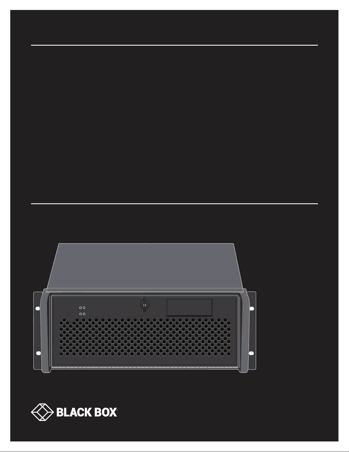
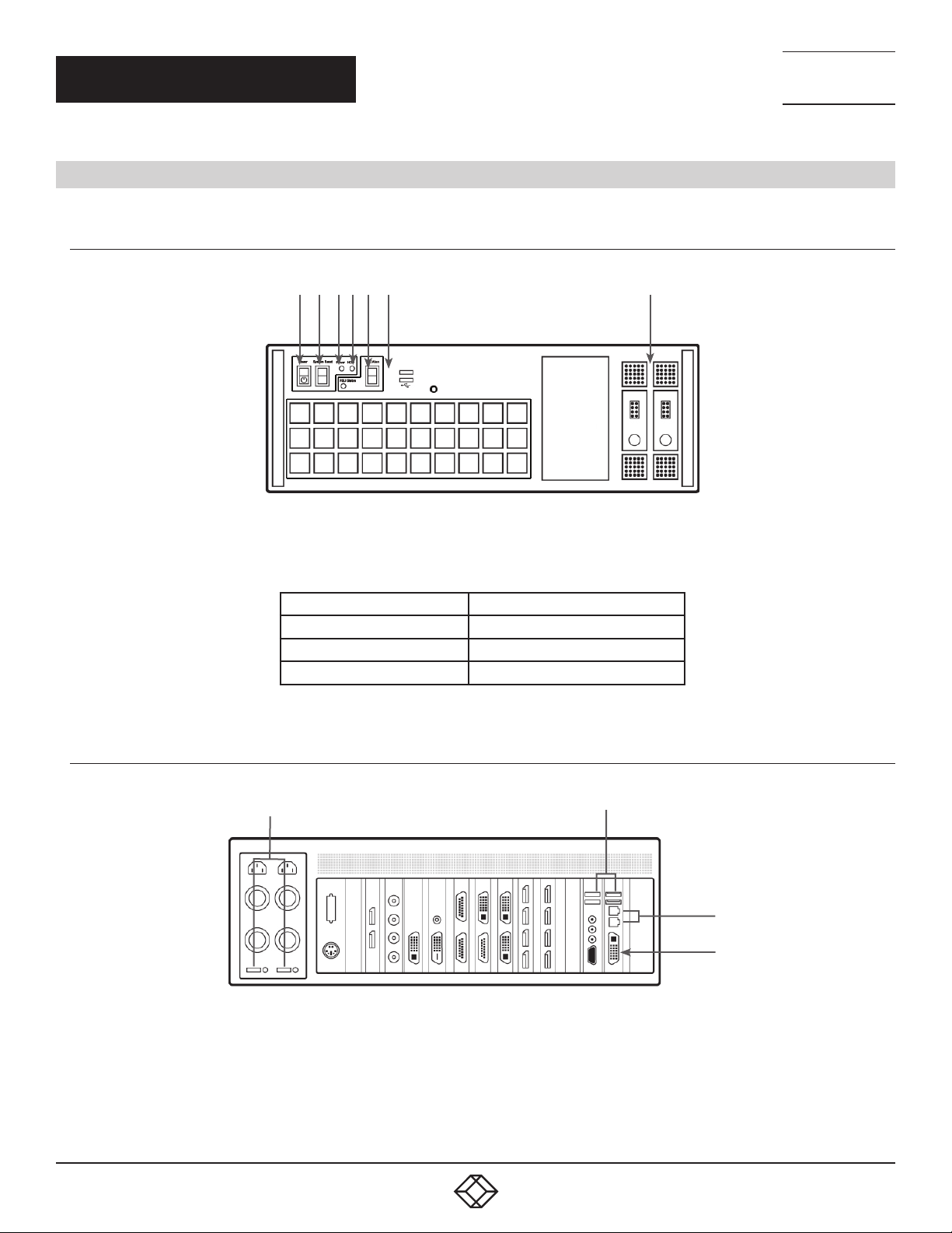
STEP 1: KEYBOARD AND MOUSE
Connect Keyboard and Mouse to convenient USB Ports.
USB Ports are located on both the front and rear panels of the system. If the intention is to mount the Radian Flex wall controller in
a rack, it may be more convenient to use the USB ports on the front for easy access.
(4) external USB 2.0 ports (2 front panel, 2 rear panel)
(2) external USB 3.0 ports (rear panel)
Rear Panel
TECHNICAL
SUPPORT
1. 8 7 7. 8 7 7. 2 2 69
Front Panel
FIGURE 1.
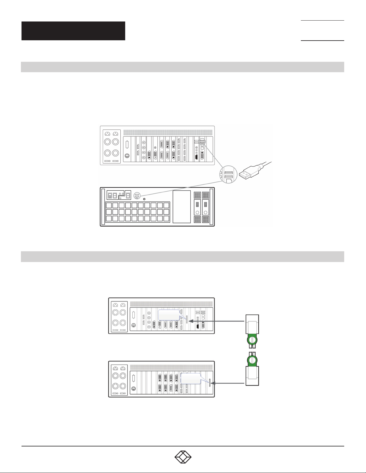
STEP 2: CONNECT EXPANSION CHASSIS (OPTIONAL)
A Radian Flex Expansion Chassis may have been purchased as part of a large video wall system or ordered separately. Connect
the Host Link card in the main system to the Slave Link card in the expansion chassis using the Extension Cable G3. The Extension
Cable G3 is packaged and shipped with the Radian Flex Expansion Chassis.
Host Link
Slave Link
FIGURE 2.
For connecting Optical Expansion products, consult the User Guide located later in this document.
1. 8 77. 8 77. 226 9 BLACKBOX.COM
5
NEED HELP?
LEAV E TH E TEC H TO US
LIVE 24/7
QUICK START GUIDE
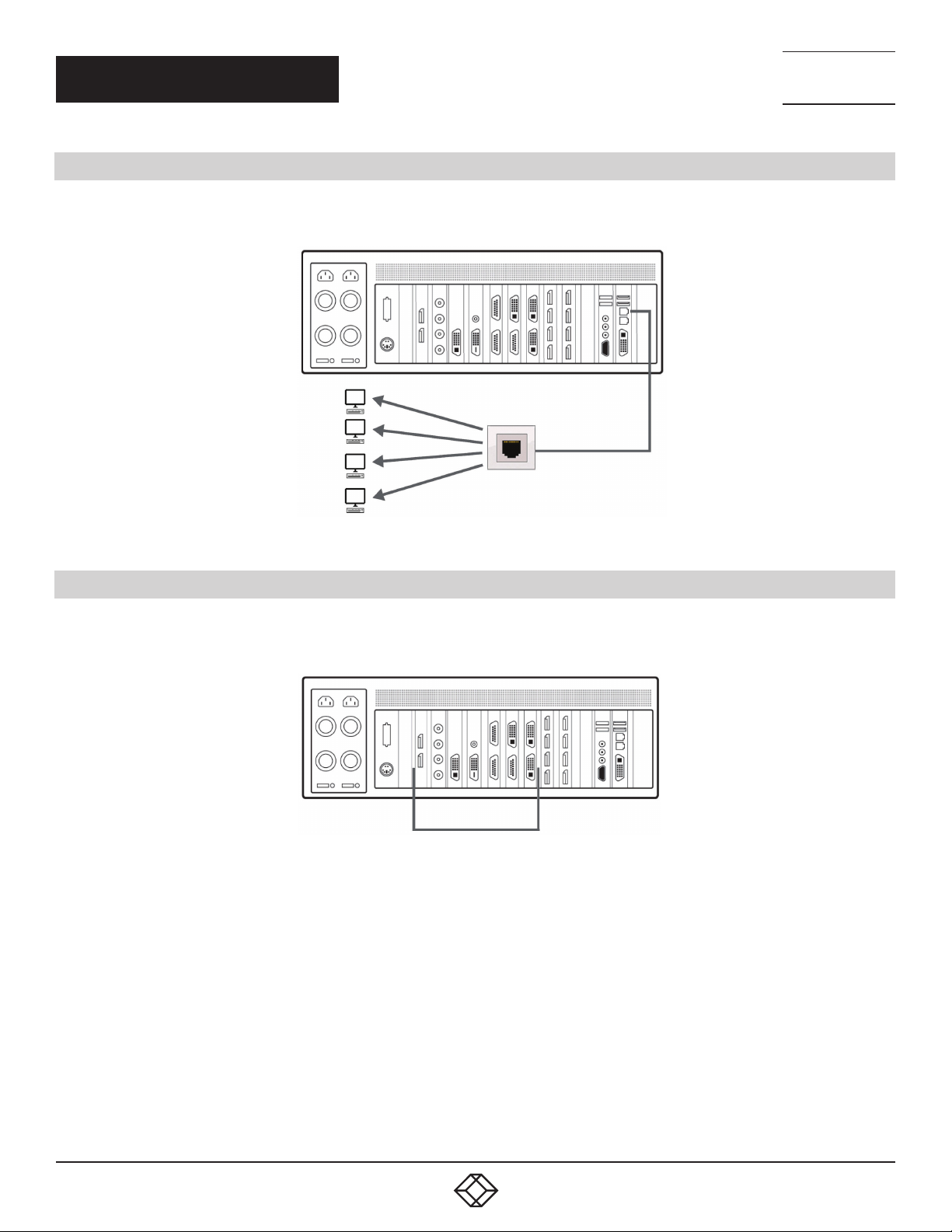
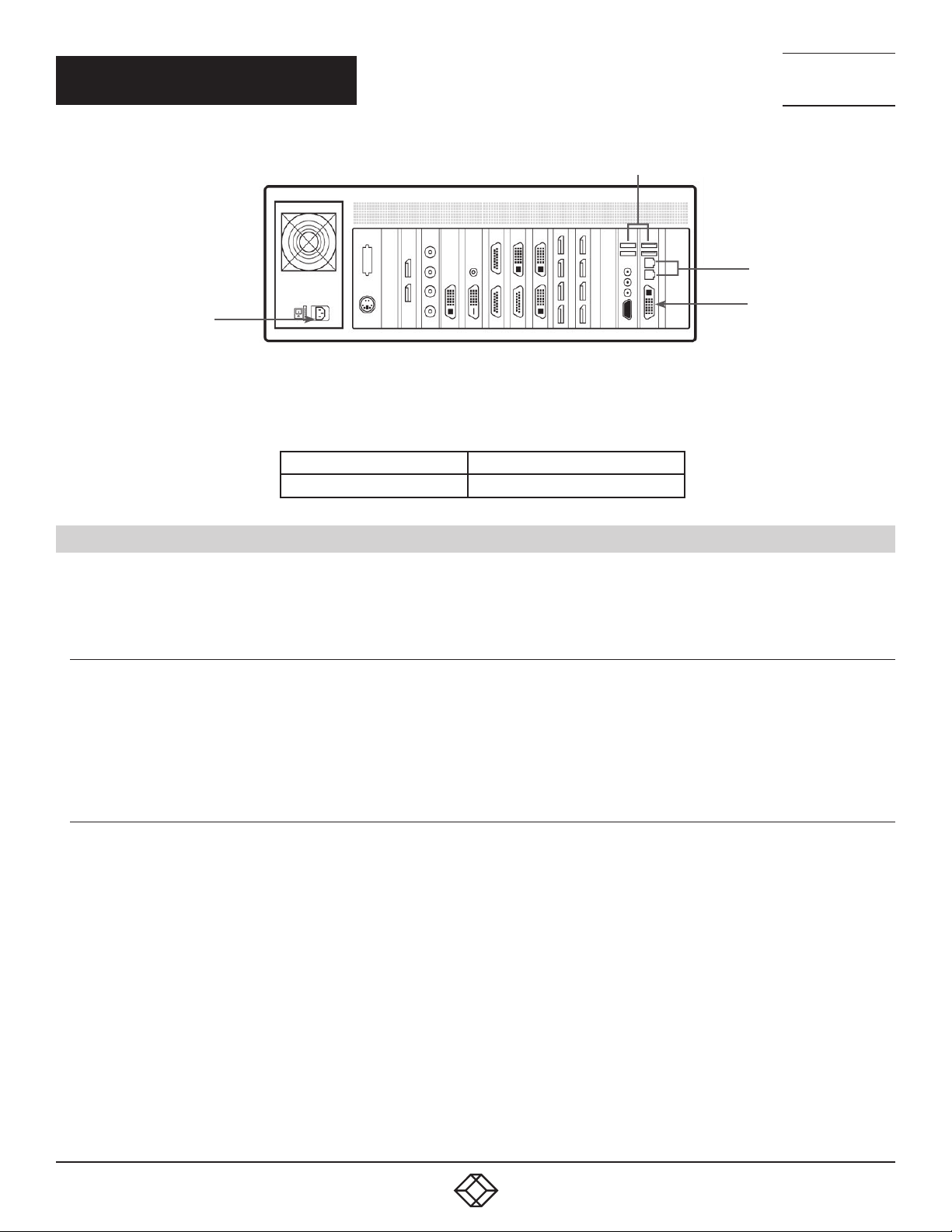
STEP 3: CONNECT TO A NETWORK (OPTIONAL)
If the wall controller is to be used over a network, connect the controller to a network point (cables not supplied) using one of the
LAN connectors on the rear panel.
TECHNICAL
SUPPORT
1. 8 7 7. 8 7 7. 2 2 69
FIGURE 3.
STEP 4: CONNECT INPUT SOURCE
As each wall controller is custom built, the number and type of video inputs will differ from system to system. If you have
purchased a wall controller with video inputs, the input connectors are located on the rear panel as shown in the example below:
Video Input Connectors
FIGURE 4.
Connect the input sources to the relevant video input connectors; cables may be supplied for some inputs, see content list for details.
6
1. 8 77. 8 77. 226 9 BLACKBOX.COM
NEED HELP?
LEAV E TH E TEC H TO US
LIVE 24/7
QUICK START GUIDE
TECHNICAL
SUPPORT
1. 8 7 7. 8 7 7. 2 2 69
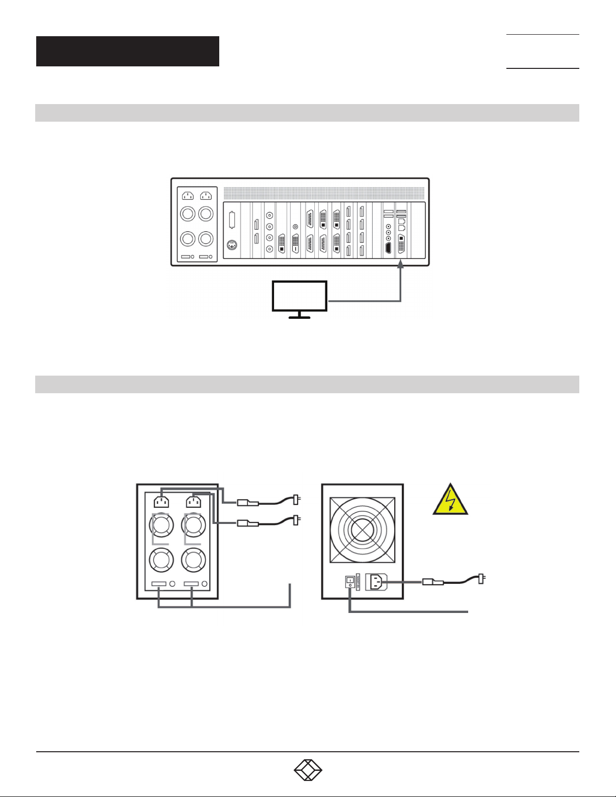
STEP 5: CONNECTING A CONTROL SCREEN
Your wall controller is configured to use a control screen connected to the systems’ internal graphics device before leaving the factory.
Connect the control screen to the motherboard graphics output connector on the rear of the wall controller. A control screen is initially
required to set up the system including the operating system (Windows 10).
VGA or DVI
Control Screen
FIGURE 5.
STEP 6: POWERING THE SYSTEM
Radian Flex wall controllers are supplied with either a Redundant Power Supply Unit (RPSU) or an ATX power supply. An RPSU power
supply requires two power cables and an ATX supply requires one power cable. All power cables are supplied with your wall controller.
1. Connect power cable(s) to the wall controller then plug into a main power supply.
2. Switch on the power supply units.
1
1
2
RPSU Power Switch
2
ATX Power Switch
FIGURE 6.
1. 8 77. 8 77. 226 9 BLACKBOX.COM
7
NEED HELP?
LEAV E TH E TEC H TO US
LIVE 24/7
QUICK START GUIDE
3. Switch on the system using the power button on the front panel.
3
FIGURE 7.
NOTE: If you have a Radian Flex Expansion Chassis connected to the main unit (Step 2), the power supply units on the expansion
chassis should be switched on prior to the main wall controller. There is no requirement to switch on the expansion chassis on the
front panel (3).
TECHNICAL
SUPPORT
1. 8 7 7. 8 7 7. 2 2 69
STEP 7: WINDOWS 10 SETUP
Once the system has been built and congured in our factory, the operating system is resealed, and when you switch the system on
for the rst time, the operating system setup begins. You will be prompted to enter information to set up the Windows 10 operating
system.
There is no requirement for users to activate Windows 10, activation is done automatically. An internet connection is required for the
automatic activation.
STEP 8: DISPLAY CONFIGURATION
Once the Windows 10 setup is complete, the wall controller will reboot and the control screen will show a Windows desktop
displaying the Display Driver Conguration Tool (DDCT). The DDCT will guide you, step-by-step, through the conguration of the
graphics outputs, enabling you to quickly create one or more video walls.
On the nal stage of the conguration, the DDCT will recommend the optimum way to connect your wall controller to your video wall
displays.
A full description of the DDCT can be found in the User Guide located later in this document.
It is recommended that you carefully read the instructions on each page of the wizard. To begin your wall conguration, click on “Start
Wizard.”
FIGURE 8.
8
1. 8 77. 8 77. 226 9 BLACKBOX.COM

QUICK START GUIDE
Select the type of displays being used on your wall:
Displays With Bezels – Monitors, TVs and DLP Cubes
Overlappable Displays – Projectors
LED Displays
NEED HELP?
LEAV E TH E TEC H TO US
LIVE 24/7
TECHNICAL
SUPPORT
1. 8 7 7. 8 7 7. 2 2 69
FIGURE 9.
Click on “Continue.”
The tool will then display a conguration page for the type of display you selected.
FIGURE 10.
1. 8 77. 8 77. 226 9 BLACKBOX.COM
9

NEED HELP?
LEAV E TH E TEC H TO US
LIVE 24/7
QUICK START GUIDE
What Types of Displays do you Have?
Use the “Manufacturer” and “Model” drop-down lists to select the displays you are using for your wall. If the wall consists of different
displays, select each one in turn to congure the type of display. The DDCT has an extensive database of displays; however, if your
display is not contained in the list, you can input the details manually by selecting “Create Custom Display.”
We strongly recommend that you take measurements from the display manufacturer’s specications if available.
TECHNICAL
SUPPORT
1. 8 7 7. 8 7 7. 2 2 69
FIGURE 11.
Add Displays
Add Displays is available for displays with bezels or overlappable displays. Use the “Displays Across” and the “Displays Up” to create
your Display Group. Once created, congure the displays using “What Type of Displays Do You Have?” When using overlappable
displays, “Display Overlap” becomes available, enabling you to select a percentage of overlap between displays.
FIGURE 12.
10
1. 8 77. 8 77. 226 9 BLACKBOX.COM
QUICK START GUIDE
NEED HELP?
LEAV E TH E TEC H TO US
LIVE 24/7
TECHNICAL
SUPPORT
1. 8 7 7. 8 7 7. 2 2 69
FIGURE 13.
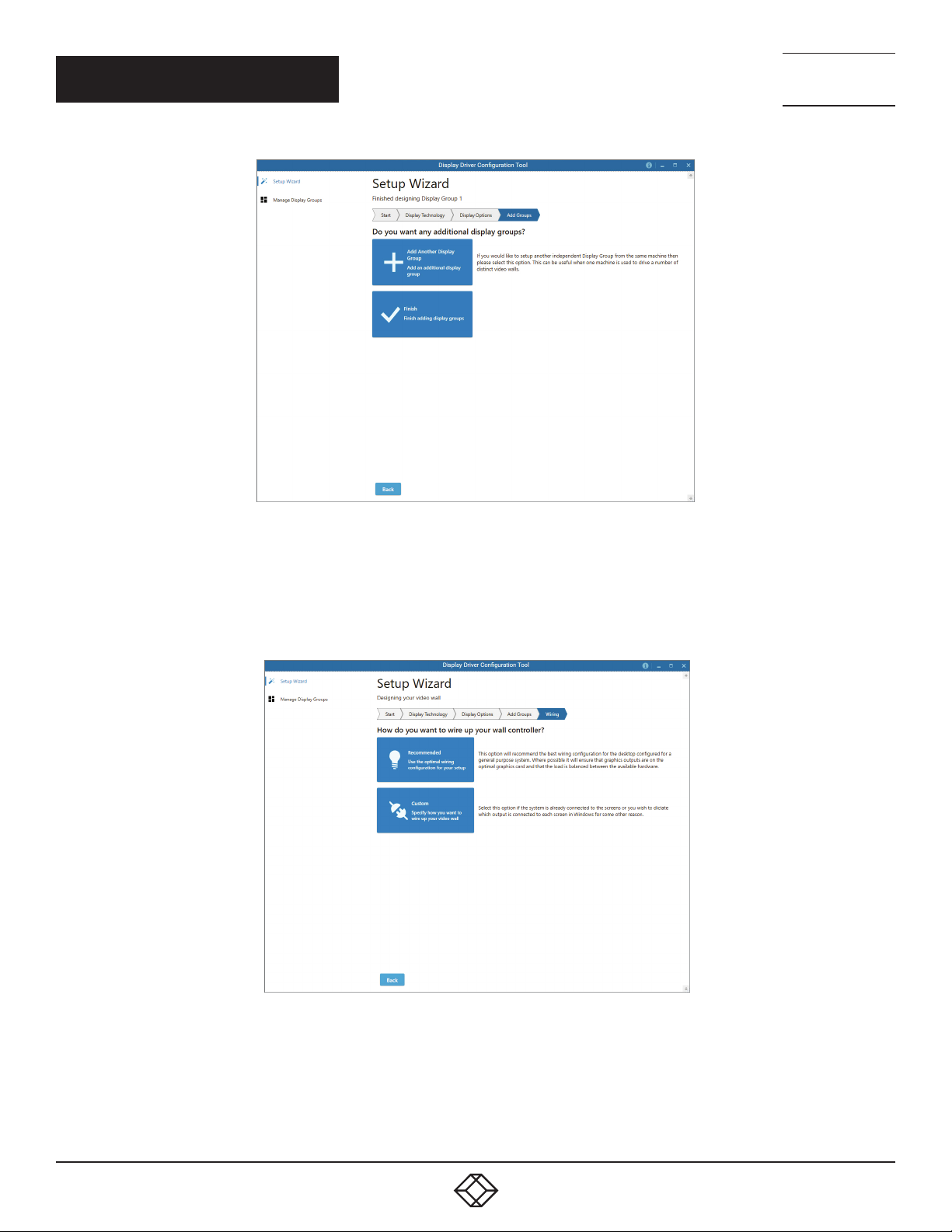
At this stage of the setup, you can choose to create another independent display group from the same system; this would be
considered if one machine will be used to drive a number of separate video walls. See the User Guide section for more details.
If another display group is not required, click on “Finish” and the following page is displayed:
FIGURE 14.
The DDCT can recommend the best wiring conguration for the displays and your system, ensuring the load is balanced
between the graphics hardware. Click on “Recommended” for the optimal conguration for your system.
(If you want to manually wire your system and decide for yourself which output is connected to which display, click on “Custom.”)
1. 8 77. 8 77. 226 9 BLACKBOX.COM
11
QUICK START GUIDE
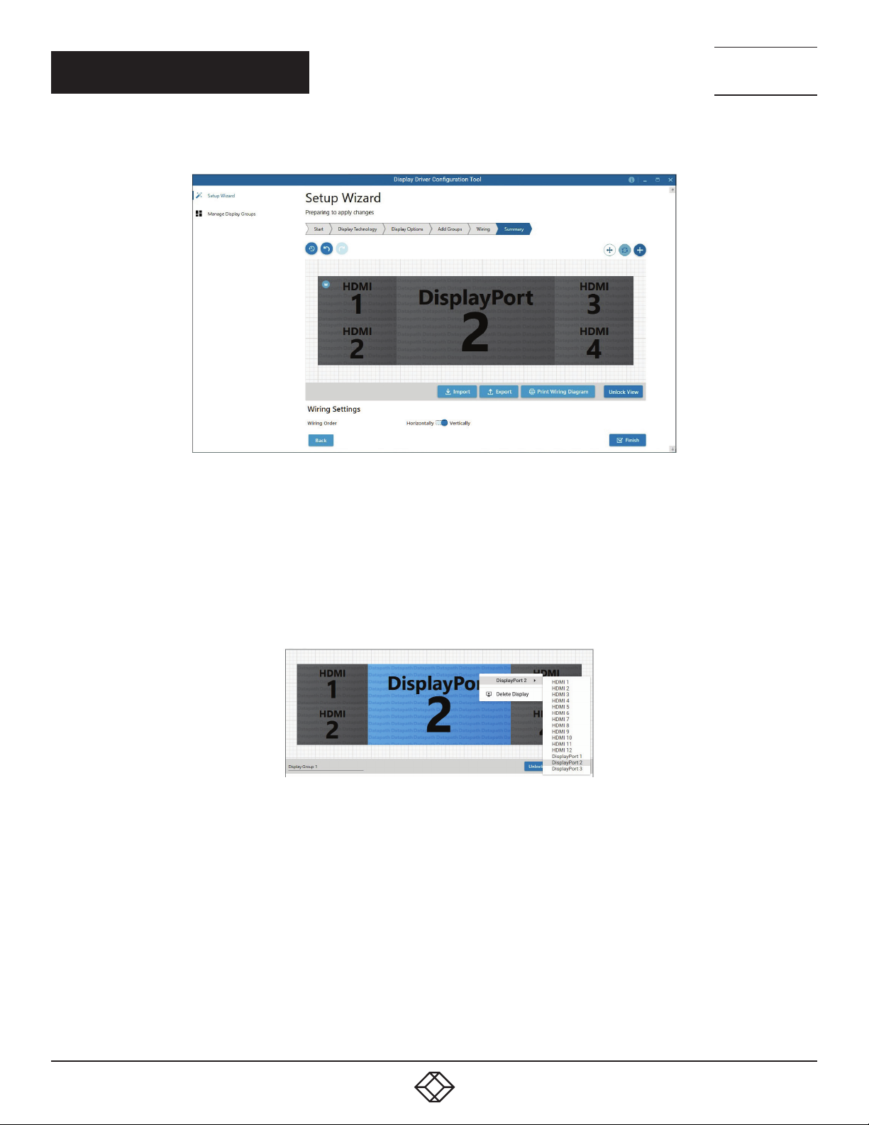
You will be next be presented with the Summary page:
NEED HELP?
LEAV E TH E TEC H TO US
LIVE 24/7
TECHNICAL
SUPPORT
1. 8 7 7. 8 7 7. 2 2 69
FIGURE 15.
If you chose to have the DDCT congure your wiring, this page will display the recommended display connections, as shown above.
Connect each display to the corresponding output connector on the rear of the wall controller.
NOTE: For help, contact Black Box Technical Support at 877-877-2269 or info@blackbox.com for details.
To manually select the outputs, right-click on the display group and select “Edit.” You can then select each individual display and
allocate your preferred output. Right-click on a selected display to reveal the list of outputs available:
+
FIGURE 16.
When all outputs have been allocated by either “Recommended” or “Custom,” click on “Finish.” You will then be prompted to save the
changes to your video wall and restart your system. When restarted, the Windows Desktop will be displayed across the wall.
You can access the conguration tool at anytime if you want to make changes. Right-click on the desktop and select Display Driver
Conguration Tool from the menu.
12
1. 8 77. 8 77. 226 9 BLACKBOX.COM
NEED HELP?
LEAV E TH E TEC H TO US
LIVE 24/7
QUICK START GUIDE
TECHNICAL
SUPPORT
1. 8 7 7. 8 7 7. 2 2 69
STEP 9: RADIAN STANDARD VIDEO WALL SOFTWARE
Before opening the Radian Standard Video Wall Software Client interface, you may need to start the Radian Standard Video Wall
Software Server if it does not start automatically. The Server icon is displayed in the System Tray.
Server icon —>
If the Server fails to start automatically, start the Server by clicking on it in the “All Programs” menu. The Radian Standard Video Wall
Software Client will only detect servers that are running.
Start | All Programs | Radian Standard Video Wall Software - Server
Open the Radian Standard Video Wall Software Client
Start | All Programs | Radian Standard Video Wall Software - Client
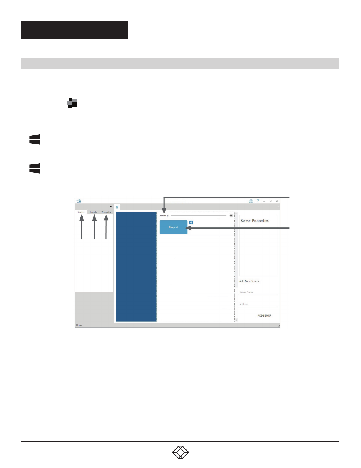
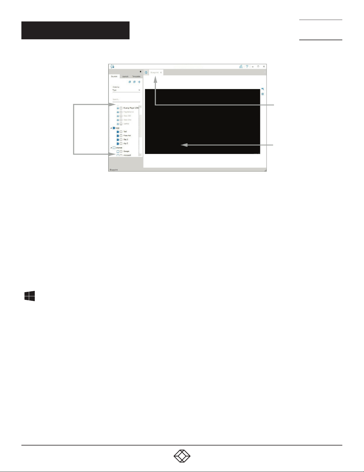
The Radian Standard Video Wall Software - Client
3 4 5
FIGURE 17.
1. Indicates the server you are connected to.
2. A representation of the display wall associated with the server.
1
2
3. Sources Tab - Displaying all the sources connected to the server for use on your display wall.
4. Layouts Tab - Use to save, recall and share display wall layout congurations.
5. Templates Tab - Use templates to assist in the design of specic display wall layouts.
Click on the display wall representation (2) as shown on the previous illustration to open the display wall tab.
1. 8 77. 8 77. 226 9 BLACKBOX.COM
13
QUICK START GUIDE
Sources
FIGURE 18.
NEED HELP?
LEAV E TH E TEC H TO US
LIVE 24/7
TECHNICAL
SUPPORT
1. 8 7 7. 8 7 7. 2 2 69
Display Wall
Tab
Display Wall
Representation
When opened, the display wall tab shows a live representation of the physical wall and the sources available to display on it. To place a
source on the video wall, simply click on the required source in the sources tab and drag it onto the display wall representation.
(NOTE: It is not possible to drag Application sources, double-click to open.)
The application help file contains information explaining how multiple sources can be selected, how to use and create templates and how
to save, recall and share layout files.
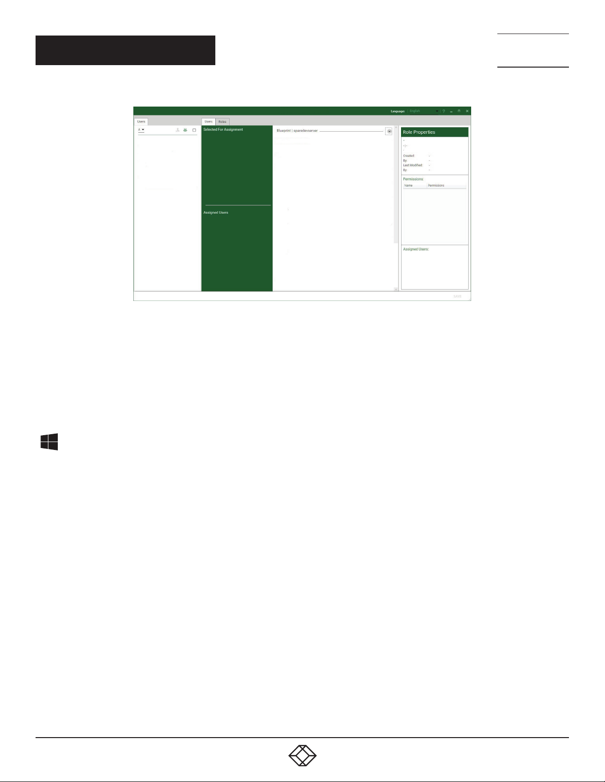
The Radian Video Wall Software - Security Administration Client (Only Available with Radian Video Wall Software)
A Radian Video Wall Software serial dongle must be inserted into a vacant USB port. If the dongle is removed or swapped, the
Security Client will not open and an error message is displayed, so do not remove the dongle.
If you have purchased Radian Video Wall Software, the license dongle is located in the accessories box.
Start | All Programs | Radian Video Wall Software - Security Administration Client
14
1. 8 77. 8 77. 226 9 BLACKBOX.COM
QUICK START GUIDE
NEED HELP?
LEAV E TH E TEC H TO US
LIVE 24/7
TECHNICAL
SUPPORT
1. 8 7 7. 8 7 7. 2 2 69
FIGURE 19.
The Radian Video Wall Software - Security Administration Client allows Administrators to assign specic users to roles on a wall-by-wall
basis. For example, a user can be assigned a role allowing unrestricted access on one wall but assigned a role on another wall that only
allows the opening of pre-determined layouts.
Before using Security Client for the rst time, the SecurityOnOff.exe program must be running to enable security protection for the
application. To manually run the SecurityOnOff.exe, make sure you are logged into Windows with Administrator Rights.
Locate and double click on the SecurityOnOff.exe le:
Program Files|Radian Video Wall Software| Security Server|SecurityOnOff
The Radian Video Wall Software Security Application help le contains information on how to:
Import users from the Windows Active Directory into the database
Create and edit roles
Assign permissions to providers, layouts and sources, giving specific roles access to them
Assign roles to walls
1. 8 77. 8 77. 226 9 BLACKBOX.COM
15

QUICK START GUIDE
STEP 10: VIDEO WALL MANAGER (OPTIONAL)
Start | All Programs | Video Wall Manager | Video-Wall-Manager-My Computer
NEED HELP?
LEAV E TH E TEC H TO US
LIVE 24/7
TECHNICAL
SUPPORT
1. 8 7 7. 8 7 7. 2 2 69
1
1. The Icons displayed in the application toolbar identify the type of source available to each input.
2. Icons highlighted green indicate an active capture for that particular input.
3. Representation of the control screen if one is being used.
4. Representation of the video wall desktop.
2 3
FIGURE 20.
4
FIGURE 21.
To open a video window, click and drag an active capture into the Radian Video Wall Software application.
Use the Help Menu for a comprehensive guide on the features of the Radian Video Wall Software application.
16
1. 8 77. 8 77. 226 9 BLACKBOX.COM
NEED HELP?
LEAV E TH E TEC H TO US
LIVE 24/7
CHAPTER 1: OVERVIEW
1.1 INTRODUCTION
The Radian Flex Video Wall Controller system has been manufactured and tested to the highest standards offering unparalleled
quality and reliability. The aim of this user guide is to assist you through the installation of the system safely and effectively and act
as a reference guide for future use. Do not switch on the system until all the relevant cables have been connected.
1.2 SYS TEM S
The systems covered by this user guide are the Radian Flex 4-, 9-, and 11-slot video wall controllers and expansion chassis ranges.
1.3 HOW THE USER GUIDE IS ORGANIZED
The user guide is broken down into chapters and each chapter into sections. Chapters, sections and pages are numbered
individually.
1.4 SYMBOLS
Symbols are used throughout this user guide to assist the user in quickly identifying important safety information and notes.
TECHNICAL
SUPPORT
1. 8 7 7. 8 7 7. 2 2 69
Yellow triangle indicates that failure to observe the instructions could result in injury and/or damage to the system.
Lifting precautions should be considered.
White arrow in a black box indicates a useful tip.
White exclamation mark in a black box indicates important information.
1.5 TERMINOLOGY AND DEFINITIONS
BIOS: Basic Input/Output System: Used during system boot up to initialize and test system hardware and load the operating system.
Each BIOS is specically designed to work with a particular motherboard.
Command Line Interface: Preferred means by advanced users of issuing commands and controlling an application or operating
system. Programs with a Command Line Interface are generally considered easier to automate via scripting.
Control Screen: All systems are shipped with the BIOS congured to boot the system off the onboard graphics device. This output
can then be used as the Control Screen for a typical video wall. The content of the control screen is not displayed on the video wall
desktop and can be used to host the Video Wall Manager application window.
SBC: A Single Board Computer built on a single circuit board. SBCs in the systems are plugged into the PICMG1.3 slot on the 9- and
11-slot backplanes.
SDK: Software Development Kit: A set of software development tools which allows the creation of certain applications.
Radian Standard Video Wall Software (Optional): An optional software application for controlling and managing Video Capture Cards,
IP Camera and third party application windows on a Radian Flex Video Wall Controller. It provides a graphical representation of the
video wall and a toolbar to manipulate all available input sources and applications.
1. 8 77. 8 77. 226 9 BLACKBOX.COM
17

NEED HELP?
LEAV E TH E TEC H TO US
LIVE 24/7
CHAPTER 1: OVERVIEW
Radian Video Wall Software Security Administration Client (Optional): The Radian Video Wall Software Security Administration Client
allows Administrators to assign specic users to roles on a wall by wall basis. The Security Administration Client is only available with
Radian Video Wall Software.
Video Wall Controller Software: A software application that enables the user to monitor the temperatures and voltages of system components.
Screen Order: The order in which the screens appear on the display wall.
TECHNICAL
SUPPORT
1. 8 7 7. 8 7 7. 2 2 69
18
1. 8 77. 8 77. 226 9 BLACKBOX.COM

NEED HELP?
LEAV E TH E TEC H TO US
LIVE 24/7
CHAPTER 2: SAFETY
TECHNICAL
SUPPORT
1. 8 7 7. 8 7 7. 2 2 69
2.1 SAFETY PRECAUTIONS
To prevent damage to your Black Box product or injury to personnel operating the equipment, please read the following safety
precautions before operation. These instructions should be made available to all those who will use and operate Black Box products.
2.1.1 P OW E R S U P PLY
These products require a main power supply. This power supply must be disconnected when equipment is being upgraded
or relocated.
2.1.2 C A B LE S
Do not expose cables to any liquids; doing so may cause a short circuit which could damage the equipment. Do not place heavy
objects on top of any cables because this can cause damage and possibly lead to exposed live wires.
2.1.3 VENTILATION
All computer equipment should be located in a well ventilated area. All ventilation holes on the computer casing must be kept clear
of any obstruction at all times. Failure to do so will result in the system overheating and damaging your equipment.
2.1.4 WORKING ENVIRONMENT
Locate the equipment in an environment free from dust, moisture and extreme changes in temperature. Place the equipment on a
stable and solid work surface. Do not place liquids (hot/cold drinks, etc.) near the equipment as spillage could cause serious damage.
2.1.5 GAS/FLAMMABLE LIQUIDS
Never use electronic equipment in the presence of gas or any ammable liquid, doing so could result in an explosion or serious re.
2.1.6 SMOKE/UNUSUAL SMELLS
If you notice smoke or unusual smells being emitted from your system, turn off and unplug the system from the power supply.
The system should then be passed to a qualied technician for inspection. Continued operation could result in personal injury
and damage to property.
2.1.7 MAINTENA NCE
Apart from what is detailed in this user guide, maintenance should only be carried out by competent technicians, any Black Box
plug-in cards that are physically damaged should be returned to Black Box for repair using Black Box RMA procedures.
1. 8 77. 8 77. 226 9 BLACKBOX.COM
19
NEED HELP?
LEAV E TH E TEC H TO US
LIVE 24/7
CHAPTER 2: SAFETY
2.1.8 REPACEABLE BATTERIES
CAUTION: Risk of explosion if batteries are replaced with an incorrect type. Dispose of used batteries according to the local laws/
regulations and manufacturer’s instructions.
2.2 RACKMOUNT SAFETY INSTRUCTIONS
2.2.1 TEM PE R ATUR E
If Radian Flex Chassis systems are to be installed in a closed or multi-unit rack assembly, the installation should be such that the
amount of air ow required for safe operation of the equipment is not compromised. The operating ambient temperature of the rack
environment should be maintained below 95° F (35° C) under all conditions. Appropriate cooling arrangements should be built into the
cabinet to ensure that this specication is maintained.
TECHNICAL
SUPPORT
1. 8 7 7. 8 7 7. 2 2 69
2.2.2 MECHANICAL LOADING
Mounting of the equipment in the rack should be such that a hazardous condition is not achieved due to uneven mechanical loading.
2.2.3 CIRCUIT OVERLOADING
Consideration should be given to the connection of the equipment to the main supply circuit and the effect that overloading of the
supply might have on any over-current protection or supply wiring. Appropriate consideration of equipment nameplate ratings should
be used.
2.2.4 RELIABLE EARTHING
Reliable earthing of all rack-mounted equipment should be maintained. Particular attention should be given to supply
connections other than direct connections to the branch circuit (e.g. use of power strips).
2.3 UNPACKING AND INITIAL INSPECTION
2.3.1 UNPACKING
The system is heavy; lifting precautions should be considered.
To unpack the system, follow the instructions provided on the outside of the packaging. All packaging materials should be retained
for future transit.
2.3.2 INITIAL INSPECTION
All systems are carefully prepared for shipment and every effort is made to ensure you receive the product in pristine condition.
On receipt, you should carefully inspect the outer packaging for any transit damage, i.e. any signs that the system may have been
dropped, etc.
20
1. 8 77. 8 77. 226 9 BLACKBOX.COM

NEED HELP?
LEAV E TH E TEC H TO US
LIVE 24/7
CHAPTER 2: SAFETY
TECHNICAL
SUPPORT
1. 8 7 7. 8 7 7. 2 2 69
Use the packing list enclosed to establish that all the items are present. If any items from the packing list are missing, contact Black
Box Technical Support at 877-877-2269 or info@blackbox.com.
Check the chassis for damage that could have an adverse affect on the operation of the system or could cause injury to the
operator. If there is any physical damage to the power supply unit, for example, damaged power sockets or exposed
wiring, do not connect to a power source, contact Black Box Technical Support at 877-877-2269 or info@blackbox.com.
1. 8 77. 8 77. 226 9 BLACKBOX.COM
21
NEED HELP?
LEAV E TH E TEC H TO US
LIVE 24/7
CHAPTER 3: GENERAL
3.1 O VE R VI E W
Black Box Radian Flex systems are powerful video wall controllers, capable of delivering Ultra High Denition video across large,
multi-screen display installations. Use it in a host of environments, from CCTV security suites to sports stadiums, and from military
installations to utility management centers. The Chassis are fully compatible with Radian Flex PCI Express video capture and graphics
cards that offer Ultra High Denition video for storage and display, including the ability to capture HDCP sources without any display
restrictions. Each system has been designed for use in demanding control room environments. Each component has been subjected
to rigorous testing to ensure the highest levels of performance and reliability.
Features include:
High performance and reliability in demanding conditions
Suited for 24/7 applications
Can be operated via a network
PCIe switched fabrics enables systems to be expanded using additional expansion chassis
Video Wall Software (optional) - Display video on the desktop in real time using an array of features
Video Wall Controller Software software (optional) - Provides monitoring of the temperature and voltage sensors on system
components
TECHNICAL
SUPPORT
1. 8 7 7. 8 7 7. 2 2 69
3.2 RADIAN FLEX CHASSIS
TABLE 3-1. CHASSIS MODELS AND FEATURES
Systems Features
4-Slot
Backplane
VWP-FLEX-961 x x x x x
VWP-FLEX-1182 x x x
VWP-FLEX-962X x x x x
VWP-FLEX-1182X x x x x
VWP-FLEX-1182DX x x x x
VWX-2090* x x x
VWX-2110 x x
VWP-FLEX-951 x x x
VWP-FLEX-962 x x x
9-Slot
Backplane
11-Slot
Backplane
SBC 5 SBC 6 SBC 7
Intel®
Core i5
Intel
Core i7
Dual E5®
Core Xeon
Single E3
Intel Core
Xeon
RPSU ATX
* Available with either an RPSU or ATX power supply.
22
1. 8 77. 8 77. 226 9 BLACKBOX.COM
CHAPTER 3: GENERAL
3.3 ASSOCIATED INPUT/OUTPUT CARDS AND RELATED PRODUCTS
TABLE 3-2. INPUT/OUTPUT CARDS AND RELATED PRODUCTS
Product Description
VGC-DP-4 and
VGC-DP-4-R2
VCC-STREAM Dedicated IP Streaming decoding card
VCC-HDMI2-2 Two independent HDMI 2.0 capture channels with HDCP 2.2 support
VCC-DP-2 Dual channel, 4K UHD DisplayPort capture card
VCC-SDI-4 Four channel 3G-SDI video capture card
VCC-HD-4-H Quad HDMI video capture card
VCC-SD-HD-A-2,
VCC-SD-HD-3,
VCC-SDI-SD-HD-3-HD
VCC-SD-HD-A-2,
VCC-SD-HD-3,
VCC-SDI-SD-HD-3-SDI
VCC-HD-4 Eight lane PCI Express capture card with four independent DVI-I HD channels
VCC-SD-HD-A-2,
VCC-SD-HD-3,
VCC-SDI-SD-HD-3
Host Link Host link card for expansion systems
Slave Link Slave link card for expansion systems
Extension Cable Copper cable for expansion systems
Quad output DisplayPort graphics card
Four lane PCI Express capture card with 2 x HD DVI-I and 1 SD channels
Four lane PCI Express capture card with 1 x HD DVI-I, SD, SDI channels
Single Channel HD and single channel SD video capture card
NEED HELP?
LEAV E TH E TEC H TO US
LIVE 24/7
TECHNICAL
SUPPORT
1. 8 7 7. 8 7 7. 2 2 69
1. 8 77. 8 77. 226 9 BLACKBOX.COM
23
CHAPTER 4: HARDWARE
4.1 C H AS S IS
4.1.1 FRONT
NEED HELP?
LEAV E TH E TEC H TO US
LIVE 24/7
TECHNICAL
SUPPORT
1. 8 7 7. 8 7 7. 2 2 69
3
1
2
TABLE 4-1. COMPONENTS OF THE CHASSIS FRONT
1 = Power, on-off 5= Reset Button
2= PSU Alarm Reset 6= USB Ports
3= Power LED 7= Removable Hard Drives
4= HDD LED
6
4 5
FIGURE 4-1. FRONT OF THE CHASSIS
7
4.1.2 R E A R
24
R1
R2
R3
R4
FIGURE 4-2. REAR PANEL - RPSU
1. 8 77. 8 77. 226 9 BLACKBOX.COM
CHAPTER 4: HARDWARE
R2
NEED HELP?
LEAV E TH E TEC H TO US
LIVE 24/7
TECHNICAL
SUPPORT
1. 8 7 7. 8 7 7. 2 2 69
R3
R1
FIGURE 4-3. REAR PANEL - ATX (VWP-FLEX-961 ONLY)
TABLE 4-2. COMPONENTS OF THE CHASSIS REAR
R1= Power Switch R3= Ethernet Ports
R2= USB Ports R4= DVI-I Output
4.2 SINGLE BOARD COMPUTERS (SBCS)
SBCs are for use in the range of video wall controllers providing improvements to the BIOS and a higher performance for Windows
based software applications.
4.2.1 SBC5
The Advantech PCE-9228G2:
An Intel
Used in the VWP-FLEX-1182DX
®
Dual Xeon® E5-2600v3
R4
4.2.2 SBC6
The Portwell 8113-Q170:
An Intel® 7th Gen Kaby Lake Pentium Core i7
Used in the VWP-FLEX-962 and the VWP-FLEX-1182
1. 8 77. 8 77. 226 9 BLACKBOX.COM
25

NEED HELP?
LEAV E TH E TEC H TO US
LIVE 24/7
CHAPTER 4: HARDWARE
4.2.3 SBC7
The Portwell 8113-C236:
A Single E3 Xeon processor
Used in the VWP-FLEX-962X and the VWP-FLEX-1182X
4.3 BACKPLANES
The Radian Flex backplanes use advanced PCI Express switches to create a high bandwidth fabric for connecting multiple PCI
Express into a system.
4.3.1 4-SLOT BACKPLANE
4-Slot Backplane
Used in the VWP-FLEX-951
TECHNICAL
SUPPORT
1. 8 7 7. 8 7 7. 2 2 69
4.3.2 9-SLOT BACKPLANE
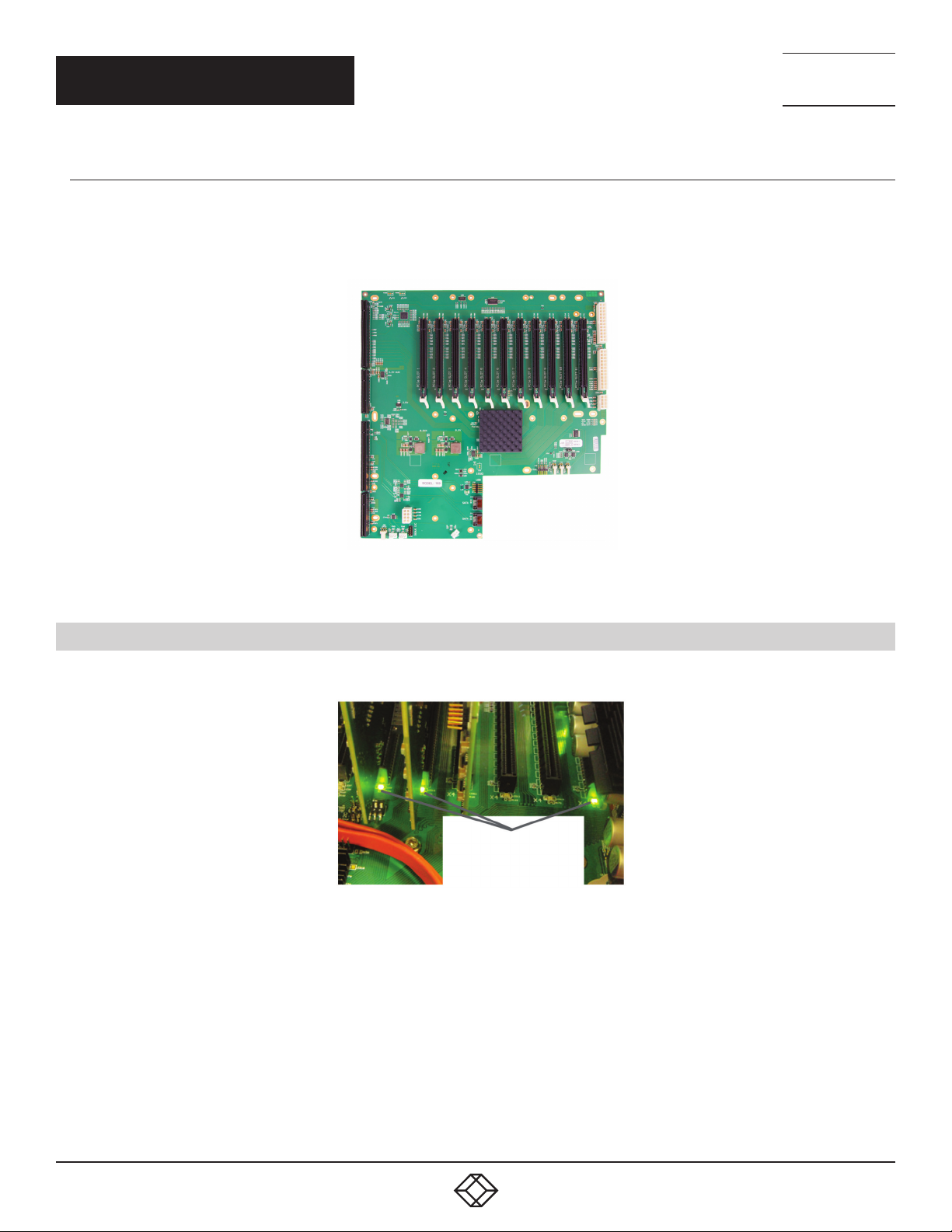
Nine slot PCI Express backplane - 8 x 4 lane slots, 1 x 8 lane slot and 1 x PICMG 1.3 slot
Used in the VWP-FLEX-961, VWP-FLEX-962X, and the VWX-2090
FIGURE 4-4. 9-SLOT BACKPLANE
26
1. 8 77. 8 77. 226 9 BLACKBOX.COM
CHAPTER 4: HARDWARE
4.3.3 11-SLOT BACKPLANE
Eleven slot PCI Express backplane - 11 x 8 lane PCI Express slot and one PICMG 1.3 slot
Used in the VWP-FLEX-1182, VWP-FLEX-1182X, VWP-FLEX-1182DX and the VWX-2110
NEED HELP?
LEAV E TH E TEC H TO US
LIVE 24/7
TECHNICAL
SUPPORT
1. 8 7 7. 8 7 7. 2 2 69
FIGURE 4-5. 11-SLOT BACKPLANE
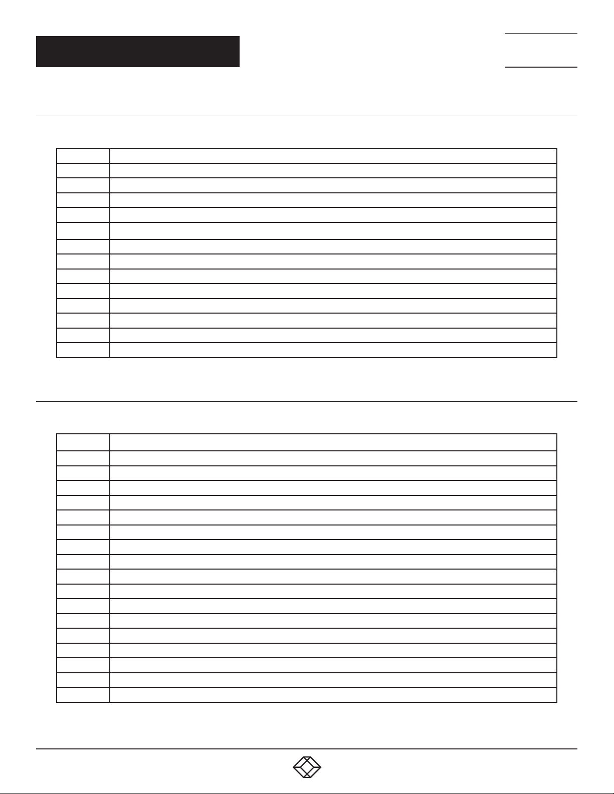
4.4 BACKPLANE LEDS
The 4-slot, 9-slot, and 11-slot backplanes have LEDs tted for each PCI Express slot and the PICMG1.3 slot.
LEDs
FIGURE 4-6. LEDS
1. 8 77. 8 77. 226 9 BLACKBOX.COM
27
CHAPTER 4: HARDWARE
4.4.1 9-SLOT BACKPLANE LEDS
TABLE 4-3. 9-SLOT BACKPLANE LEDS
LED1 ON = +5V STANDBY VOLTAGE PRESENT
LED2 ON = +5V SUPPLY PRESENT
LED3 ON = +12V SUPPLY PRESENT
LED4 ON = +3.3V SUPPLY PRESENT
LED5 ON = PICMG LINK SPEED = GEN3, FLASH-FAST = GEN2, FLASH-SLOW = GEN1
LED7 ON = PCIE SLOT 1 LINK SPEED = GEN3, FL ASH-FAST = GEN2, FLASH-SLOW = GEN1
LED9 ON = PCIE SLOT 2 LINK SPEED = GEN3, FLASH-FAST = GEN2, FLASH-SLOW = GEN1
LED10 ON = PCIE SLOT 3 LINK SPEED = GEN3, FLASH-FAST = GEN2, FLASH-SLOW = GEN1
LE D 11 ON = PCIE SLOT 4 LINK SPEED = GEN3, FLASH-FAST = GEN2, FLASH-SLOW = GEN1
LED12 ON = PCIE SLOT 5 LINK SPEED = GEN3, FLASH-FAST = GEN2, FLASH-SLOW = GEN1
LED13 ON = PCIE SLOT 6 LINK SPEED = GEN3, FLASH-FAST = GEN2, FLASH-SLOW = GEN1
LED14 ON = PCIE SLOT 7 LINK SPEED = GEN3, FL ASH-FAST = GEN2, FLASH-SLOW = GEN1
LE D15 ON = PCIE SLOT 8 LINK SPEED = GEN3, FL ASH-FAST = GEN2, FL ASH-SLOW = GEN1
LED16 NOT USED
NEED HELP?
LEAV E TH E TEC H TO US
LIVE 24/7
TECHNICAL
SUPPORT
1. 8 7 7. 8 7 7. 2 2 69
4.4.2 11-SLOT BACKPLANE LEDS
TABLE 4-4. 11-SLOT BACKPLANE LEDS
D1 ON = +12V SUPPLY PRESENT
D2 ON = +3.3V SUPPLY PRESENT
D3 ON = +5V SUPPLY PRESENT
D4 ON = +5V STANDBY SUPPLY PRESENT
D5 ON = PICMG LINK SPEED = G3, FLASH -FAST = G2, FL ASH-SLOW = G1
D6 ON = PCIE SLOT 1 LINK SPEED = G3, FLASH-FAST = G2, FLASH-SLOW = G1
D7 ON = PCIE SLOT 2 LINK SPEED = G3, FLASH-FAST = G2, FLASH-SLOW = G1
D8 ON = PCIE SLOT 3 LINK SPEED = G3, FLASH-FAST = G2, FLASH-SLOW = G1
D9 ON = PCIE SLOT 4 LINK SPEED = G3, FLASH-FAST = G2, FLASH-SLOW = G1
D10 ON = PCIE SLOT 5 LINK SPEED = G3, FLASH-FAST = G2, FLASH-SLOW = G1
D11 ON = PCIE SLOT 6 LINK SPEED = G3, FLASH-FAST = G2, FLASH-SLOW = G1
D12 ON = PCIE SLOT 7 LINK SPEED = G3, FLASH-FAST = G2, FLASH-SLOW = G1
D13 ON = PCIE SLOT 8 LINK SPEED = G3, FLASH-FAST = G2, FLASH-SLOW = G1
D14 ON = PCIE SLOT 9 LINK SPEED = G3, FLASH-FAST = G2, FLASH-SLOW = G1
D15 ON = PCIE SLOT 10 LINK SPEED = G3, FLASH-FAST = G2, FLASH-SLOW = G1
D16 ON = PCIE SLOT 11 LINK SPEED = G3, FLASH-FAST = G2, FLASH-SLOW = G1
D17 ON= PLX FATAL ERROR
D24 ON = PSU FAULT
No LEDs flashing indicates that lane width has not been established. The LEDs will not flash on slots where no cards are installed.
28
1. 8 77. 8 77. 226 9 BLACKBOX.COM
NEED HELP?
LEAV E TH E TEC H TO US
LIVE 24/7
CHAPTER 5: CABLING
TECHNICAL
SUPPORT
1. 8 7 7. 8 7 7. 2 2 69
This chapter will cover:
Connecting keyboard and mouse
Connecting an expansion chassis
Connecting to a network
Connecting input sources
Connecting a control screen
Connecting monitors
Connecting power cables
5.1 CONNECTING THE KEYBOARD AND MOUSE
The keyboard and mouse supplied with your system both have a USB interface. Identify vacant USB ports on the front or rear panel
of the chassis and plug them in.
5.2 CONNECTING AN EXPANSION CHASSIS
The Radian Flex expansion chassis are solutions that allow system builders and integrators the exibility to extend a PCIe based PC
or motherboard enabling a larger, distributed system architecture. The optical expansion chassis can be used to create systems with
distances of up to 328 feet (100 meters) between the host PC and the expansion chassis.
The expansion link is created using a combination of Host Link (HLink) and Slave Link (SLink) cards connected together using a cable
or a series of cables (copper or optical). These combined provide a high bandwidth PCI Express link from an upstream host to a
distributed expansion unit.
TABLE 5-1. EXPANSION CHASSIS MODELS
Expansion Chassis Model Backplane Number of available PCIe slots
VWX-2090 9-Slot G3 (Slave Link pre installed) 9
VWX-2110 11-Slot G3 (Slave Link pre installed) 11
CONNECTING THE VWX-2090 AND VWX-2110
If your expansion chassis is supplied as part of a wall controller system, the Host Link card will be pre-installed in the host
machine that contains the SBC. If the expansion chassis has been supplied separate to a host machine, the Host Link card
provided needs to be installed in the host PC.
You are likely to need a at blade and/or a cross head screwdriver for the installation of the Host Link card; it would be useful to have
these in hand before you begin. Power down the PC (including peripherals), switch off at the main power and disconnect all the
cables connected to the computer and expansion chassis. Remove the PC cover. Locate a vacant PCIe slot (x8 on the motherboard
and remove the backing plate (retain all screws) .
Remove the Host Link card from its packaging and secure it rmly into the empty PCIe slot. Screw the bracket to the back panel
of the PC and replace the cover.
1. 8 77. 8 77. 226 9 BLACKBOX.COM
29
NEED HELP?
LEAV E TH E TEC H TO US
LIVE 24/7
CHAPTER 5: CABLING
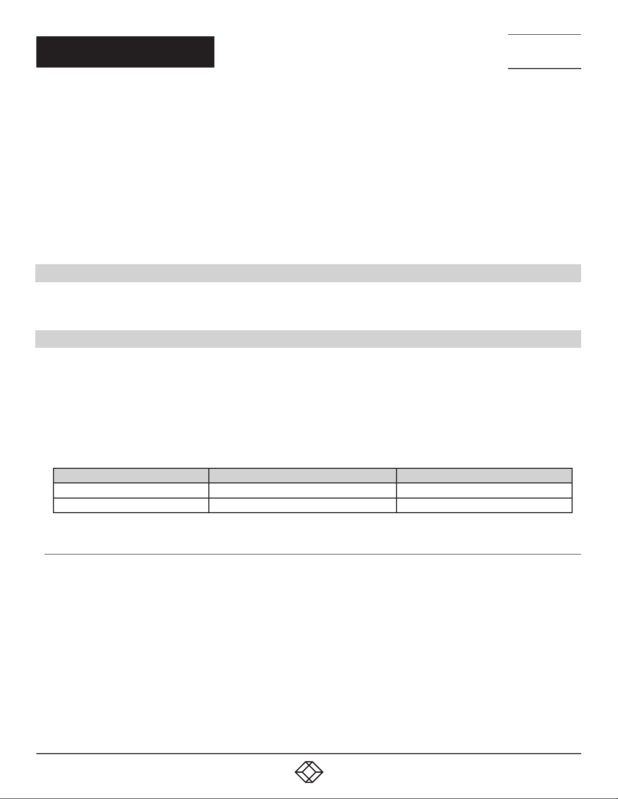
Connect the Host Link and Slave Link using the Extension Cable provided.
FIGURE 5-1.
The correct way to insert the cable is to have the release tab facing away from the card. The rectangular connector needs to be fully
inserted into the card until a denite click can be heard. This locks the cable in place. Failure to lock the connector in place can result
in the Extension Cable becoming separated from the card and the link between chassis being lost.
TECHNICAL
SUPPORT
1. 8 7 7. 8 7 7. 2 2 69
FIGURE 5-2.
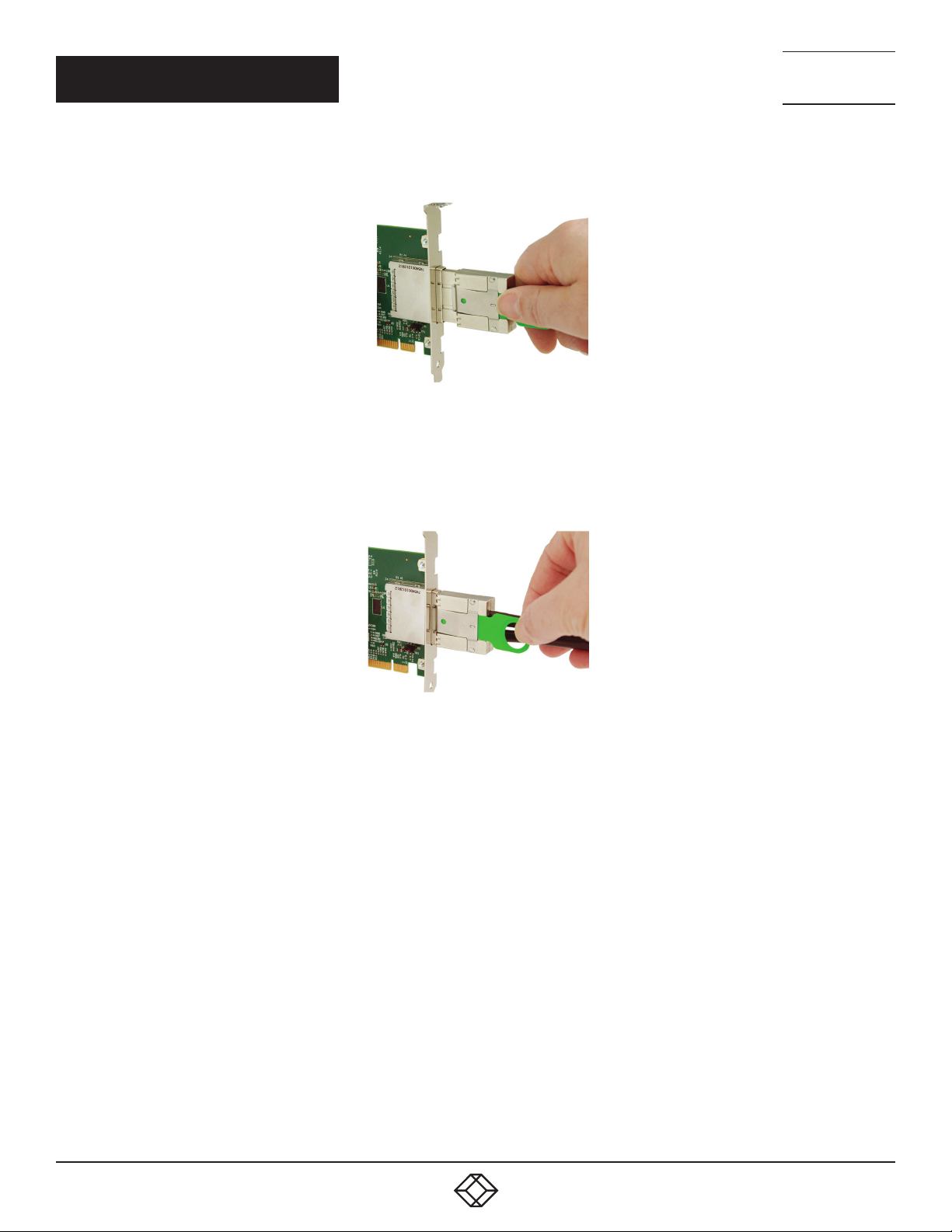
To remove the connector, gently pull the ring pull tab to unlock the connector from the card then slide the connector out fully.
Normal copper cable handling precautions should be observed to avoid tight loops or kinks in the extension cable.
If more than one expansion chassis is supplied, ensure the cards are paired correctly by connecting the cards labelled “Link1” together,
the pair labeled “link2” together and so on. If this is not possible, i.e. the expansion chassis are shipped separately and the cards are not
labeled, connect the cards using the extension cables provided and re-install the driver install package to reset the pairings.
30
1. 8 77. 8 77. 226 9 BLACKBOX.COM
 Loading...