

Page 1
USER MANUAL
V WP-10 6 0
RADIAN
1000
SERIES
24/7 TECHNICAL SUPPORT AT 1.877.877.2269 OR VISIT BLACKBOX.COM
RADIAN VIDEO
WALL PROCESSOR
Page 2

NEED HELP?
LEAV E TH E TEC H TO US
LIVE 24/7
TABLE OF CONTENTS
TECHNICAL
SUPPORT
1. 8 7 7. 8 7 7. 2 2 6 9
SAFETY .............................................................................................................................................................................................. 2
Safety Precautions ......................................................................................................................................................................................... 2
QUICK START GUIDE ......................................................................................................................................................................... 5
STEP 1: Keyboard and Mouse ....................................................................................................................................................................... 5
STEP 2: Connect to a Network (Optional) .................................................................................................................................................... 6
STEP 3: Connect Input Source ...................................................................................................................................................................... 6
STEP 4: Connect Control Screen (Optional) and Monitors ......................................................................................................................... 7
STEP 5: Powering On the System .................................................................................................................................................................8
®
STEP 6: Windows
STEP 7: Activate Windows 7 .......................................................................................................................................................................... 9
STEP 8: Display Setup .................................................................................................................................................................................. 10
STEP 9: Radian Video Wall Manager ..........................................................................................................................................................11
1. SPECIFICATIONS ......................................................................................................................................................................... 14
7 Setup ............................................................................................................................................................................ 9
2. OVERVIE W .................................................................................................................................................................................... 15
2.1 Introduction .............................................................................................................................................................................................15
2.2 Features .................................................................................................................................................................................................. 15
2.3 What’s Included ......................................................................................................................................................................................15
2.4 Hardware Description ............................................................................................................................................................................16
2.4.1 Chassis ............................................................................................................................................................................................16
2.4.2 Compatible Input/Output Cards ...................................................................................................................................................................17
3. CABLING ...................................................................................................................................................................................... 18
3.1 Connecting the Keyboard and Mouse .................................................................................................................................................. 18
3.2 Connecting to a Network (Optional) ..................................................................................................................................................... 18
3.3 Connecting Input Sources ..................................................................................................................................................................... 19
3.4 Connect Monitors and Control Screen (Optional) ...............................................................................................................................19
3.4.1 Screen Order ...................................................................................................................................................................................19
3.4.2 Connecting the Control Screen (Optional) .................................................................................................................................................. 21
3.4.3 How to Disable the Control Screen ..............................................................................................................................................................21
3.5 Connecting Power Cables .....................................................................................................................................................................22
4. OPERATION .................................................................................................................................................................................. 23
4.1 Switching On ........................................................................................................................................................................................... 23
4.2 Initial System Boot on Delivery ............................................................................................................................................................. 24
4.2.1 Select Language Pack ....................................................................................................................................................................24
4.2.2 Select Country and Region ............................................................................................................................................................................24
4.2.3 Names and Password .....................................................................................................................................................................................25
4.2.4 Enter the Product Key .....................................................................................................................................................................................25
4.2.5 System Backup .................................................................................................................................................................................................25
4.3 Opening Radian Video Wall Manager ................................................................................................................................................... 26
4.4 Displaying Video Captures ....................................................................................................................................................................26
2
1. 87 7.8 7 7. 2 26 9 BLACKBOX.COM
Page 3

NEED HELP?
LEAV E TH E TEC H TO US
LIVE 24/7
TABLE OF CONTENTS
TECHNICAL
SUPPORT
1. 8 7 7. 8 7 7. 2 2 6 9
5. SOFTWARE................................................................................................................................................................................... 28
5.1 Radian Video Wall Manager ...................................................................................................................................................................28
5.2 Radian Video Wall Manager — Features and Tools .............................................................................................................................28
5.3 Radian Video Wall Manager Software .................................................................................................................................................. 29
5.4 Software Utilities .................................................................................................................................................................................... 32
6. TECHNICAL SUPPORT ................................................................................................................................................................ 33
6.1 Contacting Black Box .............................................................................................................................................................................33
6.2 Shipping and Packaging ........................................................................................................................................................................33
7. MAINTENANCE ............................................................................................................................................................................ 34
Filter Maintenance ........................................................................................................................................................................................ 34
APPENDIX A: ADVANCED USERS .................................................................................................................................................. 35
A.1 Installing CODEC Packs to Play Video ................................................................................................................................................35
A.2 Firmware Updates..................................................................................................................................................................................35
A.3 Restoring to Factory Settings ............................................................................................................ ...................................................35
A.3.1 Selecting a Boot Device .................................................................................................................................................................35
A.3.2 Reactivate Windows .......................................................................................................................................................................36
A.3.3 Install Display Drivers and Software .............................................................................................................................................36
APPENDIX B: REGULATORY INFORMATION ................................................................................................................................ 37
B.1 FCC IC and RFI Statements ...................................................................................................................................................................37
B.2 NOM Statement .....................................................................................................................................................................................38
DISCLAIMER/ TRADEMARKS USED IN THIS MANUAL ............................................................................................................... 39
Disclaimer .....................................................................................................................................................................................................39
Trademarks Used in this Manual.................................................................................................................................................................39
1. 87 7.8 7 7. 2 26 9 BLACKBOX.COM
3
Page 4

NEED HELP?
LEAV E TH E TEC H TO US
LIVE 24/7
SAFETY
SAFETY PRECAUTIONS
To prevent damage to your Radian 6-Slot Chassis or injury to personnel operating the equipment, please read the following safety
precautions prior to operation. These instructions should be made available to all those who will use and operate the Chassis.
TECHNICAL
SUPPORT
1. 8 7 7. 8 7 7. 2 2 6 9
POWER SUPPLY
All Radian products require a power supply. This power supply must be disconnected when equipment is being upgraded or
relocated.
CABLES
Do not expose cables to any liquids; doing so may cause a short circuit that could damage the equipment. Do not place heavy
objects on top of any cables as this can cause damage and possibly lead to exposed live wires.
VENTILATION
All computer equipment should be located in a well ventilated area. All ventilation holes on the computer casing must be kept clear
of any obstruction at all times. Failure to do so will result in the system overheating and damaging your equipment.
WORKING ENVIRONMENT
The equipment should be located in an environment free from dust, moisture and extreme changes in temperature and should be
placed on a stable and solid work surface. Liquids (hot/cold drinks etc) should not be placed near the equipment as spillage could
cause serious damage.
GAS/FLAMMABLE LIQUIDS
Electronic equipment should never be used in the presence of gas or any flammable liquid, doing so could result in an explosion or
serious fire.
SMOKE/UNUSUAL SMELLS
If you notice smoke or unusual smells being emitted from your system, turn off and unplug the system from the power supply.
The system should then be passed to a qualified technician for inspection. Continued operation could result in personal injury and
damage to property.
MAINTENANCE
Apart from what is detailed in this user guide, maintenance should only be carried out by competent technicians. Any Black Box
plug-in cards that are physically damaged should be returned to Black Box for repair using Black Box RMA procedures.
REPLACABLE BATTERIES
CAUTION: Risk of explosion if batteries are replaced by an incorrect type. Dispose of used batteries according to the local laws/
regulations and manufacturer’s instructions.
4
1. 87 7.8 7 7. 2 26 9 BLACKBOX.COM
Page 5
NEED HELP?
LEAV E TH E TEC H TO US
LIVE 24/7
QUICK START GUIDE
TECHNICAL
SUPPORT
1. 8 7 7. 8 7 7. 2 2 6 9
A version of the Quick Start Guide is included below and on the following pages for your convenience.
Each Black Box Radian system is custom built to order, so the components, number and type of input and output cards will differ
from system to system.
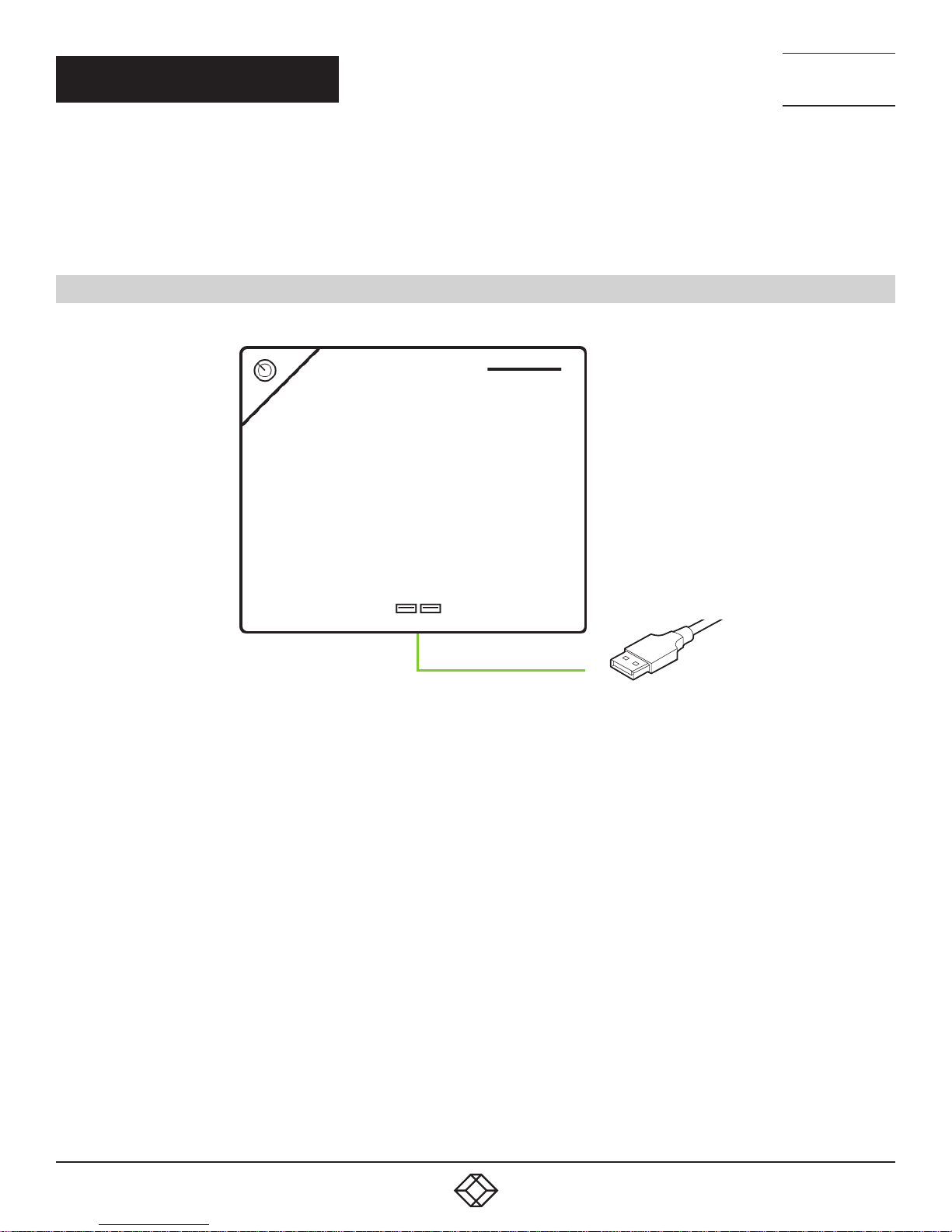
STEP 1: KEYBOARD AND MOUSE
Connect the keyboard and mouse to USB Ports.
FIGURE 1. CONNECT KE YBOARD AND MOUSE
1. 87 7.8 7 7. 2 26 9 BLACKBOX.COM
5
Page 6
QUICK START GUIDE
NEED HELP?
LEAV E TH E TEC H TO US
LIVE 24/7
TECHNICAL
SUPPORT
1. 8 7 7. 8 7 7. 2 2 6 9
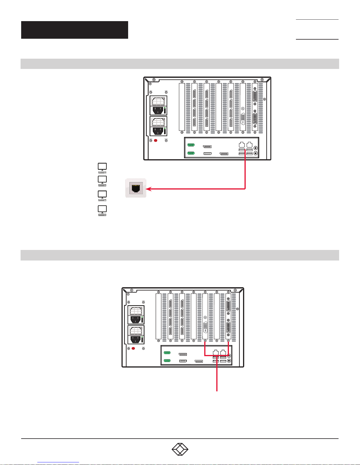
STEP 2: CONNECT TO A NETWORK (OPTIONAL)
FIGURE 2. CONNECT TO A NETWORK (OPTIONAL)
STEP 3: CONNECT TO AN INPUT SOURCE
As each system is custom built, the number and type of inputs will differ from system to system.
Input Connectors
FIGURE 3. CONNECT TO AN INPUT SOURCE
6
1. 87 7.8 7 7. 2 26 9 BLACKBOX.COM
Page 7
NEED HELP?
LEAV E TH E TEC H TO US
LIVE 24/7
QUICK START GUIDE
TECHNICAL
SUPPORT
1. 8 7 7. 8 7 7. 2 2 6 9
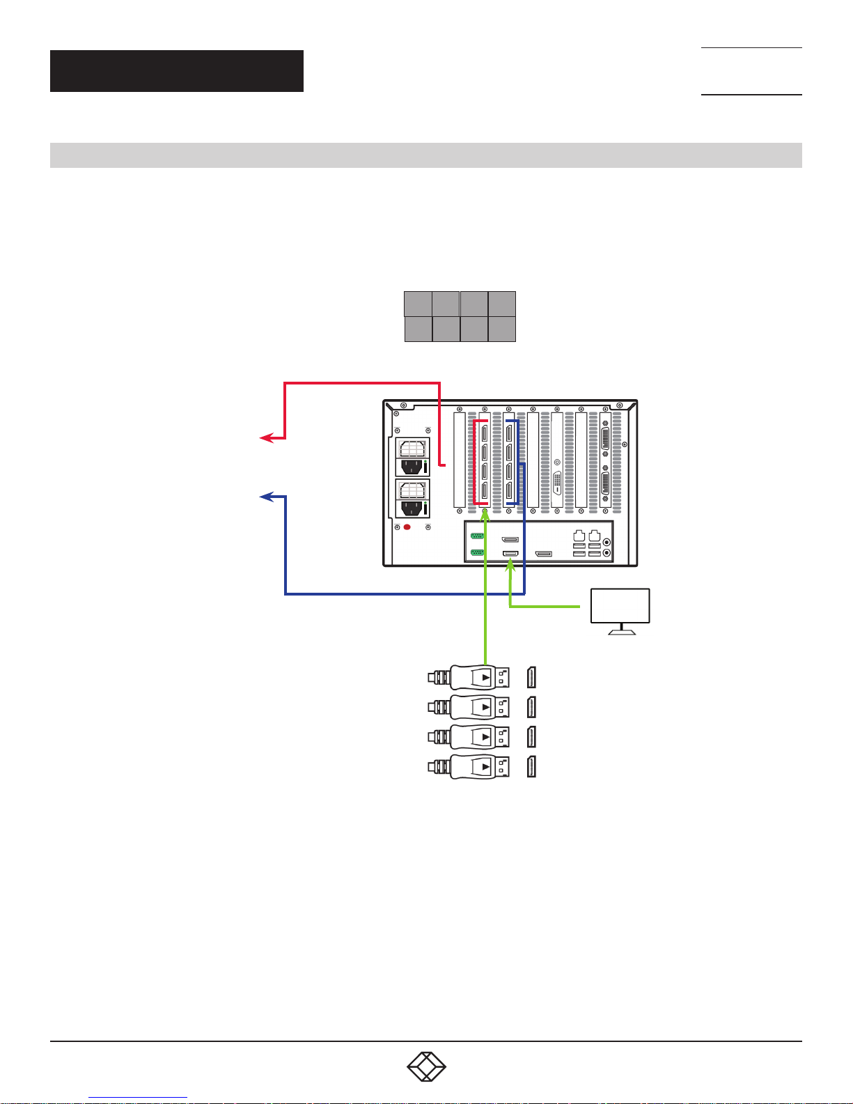
STEP 4: CONNECT A CONTROL SCREEN (OPTIONAL) AND MONITORS
Many of our wall controllers are configured to use a control screen (Internal Graphics Device) prior to leaving the factory.
If required, connect the control screen to the motherboard as shown below. If a control screen is not required, you will need
to change the BIOS settings.
4 x 2 Video Wall
MONITOR 1
MONITOR 2
MONITOR 3
MONITOR 4
MONITOR 5
MONITOR 6
MONITOR 7
MONITOR 8
1
5
3 4
2
7
6
8
1
4
CONTROL SCREEN
(OPTIONAL)
FIGURE 4. CONNECT TO A CONTROL SCREEN (OPTIONAL) AND MONITORS
CONNECT GRAPHIC OUTPUTS TO
MONITORS USING DISPLAYPORT CABLES.
1. 87 7.8 7 7. 2 26 9 BLACKBOX.COM
(NOT SUPPLIED)
7
Page 8
QUICK START GUIDE
STEP 5: POWERING ON THE SYSTEM
Connect the power cable, then plug into and turn on the power supply.
Switch on the system.
POWER
SWITCH
NEED HELP?
LEAV E TH E TEC H TO US
LIVE 24/7
TECHNICAL
SUPPORT
1. 8 7 7. 8 7 7. 2 2 6 9
FIGURE 5. SWITCH ON THE SYSTEM
8
1. 87 7.8 7 7. 2 26 9 BLACKBOX.COM
Page 9
QUICK START GUIDE
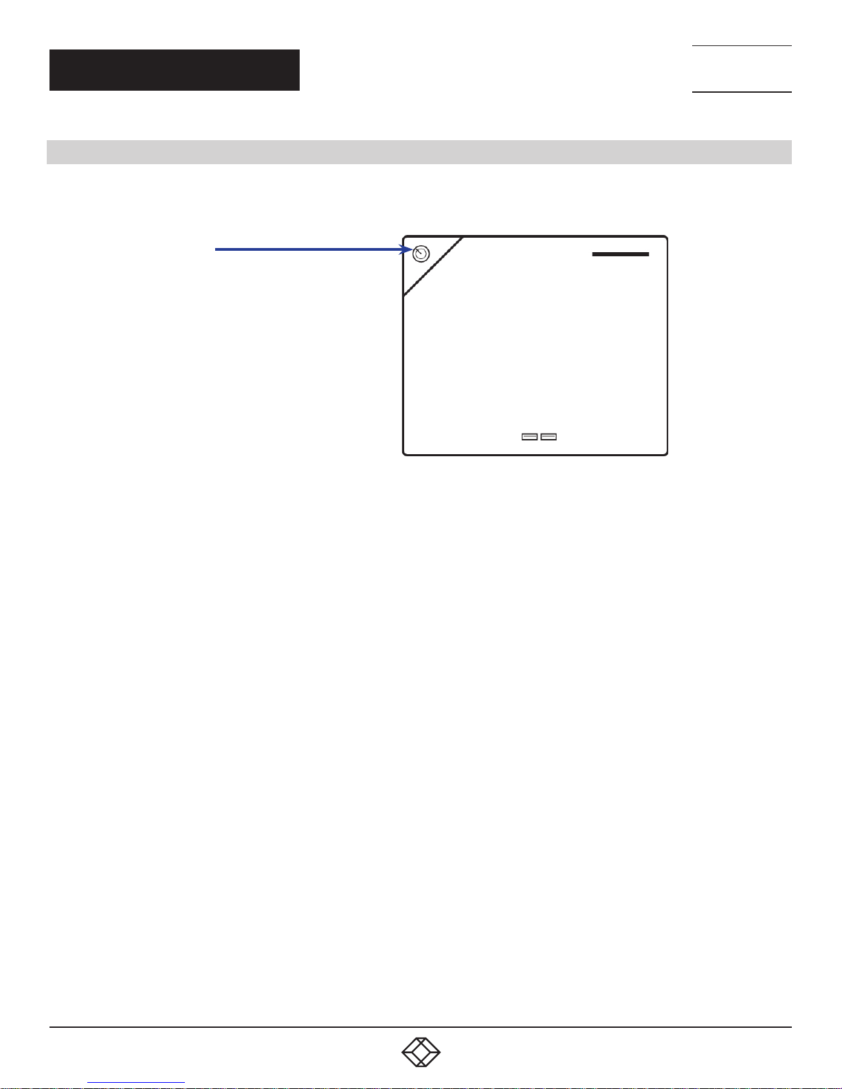
STEP 6: WINDOWS 7 SETUP
The Product key is
located behind the front
panel. Gently pull away
the front panel for access
NEED HELP?
LEAV E TH E TEC H TO US
LIVE 24/7
TECHNICAL
SUPPORT
1. 8 7 7. 8 7 7. 2 2 6 9
We recommend that you use only Internet-standard characters in the computer name. The standard characters are the numbers
0 through 9, upper and lower-case letters from A through Z and the hyphen character. Computer names cannot consist entirely
of numbers, contain spaces or use special characters such as: < > ; : “ ?* + = \ | ? ,.
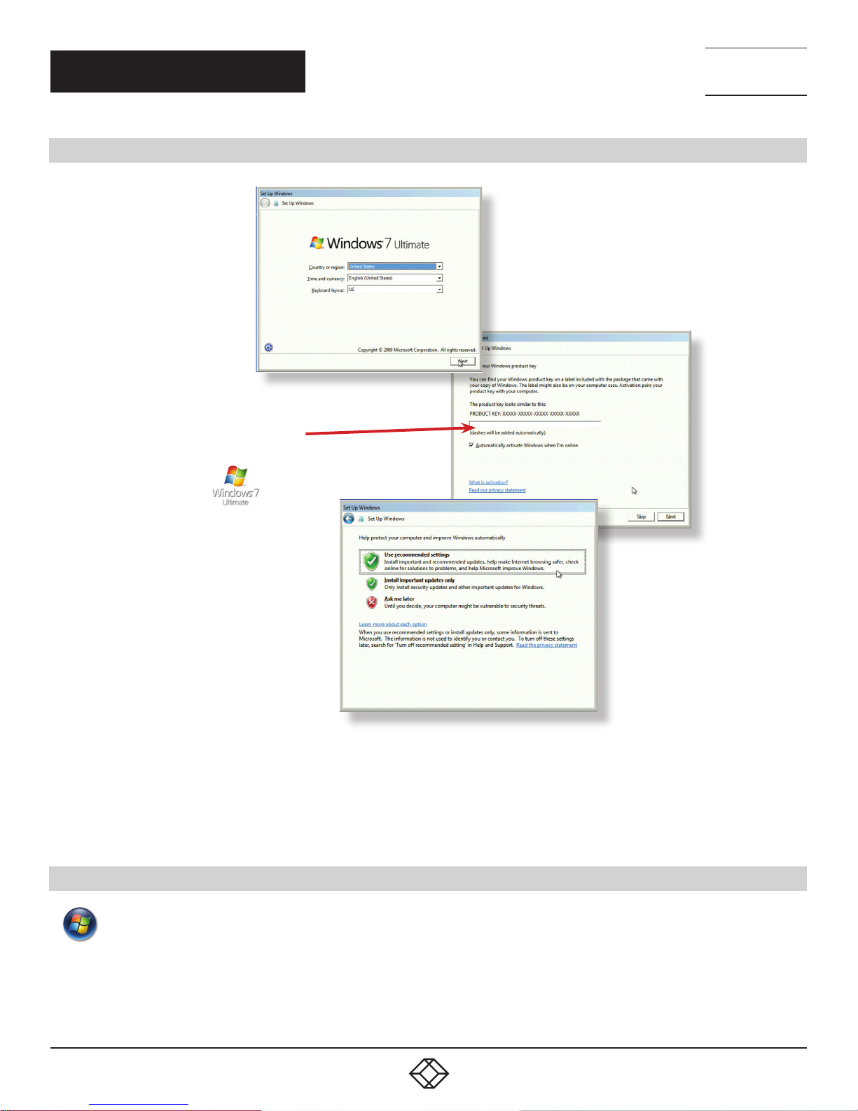
STEP 7: ACTIVATE WINDOWS 7
Start | Computer | Properties | Activate Windows now.
Select the appropriate method available.
To view the product key, gently pull away the front panel of the 6-Slot Chassis. The front panel is held in place with a series
of magnetic points.
FIGURE 6. WINDOWS 7 SETUP
1. 87 7.8 7 7. 2 26 9 BLACKBOX.COM
9
Page 10
NEED HELP?
LEAV E TH E TEC H TO US
LIVE 24/7
QUICK START GUIDE
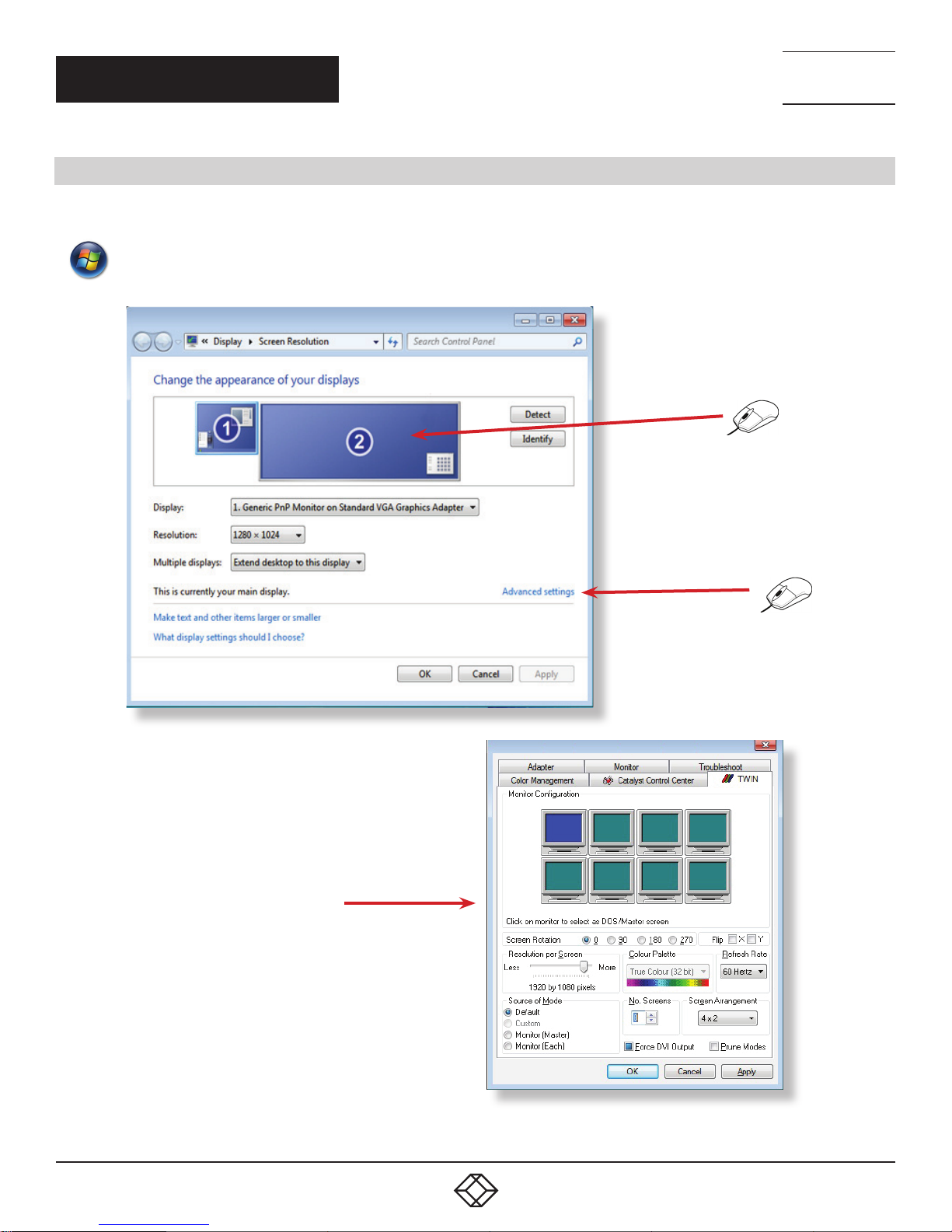
STEP 8: DISPLAY SETUP
All Radian wall controllers have pre-configured settings for the wall layout and screen resolution. Change settings using the TWIN
tab.
Start | Control Panel | Appearance and Personalization | Adjust screen resolution.
TECHNICAL
SUPPORT
1. 8 7 7. 8 7 7. 2 2 6 9
1
2
3
10
FIGURE 7. DISPLAY SETUP
1. 87 7.8 7 7. 2 26 9 BLACKBOX.COM
Page 11

NEED HELP?
LEAV E TH E TEC H TO US
LIVE 24/7
QUICK START GUIDE
TECHNICAL
SUPPORT
1. 8 7 7. 8 7 7. 2 2 6 9
STEP 9: RADIAN VIDEO WALL MANAGER
Start | All Programs | Radian Video Wall Manager - Server
Before opening the Client interface, you will need to start the Server by clicking on it in the Programs menu. The Radian Video Wall
Manager Client can only detect servers that are running.
Start | All Programs | Radian Video Wall Manager - Client
When you open Radian Video Wall Manager for the first time, you will be prompted to take a Quick Start Tour of the application. We
strongly recommend that you take the tour before using the application.
1. 87 7.8 7 7. 2 26 9 BLACKBOX.COM
11
Page 12
QUICK START GUIDE
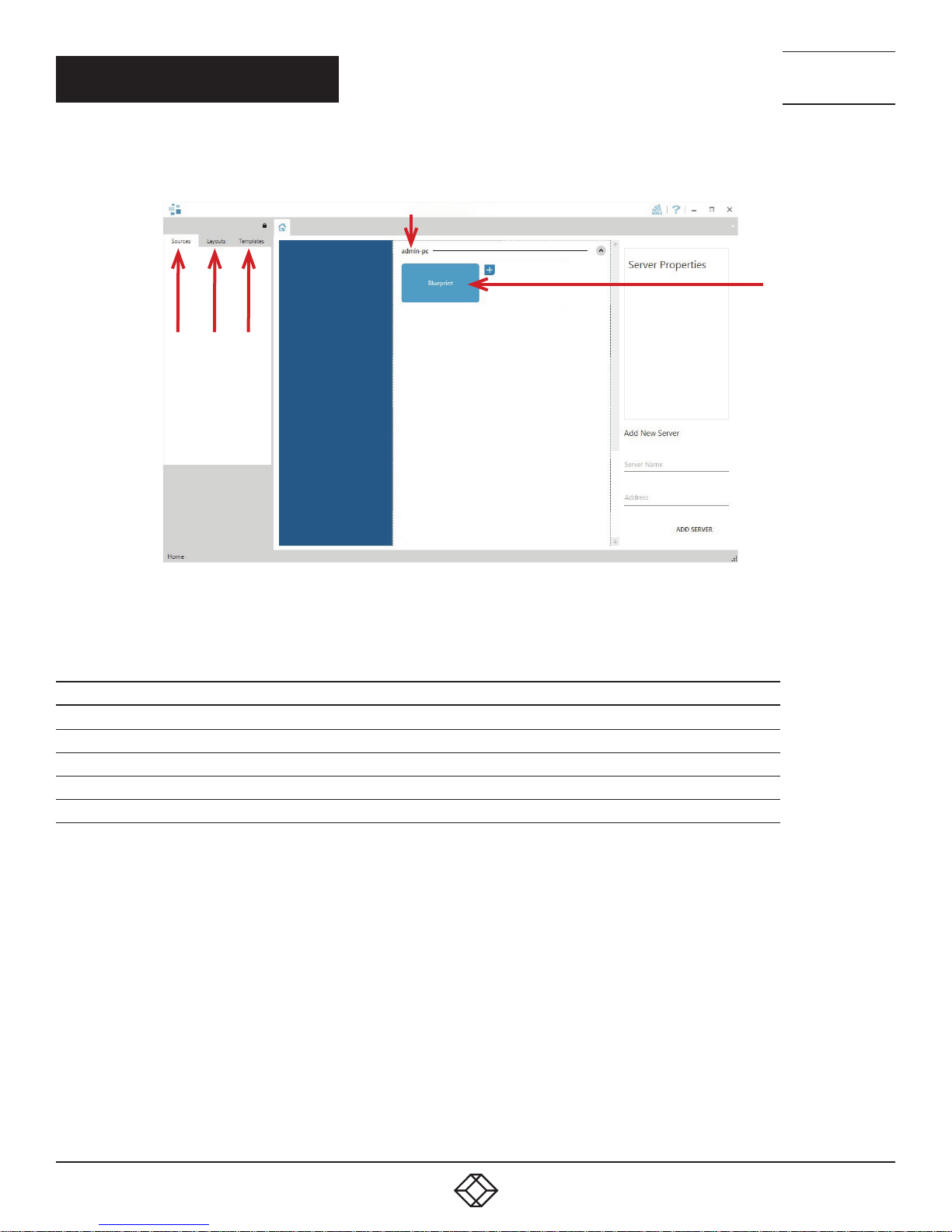
THE RADIAN VIDEO WALL MANAGER - USER INTERFACE
1
3 4 5
NEED HELP?
LEAV E TH E TEC H TO US
LIVE 24/7
TECHNICAL
SUPPORT
1. 8 7 7. 8 7 7. 2 2 6 9
2
FIGURE 8. WALL CONTROL 10 USER INTERFACE
TABLE 1. RADIAN VIDEO WALL MANAGER USER INTERFACE COMPONENTS
NUMBER IN FIGU RE 8 DESCRIPTION
1 Indicates the server you are connected to
2 A representation of the display wall associated with the server
3 Sources Tab — Displaying all the sources connected to the server for use on your display wall
4 Layouts Tab — Used to save, recall and share display wall layout information
5 Templates Tab — Use templates to assist in the design of specific display wall layouts
12
1. 87 7.8 7 7. 2 26 9 BLACKBOX.COM
Page 13

QUICK START GUIDE
CLICK ON THE DISPLAY WALL REPRESENTATION TO OPEN THE DISPLAY WALL TAB
NEED HELP?
LEAV E TH E TEC H TO US
LIVE 24/7
TECHNICAL
SUPPORT
1. 8 7 7. 8 7 7. 2 2 6 9
Display Wall
Tab
Display Wall
Representation
Sources
FIGURE 9. DISPLAY WALL REPRESENTATION
When opened, the display wall tab shows a live representation of the physical wall and the sources available to display on it. To place
a source on a display wall, simply click on the required source in the sources tab and drag it onto the display wall representation.
The application help file contains videos explaining how multiple sources can be selected, how to use and create templates and how
to save, recall and share layout files.
1. 87 7.8 7 7. 2 26 9 BLACKBOX.COM
13
Page 14

CHAPTER 1: SPECIFICATIONS
TABLE 1-1. RADIAN 6-SLOT CHASSIS SPECIFICATIONS
SPECIFICATION DESCRIPTION
(2) Serial ports,
(2) DisplayPort Control Screen outputs, (1) HDMI
System I/O
Processor Standard: Core™ i5
System Memory Standard: 8 GB DDR
Operating System WIndows® 7 Ultimate
Power Supply 110 to 240 V, 500 Watts
Hard Drive Standard: Single 240 GB SSD
Dimensions 6.9"H x 9.8"W x 12.5"D (17.5 x 25 x 32 cm)
Weight
Approvals FCC, CE, RoHS
(4) USB 3.0 ports,
(2) USB 2.0 ports,
(2) Intel® 10/10 0/1000 Ethernet ports
4
Unit: 22 to 33 lb. (10 to 15 kg);
Shipping: 33 to 44 lb. (15 to 20 kg)
NEED HELP?
LEAV E TH E TEC H TO US
LIVE 24/7
TECHNICAL
SUPPORT
1. 8 7 7. 8 7 7. 2 2 6 9
14
1. 87 7.8 7 7. 2 26 9 BLACKBOX.COM
Page 15

NEED HELP?
LEAV E TH E TEC H TO US
LIVE 24/7
CHAPTER 2: OVERVIEW
2.1 INTRODUCTION
Build systems can include a large number of video inputs and IP streams. These video inputs and IP streams can be quickly and
easily delivered to a large, multi-screen video wall.
The compact Radian 6-Slot Chassis is ideal for command and control rooms where server space is nonexistent or limited.
TECHNICAL
SUPPORT
1. 8 7 7. 8 7 7. 2 2 6 9
2.2 FEATURES
Works with different Intel processors, hard drive sizes and specifications, memory configurations, and software
Small footprint
Quiet deployment means the chassis is suitable for use outside of a server room and in more public areas
Uses a high-performance enterprise-grade motherboard that connects to a Radian PCIe backplane
PCIe backplane contains six half-length PCIe slots for use with compatible Radian cards, including video capture, image graphics,
and IP decoding cards
2.3 WHAT’S INCLUDED
Your package should contain the following items. If anything is missing or damaged, contact Black Box Technical Support
at 877-877-2269 or info@blackbox.com
Radian 6-Slot Chassis
Quick Start Guide
NOTE: Any PCIe cards you ordered will arrive installed in your Chassis.
1. 87 7.8 7 7. 2 26 9 BLACKBOX.COM
15
Page 16

CHAPTER 2: OVERVIEW
2.4 HARDWARE DESCRIPTION
2 .4 .1 C H A SS I S
Figures 2-1 and 2-2 show the front and back panels of the 6-Slot Chassis. Table 2-1 describes its components.
1
NEED HELP?
LEAV E TH E TEC H TO US
LIVE 24/7
TECHNICAL
SUPPORT
1. 8 7 7. 8 7 7. 2 2 6 9
R1
R2
2
FIGURE 2-1. FRONT PANEL OF THE 6-SLOT CHASSIS
R3
FIGURE 2-2. BACK PANEL OF THE 6-SLOT CHASSIS
16
R4
1. 87 7.8 7 7. 2 26 9 BLACKBOX.COM
Page 17

CHAPTER 2: OVERVIEW
TABLE 2-1. RADIAN 6-SLOT CHASSIS COMPONENTS
NUMBER IN FIGU RES 2-1 AND 2-2 DESCRIPTION
1 Power, ON/OFF
2 USB ports
R1 Power connector
R2 Ethernet ports
R3 USB ports
R4 HDMI/DisplayPort outputs
2.4.2 COMPATIBLE INPUT/OUTPUT CARDS
TABLE 2-2. COMPATIBLE CARDS FOR USE WITH THE RADIAN 6-SLOT CHASSIS
NEED HELP?
LEAV E TH E TEC H TO US
LIVE 24/7
TECHNICAL
SUPPORT
1. 8 7 7. 8 7 7. 2 2 6 9
PRODUCT CODE INPUTS SIGNAL FORMAT
Video Capture Cards
VCC-DP-2 (2) channels DisplayPort 4K card DisplayPort 4K
VCC-HD-4-D (4) channels HD capture card with DVI splitter cables HD, DVI
VCC-HD-4-H (4) channels HD capture card with HDMI splitter cables HD, HDMI
VCC-SDI-4 (4) channels 3G-SDI capture card 3G-SDI
VCC-SD-HD-3 (2) HD channels + (1) SD channel HD, SD
VCC-STREAM (2) 100/1000 Mbps Ethernet ports* H.264
Video Graphics Cards
VGC-DP-4 4-port DisplayPort graphics card DisplayPort
VGC-DP-4-H 4-port DisplayPort graphics card with HDMI adapters DisplayPort, HDMI
VGC-DP-4-D 4-port DisplayPort graphics card with DVI adapters DisplayPort, DVI
*For the best quality image, you should have a 1000-Mbps connection.
1. 87 7.8 7 7. 2 26 9 BLACKBOX.COM
17
Page 18

NEED HELP?
LEAV E TH E TEC H TO US
LIVE 24/7
CHAPTER 3: CABLING
3.1 CONNECTING THE KEYBOARD AND MOUSE
The keyboard and mouse supplied with your system both have a USB interface. Identify vacant USB ports on the chassis and plug
them in.
NOTE: The locations of the USB ports are identifed in the previous chapter.
3.2 CONNECTING TO A NETWORK (OPTIONAL)
The optional Wall Control 10 and Radian Wall Control software enable the user to operate and manage the video wall display
remotely, via a network. The 6-Slot Chassis has two Ethernet ports; plug your network cable (not supplied) into any port and
connect the 6-Slot Chassis to the LAN, as shown below.
TECHNICAL
SUPPORT
1. 8 7 7. 8 7 7. 2 2 6 9
FIGURE 3-1. CONNECT TO A NETWORK (OPTIONAL)
CAUTION: Network ports have a potential vulnerability. If your system is working in a secure environment, you probably don’t need
to worry about unauthorized access to the LAN port. If your system is on a network that is generally accessible, you will probably
want to restrict access to the ports.
18
1. 87 7.8 7 7. 2 26 9 BLACKBOX.COM
Page 19

NEED HELP?
LEAV E TH E TEC H TO US
LIVE 24/7
CHAPTER 3: CABLING
TECHNICAL
SUPPORT
1. 8 7 7. 8 7 7. 2 2 6 9
3.3 CONNECTING INPUT SOURCES
Each Radian 6-Slot Chassis may differ depending on the number and models of input cards installed. The build log document
shipped with your system will enable you to establish which input cards you have installed.
Contained within the product documentation folder is the main Radian user manual. For detailed information on specific cards,
please consult this manual. It is located on the Recovery Media supplied with your system.
CABLE HANDLING
CAUTION: Take great care when connecting cables. Ensure the cable connectors are the correct type for the connector on the cards.
Push the cable connector on squarely, there is no requirement to force the connector in place. Poor cable handling could result in
damaged pins in the cable connector, this in turn could cause serious and irreversible damage to the printed circuit board on the card.
Any damage caused this way is not covered under the warranty.
3.4 CONNECTING MONITORS AND CONTROL SCREEN (OPTIONAL)
Each system can support any number of screens from 4 to 16 depending on hardware installed, however the following information
is a guide based on a 12 screen 4x3 video wall system.
The number of graphics cards in your system determines how many screens will be available on your video wall. The graphics
cards (VGC-DP-4, VGC-DP-4-H or VGC-DP-4-D) each support a maximum of 4 screens, one output per screen.
3.4.1 SCREEN ORDER
The screen order is determined by where the graphics cards are installed in the system. The card installed furthest right (looking
from the rear) is card 1, which is the first card to be initialized and will generate the desktop for the top left monitor on the video
wall plus the 3 adjacent screens. The second card drives the next four screens and so on. Each graphics card has 4 connectors,
numbered as follows:
VGC-DP-4, VGC-DP-4-H or VGC-DP-4-D
Four Port Graphics Card
1
2
3
4
FIGURE 3-2. SCREEN ORDER SELECTION
Output 1
Output 2
Output 3
Output 4
Connectors:
4 x DisplayPort
Supports:
Up to 4 cards per system (16 display channels)
Cables/Adapters:
VGC-DP-4- None
VGC-DP-4-D - 4 x DVI adapters
1. 87 7.8 7 7. 2 26 9 BLACKBOX.COM
19
Page 20

NEED HELP?
LEAV E TH E TEC H TO US
LIVE 24/7
CHAPTER 3: CABLING
The following illustration shows how to connect twelve monitors to three VGC-DP-4 or VGC-DP-4-D graphics cards to create a
twelve-screen video wall.
Connect the graphic outputs to your monitors using DisplayPort cables (not supplied).
TECHNICAL
SUPPORT
1. 8 7 7. 8 7 7. 2 2 6 9
1 2 3 4
Corresponding
Graphics Outputs
5
9
FIGURE 3-3. TWELVE-SCREEN DISPLAY WALL
6
7
10 11 12
5
1
2
6
3
7
4
8
8
9
FIGURE 3-4. CORRESPONDING GRAPHICS OUTPUTS ON THE 6-SLOT CHASSIS
TABLE 3-1. GRAPHICS OUTPUTS
NUMBER IN FIGU RES 3-3 AND 3-4 DESCRIPTION
1–4 Output connectors on card 1 for screens 1–4
5–8 Output connectors on card 2 for screens 5–8
9–12 Output connectors on card 3 for screens 9–12
20
1. 87 7.8 7 7. 2 26 9 BLACKBOX.COM
Page 21

NEED HELP?
LEAV E TH E TEC H TO US
LIVE 24/7
CHAPTER 3: CABLING
TECHNICAL
SUPPORT
1. 8 7 7. 8 7 7. 2 2 6 9
3.4.2 CONNECTING THE CONTROL SCREEN (OPTIONAL)
Most Radian systems are configured to boot from the onboard graphics device therefore there may be a requirement to connect
a control screen. The control screen is a standalone monitor that is separate from the monitors on the display wall. The control
screen is configured as the Primary monitor in the Windows
monitor.
Connect the control screen as follows:
Onboard Graphics Device.
HDMI/DisplayPort
®
Display Settings and the display wall is configured as the Secondary
Control
Screen
FIGURE 3-5. CONTROL SCREEN CONNECTION
3.4.3 HOW TO DISABLE THE CONTROL SCREEN
If you do not require a control screen then you should disable the integrated graphics in the system BIOS.
To enter the system BIOS press F2 or the delete button on boot:
Select the Advanced page.
Select Chipset Configuration.
For the Primary Graphics Adapter select “PCI Express”
Press F10 to save the settings and exit from the BIOS.
1. 87 7.8 7 7. 2 26 9 BLACKBOX.COM
21
Page 22

NEED HELP?
LEAV E TH E TEC H TO US
LIVE 24/7
CHAPTER 3: CABLING
3.5 CONNECTING POWER CABLES
Ensure your cable is fully inserted into the power supply socket, failure to do so could result in the cable becoming dislodged and
the system inadvertently shutting down.
Insert Power
Cable
TECHNICAL
SUPPORT
1. 8 7 7. 8 7 7. 2 2 6 9
FIGURE 3-6. CONNECTING THE POWER CABLE
CAUTION: Only use the power cables supplied with your system. For advice on replacements, contact Black Box at 877-877=2269
or info@blackbox.com.
22
1. 87 7.8 7 7. 2 26 9 BLACKBOX.COM
Page 23

NEED HELP?
LEAV E TH E TEC H TO US
LIVE 24/7
CHAPTER 4: OPERATION
TECHNICAL
SUPPORT
1. 8 7 7. 8 7 7. 2 2 6 9
4.1 SWITCHING ON
When switching the system on for the first time you will need to complete the initial system boot steps as described in Initial
System Boot on Delivery below.
SWITCHING ON THE SYSTEM
Make sure the power cable is correctly connected, then turn on the 6-Slot Chassis.
POWER
SWITCH
FIGURE 4-1. SWITCH ON THE SYSTEM
Turn on the main system power switch located on the front panel.
The BIOS and boot messages will be displayed on the control screen (if connected) as the system boots. Once the system boot up
is complete, the display wall will open up into a Windows desktop.
1. 87 7.8 7 7. 2 26 9 BLACKBOX.COM
23
Page 24

NEED HELP?
LEAV E TH E TEC H TO US
LIVE 24/7
CHAPTER 4: OPERATION
4.2 INITIAL SYSTEM BOOT ON DELIVERY
Once the system has been configured in the factory the operating system is resealed, meaning that when switching on the system
for the first time the operating system setup commences.
You will be prompted to enter information to set up your 6-Slot Chassis.
TECHNICAL
SUPPORT
1. 8 7 7. 8 7 7. 2 2 6 9
4.2.1 SELECT LANGUAGE PACK
You will now be prompted to set up your Windows 7 operating system starting with selecting the language option you require.
Language selection is the responsibility of the customer and is not part of the system pre-configuration prior to shipment.
Windows 7 language settings can be changed using Control Panel/Region and Language on the Keyboard and Languages tab.
Language packs are available to download as optional updates through Windows Update.
The following languages are pre-installed:
English (USA)
English (UK)
Simplified Chinese
French
German
Italian
Japanese
Polish
Portuguese (Brazilian)
Russian
Spanish
4.2.2 SELECT COUNTRY AND REGION
Use the dropdown menus to select the country and region, the time zone and currency and the keyboard layout. These localized
settings can be changed if required using the dialog in Control Panel/Region and Language.
FIGURE 4-2. DROPDOWN MENU FOR COUNTRY AND REGION
24
1. 87 7.8 7 7. 2 26 9 BLACKBOX.COM
Page 25

NEED HELP?
LEAV E TH E TEC H TO US
LIVE 24/7
CHAPTER 4: OPERATION
TECHNICAL
SUPPORT
1. 8 7 7. 8 7 7. 2 2 6 9
4.2.3 NAMES AND PASSWORD
Next you will be prompted to personalise your system by entering a user name, a computer name and a password.
It is recommended that only Internet standard characters are used in the computer name. The standard characters are the numbers
0 through to 9, upper and lower-case letters from A through to Z and the hyphen character. Computer names cannot consist entirely
of numbers, contain spaces or use special characters such as: < > ; : “ ?* + = \ | ? ,.
4.2.4 ENTER THE PRODUCT KEY
Next, you will be prompted to personalize your system by entering a user name, a computer name and a password.
It is recommended that only Internet standard characters are used in the computer name. The standard characters are the numbers
0 through 9, upper and lower-case letters from A through Z and the hyphen character. Computer names cannot consist entirely
of numbers, contain spaces or use special characters such as: < > ; : “ ?* + = \ | ? ,.
FIGURE 4-3. PRODUCT KEY SCREEN
Enter the Product key in the edit box. The Product Key is attached to the front panel of your system behind the filter housing. See
Chapter 7 for details on how to remove the filter housing.
Once the Product key has been entered, read and accept the license agreement.
4.2.5 SYSTEM BACKUP
We strongly recommend that you create some form of system recovery media using the MS Windows Backup and Restore Tool once
your system is up and running. This will enable you to restore your settings if problems occur.
Start | Control Panel | System and Security | Backup and Restore
1. 87 7.8 7 7. 2 26 9 BLACKBOX.COM
25
Page 26

NEED HELP?
LEAV E TH E TEC H TO US
LIVE 24/7
CHAPTER 4: OPERATION
4.3 OPENING RADIAN VIDEO WALL MANAGER
Radian Video Wall Manager is an optional video/display wall management software application specifically designed for Black Box
Radian Video Wall Processors. Radian Video Wall Manager consists of two separate elements that work together to enable you to
control the display wall, the Client (application) and the Server.
TECHNICAL
SUPPORT
1. 8 7 7. 8 7 7. 2 2 6 9
RADIAN VIDEO WALL MANAGER APPLICATION
The Radian Video Wall Manager Application should be installed on the machine that has been identified to control the display wall.
This could be any machine on the network including the machine driving the display wall. The application element of Radian Video
Wall Manager is used to control the position, size and properties of each window displayed on the Server machine.
RADIAN VIDEO WALL MANAGER SERVER
The Radian Video Wall Manager Server is used to display IP and application windows. The Server element of Radian Video Wall
Manager needs to be installed on the machine from which you wish to create IP and application windows. To open Radian Video
Wall Manager:
Start | All Programs | Radian Video Wall Manager
The Radian Video Wall Manager Start Menu offers two methods of opening the application, Radian Video Wall Manager and
Radian Video Wall Manager-My Computer.
RADIAN VIDEO WALL MANAGER — MY COMPUTER
Radian Video Wall Manager -My Computer refers to your system having both the Radian Video Wall Manager Application and the
Radian Video Wall Manager Server installed. Selecting Radian Video Wall Manager-My Computer will open the Radian Video Wall
Manager application window having activated both the Server and the Application. The application window will display all inputs
available in the system.
RADIAN VIDEO WALL MANAGER
Selecting Radian Video Wall Manager will launch the application window but will not connect to a Radian Video Wall Manager
Server. For more information regarding connecting to a Radian Video Wall Manager Server, consult the application help file.
4.4 DISPLAYING VIDEO CAPTURES
Once a connection to a Radian Video Wall Manager server has been established then windows can be created for display on
your video/display wall. Some video formats may not be supported, see Installing video CODECS in the Advanced User Chapter.
Windows can be created using the New menu or the application Toolbar.
NEW MENU
Displays options for each window type:
Preset Window
Vision Window
IP-Camera Window
26
1. 87 7.8 7 7. 2 26 9 BLACKBOX.COM
Page 27

NEED HELP?
LEAV E TH E TEC H TO US
LIVE 24/7
CHAPTER 4: OPERATION
TECHNICAL
SUPPORT
1. 8 7 7. 8 7 7. 2 2 6 9
Run an Application
TOOLBAR
The application Toolbar displays a list of the type of windows that can be opened, depending on the hardware you have installed in
your machine.
To open the required inputs:
Select the required input using the cursor and drag to a preferred position on the wall.
Double-click on the required input and the window will open, positioned at the top left of the display wall.
Open multiple inputs by pressing the shift key and clicking the required number of inputs with the mouse.
NOTE: A detailed summary of Radian Video Wall Manager software features can be found in Chapter 5, alternatively a
comprehensive help file system is available within the application, select Help | Contents.
1. 87 7.8 7 7. 2 26 9 BLACKBOX.COM
27
Page 28

NEED HELP?
LEAV E TH E TEC H TO US
LIVE 24/7
CHAPTER 5: SOFTWARE
5.1 RADIAN VIDEO WALL MANAGER
The Radian Video Wall Manager application is pre-installed and tested prior to shipment of your Radian 6-Slot Chassis, so no
installation of the software is required.
Radian Video Wall Manager offers real time management of small, medium and large scale display walls, it enables you to create
multiple walls that can all be controlled by a single wall controller system .
You can use Radian Video Wall Manager to interactively move, size and position local application windows, video capture and IPCamera windows. Radian Video Wall Manager allows you to save specific wall layouts as .dpl files enabling them to be shared with
other users and recalled when required.
TECHNICAL
SUPPORT
1. 8 7 7. 8 7 7. 2 2 6 9
5.2 RADIAN VIDEO WALL MANAGER — FEATURES AND TOOLS
LAYOUT FILES
Save, recall and share specific desktop configurations using layout files.
SOURCES
Sources are grouped by type or by location in the Sources Tab. All sources can be allocated search strings which enables users to
quickly find and display specific sources.
TEMPLATES
Templates are tools designed to assist in the creation of the layout of your display wall. Templates can be used to create visual
displays over numerous screens to enable you to showcase specific content to target audiences. A number of pre-defined
templates are available on the Template tab.
Three types of template are available:
Desktop Template - Allows you to create a template to cover the whole of your display wall.
Free Floating Template - A template can be placed on top of a video window. The template can be dragged anywhere on the wall
and re-sized.
Custom Templates - Design your own custom template and save it to the template library. It can then be used as a Desktop or
Free Floating template.
WALL CREATOR
Wall Creator enables you to create multiple walls from one single display wall. Each wall created can operate independently, having
its own sources and templates.
CAROUSEL
The Carousel function allows you to define a number of sources which a window will cycle through, allowing each input to be
viewed in turn for a specified duration. The edit panel allows you to set the duration of each source in the Carousel cycle and create
a buffer if required.
28
1. 87 7.8 7 7. 2 26 9 BLACKBOX.COM
Page 29

NEED HELP?
LEAV E TH E TEC H TO US
LIVE 24/7
CHAPTER 5: SOFTWARE
TECHNICAL
SUPPORT
1. 8 7 7. 8 7 7. 2 2 6 9
VIDEO AND IP WINDOW
Control over presenting captured video and IP camera streams on the display wall. Configure window properties including:
Position and size of windows
Aspect ratio enforcement
Show window borders
LOCAL APPLICATION WINDOWS
Support for controlling applications such as Internet Explorer or Microsoft Powerpoint. Applications can be opened direct from the
Radian Video Wall Manager Sources Tab.
AUDIO SUPPORT
Control digital and analog audio content associated with specific windows.
MULTI -WALL
Configure a single system to drive multiple walls.
5.3 RADIAN VIDEO WALL MANAGER SOFTWARE
The Radian Video Wall Manager software application is pre-installed and tested prior to shipment of your system, therefore no
installation of the software is required.
Radian Video Wall Manager displays the desktop of the machine that is being controlled. It allows you to remotely display
IP-Camera and Application windows across a network on another machine or locally on the same machine.
You can use Radian Video Wall Manager to interactively move, size and position application windows and control IP-Camera
windows by using the Windows Properties sheet. Radian Video Wall Manager also has a guide and grid function to aid the
positioning of windows on the display wall.
Radian Video Wall Manager allows you to save specific wall layouts as .lay files enabling them to be re-called when required.
There is an area of the application around the desktop where windows can be dragged allowing them to be manipulated without
being displayed on the video/display wall.
1. 87 7.8 7 7. 2 26 9 BLACKBOX.COM
29
Page 30

CHAPTER 5: SOFTWARE
ICONS DISPLAYED IN THE RADIAN VIDEO WALL MANAGER TOOLBAR
The Icons displayed in the application toolbar identify which type of source is available to each input:
TABLE 5-1. ICONS IN RADIAN VIDEO WALL MANAGER TOOLBAR
ICON DESCRIPTION
Composite source
S-Video source
Analog source
Component source
NEED HELP?
LEAV E TH E TEC H TO US
LIVE 24/7
TECHNICAL
SUPPORT
1. 8 7 7. 8 7 7. 2 2 6 9
DVI source
Dual-Link DVI source
DisplayPort source
SDI/HD-SDI/3G source
IP Camera source
If an icon is displayed with a green surround, this indicates the type of source being captured for that particular input.
RADIAN VIDEO WALL MANAGER — FEATURES AND TOOLS
Radian Video Wall Manager has a range of advanced features to enable you to manage your video/display wall either locally or
remotely over a network. The following list provides a brief summary of the features and tools contained within the application.
However, all the features and tools are documented in depth in the Radian Video Wall Manager help file that can be accessed
through the Help menu or by pressing F1 when the application is active.
LAYOUT FILES
Save and recall specific desktop configurations using layout files. Window properties including the position, size and any On Screen
Displays are also saved in layout files.
30
1. 87 7.8 7 7. 2 26 9 BLACKBOX.COM
Page 31

NEED HELP?
LEAV E TH E TEC H TO US
LIVE 24/7
CHAPTER 5: SOFTWARE
TECHNICAL
SUPPORT
1. 8 7 7. 8 7 7. 2 2 6 9
OFFLINE CONFIGURATION
The Radian Video Wall Manager offline layout editor allows layout files to be created and edited without physically displaying any
windows on the display wall. Radian Video Wall Manager can be connected offline on either the server machine or a machine
without any display wall hardware, for example a laptop.
An offline connection in Radian Video Wall Manager is initiated by opening a configuration file. This file must have been exported
from a server machine and will contain a snapshot of the hardware and software configuration on that machine.
IP WINDOW
This gives you control over presenting captured video and IP camera streams on the display wall. Configure window properties
including:
Position and size of windows
Aspect ratio enforcement
Exclude window borders and menu bar
Create on screen display captions
Control capture rate
APPLICATION WINDOWS
This gives you support for controlling applications such as Internet Explorer, Microsoft Powerpoint. Application can be opened
direct from the Radian Video Wall ManagerToolbar, through the Command Line Interface or from previously-saved layout files.
ON-SCREEN DISPLAY (OSD)
The highly-configurable OSD function enables the system to overlay bitmaps (not on all types of window) and text over IP-Camera
windows. Add descriptions and logos with transparency support and create specific display variables such as frame rates.
CAROUSEL SUPPORT
The Carousel function can automatically cycle through configured lists of different inputs for IP-Camera windows over defined time
periods. A double buffering mechanism will automatically start IP-Camera streams prior to the carousel input switch.
SPLIT INTO SUB-WINDOWS
Divide an active window into sub-windows. Each sub-window will display a cropped portion of the original Vision window.
AUDIO SUPPORT
Control digital and analog audio content associated with specific windows.
1. 87 7.8 7 7. 2 26 9 BLACKBOX.COM
31
Page 32

NEED HELP?
LEAV E TH E TEC H TO US
LIVE 24/7
CHAPTER 5: SOFTWARE
TECHNICAL
SUPPORT
1. 8 7 7. 8 7 7. 2 2 6 9
COMMAND-LINE INTERFACE
Radian Wall Control/VWS-2002 Software comes with a powerful Command Line Interface to enable you to automate almost any
operation from opening layout files, moving windows around the display wall and changing specific input settings.
SUPPORT FOR EXTERNAL CONTROL SYSTEMS
Remote Command Line Interface for automation via external control systems:
Control the display wall remotely from an external control system
Access to the full local Command Line Interface
Support for RS-232 (via serial cable) and TELNET (via a local network)
Integrated user interface support to configure and monitor the Remote Command Line
5.4 SOFTWARE UTILITIES
A Diagnostic Tool software utility is designed to assist you to fine tune your system for specific individual system requirements.
It can be found on the Recovery Media that was shipped with your system, alternatively, you can contact Black Box Technical
Support at 877-877-2269 or info@blackbox.com
DIAGNOSTIC TOOL (DIAGTOOL)
A diagnostic tool that gathers information to assist in diagnosing problems with hardware and software configurations.
Information is gathered and compressed into a zip file for onward transmission to Black Box Technical Support.
32
1. 87 7.8 7 7. 2 26 9 BLACKBOX.COM
Page 33

NEED HELP?
LEAV E TH E TEC H TO US
LIVE 24/7
CHAPTER 6: TECHNICAL SUPPORT
6.1 CONTACTING BLACK BOX
If you determine that your Radian 1000 Series Chassis is malfunctioning, do not attempt to alter or repair the unit. It contains no
user-serviceable parts. Contact Black Box Technical Support at 877-877-2269 or info@blackbox.com.
Before you do, make a record of the history of the problem. We will be able to provide more efficient and accurate assistance if you
have a complete description, including:
the nature and duration of the problem
when the problem occurs
the components involved in the problem
any particular application that, when used, appears to create the problem or make it worse
6.2 SHIPPING AND PACKAGING
If you need to transport or ship your Radian 1000 Series Chassis:
Package it carefully. We recommend that you use the original container.
If you are returning the unit, make sure you include everything you received with it. Before you ship for return or repair,
contact Black Box to get a Return Authorization (RA) number.
TECHNICAL
SUPPORT
1. 8 7 7. 8 7 7. 2 2 6 9
1. 87 7.8 7 7. 2 26 9 BLACKBOX.COM
33
Page 34

NEED HELP?
LEAV E TH E TEC H TO US
LIVE 24/7
CHAPTER 7: MAINTENANCE
FILTER MAINTENANCE
The system filter is an integral part of the Radian 6-Slot Chassis and needs to be maintained correctly. Failure to maintain the filter
can result in the system overheating and causing it to fail. In normal operating conditions, the filter should be removed and cleaned
every 3 months. However, this 3-month period is a guide only and it can be increased to every 6 months or decreased to one month
depending on the levels of dust in the environment the system is operating in.
We recommend that you check the condition of the filter at regular intervals.
The filter can be removed and cleaned whilst the system is in operation, system shut-down is not necessary.
NOTE: Failure to maintain the system filter could result in damage to your system and invalidate the warranty.
TECHNICAL
SUPPORT
1. 8 7 7. 8 7 7. 2 2 6 9
REMOVE THE FILTER
The system filter is housed within the mesh cover on the front panel. Gently pull the mesh cover away from the front of the main
unit and remove the filter from within.
Shake the filter to remove any dust particles, this should not be done in close proximity to the system to avoid dust ingress. Ideally,
the filter should be cleaned using a vacuum cleaner.
NOTE: Never immerse the filter in water or any other cleaning liquid.
34
Remove the lter from the rear of the
mesh cover to clean.
FIGURE 7-1. REMOVING THE FILTER
1. 87 7.8 7 7. 2 26 9 BLACKBOX.COM
Page 35

NEED HELP?
LEAV E TH E TEC H TO US
LIVE 24/7
APPENDIX A: ADVANCED USERS
TECHNICAL
SUPPORT
1. 8 7 7. 8 7 7. 2 2 6 9
A.1 INSTALLING CODEC PACKS TO PLAY VIDEO
DGCPlay utilizes the DirectShow codecs installed on the computer to playback a video file. A standard installation of Windows
includes codecs for playing WMV files, plus some AVI and MPG files. Many video files require additional third-party codec files.
For many of AVI and MPG formats, the open source ffdshow package will contain codecs which will allow playback using DGCPlay.
ffdshow is available from:
http://ffdshow-tryout.sourceforge.net
MOV files are supported through QuickTime. By default, QuickTime is not available through DirectShow. With additional software.
you can make QuickTime video files available. There are a number of codecs which do this, for instance:
http://www.codecguide.com/download_kl.htm
http://www.riverpast.com/en/prod/quicktime/
http://www.medialooks.com/products/directshow_filters/quicktime_filter.html
SWF and FLV files are supported by Flash. In the same manner as QuickTime, these are not natively supported by DirectShow,
although it is possible to use additional software to enable playback. A suitable codec for this might be:
http://www.medialooks.com/products/directshow_filters/flash_source.html
Black Box does not provide any warranty or assurance that these examples will be suitable for commercial use. We simply list them
as an example of those available through third parties. Before deployment, we advise that you thoroughly evaluate any of the above,
and any other codec selected, to confirm their suitability.
A.2 FIRMWARE UPDATES
The procedures for updating the firmware of your cards can be found in the relevant user guide which is available on your Recovery
Media. Check blackbox.com for the latest version of the user guides.
A.3 RESTORING TO FACTORY SETTINGS
To restore your VWP-1060 to its factory settings, you will need the recovery media supplied with your system. If you no longer have
your recovery media, contact Black Box Technical Support at 877-877-2269 or info@blackbox.com to obtain a replacement.
Make sure your VWP-1060 is turned off and insert the recovery media (USB Stick) into a USB port.
A.3.1 SELECTING A BOOT DEVICE
With the USB recovery media inserted, switch on your VWP-1060 and press F8 when the Splash Screen is displayed to enter the
Select Boot Device screen.
From the list of boot devices, select the NON UEFI USB media and click on OK.
At this point, if Windows® fails to start, this indicates that the wrong boot device was selected. In this instance, select Esc to exit
and start the process again.
The VWP-1060 will reboot with the boot messages appearing on your control screen (if set) or the first screen on your video wall.
When prompted, accept the terms and conditions and then follow the instructions to restore your wall controller.
1. 87 7.8 7 7. 2 26 9 BLACKBOX.COM
35
Page 36

NEED HELP?
LEAV E TH E TEC H TO US
LIVE 24/7
APPENDIX A: ADVANCED USERS
TECHNICAL
SUPPORT
1. 8 7 7. 8 7 7. 2 2 6 9
A.3.2 REACTIVATE WINDOWS
When the VWP-1060 has been restored, you will need to re-activate the Windows® operating system. Use the software key printed
inside the front panel of your VWP-1060.
A.3.3 INSTALL DISPLAY DRIVERS AND SOFTWARE
Once the Windows® re-activation process is complete, you need to re-instal the the Display Drivers and, if required, the Wall Control
application software. The Display Drivers and WallControl software can be found in the Driver and Tools folder on the recovery
media. For the latest drivers and software, go to blackbox.com
36
1. 87 7.8 7 7. 2 26 9 BLACKBOX.COM
Page 37

NEED HELP?
LEAV E TH E TEC H TO US
LIVE 24/7
APPENDIX B: REGULATORY INFORMATION
TECHNICAL
SUPPORT
1. 8 7 7. 8 7 7. 2 2 6 9
B.1 FCC STATEMENT
This equipment generates, uses, and can radiate radio-frequency energy, and if not installed and used properly, that is, in strict
accordance with the manufacturer’s instructions, may cause inter ference to radio communication. It has been tested and found to
comply with the limits for a Class A computing device in accordance with the specifications in Subpart B of Part 15 of FCC rules,
which are designed to provide reasonable protection against such interference when the equipment is operated in a commercial
environment. Operation of this equipment in a residential area is likely to cause interference, in which case the user at his own
expense will be required to take whatever measures may be necessary to correct the interference.
Changes or modifications not expressly approved by the party responsible for compliance could void the user’s authority to
operate the equipment.
This digital apparatus does not exceed the Class A limits for radio noise emis sion from digital apparatus set out in the Radio
Interference Regulation of Industry Canada.
Le présent appareil numérique n’émet pas de bruits radioélectriques dépassant les limites applicables aux appareils numériques
de classe A prescrites dans le Règlement sur le brouillage radioélectrique publié par Industrie Canada.
1. 87 7.8 7 7. 2 26 9 BLACKBOX.COM
37
Page 38

NEED HELP?
LEAV E TH E TEC H TO US
LIVE 24/7
APPENDIX B: REGULATORY INFORMATION
TECHNICAL
SUPPORT
1. 8 7 7. 8 7 7. 2 2 6 9
B.2 NOM STATEMENT
1. Todas las instrucciones de seguridad y operación deberán ser leídas antes de que el aparato eléctrico sea operado.
2. Las instrucciones de seguridad y operación deberán ser guardadas para referencia futura.
3. Todas las advertencias en el aparato eléctrico y en sus instrucciones de operación deben ser respetadas.
4. Todas las instrucciones de operación y uso deben ser seguidas.
5. El aparato eléctrico no deberá ser usado cerca del agua—por ejemplo, cerca de la tina de baño, lavabo, sótano mojado o cerca de
una alberca, etc.
6. El aparato eléctrico debe ser usado únicamente con carritos o pedestales que sean recomendados por el fabricante.
7. El aparato eléctrico debe ser montado a la pared o al techo sólo como sea recomendado por el fabricante.
8. Servicio—El usuario no debe intentar dar servicio al equipo eléctrico más allá a lo descrito en las instrucciones de operación.
Todo otro servicio deberá ser referido a personal de servicio calificado.
9. El aparato eléctrico debe ser situado de tal manera que su posición no interfiera su uso. La colocación del aparato eléctrico
sobre una cama, sofá, alfombra o superficie similar puede bloquea la ventilación, no se debe colocar en libreros o gabinetes que
impidan el flujo de aire por los orificios de ventilación.
10. El equipo eléctrico deber ser situado fuera del alcance de fuentes de calor como radiadores, registros de calor, estufas u otros
aparatos (incluyendo amplificadores) que producen calor.
11. El aparato eléctrico deberá ser connectado a una fuente de poder sólo del tipo descrito en el instructivo de operación, o como
se indique en el aparato.
12. Precaución debe ser tomada de tal manera que la tierra fisica y la polarización del equipo no sea eliminada.
13. Los cables de la fuente de poder deben ser guiados de tal manera que no sean pisados ni pellizcados por objetos colocados
sobre o contra ellos, poniendo particular atención a los contactos y receptáculos donde salen del aparato.
14. El equipo eléctrico debe ser limpiado únicamente de acuerdo a las recomendaciones del fabricante.
15. En caso de existir, una antena externa deberá ser localizada lejos de las lineas de energia.
16. El cable de corriente deberá ser desconectado del cuando el equipo no sea usado por un largo periodo de tiempo.
17. Cuidado debe ser tomado de tal manera que objectos liquidos no sean derramados sobre la cubierta u orificios de ventilación.
18. Servicio por personal calificado deberá ser provisto cuando:
A: El cable de poder o el contacto ha sido dañado; u
B: Objectos han caído o líquido ha sido derramado dentro del aparato;o
C: El aparato ha sido expuesto a la lluvia; o
D: El aparato parece no operar normalmente o muestra un cambio en su desempeño; o
E: El aparato ha sido tirado o su cubierta ha sido dañada.
38
1. 87 7.8 7 7. 2 26 9 BLACKBOX.COM
Page 39

NEED HELP?
LEAV E TH E TEC H TO US
LIVE 24/7
DISCLAIMER/TRADEMARKS USED IN THIS MANUAL
TECHNICAL
SUPPORT
1. 8 7 7. 8 7 7. 2 2 6 9
DISCLAIMER
Black Box Network Services shall not be liable for damages of any kind, including, but not limited to, punitive, consequential or cost of
cover damages, resulting from any errors in the product information or specifications set forth in this document and Black Box
Network Services may revise this document at any time without notice.
TRADEMARKS USED IN THIS MANUAL
Black Box and the Double Diamond logo are registered trademarks of BB Technologies, Inc.
Windows is a registered trademark of Microsoft Corporation.
Any other trademarks mentioned in this manual are acknowledged to be the property of the trademark owners.
1. 87 7.8 7 7. 2 26 9 BLACKBOX.COM
39
Page 40

NEED HELP?
LEAVE THE TECH TO US
LIVE 24/7
TECHNICAL
SUPPORT
1.87 7. 877.22 69
© COPYRIGHT 2017 BLACK BOX CORPORATION. ALL RIGHTS RESERVED.
 Loading...