

Page 1
VSC-VPLEX4000
VideoPlex4000 Video Wall Controller - 4K, HDMI
User Manual
Display standard single- or dual-link HDMI input
across four output monitors.
Each output can be driven as HDMI, and can represent an arbitrary crop
region of the original input image.
Contact
Information
Order toll-free in the U.S. or for FREE 24 /7 Technical Support: Call 877-877-BBOX
(outside U.S. call 724-746-5500)
www.blackbox.com • info@blackbox.com
Page 2

Trademarks Used in this Manual
Trademarks Used in this Manual
Black Box and the Double Diamond logo are registered trademarks of BB Technologies, Inc.
UL is a registered trademark of Underwriters Laboratories.
Windows is a registered trademark of Microsoft Corporation.
Any other trademarks mentioned in this manual are acknowledged to be the property of the trademark owners.
Disclaimer:
Black Box Network Services shall not be liable for damages of any kind, including, but not limited to, punitive, consequential or
cost of cover damages, resulting from any errors in the production information or specifications set forth in this document and
Black Box Network Services may revise this document at any time without notice.
We‘re here to help! If you have any questions about your application
or our products, contact Black Box Tech Support at 877-877-2269
or go to blackbox.com and click on “Talk to Black Box.”
You’ll be live with one of our technical experts in less than 60 seconds.
Page 2
877-877-2269 | blackbox.com
Page 3

FCC and IC RFI Statements
Federal Communications Commission and Industry Canada Radio Frequency Interference
Statements
This equipment generates, uses, and can radiate radio-frequency energy, and if not installed and used properly, that is, in strict
accordance with the manufacturer’s instructions, may cause inter ference to radio communication. It has been tested and found to
comply with the limits for a Class A computing device in accordance with the specifications in Subpart B of Part 15 of FCC rules,
which are designed to provide reasonable protection against such interference when the equipment is operated in a commercial
environment. Operation of this equipment in a residential area is likely to cause interference, in which case the user at his own
expense will be required to take whatever measures may be necessary to correct the interference.
Changes or modifications not expressly approved by the party responsible for compliance could void the user’s authority to
operate the equipment.
This digital apparatus does not exceed the Class A limits for radio noise emis sion from digital apparatus set out in the Radio
Interference Regulation of Industry Canada.
Le présent appareil numérique n’émet pas de bruits radioélectriques dépassant les limites applicables aux appareils numériques
de la classe A prescrites dans le Règlement sur le brouillage radioélectrique publié par Industrie Canada.
877-877-2269 | blackbox.com
Page 3
Page 4

NOM Statement
Instrucciones de Seguridad
(Normas Oficiales Mexicanas Electrical Safety Statement)
1. Todas las instrucciones de seguridad y operación deberán ser leídas antes de que el aparato eléctrico sea operado.
2. Las instrucciones de seguridad y operación deberán ser guardadas para referencia futura.
3. Todas las advertencias en el aparato eléctrico y en sus instrucciones de operación deben ser respetadas.
4. Todas las instrucciones de operación y uso deben ser seguidas.
5. El aparato eléctrico no deberá ser usado cerca del agua—por ejemplo, cerca de la tina de baño, lavabo, sótano mojado o cerca
de una alberca, etc.
6. El aparato eléctrico debe ser usado únicamente con carritos o pedestales que sean recomendados por el fabricante.
7. El aparato eléctrico debe ser montado a la pared o al techo sólo como sea recomendado por el fabricante.
8. Servicio—El usuario no debe intentar dar servicio al equipo eléctrico más allá a lo descrito en las instrucciones de operación.
Todo otro servicio deberá ser referido a personal de servicio calificado.
9. El aparato eléctrico debe ser situado de tal manera que su posición no interfiera su uso. La colocación del aparato eléctrico
sobre una cama, sofá, alfombra o superficie similar puede bloquea la ventilación, no se debe colocar en libreros o gabinetes
que impidan el flujo de aire por los orificios de ventilación.
10. El equipo eléctrico deber ser situado fuera del alcance de fuentes de calor como radiadores, registros de calor, estufas u otros
aparatos (incluyendo amplificadores) que producen calor.
11. El aparato eléctrico deberá ser connectado a una fuente de poder sólo del tipo descrito en el instructivo de operación, o como
se indique en el aparato.
12. Precaución debe ser tomada de tal manera que la tierra fisica y la polarización del equipo no sea eliminada.
13. Los cables de la fuente de poder deben ser guiados de tal manera que no sean pisados ni pellizcados por objetos colocados
sobre o contra ellos, poniendo particular atención a los contactos y receptáculos donde salen del aparato.
14. El equipo eléctrico debe ser limpiado únicamente de acuerdo a las recomendaciones del fabricante.
15. En caso de existir, una antena externa deberá ser localizada lejos de las lineas de energia.
16. El cable de corriente deberá ser desconectado del cuando el equipo no sea usado por un largo periodo de tiempo.
17. Cuidado debe ser tomado de tal manera que objectos liquidos no sean derramados sobre la cubierta u orificios de ventilación.
18. Servicio por personal calificado deberá ser provisto cuando:
A: El cable de poder o el contacto ha sido dañado; u
B: Objectos han caído o líquido ha sido derramado dentro del aparato; o
C: El aparato ha sido expuesto a la lluvia; o
D: El aparato parece no operar normalmente o muestra un cambio en su desempeño; o
E: El aparato ha sido tirado o su cubierta ha sido dañada.
Page 4
877-877-2269 | blackbox.com
Page 5

Safety Instructions
Safety Instructions
To prevent damage to your VideoPlex4000 or injury to personnel operating the equipment, read the following safety precautions
prior to operation. These instructions should be made available to all those who will use and operate the VideoPlex4000.
Power Supply
All VideoPlex4000s require a power supply. This power supply must be disconnected when equipment is being upgraded or
relocated.
Cables
Do not expose cables to any liquids; doing so may cause a short circuit that could damage the equipment. Do not place heavy
objects on top of any cables, because this can cause damage and possibly lead to exposed live wires.
Ventilation
All computer equipment should be located in a well-ventilated area. All ventilation holes on the unit casing must be kept clear of
any obstruction at all times. Failure to do so will result in the system overheating and damaging your equipment.
Working Environment
Locate the equipment in an environment free from dust, moisture, and extreme changes in temperature. Place the VideoPlex4000
on a stable and solid work surface. Do not place liquids (hot/cold drinks, etc.) near the equipment because spills could cause serious damage.
Gas/Flammable Liquids
Never use electronic equipment in the presence of gas or any flammable liquid; doing so could result in an explosion or serious
fire.
Smoke/Unusual Smells
If you notice smoke or unusual smells being emitted from your computer, turn off and unplug the system from the power supply.
Then pass the system to a qualified technician for inspection. Continued operation could result in personal injury and damage to
property.
Maintenance
Maintenance should only be carried out by competent technicians. Any VideoPlex4000s that are damaged should be returned to
Black Box for repair using Black Box RMA procedures.
Disposal
At the end of life, all VideoPlex4000s should be disposed of as local laws and regulations dictate.
877-877-2269 | blackbox.com
Page 5
Page 6

Table of Contents
Table of Contents
Quick Start Guide ............................................................................................................................................................................................... 7
Step 1: Connecting the Inputs ..................................................................................................................................................................... 7
Step 2: Connecting the Outputs .................................................................................................................................................................. 7
Step 3: Connect a Main Power Source Cable .............................................................................................................................................. 8
Step 4: Connecting to a PC ......................................................................................................................................................................... 8
Step 5: Configure Via a Network ................................................................................................................................................................. 8
Step 6: VideoPlex Designer .......................................................................................................................................................................... 9
Step 7: Operation .......................................................................................................................................................................................10
Step 8: Multiple Devices ............................................................................................................................................................................ 11
Step 9: Rack Mounting (Optional) ............................................................................................................................................................. 11
Step 10: IP Control Panel ........................................................................................................................................................................... 12
Step 11: Troubleshooting ........................................................................................................................................................................... 12
1. Specifications ............................................................................................................................................................................................. 13
2. Overview ............................................................................................................................................................................................. 14
2.1 Introduction ..................................................................................................................................................................................... 14
2.2 Configuration Examples ................................................................................................................................................................... 14
2.3 Features ............................................................................................................................................................................................ 18
2.4 What’s Included ............................................................................................................................................................................... 18
2.5 Hardware Description ...................................................................................................................................................................... 19
2.5.1 Front Panel ........................................................................................................................................................................... 19
2.5.2 Back Panel ............................................................................................................................................................................ 20
2.6 Rackmounting the VideoPlex4000................................................................................................................................................... 21
3. Software .............................................................................................................................................................................................22
3.1 VideoPlex Designer ..........................................................................................................................................................................22
3.2 VideoPlex Designer Features ............................................................................................................................................................22
3.3 Installing the VideoPlex Designer ..................................................................................................................................................... 22
3.3.1 Software DVD ...................................................................................................................................................................... 22
3.3.2 Install gthe VideoPlex Designer Software ............................................................................................................................23
3.3.3 View Readme ....................................................................................................................................................................... 23
3.3.4 View User Guide .................................................................................................................................................................. 23
3.3.5 Install Acrobat ......................................................................................................................................................................23
3.4 Running the VideoPlex Designer Application ................................................................................................................................... 23
3.4.1 VideoPlex Designer Interface ...............................................................................................................................................24
3.4.2 Operation Modes ................................................................................................................................................................. 24
3.4.3 Quick Tour ............................................................................................................................................................................ 25
3.4.4 Virtual Canvas ...................................................................................................................................................................... 25
3.4.5 Toolbar .................................................................................................................................................................................25
3.4.6 Help Files .............................................................................................................................................................................. 25
4. Cabling ............................................................................................................................................................................................. 26
4.1 Connecting a Sync Cable ................................................................................................................................................................. 26
4.2 Attaching an HDMI Cable Lock ....................................................................................................................................................... 26
4.3 Connecting Input Sources ................................................................................................................................................................ 26
4.4 Connnecting the Out Loop .............................................................................................................................................................. 27
4.5 Connecting Outputs to Monitors ..................................................................................................................................................... 27
4.6 Cable Lengths .................................................................................................................................................................................. 27
5. Operation ............................................................................................................................................................................................. 28
5.1 Setting Up the VideoPlex4000 .........................................................................................................................................................28
5.1.1 Connecting an Input ............................................................................................................................................................ 28
5.1.2 Connecting Outputs ............................................................................................................................................................28
5.2 Switching On the VideoPlex4000 .................................................................................................................................................... 29
5.3 Configuring the VideoPlex4000 via USB .......................................................................................................................................... 29
5.4 Configuring the VideoPlex4000 via a Network ...............................................................................................................................31
5.5 Network Settings ............................................................................................................................................................................. 31
6. Troubleshooting ......................................................................................................................................................................................... 33
6.1 Display Screens Turn Red ................................................................................................................................................................. 33
6.2 Network Timing Out ........................................................................................................................................................................ 33
6.3 Front Panel LED Lights ......................................................................................................................................................................33
6.4 Intermittent or Loss of Input SIgnal .................................................................................................................................................. 33
6.5 Technical Support ............................................................................................................................................................................. 33
7. Maintenance .............................................................................................................................................................................................34
Page 6
877-877-2269 | blackbox.com
Page 7
Quick Start Guide
Quick Start Guide
A version of the Quick Start Guide is included for your convenience.
What’s Included
• VideoPlex4000 unit
• (1) power cable
• (1) USB 2.0 cable Type A to Type B
• (1) Quick Start Guide
• (2) HDMI Locks: with the DisplayPort model
• (6) HDMI Locks: with the HDMI model
• (2) rackmount brackets
• (6) rackmount screws
• (1) DVD containing the software application and the VideoPlex 4000 user guide
If any of the items are missing, please contact Black Box for further instructions.
The VideoPlex4000 is not supplied with input and output cables, so make sure you have the relevant cables to hand to complete
your project.
Step 1: Connecting the Inputs
Figure QS-1.
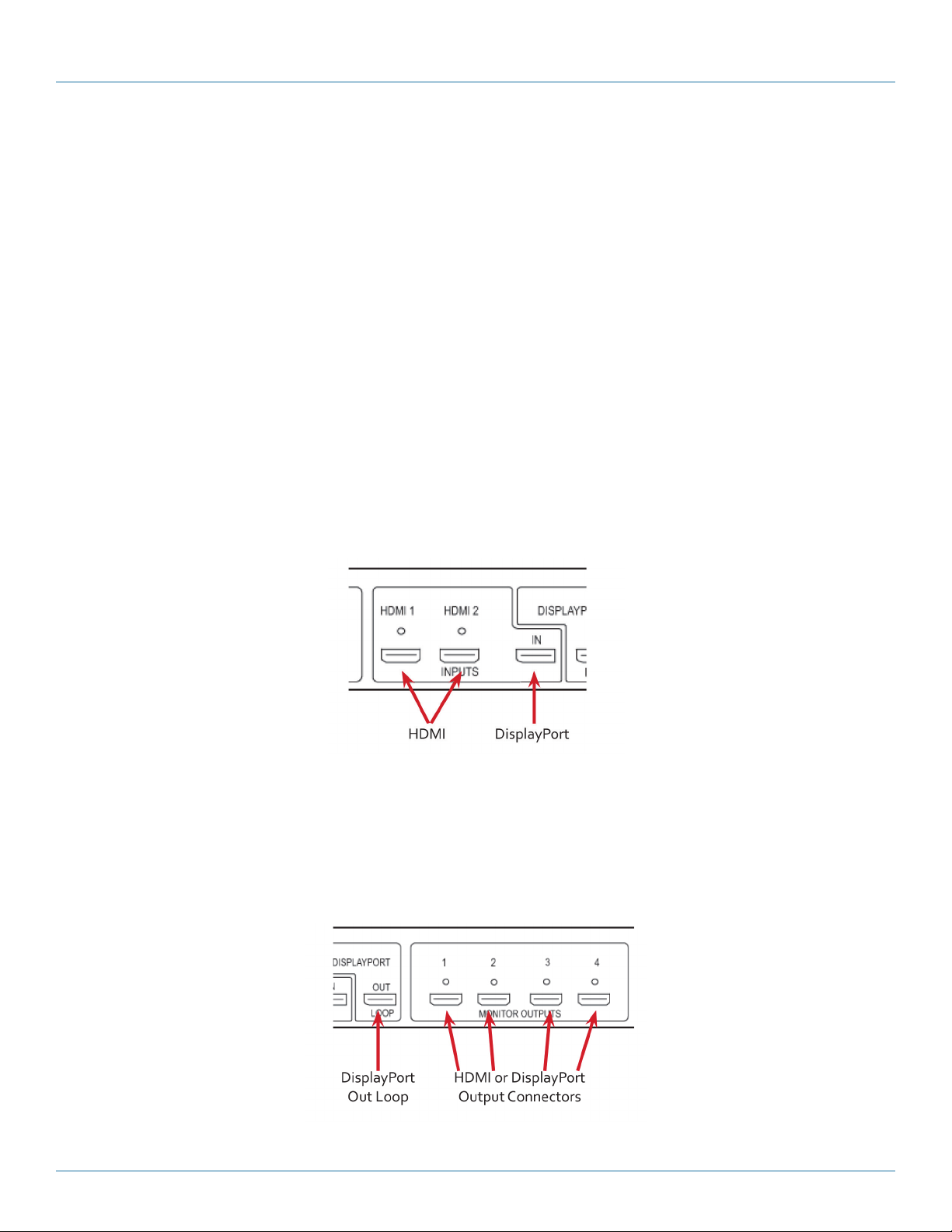
Connect your input source to one of the 3 input connectors on the rear of the VideoPlex4000. You can connect up to 3 input
sources, (2) HDMI and (1) DisplayPort.
Ensure cables are inserted correctly; we recommend using locking cable connectors.
Step 2: Connecting the Outputs
Figure QS-2.
877-877-2269 | blackbox.com
Page 7
Page 8

Quick Start Guide
Connect the monitor cables to the monitor output connectors on the rear of the VideoPlex4000. You can connect up to four
monitors to a single VideoPlex4000 unit. Ensure the cables are inserted correctly; we recommend using locking connectors.
The DisplayPort Out Loop is used when connecting multiple VideoPlex4000 units.
Step 3: Connect a Main Power Cable
Figure QS-3.
When the power is switched on, the VideoPlex4000 will boot and the LEDs on the front panel will flash for up to 15 seconds. If
the LED’s continue to flash, see the troubleshooting section.
Step 4: Connecting to a PC
To successfully configure the VideoPlex4000, first install the VideoPlex Designer application on your PC by running the install program from the DVD.
USB Port
Figure QS-4.
When the VideoPlex4000 has booted, connect it to your PC using the USB cable provided. The VideoPlex4000 unit is a plug-andplay device, VideoPlex Designer will detect it when the layouts are configured.
The VideoPlex4000 can also be configured via a Network, see Step 5.
Step 5: Configure Via a Network
The VideoPlex4000 has dual Ethernet ports to allow users to add the device to their network. Only one VideoPlex4000 in any
chain requires connection to the physical LAN, because Ethernet loopthrough is supported on the second LAN Port, meaning
multiple devices can be connected.
Page 8
Dual Ethernet Ports
Figure QS-5.
877-877-2269 | blackbox.com
Page 9
Quick Start Guide
Connect the VideoPlex4000 to a network using the top LAN connector then open VideoPlex Designer and create your display layout. When you associate the virtual device with a physical device, the list will display all VideoPlex4000’s currently connected to
the network either directly- or daisy-chained.
Click on the virtual device to display its properties. The Device Properties can be changed in the same way as if connecting via
USB. Once any changes have been made, click on Apply Settings to save.
Step 6: VideoPlex Designer
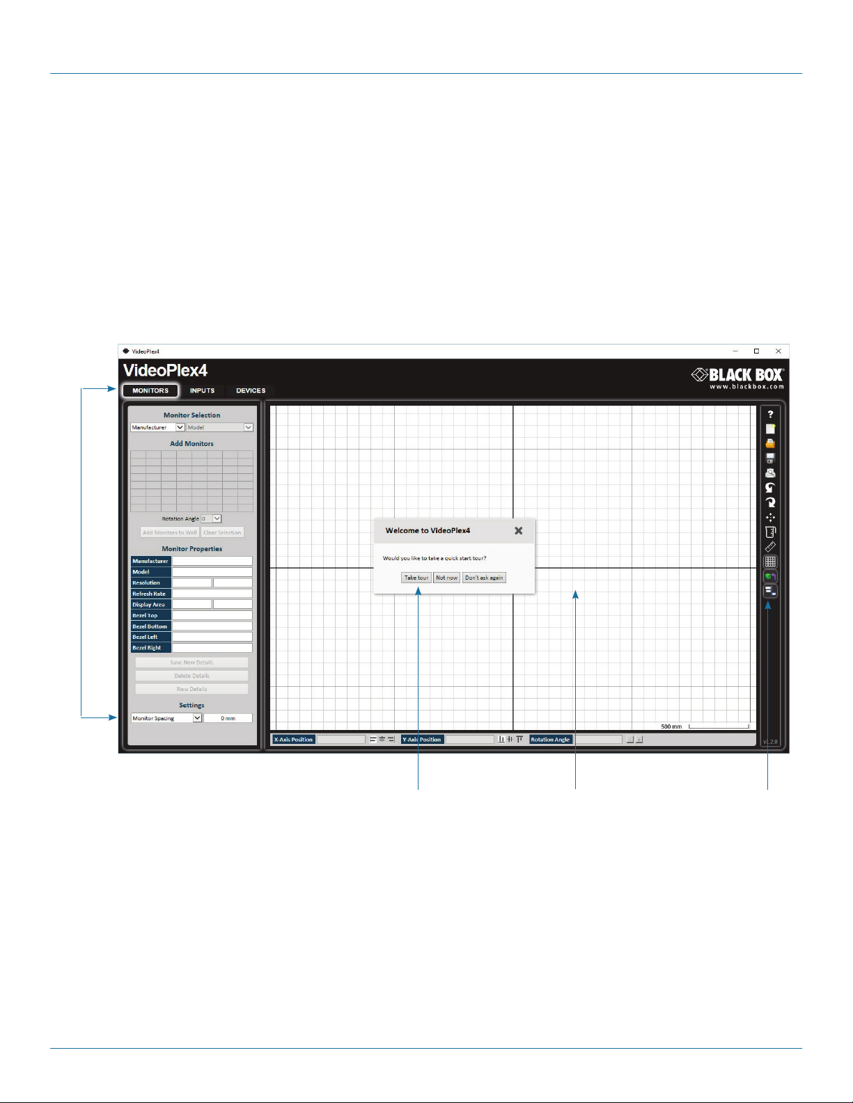
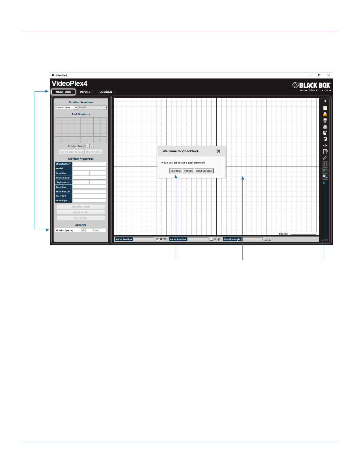
Start —> All Programs —> VideoPlex Designer
When VideoPlex Designer is opened, the following dialog is displayed:
1
2 3 4
Figure QS-6.
1: Operation Modes: Select monitors, inputs, and configure devices.
2: Quick Tour Dialog. When using the program for the first time, we recommend taking the Quick Start Tour.
3: Virtual Canvas
4: Toolbar
877-877-2269 | blackbox.com
Page 9
Page 10

Quick Start Guide
Step 7: Operation
Monitors Inputs Devices
Select the monitor manufacturer
from the drop-down list on the left,
then select the model.
Choose the number of monitors by
clicking and dragging in the Add
Monitors grid.
Select a background to enhance the
Virtual Canvas.
Click Add Monitors to Wall, then
open the Inputs tab.
Set up your input sources to be
displayed on your monitors. Click
on the Create button and select a
sample source for a preview of
what the display wall will look like.
Figure QS-7.
Configure hardware devices by
clicking on Auto-configure
VideoPlex4000. Once you are
satisfied with the configuration,
right-click on the virtual device
in the main window and associate
it with the physical device
connected to your computer
or on your network.
To complete the device configuration,
click on the Apply Settings button.
Page 10
877-877-2269 | blackbox.com
Page 11

Quick Start Guide
Step 8: Multiple Devices
Where more than four outputs are required (the example below shows eight), the Auto Config VideoPlex4000 function will
determine the most logical way to connect all devices. To daisy chain a second VideoPlex4000, use a DisplayPort cable
(not supplied) to connect the DisplayPort Out Loop on the first VideoPlex4000 to the DisplayPort Input on the second
VideoPlex4000.
Step 9: Rackmounting (Optional)
Remove the stud
screws on the side
of your VideoPlex4000
and secure the rack
mounts using the
screws provided.
Figure QS-8.
Figure QS-9.
877-877-2269 | blackbox.com
Pa g e 11
Page 12

Quick Start Guide
Step 10: IP Control Panel
The VideoPlex4000 has a control panel that can be accessed via an IP connection; simply type in the IP address of the
VideoPlex4000 into an Internet browser and a control panel for that particular VideoPlex4000 is displayed. The control panel
allows you to change properties and settings, manually define cropping regions, upload your particular logo, or open the VideoPlex
Designer application.
Video Plex40 00 Control Pa nel
Figure QS-10.
Step 11: Troubleshooting
Display Screens Turn Red
If all the display screens turn red, this indicates that there is an issue with HDCP compliance. Check that both the input source and
the monitors are HDCP compliant.
Front Panel LED Lights
On start-up all three lights will flash, after a few seconds the flashing should stop and the power light stays on permanently.
If the light continues to flash, the VideoPlex4000 requires upgrading. Contact Technical Support for details on how to upgrade
your VideoPlex4000.
Page 12
877-877-2269 | blackbox.com
Page 13

Chapter 1: Specifications
1. Specifications
Approvals FCC, TUV, CE, UL®, RoHS, WEEE
Control Interfaces Dual 100BASE-T Ethernet ports with built-in managed switch. USB 2.0 Type B connector (full speed operation)
Firmware Support Updates supported via USB and Ethernet connection
Genlock Input Analog black-burst on dedicated BNC connector. Any video input (HDMI1, HDMI2, DisplayPort)
Heat Dissipation 3. 41 BT U / hr
Input Resolution HDMI 1.4: 3840 x 2160 @ 30 Hz or equivalent up to 297 Mps;
DisplayPort 1.2: 3840 x 2160 @ 60 Hz or equivalent up to 616 Mps)
Input Surface 8 K x 8 K maximum
Leads Supported HDMI and DisplayPort input, HDMI output
Operating System
Support
Output Resolution HDMI: 1080p /60 or equivalent up to 165 Mps;
USB Support USB 2.0, full-speed (12 Mbps) operation;
User Controls (1) Power switch
Interface (2) HDMI capture, (1) Single-link DisplayPort;
Connectors Input:
Indicators (3) LEDs:
Environmental Temperature Tolerance:
Power Input Voltage/Volts: 100–240 VAC, 50/60 Hz internal power supply;
Dimensions 1.75"H x 12.4"W x 6.7"D (4.4 x 31.6 x 17.2 cm)
Weight 4.1 lb. (1.86 kg)
All known operating systems;
All known hardware that supports/follows the HDMI spec
Loop-through: DisplayPort1.2 (locked to selected video input resolution)
Firmware support: Updates supported via USB
(4) HDMI output, (1) DisplayPort loopthrough
(2) HDMI female,
(1) DisplayPort female;
Output:
(1) DisplayPort female,
(4) HDMI female;
Power: (1) IEC-C14;
(1) USB Type B female;
(1) Sync port;
(2) RJ-45 Ethernet
(1) Power,
(1) Input,
(1) Status
Operating: 32 to 95° F (0 to 35° C);
Storage: -4 to +158° F (-20 to +70° C);
Humidity:
Operating: 90%, noncondensing;
Maximum Altitude: 6400 ft. (2000 m)
Input Current/Watts: 30 W;
Power Consumption/ Watts: 30 W
877-877-2269 | blackbox.com
Page 13
Page 14

Chapter 2: Overview
2. Overview
2.1 Introduction
The VideoPlex4000 is a standalone display wall controller that supports two HDMI 1.4 inputs for 4K @ 30 Hz and one DisplayPort
1.2 input for 4K @ 60 Hz. The intuitive user interface allows users to determine which input is used.
DisplayPort 1.2 Loopthrough allows the DP video to be viewed on a local monitor as well as on the wall.
Outputs support 1080p to up to 4 HDMI displays.
2.2 Configuration Examples
On the next few pages are just a few examples of what can be achieved with the VideoPlex4000. The examples are not definitive
and users are encouraged to experiment with different display configurations.
Page 14
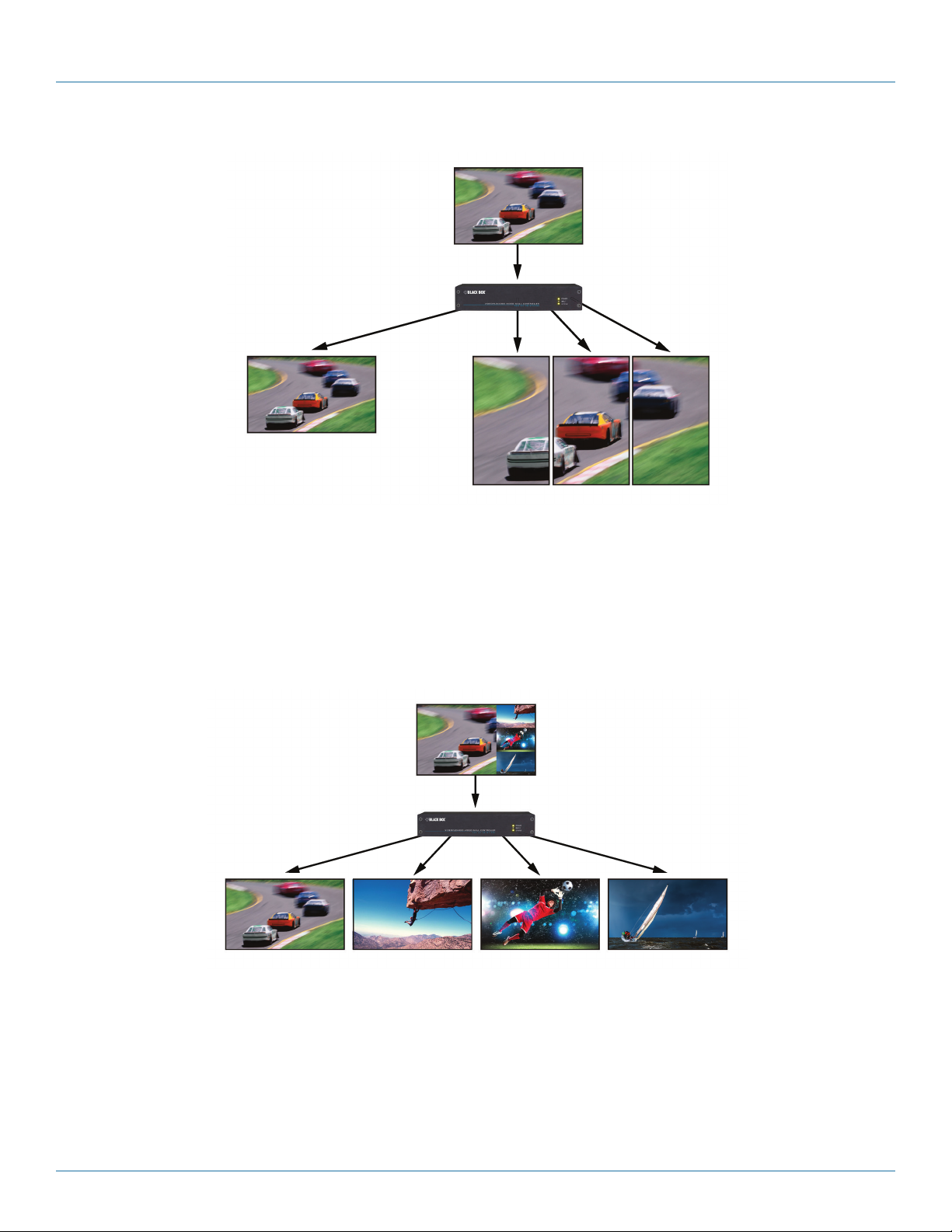
Figure 2-1. Duplicate the input signal x 4 and display each duplicate on separate screens.
877-877-2269 | blackbox.com
Page 15

Chapter 2: Overview
Figure 2-2. Divide the input signal into quadrants and display each quarter on separate displays with optional frame rate
conversion (in this case 30 to 60 Hz). You can adjust crop regions to compensate for monitor bezel.
877-877-2269 | blackbox.com
Page 15
Page 16
Chapter 2: Overview
Figure 2-3. Duplicate the input signal x2 and display one output on a single landscape display and divide the second output into
thirds, rotate to portrait, upscale, and split between three displays.
Page 16
Figure 2-4. Crop input signal, upscale specific areas, and display on four separate screens.
877-877-2269 | blackbox.com
Page 17

Chapter 2: Overview
Figure 2-5. Crop the input signal into VideoPlex4000 and display x2 quarters landscape and x2 quarters portrait.
877-877-2269 | blackbox.com
Page 17
Page 18

Chapter 2: Overview
Figure 2-6. Crop the input signal, rotate through 90º, 180º, or 270º; display in landscape and portrait. Arbitrary crop regions can
allow the monitors to be artistically arranged, but maintain an undistorted image.
2.3 Features
Each output monitor can take its input from any region of the input image as all of the required cropping, scaling, rotation and
frame-rate conversion is handled by the Black Box VideoPlex4000 hardware. These regions can overlap to allow any output to
replicate another or can be configured to support any creative splice of the source material. This allows the support of many
non-rectangular screen arrangements with uneven gaps, and any mix of monitor orientations.
• Infinite creative configurations.
• Up to Ultra HD input, four HD 1080p outputs.
• Rotates, crops, scales, mirrors and bezel-corrects.
• Dual HDMI 1.4 and single DisplayPort 1.2 inputs for 4k 60 Hz source capture.
• HDCP support on all inputs and outputs.
• Standalone operation: Non-volatile configuration can adapt to changes in inputs by automatically adjusting all scale factors.
• Power-down configuration-save facility, power up instantly with no re-setup required.
2.4 What’s Included
Your package should contain the following items. If anything is missing or damaged, contact Black Box Technical Support at
877-877-2269 or info@blackbox.com.
• VideoPlex4000 unit
• (1) rackmount kit
• (1) USB 2.0 cable Type A to Type B
• (1) DVD containing the software application and the VideoPlex 4000 user guide
• (1) Quick Start Guide
Page 18
877-877-2269 | blackbox.com
Page 19
Chapter 2: Overview
• (1) IEC-320 C13 to Nema 5-15 power cable
• (6) rackmount screws
• (6) HDMI cable locks
• (6) tie wraps
NOTE: The VideoPlex4000 is not supplied with input and output cables therefore please ensure you have the relevant cables
on hand to complete your project.
NOTE: We recommend that you do not discard the packing box until you are completely satisfied with the VideoPlex4000
and it is fully installed and working correctly. We also recommend that you note the serial number of the controller
in a prominent place before you connect it to the computer. You will be asked to provide this serial number if you need
to contact our Technical Support department. The serial number is displayed on the VideoPlex4000 and the box label.
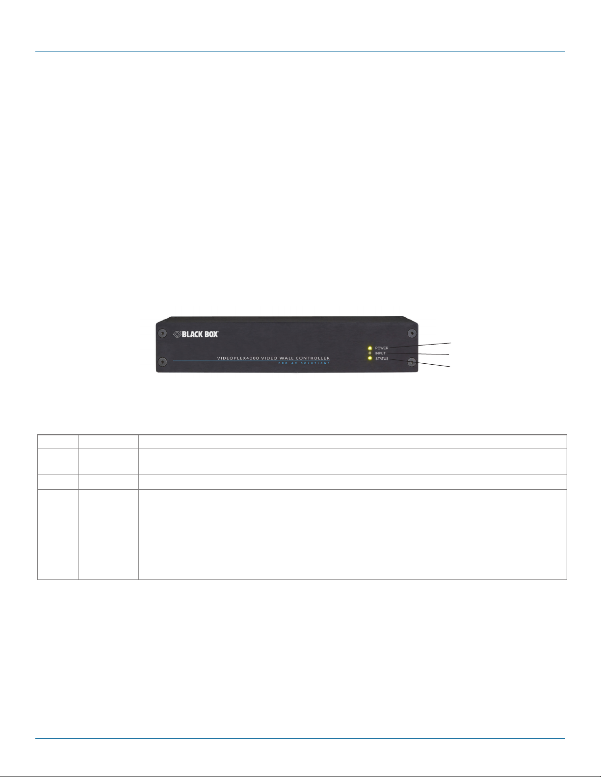
2.5 Hardware Description
2.5.1 Front Panel
1
2
3
Figure 2-7. Front panel.
Table 2-1. Front-panel components.
Number Indicator Description
1 (1) Power LED Lights when the VideoPlex4000 is connected to the power supply. The LEDs can flash for up to 15 seconds
when the VideoPlex4000 is switched on.
2 (1) Input LED Lights when a valid source is connected.
3 (1) Status LED Lights steady on when the VideoPlex4000 is operating normally.
Flashing when the unit is operating over the normal operating temperature. Make sure that the input fan vent is
not blocked.
Off when the settings configured in the VideoPlex4000 application no longer match the input. This is normally
the result of a change of input. The VideoPlex4000 will compensate for the settings and reconfigure itself to display as near to the settings as possible. The output will still be displayed, but not necessarily as expected.
NOTE: When the VideoPlex4000 is connected to a PC by a USB cable and the VideoPlex4000 control application is active,
all three lights flash to identify which unit is being controlled.
877-877-2269 | blackbox.com
Page 19
Page 20
Chapter 2: Overview
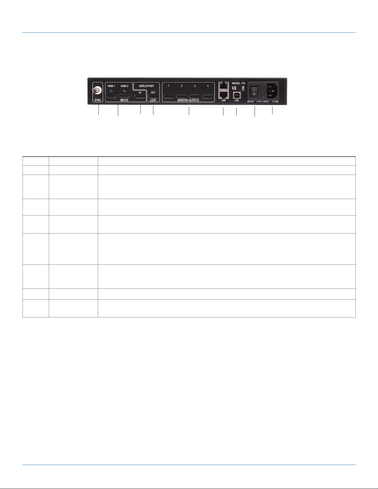
2.5.2 Back Panel
1 2 3 4 5 6 7 8 9
Figure 2-8. Back panel.
Table 2-2. Back-panel components.
Number Indicator Description
1 Sync Socket The Sync socket accepts tri-level or black-burst syncs for genlocking the VideoPlex4000 to external devices.
2, 3 Input Sockets The VideoPlex4000 has three input connectors, one DisplayPort and two HDMI. All three inputs can be
connected to sources playing concurrently, however only one of the inputs can be displayed at any one time.
Switching between inputs is achieved using the VideoPlex4000 software application.
4 DisplayPort Out
Loop
5 HDMI Monitor
Outputs
Used to connect multiple VideoPlex4000 systems, enabling larger display walls.
The HDMI monitor output connectors are used to connect the VideoPlex4000 to the display monitors.
6 (2) LAN ports Dual 100BASE-T Ethernet ports with built-in managed switch The LAN connector is used to connect the
VideoPlex4000 to a network for configuration and control; it can also be used to connect multiple
VideoPlex4000 units in a daisy-chain architecture using Ethernet cables. Ethernet loop through is supported.
The LAN connector can also be used to connect the VideoPlex4000 to a PC for configuration.
7 USB Socket The USB socket is used to connect the VideoPlex4000 to a PC via a USB connection using the supplied USB
Type A to Type B cable. Configuration of the VideoPlex4000 is programmable via an application utility,
allowing easy control of cropping, scaling, rotation, and gaps.
8 ON/OFF Switch Turns the unit ON or OFF.
9 Power The Power socket is where the supplied power source connects to the VideoPlex4000. The power LED on
the front of the VideoPlex4000 illuminates when a power supply is connected.
Page 20
877-877-2269 | blackbox.com
Page 21
Chapter 2: Overview
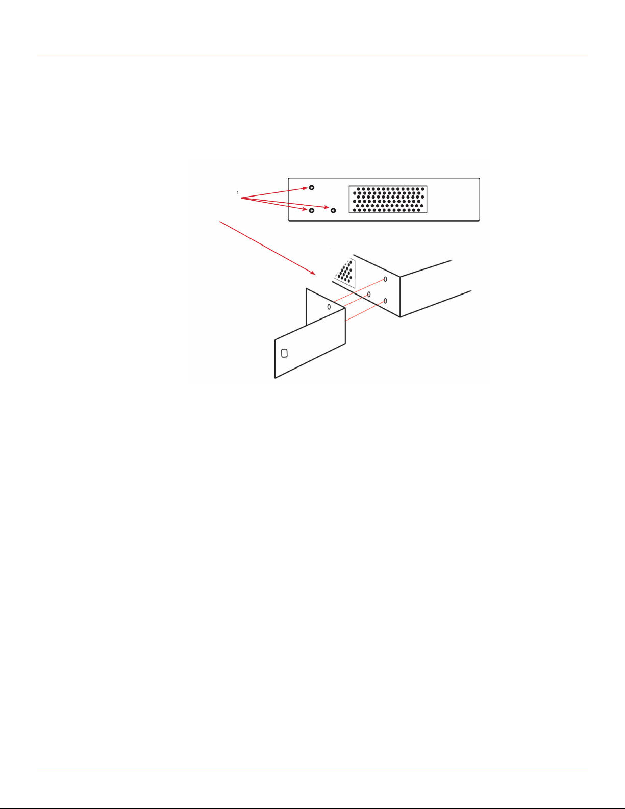
2.6 Rackmounting the VideoPlex4000
The VideoPlex4000 is supplied with attachments to enable you to mount the VideoPlex4000 in a rack. Remove the 3 mounting
screws on each side of the VideoPlex4000 using a cross head screwdriver and attach the rack mounts as shown in the illustration
below.
Remove the stud
screws on the side
of your VideoPlex4000
and secure the rack
mounts using the
screws provided.
Figure 2-9. Rackmounting the VideoPlex4000.
877-877-2269 | blackbox.com
Page 21
Page 22

Chapter 3: Software
3. Software
This chapter will cover:
• Introduction to VideoPlex Designer.
• Installing the VideoPlex Designer application.
• Running the VideoPlex Designer application.
• A summary of VideoPlex Designer features.'
3.1 VideoPlex Designer
Multi-monitor display wall installations can be challenging to design, build, configure, and implement. Highly creative display
projects often require multiple monitors arranged in unconventional formations with a myriad of bezel sizes, gaps, and monitor
positions. Project designers, installers, and integrators require simple yet effective video wall creation tools to manage the project
from start to finish.
The software includes a community-driven database of monitors from popular manufacturers that continues to grow as users add
their own monitor specifications and submit them back to Black Box for inclusion in the next database update.
3.2 VideoPlex Designer Features
VideoPlex Designer is the perfect solution to creating and managing your display wall project from start to finish, giving you total
creative control reliably and efficiently.
Black Box’s monitor database is regularly updated with new manufacturers and models. Users can add and submit their own
monitor information and once validated, will be added to the master database.
• Monitors can be arranged landscape and portrait with gaps.
• Add content into your project and place it across the virtual canvas filling the monitors with content.
• Automatically configure the VideoPlex4000, assigning each output to a monitor.
• Print out design schematics to aid physical monitor installation.
• Includes language support for German. Spanish, French, Japanese, Polish, Portuguese, Russian and Simplified Chinese.
• Comprehensive help files guide you through the application.
3.3 Installing the VideoPlex Designer
3.3.1 Software DVD
The Black Box Software DVD supplied with your VideoPlex4000 display controller contains the VideoPlex Designer application.
We recommend that users regularly visit the Black Box website for information on new software releases.
Insert the software DVD into a DVD drive and the installation wizard should begin automatically. If the installation wizard does
not start, browse the DVD, locate and double-click SetUp.exe and the following dialog is displayed.
Page 22
877-877-2269 | blackbox.com
Page 23
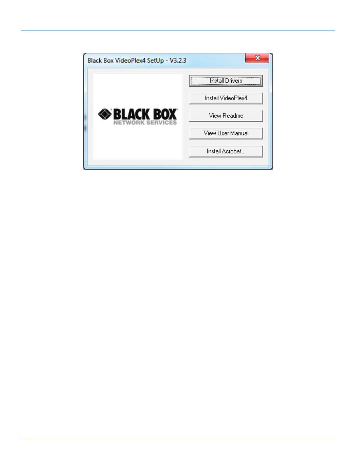
Figure 3-1. VideoPlex Designer software dialog box.
Chapter 3: Software
3.3.2 Install the VideoPlex Designer Software
Click on Install VideoPlex Designer to initiate the installation wizard. VideoPlex Designer is a multi-lingual application and you are
offered a selection of languages when the install process begins. Select the required language and the install wizard will continue
installing the software.
3.3.3 View Readme
Click on View Readme to open an HTML document containing the latest information and bug fixes for the application. The
VideoPlex Designer application can be installed from the Readme.
3.3.4 View User Guide
Click to open the user guide in PDF format.
3.3.5 Install Acrobat
Install Acrobat is provided to enable you to read the PDF User Guide.
3.4 Running the VideoPlex Designer Application
Once the software has been installed you can open the application:
Start —> All Programs —> VideoPlex Designer
877-877-2269 | blackbox.com
Page 23
Page 24
Chapter 3: Software
3.4.1 VideoPlex Designer Interface
When VideoPlex Designer is opened, the following dialog is displayed:
1
2 3 4
Figure 3-2. VideoPlex Designer interface screen.
1: Operation Modes: Select monitors, inputs, and configure devices.
2: Quick Tour Dialog. When using the program for the first time, we recommend taking the Quick Start Tour.
3: Virtual Canvas
4: Toolbar
3.4.2 Operation Modes
The application has three separate operation modes: Monitor, Inputs, and Devices:
Monitors
VideoPlex Designer includes a database containing a selection of the more commonly used monitor manufacturers and model.
Use the manufacturer and models dropdown list to select a specific monitor. When selected, the monitor properties are automatically populated with the monitor specification.
To add monitors, simply click or click and drag the cells inside the 8x8 grid. Once the monitors have been arranged on the virtual
canvas and you are happy with the wall design, click on Add Monitors to Wall.
Add a background image to enhance the Virtual Canvas.
Page 24
877-877-2269 | blackbox.com
Page 25

Chapter 3: Software
Inputs
The inputs section of the application toolbar enables you to select a given input and allocate regions of the input to each monitor
on the display wall.
A collection of sample sources are available via a dropdown menu; this contains a list of images and videos contained within the
application’s and user’s media folder.
Devices
The devices section of the application toolbar brings together the input, hardware devices, and the monitors, thereby completing
the design of your display wall. This is done by allocating the input to available devices and the outputs from the devices
to specific monitors on the display wall.
VideoPlex Designer has an automatic configuration feature (Auto-config) that, when clicked, automatically adds the required number
of devices and configures all the links from the input to the monitors via your VideoPlex4000’s in the most logical configuration.
The virtual device can be associated with an actual device by right clicking on it and selecting Associate Device. Click in the device
to display the device properties, these properties can be changed if required, for example the Friendly Name (recommended).
3.4.3 Quick Tour
When opening the application for the first time a quick tour dialog is presented. We recommend that you take a few minutes to
complete the tour. The quick tour dialog can be turned off so it will not be displayed in the future.
3.4.4 Virtual Canvas
The Virtual Canvas displays a representation of the monitors selected and their orientation, offering a view of the completed wall
design. In Device mode, the Virtual Canvas illustrates how the input source, VideoPlex4000(s) and monitors are configured.
3.4.5 Toolbar
The toolbar offers a group of tools that assist in creating, opening, and saving layouts, you can also display actual video wall
measurements in metric or English units.
3.4.6 Help Files
The VideoPlex Designer application has a an built-in help file system which can be accessed by clicking on the ? at the top
of the toolbar.
877-877-2269 | blackbox.com
Page 25
Page 26

Chapter 4: Cabling
4. Cabling
This chapter will cover:
• Connecting a house sync cable.
• Attaching HDMI cable lock.
• Connecting input sources.
• Connecting a loop-through output cable.
• Connecting the outputs to monitors.
• Cable lengths.
4.1 Connecting a Sync Cable
The Sync BNC connector supports tri-level and black-burst video signals that are used to genlock the 4 monitors. For multiple
VideoPlex4000’s, a distribution unit is required (not supplied).
4.2 Attaching an HDMI Cable Lock
The VideoPlex4000 is supplied with HDMI cable locks that you should use on non-lockable HDMI cables to ensure they remain
firmly attached to the VideoPlex4000.
Thread the cable tie through the
holes in the side of the cable lock.
Sit the cable lock on the top of the
HDMI cable connector ensuring the
cable lock is flush with the front of the
shroud on the HDMI connector.
Figure 4-1. Attaching an HDMI cable lock.
Pull the cable tie tightly and
ensure it fits firmly on the
HDMI connector shroud.
4.3 Connecting Input Sources
The Black Box VideoPlex4000 has three dedicated input connectors: two HDMI and one DisplayPort. We strongly recommend
that you use locking cables to prevent the input source cables from becoming detached from the VideoPlex4000. HDMI cable
locks are provided and should be attached to your cables as shown above.
Figure 4-2. Connecting HDMI input cable.
Page 26
877-877-2269 | blackbox.com
Page 27

Chapter 4: Cabling
4.4 Connecting the Out Loop
The Out Loop connector is used to connect two or more VideoPlex4000’s when the requirement is to create large video display
walls with more than 4 monitors.
Using a DisplayPort cable (not supplied) connect the Out Loop from the first VideoPlex4000 to the DisplayPort Input on the
second VideoPlex4000 and so on until all the required units are connected. The input signal will be gen-locked through all the
connected VideoPlex4000s in the chain. The output has been oprtrimized for connection to another VideoPlex4000 and may not
link to a standard DisplayPort monitor.
4.5 Connecting Outputs to Monitors
Each VideoPlex4000 display controller can support up to four monitors on a display wall, the output connectors will be HDMI.
Once again, we highly recommend that you use locking cables.
Each output can display any region of the input image; all the required cropping, scaling, and rotations is calculated within the
VideoPlex4000 hardware.
Figure 4-3. Connecting HDMI output cable.
4.6 Cable Lengths
Workable cable lengths depend on the quality of the cables used to set up your VideoPlex4000. Black Box recommends using
certified cables when installing your VideoPlex4000.
Table 4-1. Cable lengths.
Ca ble Type Bit Rate Maximum Length
HDMI (output) N/A 32 ft. (10 m)
DisplayPort (output) Reduced Bit Rate (RBR) 64 ft. (20 m)
DisplayPort (output) High Bit Rate (HBR) 32 ft. (10 m)
DisplayPort (loopthrough) Reduced Bit Rate (RBR) 64 ft. (20 m)
DisplayPort (loopthrough) High Bit Rate (HBR) 32 ft. (10 m)
DisplayPort (loopthrough) High Bit Rate 2 (HBR2) 6.4 ft. (2 m)
Ethernet Cable (Network/Setup) N/A 328 ft. (100 m)
USB (Setup) N/A 9.6 ft. (3 m)
NOTE: The VideoPlex Designer software has a Maximum Link Rate selector which enables you to manually select the link rate
of the DisplayPort input to suit your own requirements. The default rate of HBR2 allows operation up to the full 4k/60
capability of the DisplayPort input, but if the actual input signal is only HD then the maximum link rate can be changed
to HBR or RBR to enable the use of longer cables.
877-877-2269 | blackbox.com
Page 27
Page 28

Chapter 5: Operation
5. Operation
This chapter will cover:
• Setting up the VideoPlex4000
• Switching on the VideoPlex4000
• Configuring the VideoPlex4000 using a USB connection
• Configuring the VideoPlex4000 over a Network
5.1 Setting up the VideoPlex4000
5.1.1 Connecting an Input
First, make sure you have all the relevant input and output cables you need for your project:
• Begin by connecting your input source to one of the three input connectors on the rear of the VideoPlex4000. You can connect
up to three input sources, two HDMI and one DisplayPort. If using more than one VideoPlex4000, the DisplayPort Input
connector will act as the loop through input on the additional devices. Make sure the input cables are inserted correctly;
we recommend that you use locking cable connectors.
Figure 5-1. Connecting inputs.
5.1.2 Connecting Outputs
Up to four HDMI cables and one DisplayPort cable (if using the DP loopthrough) are required (not supplied). The VideoPlex4000
has five output connectors: four monitor outputs and one DisplayPort loopthrough.
• Connect the monitor cables to the monitor output connectors on the rear of the VideoPlex4000, you can connect up to four
monitors to a single VideoPlex4000 unit. Make sure the cables are inserted correctly; we recommend using locking connectors.
• The DisplayPort Out Loop is used when connecting multiple VideoPlex4000 units. See Chapter 5 for cabling requirements.
Figure 5-2. Connecting outputs.
Page 28
877-877-2269 | blackbox.com
Page 29

Chapter 5: Operation
5.2 Switching On the VideoPlex4000
The VideoPlex4000 has a built-in power unit that is controlled using the power switch on the rear panel. Connect the power
cable supplied with your VideoPlex4000 and plug it into a power supply. Switch on the power on the rear of the VideoPlex4000
as shown in the following illustration.
Power switch
Figure 5-3. Power switch on the unit.
NOTE: When the power is switched on, the VideoPlex4000 will boot and the LEDs on the front panel will flash as described
in Chapter 1.
NOTE: It can take up to 15 seconds for the VideoPlex4000 to fully boot.
5.3 Configuring the VideoPlex4000 via USB
When the VideoPlex4000 has booted, connect it to the computer that has the VideoPlex Designer application installed using the
USB cable provided.
The VideoPlex4000 is a plug-and-play device, so it relies on the device drivers in the Windows operating system.
To enable the operating system to “attach” to the VideoPlex4000, you must ensure the Device Installation Settings
are set to automatic:
Go to Control Panel \ Devices and Printers, then right-click on your computer icon and select “Device Installation
Settings” form the menu. In the Device Installation Settings, select “Yes, do this automatically (recommended)” and
click on Save Changes.
USB Port
Figure 5-4. USB port.
Open the VideoPlex Designer application and begin to design your video wall layout using the Monitors tab as described in
Chapter 3.
With the monitors selected and the layout completed, select the Input tab. Allocate the input to the VideoPlex4000 by clicking
on Create, then selecting the required input from the drop down menu.
Once the input has been selected, navigate to the Devices tab; this is where the VideoPlex4000 is configured.
877-877-2269 | blackbox.com
Page 29
Page 30

Chapter 5: Operation
The Devices window is where the input, devices, and monitors are linked to complete the design of the video wall; this is done by
allocating inputs to devices and the outputs from the devices to specific monitors on the video wall.
For ease of use, the Auto-config VideoPlex4000 function will, when clicked, automatically add devices and configure all the links
from the inputs to the monitors via the VideoPlex4000 in the most logical configuration.
Click on the Auto-config VideoPlex4000 button and a visual representation of the configured VideoPlex4000 will appear in the
main window, for example:
Figure 5-5. Example #1 application.
The illustration shows the input source connected to Input 1 (HDMI1) on the VideoPlex4000 and each monitor connected
to the respective output connector.
When more than four outputs are required, (the example below shows eight), the Auto Config VideoPlex4000 function will
determine the most logical way to connect all devices. The blue output connector on the first VideoPlex4000 represents the
DisplayPort Out Loop connector, which is used to daisychain additional VideoPlex4000’s if more outputs are required. To daisychain a second VideoPlex4000, use a DisplayPort cable (not supplied) to connect the DisplayPort Out Loop on the first
VideoPlex4000 to the DisplayPort Input on the second VideoPlex4000.
Page 30
Figure 5-6. Example #2 application.
877-877-2269 | blackbox.com
Page 31

Chapter 5: Operation
To associate the virtual VideoPlex4000 in the main window with an actual physical device, highlight the device by right-clicking,
then select Associate Device from the displayed menu; a list of available VideoPlex4000s is displayed.
Click on the virtual device to display its properties; the Device Properties can be changed if required, for example, you may wish to
allocate a different Friendly Name that can be useful when connecting to multiple devices. Once changes have been made, click
on Apply Settings to save.
If an input source is connected to the VideoPlex4000 but the actual signal fails, the VideoPlex4000 will try to connect to a valid
signal by scanning the input connectors in the following order:
1 - DisplayPort
2 - HDMI 1
3 - HDMI 2
If no signal is detected on either of the three input connectors, the VideoPlex4000 will display a pre-configured Black Box logo.
To upload your preferred logo (max 4K), click on the Upload Logo button in the Devices Tab and browse to upload your logo.
NOTE: It can take up to five minutes to complete the upload.
NOTE: Full instructions on how to configure your VideoPlex4000 are available in the VideoPlex Designer application help file.
5.4 Configuring the VideoPlex4000 via a Network
The VideoPlex4000 has dual Ethernet ports to allow users to add the device to their network. Only one VideoPlex4000 in any
chain requires connection to the physical LAN, because Ethernet loopthrough is supported on the second LAN Port, meaning
multiple devices can be connected.
Dual Ethernet Ports
Figure 5-7. Dual Ehernet ports.
Connect the VideoPlex4000 to a network using the top LAN connector, then open VideoPlex Designer and create your display
layout as described in Section 5.3.
At the point where you associate the virtual device with a physical device, the list will display all VideoPlex4000s currently
connected to the network either directly or daisychained.
Click on the virtual device to display its properties; the Device Properties can be changed in the same way as if connecting via
USB. Once any changes have been made, click on Apply Settings to save.
5.5 Network Settings
The Network Settings become active once you have successfully connected to an VideoPlex4000 either by USB or Ethernet.
The VideoPlex4000 allows you to switch between Dynamic (DHCP) and Static IPs. Out of the box, the VideoPlex4000
is configured to accept DHCP.
When DHCP is selected, the network will assign the VideoPlex4000 with an IP address; this IP address can change depending
on how the network allocates IP addresses.
877-877-2269 | blackbox.com
Page 31
Page 32

Chapter 5: Operation
If the VideoPlex4000 is assigned a Static IP address, it will keep that address until it is changed by the user.
The IP Address, Subnet Mask, and Gateway fields are not available to edit if DHCP is selected and the display settings are assigned
via a DHCP server.
In Static mode, the IP Address, Subnet Mask, and Gateway can be manually configured.
Page 32
877-877-2269 | blackbox.com
Page 33

Chapter 6: Troubleshooting
6. Troubleshooting
6.1 Display Screens Turn Red
If all the display screens turn red, this indicates that there is an issue with HDCP compliance. Check both the input source
and the monitors are HDCP compliant. If neither are HDCP compliant, you can stop the VideoPlex4000 from automatically
negotiating an HDCP link by disabling HDCP in the VideoPlex Designer application.
In the Devices tab, select the input to display the Advanced Timing Properties and uncheck the HDCP Enabled box.
6.2 Network Timing Out
The network connection fails and the VideoPlex4000 can’t be seen in devices. This indicates that an IP address needs to be set.
6.3 Front Panel LED Lights
On start-up, all three lights will flash; after a few seconds the flashing should stop and the power light stays on permanently.
If the light continues to flash, this indicates that the VideoPlex4000 requires upgrading.
To upgrade, connect the VideoPlex4000 via the USB or Network interface to a PC and open the VideoPlex Designer application.
Create a monitor layout, allocate an input, and auto-configure the VideoPlex4000. When the visual representation of the
VideoPlex4000 appears in the Device window, a blue information icon will be displayed.
Click on the information icon for details of available upgrades.
6.4 Intermittent or Loss of Input Signal
If you lose your input signal or if the signal is intermittent, there might be a problem with the link rate between the source and
the VideoPlex4000.
Check that all cables are fitted correctly.
When using DisplayPort cables, ensure that the bitrate and cable length are compatible using the table shown in Chapter 4,
or try selecting a lower maximum link rate in the VideoPlex Designer application.
6.5 Technical Support
Contact Black Box Technical Support 24/7 at 877-877-2269 or info@blackbox.com.
Supply as much information about your system as possible. To enable a swift response, our support team will need to know the
following details:
• Specification of the PC - including processor speed.
• Operating system.
• Application Software.
• Black Box Hardware/Software.
• Details of the input source.
• The exact nature of the problem—please be as specific as possible.
• Please quote version and revision numbers of hardware and software wherever possible.
877-877-2269 | blackbox.com
Page 33
Page 34

Chapter 7: Maintenance
7. Maintenance
Your VideoPlex4000 requires little maintenance, but be careful to keep all ventilation holes clear to allow an unrestricted flow
of air through the unit.
NOTE: Failure to keep ventilation holes clear could result in damage to your VideoPlex4000 and invalidate the warranty.
Page 34
877-877-2269 | blackbox.com
Page 35

NOTES
877-877-2269 | blackbox.com
Page 35
Page 36

Black Box Tech Support: FREE! Live. 24/7.
Tech support the
way it should be.
Great tech support is just 60 seconds away at 877-877-2269 or blackbox.com.
About Black Box
Black Box provides an extensive range of networking and infrastructure products. You’ll find everything from cabinets and racks
and power and surge protection products to media converters and Ethernet switches all supported by free, live 24/7 Tech support
available in 60 seconds or less.
© Copyright 2016. Black Box Corporation. All rights reserved. Black Box® and the Double Diamond logo are registered trademarks of BB Technologies, Inc.
Any third-party trademarks appearing in this manual are acknowledged to be the property of their respective owners.
VSC-VPLEX4000, version 1
877-877-2269 | blackbox.com
 Loading...