

Page 1
VoIP Analog Gateway
Gaithersburg, Maryland
M- ATA
Micro-Analog
Telephone Adapter
P
H
O
N
E
L
A
N
S
Y
S
T
E
M
P
O
W
E
R
DECEMBER 2007
VOE101
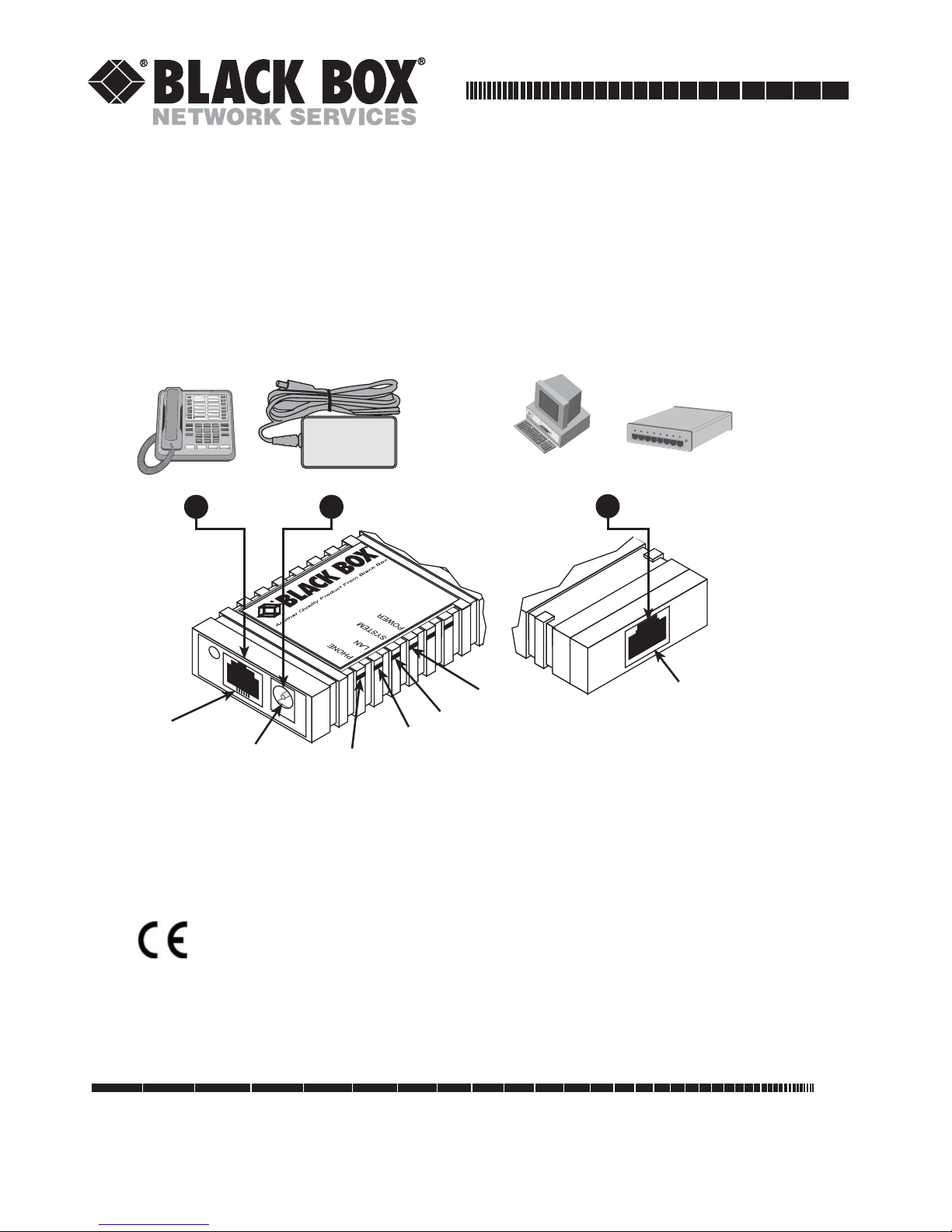
Phone
Front
view
Phone jack
Power adapter
2 4
VOE101
Power jack
Phone LED
Figure 1.
PC or
LAN
Power LED
System LED
LAN LED
VOE101 installation diagram
--or--
3
LAN
Hub/Switch
Rear
view
LAN port
Important
This is a Class B device and is intended for use in a light industrial or residential environment. It is
not intended nor approved for use in an industrial environment.
CUSTOMER
INFORMATION
SUPPORT
Order toll-free in the U.S. 24 hours, 7 A.M. Monday to midnight Friday: 877-877-BBOX
FREE technical support, 24 hours a day, 7 days a week: Call 724-746-5500 or fax 724-746-0746
Mail order: Black Box Corporation, 1000 Park Drive, Lawrence, PA 15055-1018
Web site: www.blackbox.com • E-mail: info@blackbox.com
Page 2

VOIP ANALOG GATEWAY
• This device contains no user serviceable parts. The
equipment shall be returned to Black Box for repairs, or
repaired by qualified service personnel.
• The external power adapter should be a listed Limited
Power Source. Ensure that the power cable used meets
all applicable standards for the country in which it is to
be installed, and that it is connected to a wall outlet
which has earth ground. The mains outlet that is utilized to power the device shall be within 10 feet (3
WARNING
meters) of the device, shall be easily accessible, and
protected by a circuit breaker.
• Do not work on the system or connect or disconnect
cables during periods of lightning activity.
2
Page 3

VOIP ANALOG GATEWAY
123
4
567
1. Quick Start
The interconnecting cables shall be acceptable for
external use and shall be routed for the proper application with respect to voltage, current, anticipated temperature, flammability, and mechanical servicability.
CAUTION
The unit should be installed in a dry environment with at least 2 inches (5 cm) of
clearance at the sides and front of the unit to allow air circulation for cooling.
Plug in the telephone (see
figure 1
on page 1).
Plug in the PC or LAN, or a LAN hub/switch.
Plug the power adapter into the power jack on the VOE101 (see
figure 1
on
page 1). Connect the other end of the power cord to an appropriate AC power
outlet.
Wait 30 seconds after powering the VOE101 on, then verify that the green
Power
LED is lit (see
figure 1
on page 1).
By default, the VOE101 will automatically request IP network settings from the
LAN using DHCP. To determine the IP address of the device, lift the handset off
the attached analog phone and dial
Dial
1 0 0 #
, listen to and record the IP address of the device. (To manually set
* * * *
.
the IP address, see appendix “Existing voice prompt configuration” on page 5
for details).
Use a web browser to connect to the VOE101. The URL will be http://<ip
address>. For example, if the VOE101 IP address was
would be
The default password is “
http://10.10.10.2
.
root
”.
10.10.10.2
, the URL
Follow the directions of your voice service prodifer to set
up voice services.
CAUTION
3
Page 4

VOIP ANALOG GATEWAY
A. Compliance Information
A.1 Compliance
EMC: Safety:
FCC Part 15, Class B EN 60950-1
EN55022, Class B
EN55024
A.2 Radio and TV Interference (FCC Part 15)
This equipment generates and uses radio frequency energy, and if not installed
and used properly—that is, in strict accordance with the manufacturer's instructions—may cause interference to radio and television reception. This equipment
has been tested and found to comply with the limits for a Class B computing
device in accordance with the specifications in Subpart B of Part 15 of FCC rules,
which are designed to provide reasonable protection from such interference in a
commercial installation. However, there is no guarantee that interference will not
occur in a particular installation. If the equipment causes interference to radio or
television reception, which can be determined by disconnecting the cables, try to
correct the interference by one or more of the following measures: moving the
computing equipment away from the receiver, re-orienting the receiving antenna,
and/or plugging the receiving equipment into a different AC outlet (such that the
computing equipment and receiver are on different branches).
A.3 CE Notice (Declaration of Conformity)
We certify that the apparatus identified in this document conforms to the requirements of Council Directive 1999/5/EC on the approximation of the laws of the
member states relating to Radio and Telecommunication Terminal Equipment
and the mutual recognition of their conformity.
The safety advice in the documentation accompanying this product shall be
obeyed. The conformity to the above directive is indicated by the CE sign on the
device.
4
Page 5

VOIP ANALOG GATEWAY
B. Voice prompt configuration
The VOE101 provides the ability to review and set the network configuration
parameters using the handset of an attached analog telephone handset.
By default from the factory, DHCP is enabled and an IP address is not configured.
The VOE101 must be power cycled or reloaded after changing any of the network settings. Menu selection item
changes until after VOE101 is reloaded or power cycled.
Network Status
will not reflect setting
Note
Configuration of these settings can result in loss of connectivity to the
VOE101 on the local LAN.
B.1 Accessing the voice prompt
Dial
****
from the analog handset to reach the main menu.
B.2 Existing voice prompt configuration
On hook the analog phone.
Access
Code
****
100# Network status Plays DHCP setting, IP address,
110# DHCP setting Enables or Disables DHCP 110# DHCP Settings 1# to enable DHCP
Main Menu
Selection
Main Menu Plays main menu selections VOE101 Configuration
Announcement/Function Voice Prompt User input
Main Menu
100# Network status None.
gateway IP address and IP network mask setting
Enter selection code
2# to disable DHCP or “#” to return
to the main menu
120# IP address setting Sets IP address of
the VOE101
130# Gateway setting Sets the gateway router IP
address
140# Net mask setting Set the IP network mask 140# Set IP
150# Reload Immediately reloads the VOE101 None None
120# Set IP Address Use “*” to instead of .“.”, and “#”
to end.
Ex: 172*16*230*227# or “#” to
return to the main menu
130# Set gateway router
IP address
network mask
Use “*” to instant of “.”, and “#” to
end or “#” to return to the main
menu
Use “*” to instant of “.”, and “#” to
end or “#” to return to the main
menu
5
Page 6

VOIP ANALOG GATEWAY
TRADEMARKS STATEMENT
All trademarks presented in this document are the property of their respective
owners.
WARRANTY, TRADEMARK, & COMPLIANCE INFORMATION
For warranty, trademark and compliance information, refer to the
Analog Gateway Getting Started Guide
In accordance with the requirements of council directive
2002/96/EC on Waste of Electrical and Electronic Equipment
(WEEE), ensure that at end-of-life you separate this product from
other waste and scrap and deliver to the WEEE collection system
in your country for recycling.
.
VOE101 VoIP
6
Page 7

VOIP ANALOG GATEWAY
NOTES
________________________________________________________________
________________________________________________________________
________________________________________________________________
________________________________________________________________
________________________________________________________________
________________________________________________________________
________________________________________________________________
________________________________________________________________
________________________________________________________________
________________________________________________________________
________________________________________________________________
________________________________________________________________
________________________________________________________________
________________________________________________________________
________________________________________________________________
________________________________________________________________
________________________________________________________________
________________________________________________________________
________________________________________________________________
________________________________________________________________
________________________________________________________________
________________________________________________________________
________________________________________________________________
7
Page 8

© Copyright 2007. Black Box Corporation. All rights reserved.
1000 Park Drive • Lawrence, PA 15055-1018 • 724-746-5500 • Fax 724-746-0746
 Loading...