

Page 1
NOVEMBER 2000
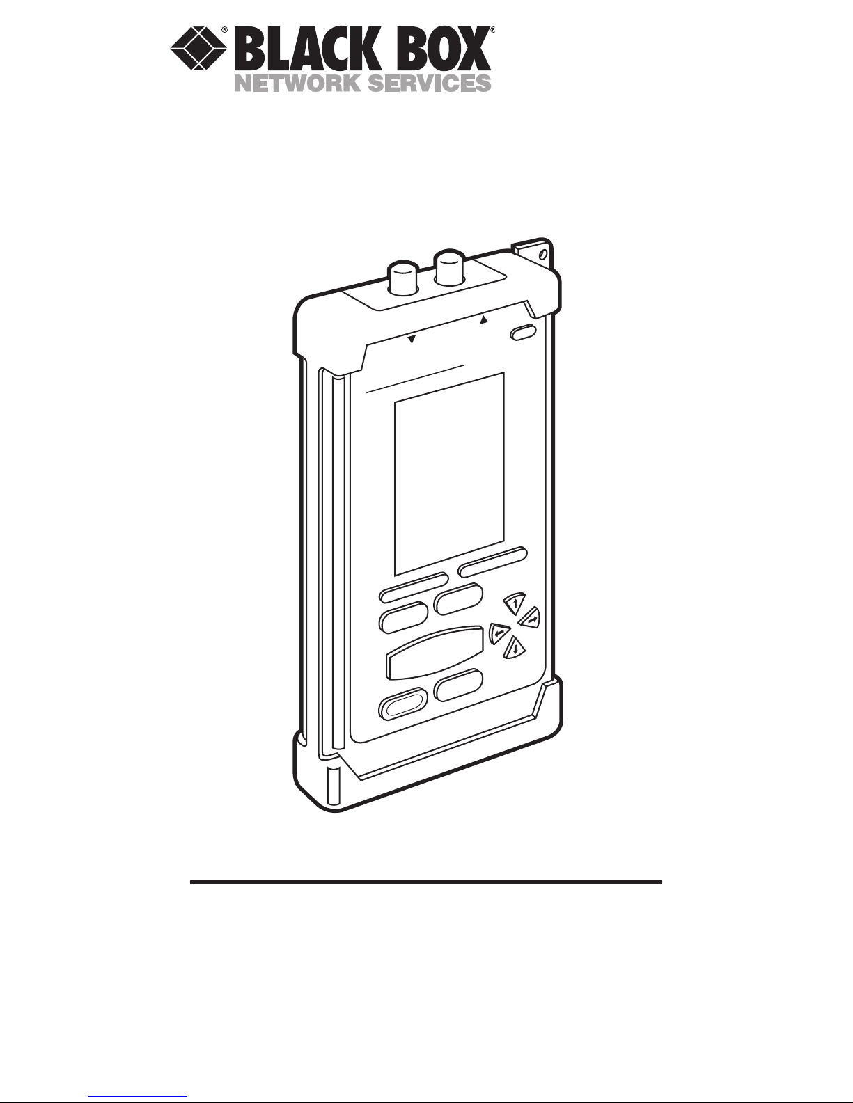
TS655A
RX2
TX1
ON/OFF
F1
F2
Escape
SETUP
Power Meter
SOURCE
Enter
Shift
AUTOTEST
SET REFERENCE
PAGE UP
PAGE DOWN
CertiFiber
CertiFiber
CertiFiber™
CUSTOMER SUPPORT INFORMATION
Order toll-free in the U.S.: Call 877-877-BBOX (outside U.S. call 724-746-5500)
FREE technical support 24 hours a day, 7 days a week: Call 724-746-5500 or
fax 724-746-0746
Mailing address: Black Box Corporation, 1000 Park Drive, Lawrence, PA 15055-1018
Web site: www.blackbox.com • E-mail: info@blackbox.com
Page 2
NORMAS OFICIALES MEXICANAS (NOM)
ELECTRICAL SAFETY STATEMENT
INSTRUCCIONES DE SEGURIDAD
1. Todas las instrucciones de seguridad y operación deberán ser
leídas antes de que el aparato eléctrico sea operado.
2. Las instrucciones de seguridad y operación deberán ser
guardadas para referencia futura.
3. Todas las advertencias en el aparato eléctrico y en sus
instrucciones de operación deben ser respetadas.
4. Todas las instrucciones de operación y uso deben ser
seguidas.
5. El aparato eléctrico no deberá ser usado cerca del agua—por
ejemplo, cerca de la tina de baño, lavabo, sótano mojado o
cerca de una alberca, etc..
6. El aparato eléctrico debe ser usado únicamente con carritos o
pedestales que sean recomendados por el fabricante.
7. El aparato eléctrico debe ser montado a la pared o al techo
sólo como sea recomendado por el fabricante.
8. Servicio—El usuario no debe intentar dar servicio al equipo
eléctrico más allá a lo descrito en las instrucciones de
operación. Todo otro servicio deberá ser referido a personal
de servicio calificado.
9. El aparato eléctrico debe ser situado de tal manera que su
posición no interfiera su uso. La colocación del aparato
eléctrico sobre una cama, sofá, alfombra o superficie similar
puede bloquea la ventilación, no se debe colocar en libreros o
gabinetes que impidan el flujo de aire por los orificios de
ventilación.
10. El equipo eléctrico deber ser situado fuera del alcance de
fuentes de calor como radiadores, registros de calor, estufas u
otros aparatos (incluyendo amplificadores) que producen
calor
.
11. El aparato eléctrico deberá ser connectado a una fuente de
poder sólo del tipo descrito en el instructivo de operación, o
como se indique en el aparato.
12. Precaución debe ser tomada de tal manera que la tierra fisica
y la polarización del equipo no sea eliminada.
13. Los cables de la fuente de poder deben ser guiados de tal
manera que no sean pisados ni pellizcados por objetos
colocados sobre o contra ellos, poniendo particular atención a
los contactos y receptáculos donde salen del aparato.
3
NOM STATEMENT
Page 3
14. El equipo eléctrico debe ser limpiado únicamente de acuerdo
a las recomendaciones del fabricante.
15. En caso de existir, una antena externa deberá ser localizada
lejos de las lineas de energia.
16. El cable de corriente deberá ser desconectado del cuando el
equipo no sea usado por un largo periodo de tiempo.
17. Cuidado debe ser tomado de tal manera que objectos
liquidos no sean derramados sobre la cubierta u orificios de
ventilación.
18. Servicio por personal calificado deberá ser provisto cuando:
A: El cable de poder o el contacto ha sido dañado; u
B: Objectos han caído o líquido ha sido derramado dentro
del aparato; o
C: El aparato ha sido expuesto a la lluvia; o
D: El aparato parece no operar normalmente o muestra un
cambio en su desempeño; o
E: El aparato ha sido tirado o su cubierta ha sido dañada.
CERTIFIBER™
4
Page 4
CONTENTS
1. Specifications ............................................ 7
2. Introduction ........................................... 10
2.1 The Complete Fiber Solution ......... 10
2.2 Standard Features ........................... 11
2.3 The CertiFiber Illustrated ............... 12
2.4 The CertiFiber Main Unit ............... 14
2.4.1 The User Interface ................ 14
2.4.2 The Keypad ........................... 15
2.5 The CertFiber Remote .................... 17
2.5.1 The LEDs .............................. 17
2.5.2 The Keypad ........................... 18
2.6 The Unit’s Batteries ........................ 19
2.7 Displaying Product Information
About CertiFiber .......................... 19
2.8 Editing with CertiFiber ................... 20
2.9 Getting Started ................................ 21
2.10 Display Contrast.............................. 22
2.11 Calibrating CertiFiber ................... 23
3. Configuration ......................................... 24
3.1 Autotests ........................................... 24
3.1.1 Selecting an
Autotest Standard ............... 24
3.1.2 Editing Autotests ................... 25
3.1.3 Test Mode ............................... 27
3.1.4 Job Names .............................. 28
3.2 Length Measurements:
Meters vs. Feet............................... 29
3.3 Time/Date ........................................ 29
3.4 Owner’s Name ................................. 31
3.5 Fiber GRI ......................................... 32
3.6 Language ......................................... 33
3.7 Upload to PC ................................... 33
5
TABLE OF CONTENTS
Page 5

CONTENTS (continued)
4.
Operation: Automatic Measurements
...... 34
4.1 Setting the Reference ...................... 34
4.1.1 In Normal Operation ............ 34
4.1.2 In Loopback Mode ................ 36
4.2 Regular Autotesting ......................... 37
4.2.1 The Autotest Results
Screen .................................. 41
4.2.2 Saving a Autotest ................... 42
4.2.3 Viewing Results ..................... 43
4.2.4 Storing Results ....................... 46
4.2.5 Deleting Results ..................... 47
4.2.6 Uploading Results to a PC .... 48
4.2.7 Printing Results ..................... 49
4.2.8 Sample Autotest-
Certification Report ........... 49
4.3 Loopback-Mode Autotesting ........... 52
5. Operation: Manual Measurements ....... 54
5.1 Power Loss ....................................... 54
5.2 Loopback .......................................... 55
5.3 Light Source .................................... 56
5.3.1 Local ...................................... 56
5.3.2 Remote ................................... 58
6. Troubleshooting ..................................... 59
6.1 Calling Black Box ............................ 59
6.2 Shipping and Packaging ................. 60
Appendix: PASS/FAIL Criteria .................... 61
Legal Information ........................................ 62
CERTIFIBER™
6
Page 6
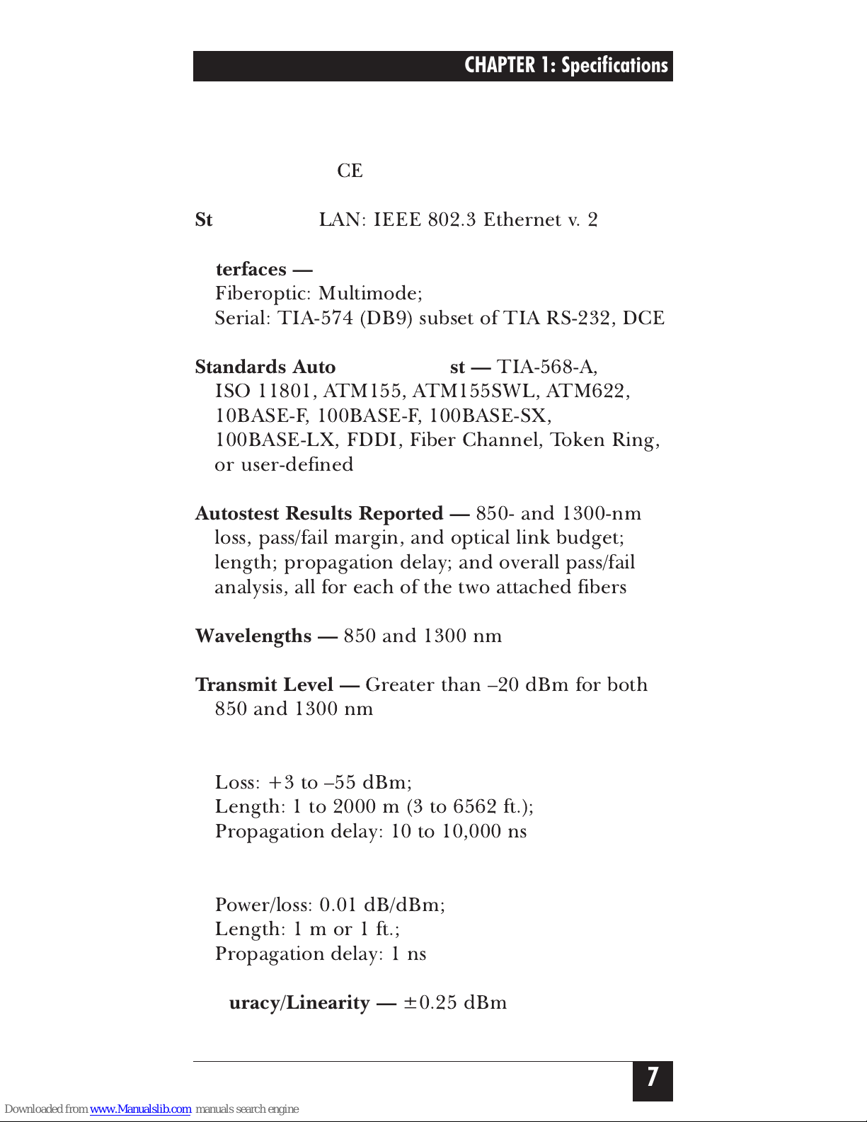
1. Specifications
Compliance —
CE
Standards —
LAN: IEEE 802.3 Ethernet v. 2
Interfaces —
Fiberoptic: Multimode;
Serial: TIA-574 (DB9) subset of TIA RS-232, DCE
Standards Autotested Against —
TIA-568-A,
ISO 11801, ATM155, ATM155SWL, ATM622,
10BASE-F, 100BASE-F, 100BASE-SX,
100BASE-LX, FDDI, Fiber Channel, Token Ring,
or user-defined
Autostest Results Reported —
850- and 1300-nm
loss, pass/fail margin, and optical link budget;
length; propagation delay; and overall pass/fail
analysis, all for each of the two attached fibers
Wavelengths —
850 and 1300 nm
Transmit Level —
Greater than –20 dBm for both
850 and 1300 nm
Dynamic Range —
Loss: +3 to –55 dBm;
Length: 1 to 2000 m (3 to 6562 ft.);
Propagation delay: 10 to 10,000 ns
Resolution —
Power/loss: 0.01 dB/dBm;
Length:1mor1ft.;
Propagation delay: 1 ns
Accuracy/Linearity —
±0.25 dBm
7
CHAPTER 1: Specifications
Page 7
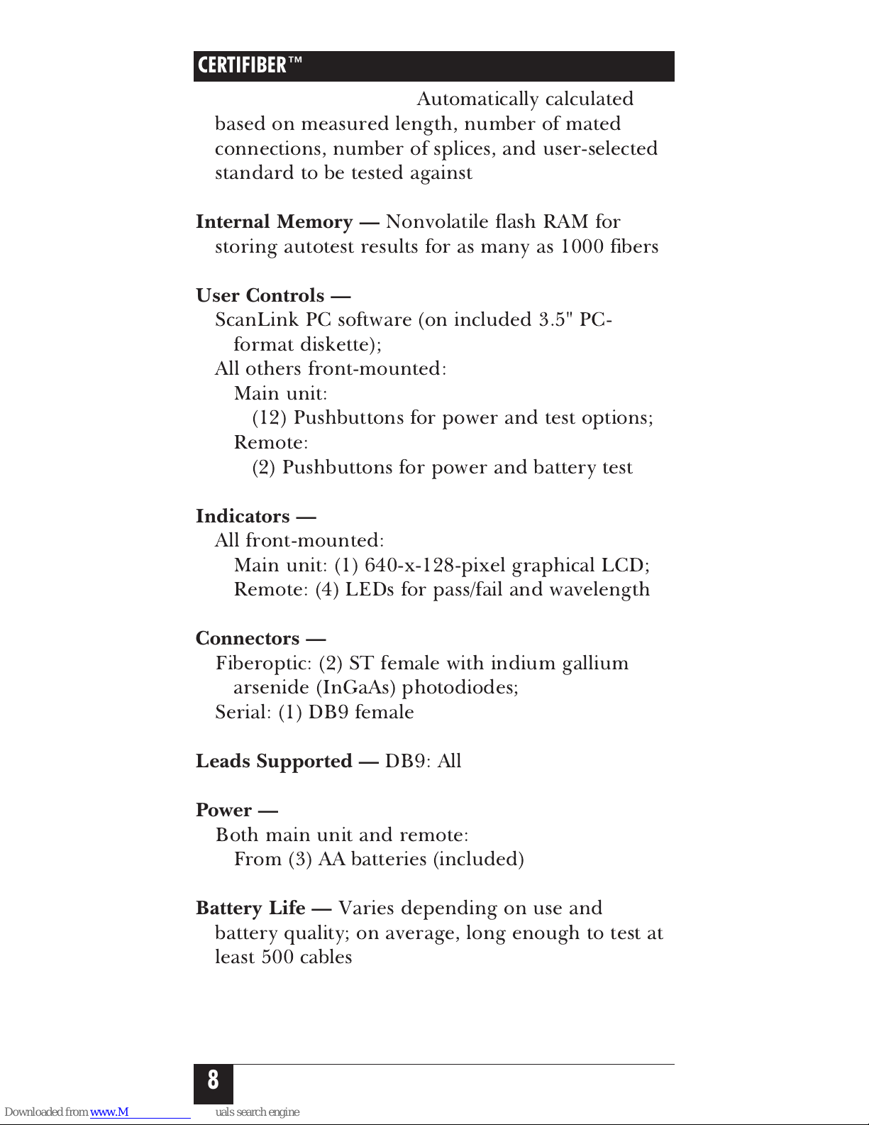
Optical Link Budget —
Automatically calculated
based on measured length, number of mated
connections, number of splices, and user-selected
standard to be tested against
Internal Memory —
Nonvolatile flash RAM for
storing autotest results for as many as 1000 fibers
User Controls —
ScanLink PC software (on included 3.5" PC-
format diskette);
All others front-mounted:
Main unit:
(12) Pushbuttons for power and test options;
Remote:
(2) Pushbuttons for power and battery test
Indicators —
All front-mounted:
Main unit: (1) 640-x-128-pixel graphical LCD;
Remote: (4) LEDs for pass/fail and wavelength
Connectors —
Fiberoptic: (2) ST female with indium gallium
arsenide (InGaAs) photodiodes;
Serial: (1) DB9 female
Leads Supported —
DB9: All
Power —
Both main unit and remote:
From (3) AA batteries (included)
Battery Life —
Varies depending on use and
battery quality; on average, long enough to test at
least 500 cables
CERTIFIBER™
8
Page 8

Temperature Tolerance —
Operating: 32 to 113˚ F (0 to 45˚ C);
Storage: –4 to 140˚ F (–20 to 60˚ C)
Humidity Tolerance —
Operating: 5 to 90% noncondensing;
Storage: 5 to 95% noncondensing
Size —
Both main unit and remote:
7.1"H x 3.1"W x 1.6"D (18 x 7.9x4cm)
Weight —
Main unit: 14.9 oz. (0.9 lb., 422 g, 0.4 kg);
Remote: 13.4 oz. (0.8 lb., 380 g, 0.4 kg)
9
CHAPTER 1: Specifications
Page 9
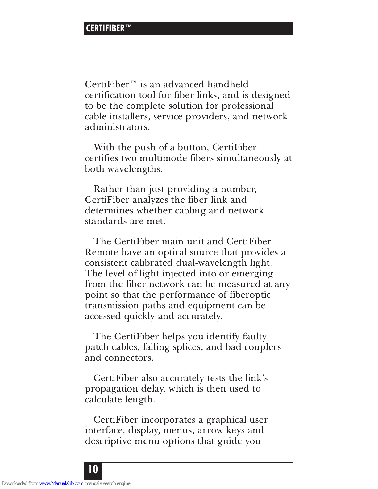
2. Introduction
2.1 The Complete Fiber Solution
CertiFiber™ is an advanced handheld
certification tool for fiber links, and is designed
to be the complete solution for professional
cable installers, service providers, and network
administrators.
With the push of a button, CertiFiber
certifies two multimode fibers simultaneously at
both wavelengths.
Rather than just providing a number,
CertiFiber analyzes the fiber link and
determines whether cabling and network
standards are met.
The CertiFiber main unit and CertiFiber
Remote have an optical source that provides a
consistent calibrated dual-wavelength light.
The level of light injected into or emerging
from the fiber network can be measured at any
point so that the performance of fiberoptic
transmission paths and equipment can be
accessed quickly and accurately.
The CertiFiber helps you identify faulty
patch cables, failing splices, and bad couplers
and connectors.
CertiFiber also accurately tests the link’s
propagation delay, which is then used to
calculate length.
CertiFiber incorporates a graphical user
interface, display, menus, arrow keys and
descriptive menu options that guide you
CERTIFIBER™
10
Page 10
11
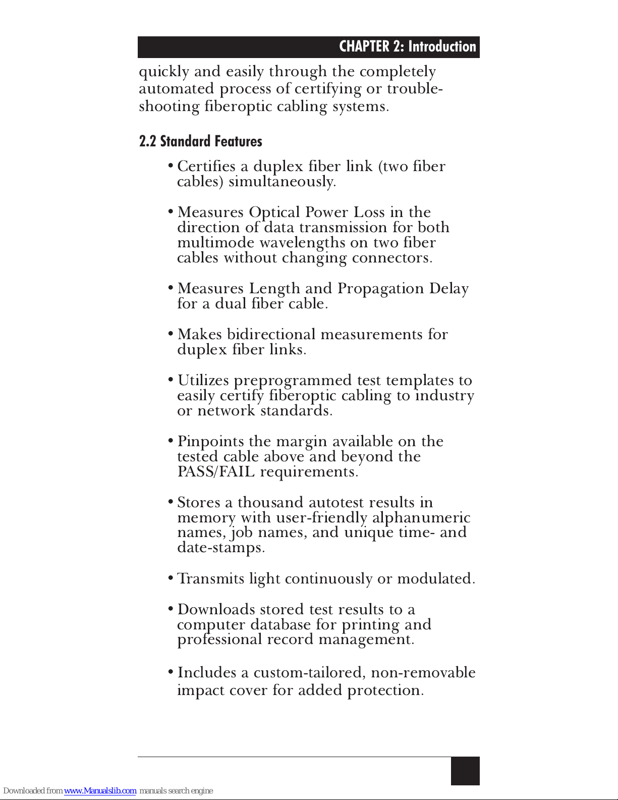
quickly and easily through the completely
automated process of certifying or trouble-
shooting fiberoptic cabling systems.
2.2 Standard Features
•Certifies a duplex fiber link (two fiber
cables) simultaneously.
•Measures Optical Power Loss in the
direction of data transmission for both
multimode wavelengths on two fiber
cables without changing connectors.
•Measures Length and Propagation Delay
for a dual fiber cable.
•Makes bidirectional measurements for
duplex fiber links.
•Utilizes preprogrammed test templates to
easily certify fiberoptic cabling to industry
or network standards.
•Pinpoints the margin available on the
tested cable above and beyond the
PASS/FAIL requirements.
•Stores a thousand autotest results in
memory with user-friendly alphanumeric
names, job names, and unique time- and
date-stamps.
•
Transmits light continuously or modulated.
•Downloads stored test results to a
computer database for printing and
professional record management.
•
Includes a custom-tailored, non-removable
impact cover for added protection.
CHAPTER 2: Introduction
Page 11
CERTIFIBER™
12
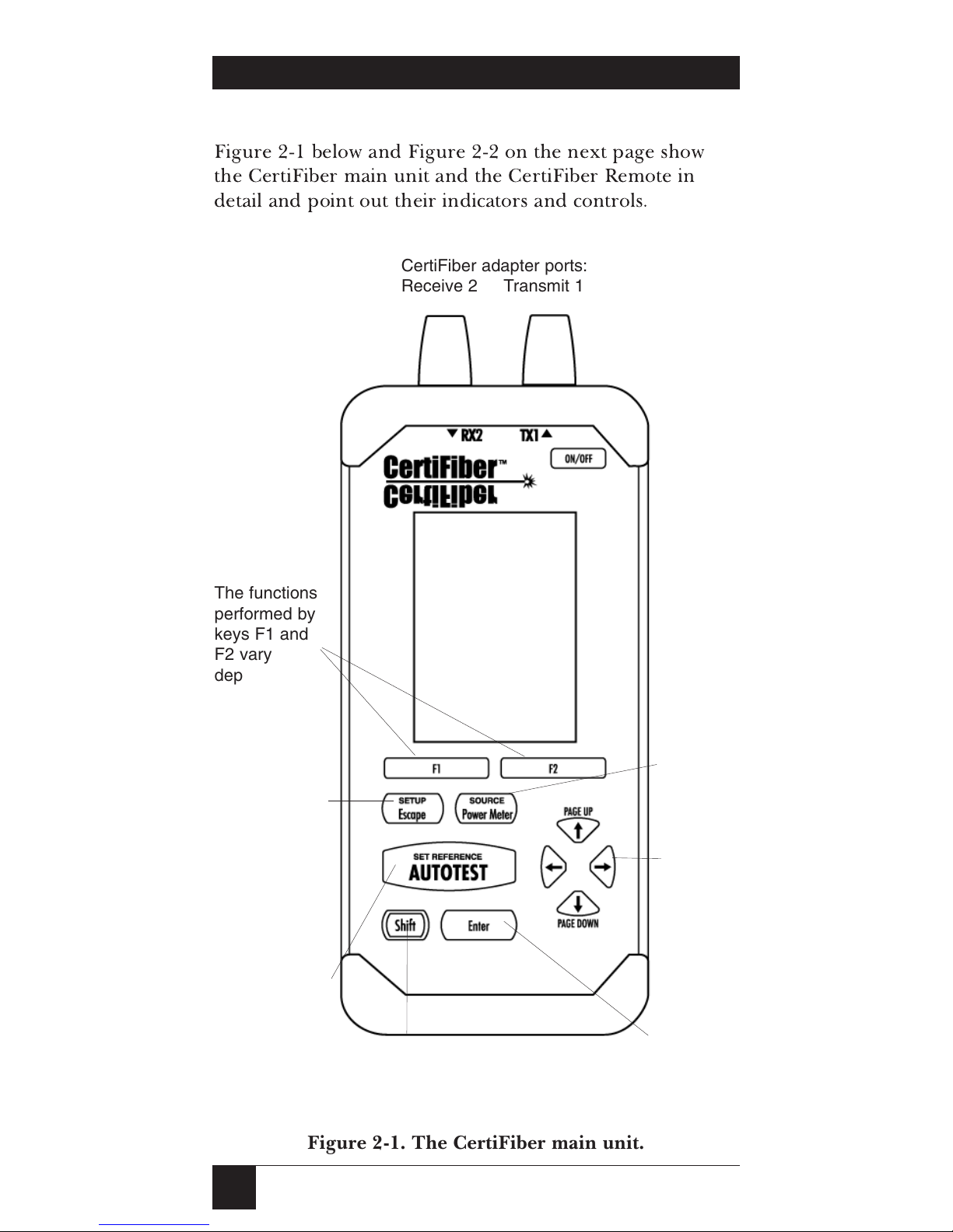
2.3 The CertiFiber Illustrated
Figure 2-1 below and Figure 2-2 on the next page show
the CertiFiber main unit and the CertiFiber Remote in
detail and point out their indicators and controls.
Figure 2-1. The CertiFiber main unit.
CertiFiber adapter ports:
Receive 2 Transmit 1
The functions
performed by
keys F1 and
F2 vary
depending on
the screen
being
displayed.
Graphical
LCD panel
The Escape
key exits the
current display
or function;
Shirt + Escape
opens the
SETUP
screen.
Press the
Autotest key to
perform tests,
or Shirt +
Autotest to set
the reference.
Press the Shift key
together with other keys
for extended functions.
Use the Arrow
keys to
navigate
among the
displays.
Press Enter to
execute a command.
Use the Power
Meter key for
nonautomated
measurements;
Shift + Power
Meter activates
the unit’s light
source.
Page 12
13
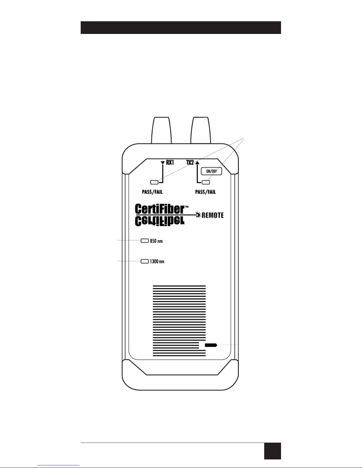
Figure 2-2. The CertiFiber Remote.
CHAPTER 2: Introduction
CertiFiber Remote adapter ports:
Receive 1 Transmit 2
Press the
Battery Test
key to get a
rough idea
how much life
is left in your
batteries.
Test
PASS/FAIL
LEDs.
The Wavelength LEDs
show which
fiber wavelength (850
or 1300 nm)
is currenty
selected.
Page 13
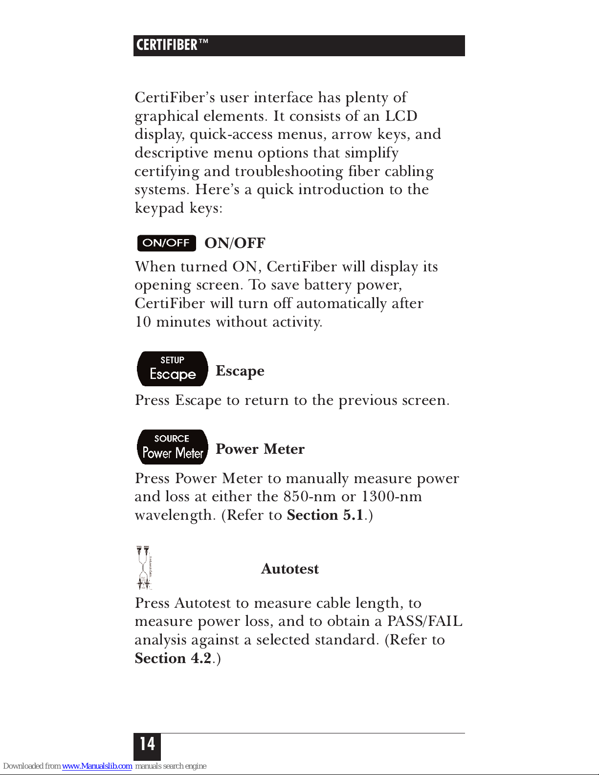
2.4 The CertiFiber Main Unit
CertiFiber’s user interface has plenty of
graphical elements. It consists of an LCD
display, quick-access menus, arrow keys, and
descriptive menu options that simplify
certifying and troubleshooting fiber cabling
systems. Here’s a quick introduction to the
keypad keys:
ON/OFF
When turned ON, CertiFiber will display its
opening screen. To save battery power,
CertiFiber will turn off automatically after
10 minutes without activity.
Escape
Press Escape to return to the previous screen.
Power Meter
Press Power Meter to manually measure power
and loss at either the 850-nm or 1300-nm
wavelength. (Refer to
Section 5.1
.)
Autotest
Press Autotest to measure cable length, to
measure power loss, and to obtain a PASS/FAIL
analysis against a selected standard. (Refer to
Section 4.2
.)
CERTIFIBER™
14
Page 14
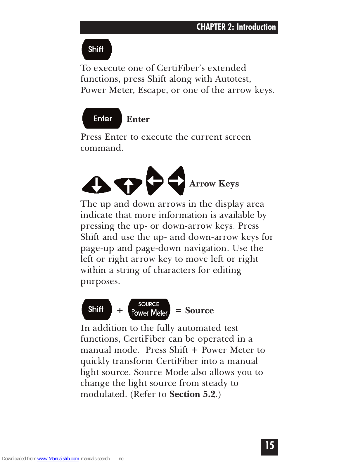
Shift
To execute one of CertiFiber’s extended
functions, press Shift along with Autotest,
Power Meter, Escape, or one of the arrow keys.
Enter
Press Enter to execute the current screen
command.
Arrow Keys
The up and down arrows in the display area
indicate that more information is available by
pressing the up- or down-arrow keys. Press
Shift and use the up- and down-arrow keys for
page-up and page-down navigation. Use the
left or right arrow key to move left or right
within a string of characters for editing
purposes.
+ = Source
In addition to the fully automated test
functions, CertiFiber can be operated in a
manual mode. Press Shift + Power Meter to
quickly transform CertiFiber into a manual
light source. Source Mode also allows you to
change the light source from steady to
modulated. (Refer to
Section 5.2
.)
15
CHAPTER 2: Introduction
Page 15
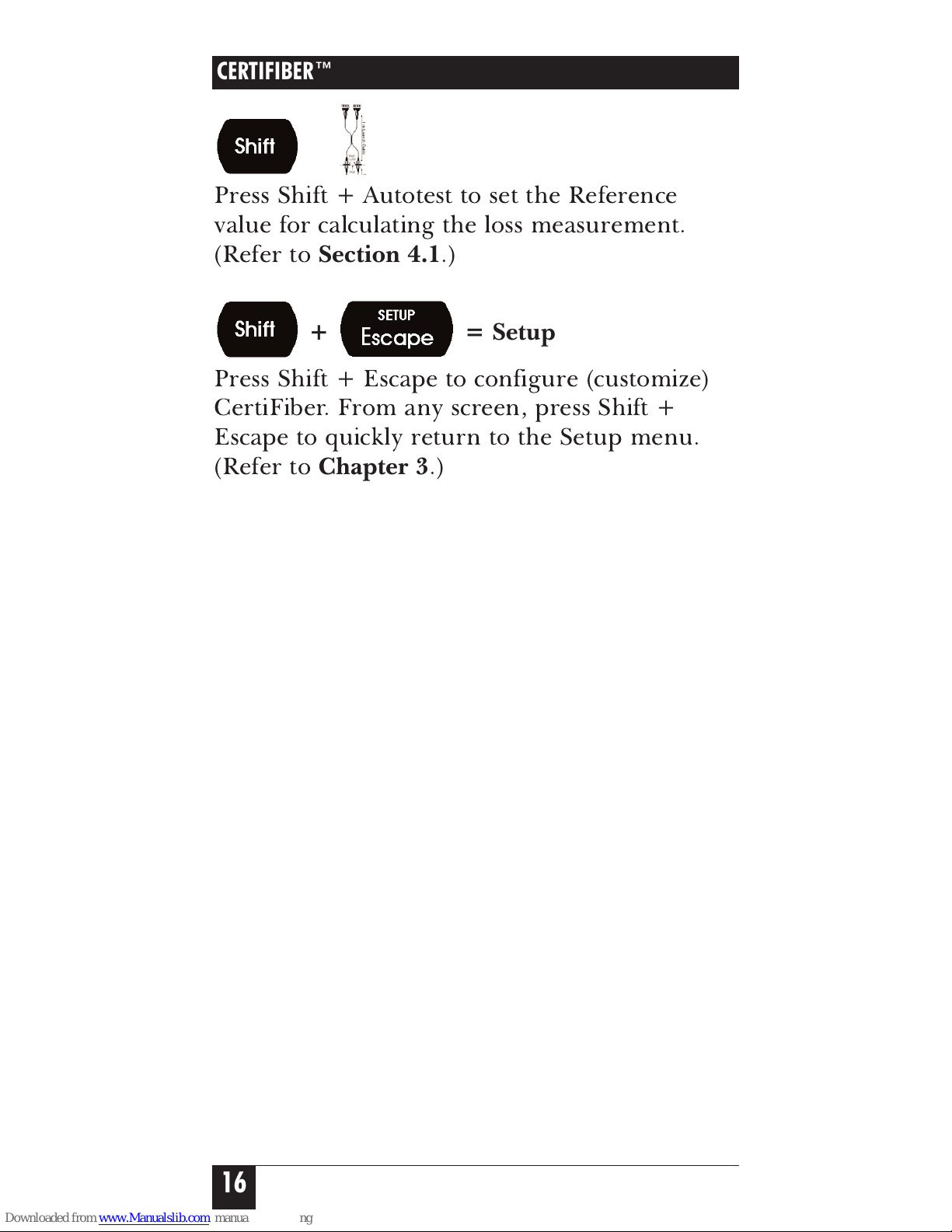
+ = Set Reference
Press Shift + Autotest to set the Reference
value for calculating the loss measurement.
(Refer to
Section 4.1
.)
+ = Setup
Press Shift + Escape to configure (customize)
CertiFiber. From any screen, press Shift +
Escape to quickly return to the Setup menu.
(Refer to
Chapter 3
.)
CERTIFIBER™
16
Page 16
2.5 The CertiFiber Remote
The CertiFiber Remote is an active and
intelligent far-end device that works with the
CertiFiber main unit to verify optical-cable
transmission quality. All information is
processed and transferred to the main unit.
Both units provide a consistent, calibrated light
source that increases the ease and effectiveness
of fiberoptic testing.
2.5.1 THELED
S
The CertiFiber Remote has four LED
indicators:
LED Name Color Description
RX1 PASS/FAIL red Fiber 1 has failed
green Fiber 1 has passed
TX2 PASS/FAIL red Fiber 2 has failed
green Fiber 2 has passed
850nm* green CertiFiber Remote is
transmitting at 850nm
1300nm* green CertiFiber Remote is
transmitting at 1300nm
* Press and hold the Battery button.
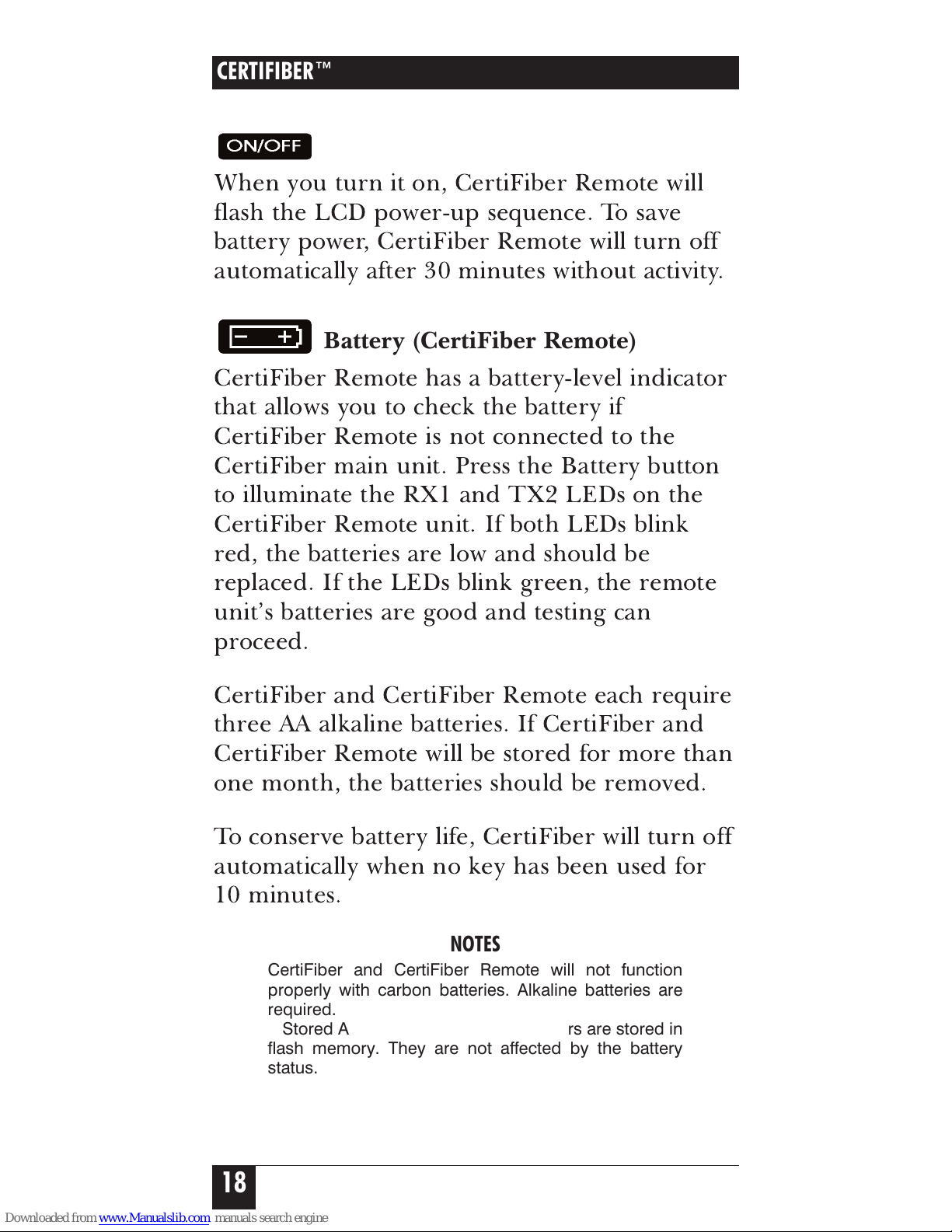
The LEDs also show the results of a battery test
(which you run by pressing the Battery
button):
RX1 and TX2 LEDs red Low Battery < 10%
TX2 LED red Battery 10 to 25%
RX1 LED green Battery 25% to 75%
RX1 and TX2 LEDs green Good Battery > 75%
RX1 and TX2 LEDs* yellow Part 1 of Two Way
Autotest completed
*Switch fiber connectors: RX2 to TX1, TX1 to RX2, RX1 to
TX2, TX2 to RX1.
17
CHAPTER 2: Introduction
Page 17
2.5.2 THEK
EYPAD
ON/OFF (CertiFiber Remote)
When you turn it on, CertiFiber Remote will
flash the LCD power-up sequence. To save
battery power, CertiFiber Remote will turn off
automatically after 30 minutes without activity.
Battery (CertiFiber Remote)
CertiFiber Remote has a battery-level indicator
that allows you to check the battery if
CertiFiber Remote is not connected to the
CertiFiber main unit. Press the Battery button
to illuminate the RX1 and TX2 LEDs on the
CertiFiber Remote unit. If both LEDs blink
red, the batteries are low and should be
replaced. If the LEDs blink green, the remote
unit’s batteries are good and testing can
proceed.
CertiFiber and CertiFiber Remote each require
three AA alkaline batteries. If CertiFiber and
CertiFiber Remote will be stored for more than
one month, the batteries should be removed.
To conserve battery life, CertiFiber will turn off
automatically when no key has been used for
10 minutes.
NOTES
CertiFiber and CertiFiber Remote will not function
properly with carbon batteries. Alkaline batteries are
required.
Stored Autotests and setup parameters are stored in
flash memory. They are not affected by the battery
status.
CERTIFIBER™
18
Page 18
19
2.6 The Unit’s Batteries
To check CertiFiber’s battery:
1. Connect the CertiFiber to the Remote
unit using a launch cable.
2. Turn both units on.
3. Press F2 to display the About screen. This
screen displays CertiFiber and CertiFiber
Remote’s remaining battery power
(“Battery”), as well as other info (see the
next section).
To change batteries, slide off the battery cover
located on the back of each unit. Replace the
three AA alkaline batteries and position the
replacements according to the display in the
battery case.
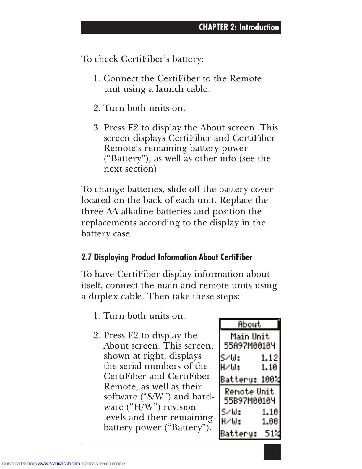
2.7 Displaying Product Information About CertiFiber
To have CertiFiber display information about
itself, connect the main and remote units using
a duplex cable. Then take these steps:
1. Turn both units on.
2. Press F2 to display the
About screen. This screen,
shown at right, displays
the serial numbers of the
CertiFiber and CertiFiber
Remote, as well as their
software (“S/W”) and hard-
ware (“H/W”) revision
levels and their remaining
battery power (“Battery”).
CHAPTER 2: Introduction
Page 19
3. Press Escape to return to the Setup
screen.
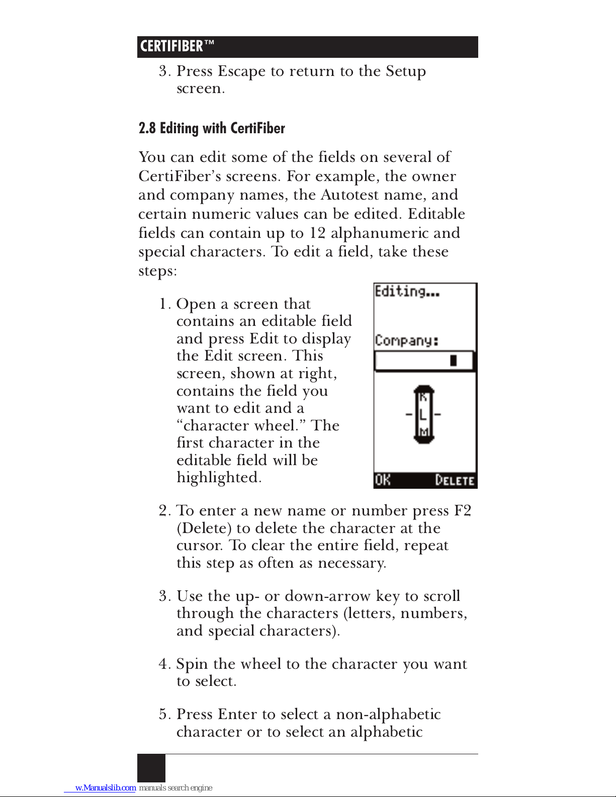
2.8 Editing with CertiFiber
You can edit some of the fields on several of
CertiFiber’s screens. For example, the owner
and company names, the Autotest name, and
certain numeric values can be edited. Editable
fields can contain up to 12 alphanumeric and
special characters. To edit a field, take these
steps:
1. Open a screen that
contains an editable field
and press Edit to display
the Edit screen. This
screen, shown at right,
contains the field you
want to edit and a
“character wheel.” The
first character in the
editable field will be
highlighted.
2. To enter a new name or number press F2
(Delete) to delete the character at the
cursor. To clear the entire field, repeat
this step as often as necessary.
3. Use the up- or down-arrow key to scroll
through the characters (letters, numbers,
and special characters).
4. Spin the wheel to the character you want
to select.
5. Press Enter to select a non-alphabetic
character or to select an alphabetic
CERTIFIBER™
20
YOUR_CO
Page 20
21
character as a
lowercase
letter, or press
Shift + Enter to select an alphabetic
character as an
uppercase
letter. The
highlight will move to the next position in
the field automatically. If you make a
mistake, press F2 (Delete) to erase the
character and back up.
6. Repeat steps 3 through 5 until the field is
completed.
7. Press F1 (OK) or Escape to exit the Edit
screen.
2.9 Getting Started
With CertiFiber, you can certify a fiber link in
seconds using the one-button Autotest. To run
an Autotest, take these steps (see
Section 4.2
for more detailed information):
1. Set the reference value (refer to
Section 4.1
).
2. Remove the covers from the
ST connectors on the CertiFiber and
CertiFiber Remote.
CAUTION!
Both units come with covers on their ST connectors to
protect the connectors from dirt and other foreign
matter. Keep the connectors covered when the units
are not in use. This helps to ensure that contaminants
do not affect test measurements.
3. Attach the cable to be tested to CertiFiber
and CertiFiber Remote’s ST connectors.
Run one fiber from RX2 to TX2, the
other from TX1 to RX1.
CAUTION!
Improperly polished or manufactured fiber-connector
ferrules can damage the CertiFiber’s transmit LED. To
avoid out-of-warranty repairs, please use cables with
clean, properly polished ST connectors.
CHAPTER 2: Introduction
Page 21
3. Select a fiber standard. TIA-568-A and
ISO 11801 are the most widely used fiber
standards.
4. Press the Autotest button.
5. Enter the number of splices and
connectors.
6. Press F1 (Run). CertiFiber will now run
the length, propagation delay, and dual
fiber-loss measurements for 850 nm and
1300 nm and provide a PASS/FAIL
analysis based on the chosen fiber
standard.
7. Press F1 (Save) to name and store the test
result for each fiber.
8. Press F2 (View) to display test results and
move between fibers.
9 Put the covers back on the
ST connectors on the CertiFiber and
CertiFiber Remote.
Test results can now be viewed in the Results
screen. To print test results, they need to be
uploaded to a PC using the included
ScanLink®software. Refer to
Section 4.2.3
.
2.10 Display Contrast
CertiFiber’s display contrast can be adjusted.
From the logo screen, press Shift + up-arrow
or down-arrow to increase or decrease the
contrast.
CERTIFIBER™
22
Page 22

NOTE
The display contrast returns to the default setting when
the unit is turned off.
2.11 Calibrating CertiFiber
CertiFiber and CertiFiber Remote should be
calibrated annually by the manufacturer with
specialized equipment. Contact Black Box
Technical Support for information on
calibration and service requirements.
23
CHAPTER 2: Introduction
Page 23

24
3. Configuration
Press
+
to
display the main Setup screen.
Use the up- or down-arrow
keys to highlight a setup
feature. Press Enter to display
the relevant setup screen. Press
Escape to return to the
CertiFiber logo screen.
3.1 Autotests
3.1.1 S
ELECTING ANAUTOTESTSTANDARD
CertiFiber certifies fiber links
based on the common standard
TIA-568-A and the international
standard ISO 11801, as well as
common LAN cabling
standards such as FDDI, Fiber
Channel and other application-
specific fiber requirements. (See
the
Standards Autotested
Against
specification in
Chapter 1
for a complete list of
supported network types.) To
select an Autotest standard, take these steps:
1 To display the Autotest screen, highlight
Autotest in the Setup screen and press
Enter or F1 (Select).
2. Use the up- or down-arrow keys to scroll
through the list of Autotests.
CERTIFIBER™
Page 24

3. Highlight the preferred Autotest and
press F1 (Select) to select it as the Autotest
to run and to return to the Setup screen.
3.1.2 E
DITINGAUTOTESTS
In addition to the pre-programmed
certification standards, CertiFiber allows you to
customize Autotest settings and to develop new
custom Autotests by specifying the PASS/FAIL
limits to be used. To edit an Autotest, take
these steps:
1. From the Autotest setup
screen, use the up- or
down-arrows to highlight
the Autotest you want to
customize and then press
F2 (Edit). A screen like
the one shown at right
appears. If you are
editing an existing
Autotest, the test name
will be preceded with an
asterisk (“*”).
2. With the Test Name field highlighted,
press F1 (Edit) to name the Autotest.
Refer to
Section 2.8
.
3. Edit the other test values. (Editable fields
for an
equation-based
Autotest are the Test
Name, the Loss per Connector, the Loss
per Splice, the Loss per Kilometer for
both wavelengths, the Length, and the
Delay. Editable fields for an Autotest with
fixed PASS/FAIL criteria
are the Test Name,
the Loss per Kilometer for both
wavelengths, the Length and the Delay.)
25
CHAPTER 3: Configuration
Page 25

First press F2 (Select) to highlight the
value you want to edit. Then use the up-
and down-arrow keys to change the
displayed values in small increments such
as 0.1 dB or 1 m, or use the left- and
right-arrow keys to change the displayed
values in large increments such as 1 dB
or 100 m.
4. Press F1 (Save) to open the Overwrite
Autotest screen. It contains a list of four
user-definable Autotest names (User 1,
User 2, User 3, and User 4).
5. Use the up- and down-arrow keys to
highlight one of the four Autotest names
you want to overwrite with the new
testname and settings. (To ensure that the
default Autotests are not overwritten, the
asterisk preceding the names of edited
existing Autotests cannot be removed.)
6. Press F1 (Select) to save the Autotest and
list the new test name in the Autotest
screen.
7. Press F1 (Select) to select the highlighted
Autotest as the test to run and return to
the Autotest-Setup screen.
CERTIFIBER™
26
Page 26

3.1.3 T
ESTMODE
CertiFiber allows you to control the test
direction. Dual fibers can be tested in opposite
single direction or in both directions. Choose
One Way
to measure a duplex fiber link or
choose
Two Way
to measure a duplex fiber
link in both directions (bidirectional test).
1. To display the
Test Mode
screen, use the up-arrow
to scroll to
Test Mode
in
the
Setup
screen and
press
Enter
or
F1
(Select)
.
The display shows the
currently selected test
mode.
2. Press
F2 (Change)
to
change the test mode.
3. Press
F1 (Save)
to save the setting and
return to the
Setup
screen.
27
CHAPTER 3: Configuration
Page 27

3.1.4 JOBN
AMES
CertiFiber allows you to assign predefined or
customized Job Names so that you can
uniquely identify different job sites, for
example, Project 1 has 102 fiber test results
stored, etc.
1. To display the
Job
Names
setup screen,
use the up-arrow to
scroll to
Job Names
in
the
Setup
screen and
press
Enter
or
F1
(Select)
.
2. Use the up-arrow or
down-arrow to scroll
through the list of job
names.
3. Highlight a Job Name and press
(F2) Edit
to customize it with up to 10 characters.
4. Highlight the Job Name you want to use
and press
Enter
or
F1 (Save)
to save the
list of Job Names.
If you choose not to use Job Names, the first
item in the Job Name list will automatically
default to
Not Used
when an Autotest is saved.
CERTIFIBER™
28
Page 28

3.2 Length Measurements: Meters vs. Feet
You can change CertiFiber’s
length-measurement unit from
meters to feet and vice versa.
To do so, take these steps:
1. To display the Meters/Feet
setup screen, use the
down-arrow key to scroll
to Meters/Feet in the main
Setup screen and press
Enter or F1 (Select). The
display will show the
currently selected
measurement unit.
2. Press F2 to toggle the measurement
setting between meters and feet, or use
the up- or down-arrow keys to change the
measurement unit.
3. Press F1 (Save) to save the setting and
return to the main Setup screen.
3.3 Time/Date
You can set the date and time
of the CertiFiber’s internal
clock. CertiFiber will maintain
these settings until either you
change them again or the unit’s
battery is removed for more
than one hour. To set the date
and time, take these steps:
1. To display the Time/Date
setup screen, use the
down-arrow key to scroll
29
CHAPTER 3: Configuration
Page 29

to Time/Date in the Setup screen and
press Enter or F1 (Select).
2. Use the left- and right-arrow keys to
scroll through the segments in the screen.
3. Select a portion of the time or date field
to change.
4. Use the up- or down-arrow key to change
the value in that field segment. (All fields
are editable in increments of 1 unit. Hold
down the up- or down-arrow key to scroll
through the possible values more quickly.)
5. CertiFiber has two time displays available:
12-hour (a.m./p.m.) or 24-hour (military-
time) clock. You can toggle back and forth
between these displays by moving the
cursor to the clock-type field. Use the up-
or down-arrow key to select the 12- or
24-hour option.
6. Press F1 (Save) to save the new settings
and return to the Setup screen.
30
CERTIFIBER™
Page 30

3.4 Owner’s Name
You can also change the owner
and company names that
appear on the logo screen of
the CertiFiber and on printed
reports. To do so, take these
steps:
1. To display the Owner
Name setup screen, use
the down-arrow key to
scroll to Owner Name in
the Setup screen and
press Enter or F1 (Select).
2. Use the up- or down-arrow key to
highlight the Company Name.
3. With the Company Name highlighted,
press F2 (Edit).
4. The Edit screen will appear with the
cursor in the Company Name field.
Follow the directions in
Section 2.8
to
edit this field as desired.
5. Now highlight the Operator Name and
press F2 (Edit).
6. The Edit screen will appear again, this
time with the cursor in the Operator
Name field. Follow the directions in
Section 2.8
to edit this field as desired.
7. Press F1 (Save) to save the names and
return to the Setup screen.
31
CHAPTER 3: Configuration
YOUR_CO
Page 31

32
3.5 Fiber GRI
The Graded Refractive Index
(GRI) of fiber cables differs
depending on the
manufacturer. So that you can
get accurate length results for
different cables, CertiFiber has
user-definable GRI values for
both test wavelengths.
The default GRI values used
for a 62.5-micron cable are
1.5014 at 850 nm and 1.4966 at
1300 nm. If you are using 50-micron cable and
do not have the GRI values published by the
fiber manufacturer, the defaults should be set
to 1.4897 at 850 nm and 1.4856 at 1300 nm.
The standard GRI values for 62.5-micron
fiber produced before 1994 are 1.478 at
850 nm and 1.422 at 1300 nm.
1. To display the Fiber GRI setup screen,
use the down-arrow key to scroll to Fiber
GRI in the Setup screen and press Enter
or F1 (Select).
2. Press F2 (Select) to highlight the GRI to
be changed.
3. Use the up- or down-arrow key to
increase or decrease the value by
.0001 dB, or use the left- or right-arrow
key to increase or decrease the value by
.01 dB.
4. Press F1 (Save) to save the settings and
return to the Setup screen.
CERTIFIBER™
Page 32

3.6 Language
CertiFiber offers a selection of
languages for the screen
display. To choose a different
display language, take these
steps:
1. To display the Language
setup screen, use the
down-arrow key to scroll
to Language in the Setup
screen and press Enter.
2. Use the up- or down-
arrow key to scroll to the appropriate
language.
3. Press Enter or F1 (Select) to select the
highlighted language as the default
language and return to the Setup screen.
3.7 Upload to PC
All test results can be uploaded to a PC using
the included ScanLink software. To display the
Upload to PC setup screen, use the down-
arrow key to scroll to Upload to PC in the
Setup screen and press Enter. For the rest of
the upload procedure, see
Section 4.2.5
.
33
CHAPTER 3: Configuration
Page 33

34
4. Operation: Automatic
Measurements
CAUTION!
All connectors and fiber-end faces need to be clean
prior to testing. Use the appropriate optical cleaning
supplies to keep connectors and adapters free from
contamination.
Both CertiFiber units come with covers on their ST
connectors to protect the connectors from dirt and
other foreign matter. Keep the connectors covered
when the units are not in use. This helps to ensure that
contaminants do not affect test measurements.
4.1 Setting the Reference
4.1.1 INN
ORMALOPERATION
+
Accurate, repeatable measurements of optical
power and signal loss are fundamental for the
installation and maintenance of fiber optics.
To make an accurate measurement, you need
to know the loss in your attached launch cable
and the power being transmitted. (The launch
cable used to set the reference value should be
the same type of fiber as the
cables to be tested and certified,
either 50/125 or 62.5/125.)
The reference value must be
stored before a loss
measurement can be calculated.
CertiFiber requires the
reference value to compensate
for the signal loss in the launch
cable. This value is then
subtracted from the actual
CERTIFIBER™
Page 34

measured value to determine loss.
Once the reference value is
established, consistent readings
for loss, delay, and length
measurements are ensured.
To set the reference value, take
these steps:
1. Connect CertiFiber and
CertiFiber Remote using
the ST-ST launch cables
and couplers as shown at
right.
2. Press Shift + Autotest to
record the reference
value. The Reference
screen shown below will
appear briefly. Once the
reference data has been
saved, the CertiFiber logo
screen will be displayed.
3. Remove the couplers.
NOTES
Once the reference value has been set, make sure that
both launch cables remain attached to the CertiFiber
units. Try to remove the coupler without disturbing
these connections.
If the test configuration changes, a new reference
value needs to be established.
35
CHAPTER 4: Operation: Automatic Measurements
1-m Launch Cable
1-m Launch Cable
Coupler
Page 35

CertiFiber will store a separate reference value
for each wavelength.
The new reference value will be subtracted
from the actual measured value to determine
loss.
CertiFiber will store reference data for up to
five CertiFiber Remote units and one loopback
setup (see the next section).
NOTE
To ensure consistently accurate measurements, the
reference value must be set each calendar day that
CertiFiber is used. The reference value expires each
day at midnight.
4.1.2 INL
OOPBACKMODE
If a single cable needs to be measured, the
reference value can be set for a single launch
cable. To do so, take these steps:
1. Attach one end of the cable
to the CertiFiber main
unit’s TX1 connector, and
the other end to the RX2
connector, as shown at
right.
2. Use a coupler to connect
the Launch cables.
3. Press Shift + Autotest to
record the reference value.
4. Remove the coupler without disturbing
the connection to the CertiFiber.
36
CERTIFIBER™
Coupler
RX2 TX1RX2 TX1
RX2 TX1
1 m Launch Cable
Page 36

4.2 Regular Autotesting
Using its completely automated Autotest
feature, CertiFiber runs cable
tests, checks test results against
standards, and displays a PASS/
FAIL indication.
An Autotest can be easily
customized to run the different
certification tests required for
your site or system.
Autotest supports many
different network types. The
tests and results vary
depending on the type of
network. (See the
Standards
Autotested Against
specification in
Chapter 1
for a
complete list of supported
network types.)
For certain Autotests, the
PASS/FAIL criteria need to be
customized in the Edit Autotest
screen. (Refer to
Section 3.1
.)
To run an Autotest, take
these steps:
1. Attach the cables to
CertiFiber and CertiFiber
Remote as shown at right.
37
CHAPTER 4: Operation: Automatic Measurements
Page 37

2. Press the Autotest key.
At this point, if you are running an equation-
based Autotest (TIA-568-A, ISO 11801, or
100BASE-F), a screen like the one shown below
will be displayed to allow for connector- and
splice-number editing. Take steps 3 through 5
only if
you need to customize the number of
connectors and splices.
3. Press F2 (Select) to toggle the highlight
between the number of connector pairs
and the number of splices.
4. Use the up- and down-arrow keys to
change the number of connector pairs
and splices.
5. After editing these numbers, press F1
(Run) to save the changes and run the
Autotest.
6. The Autotest Results screen (see the next
section) will be displayed while CertiFiber
is verifying both fiberoptic cables.
38
CERTIFIBER™
Page 38

7. To continue the two-way
test, switch the connectors
that attach to the cable
under test as shown in the
graphic.
NOTE
Do not switch the launch cable
connectors that are attached to the
units.
8. Press
F1 (Run)
to
complete the two-way test.
39
CHAPTER 4: Operation: Automatic Measurements
Page 39

During Autotesting, CertiFiber measures
a cable’s Loss, Length, and Delay:
Optical Power Loss is a measurement of the
signal loss in a cable. A signal is injected into
the fiber cable by the Remote unit. CertiFiber
measures the received signal to determine loss.
It displays the loss in decibels (dB), as well as
the margin values, for both wavelengths.
Length measurements are derived from the
propagation-delay results by using the cable’s
GRI (Graded Refractive Index) at the
appropriate wavelength. CertiFiber measures
the full length of the fibers under test. (See
Section 3.5
for information on how to change
the GRI values.) In the Autotest Results screen,
the length is displayed in meters or feet
depending on how your unit is set up. (See
Section 3.2
.)
Propagation Delay is a measurement of the
time required for a signal to advance from one
end of the circuit to the other. When
measuring propagation delay, CertiFiber
measures the round-trip delay through both
fibers, and then divides the result by two,
assuming that the cables are equal in length.
Propagation delay cannot be measured on a
single fiber; duplex fibers must be used. The
Autotest Results screen displays the
Propagation Delay in nanoseconds (ns).
CERTIFIBER™
40
Page 40

4.2.1 THEA
UTOTESTRESULTSSCREEN
The arrows at the top of the
screen indicate whether the
results are for a
One Way
or a
Two Way
test.
The Autotest Results screen
displays the loss for each fiber
at 850 and 1300 nm. For
bidirectional measurements the
Worst case loss is displayed.
NOTE
There is a ±0.25dB margin of error in
all PASS/FAIL indications.
Length and Propagation Delay
will be measured. The values
will then be compared against
the preprogrammed
PASS/FAIL limits and
CertiFiber will provide a
indication for both fibers.
The first page of the screen
displays the results for Fiber 1.
Use the right-arrow key to
highlight and display the
results for Fiber 2.
To save the highlighted
Autotest result, press
F1 (Save)
.
To view all results for the highlighted Autotest,
press
F2 (View)
.
41
CHAPTER 4: Operation: Automatic Measurements
Page 41

4.2.2 S
AVING ANAUTOTEST
To save the results of an Autotest, take these
steps:
1. Highlight Fiber 1 on the RX side or Fiber
2 on the TX side and press F1 (Save) to
name and store the measured values with
a time stamp.
2. The Job Name screen will be displayed.
3. Highlight a Job name and press F1
(Select).
The performed Autotest
will now be saved under
the selected Job Name.
If you do not want to use
CertiFiber’s Job Name
feature, highlight the first
item on the list (Not
Used), and press F1
(Select).
4. If the Job Name you wish
to use was not predefined
in the Job Name setup
screen, CertiFiber allows
you to edit one by
pressing F2 (Edit).
5. The Save Circuit ID
screen will be displayed
with an arrow in the
titlebar indicating which
fiber the test result is for.
The overall Test Result is
located right below the
arrow.
CERTIFIBER™
42
Page 42

6. The last saved Autotest name is displayed
in the Circuit ID field with the cursor on
the last character. Modify the Circuit ID.
CertiFiber allows entering of up to 10
alphabetic and special characters.
7. Press F1 (OK) when the Circuit ID is
modified or a new Circuit ID is entered.
8. The Save Circuit ID screen for the other
Fiber is now displayed.
9. Edit the Circuit ID and press F1 (OK).
NOTE
If you choose a bidirectional test, the data for both
directions is automatically stored in the Autotest test
record for that fiber.
4.2.3 V
IEWINGAUTOTESTRESULTS
Once the Autotest has been saved, CertiFiber
returns to the Autotest Result screen. F2 (View)
is available.
The arrow on the titlebar shows whether the
fiber was tested one way or bidirectional. For a
one way test, the arrow has one pointer; for a
bidirectional test, the arrow has two pointers.
1. Press F2 (View).
The overall test result is
displayed right below the
arrow.
The Autotest name that
was specified in Setup as
the test to run is shown.
The worst case difference
between the PASS/FAIL
43
CHAPTER 4: Operation: Automatic Measurements
Page 43

value and the actual measurement for
each fiber will be displayed as Margin. A
positive margin indicates that the
measured loss was less than the
PASS/FAIL value. A negative margin
indicates a fail, and shows how much the
measurement exceeded the maximum
allowable PASS/FAIL amount.
NOTE
If the overall result is FAIL, the failed parameters will be
marked with a reverse highlight.
During Autotest, CertiFiber measures a cable’s
Loss, Length, and Delay. The results are shown
in the top part of the screen.
Optical Power Loss measures
the signal loss in a cable. A
signal is injected into the fiber
cable by the remote unit.
CertiFiber measures the
received signal to determine
loss. The loss in decibel (dB)
and the margin values are
displayed for both wavelengths.
Length measurements are
derived from the propagation
delay results using the GRI
(Graded Refractive Index) at
the appropriate wavelength.
CertiFiber measures the full
length of the fibers under test.
In the Autotest Results screen,
the length is displayed in
meters or feet depending on
your unit’s setup.
CERTIFIBER™
44
Page 44

Propragation Delay is the measure of the time
required for a signal to advance from one end
of the circuit to the other. When measuring
propagation delay, CertiFiber measures the
round trip delay through both fibers, and then
divides the result by two, assuming that the
cables are equal in length. Propagation delay
cannot be measured on a single fiber; duplex
fibers must be used.
2. To view results for
bidirectional Autotests,
press F1 (Direction) to
switch between the results
measured for each
direction. The arrow in
the titlebar will indicate
the direction in which the
fiber was measured.
3. Use the up and down
arrow keys to scroll to the
bottom part of the
Autotest results screen.
The Job Name, the
Circuit ID, the number of
Connector Pairs and
Splices used for the
Autotest are revealed.
Each test is stored with a
date and time stamp.
4. Use the left- or right-
arrow keys to toggle
between results for Fiber
1 and Fiber 2.
45
CHAPTER 4: Operation: Automatic Measurements
Page 45

5. Press Escape to exit the Autotest Results
screen.
4.2.4 S
TORINGRESULTS
CertiFiber will store 1000 Autotest results.
1. To display the Results
screen, press F1 (Results)
from the logo screen.
The results screen will be
displayed with all stored
test results sorted by
reverse date, where the
oldest test is at the top of
the list.
2. To quickly move to the
last page of the list, use
the right-arrow key. Use the left-arrow
key to return to the first page.
3. To view detailed test results, use the up-
arrow or down-arrow keys to highlight
the appropriate item and press Enter.
The Results screen will be displayed with
the overall test result in the titlebar. The
type of Autotest used, the Circuit ID (Test
name), the loss for both wavelengths, the
length, the delay, the number of
connectors and splices, the overall test
number, and the time and date the test
was taken will be shown in the scrollable
screen.
4. Press Escape to return to the Results
screen.
CERTIFIBER™
46
Page 46

4.2.5 D
ELETINGRESULTS
CertiFiber allows you to delete selected
Autotest results. To do so, take these steps:
1. Display the Results screen and use the
up- and down-arrow keys to highlight the
Autotest result you want to delete.
2. Press F2 (Mark) to mark the Autotest
name with a large arrow
on the right side, as
shown at right. The
highlight will
automatically advance to
the next line.
3. To manually select several
test results, press F2
(Mark) continuously until
all the Autotest names to
be deleted are marked
with arrows.
4. To automatically select several test results,
turn on block mode by pressing Shift +
F2 (Block). Each highlighted Autotest will
automatically be marked with the arrow.
5. Press Shift + down-arrow once to page
down and automatically mark each test in
the block. Pressing Shift + down-arrow
continuously will rapidly mark several
pages of Autotest names. Press Shift +
up-arrow to unmark a page of Autotest
names.
6. If tests were accidentally marked and
should not be deleted, press F2 (Block)
once more to turn the mark or block
47
CHAPTER 4: Operation: Automatic Measurements
Page 47

mode off. Unselect the Autotests by
pressing F2 (Unmark).
7. Press F1 (Delete) to delete all tests that
are currently marked.
8. A confirmation screen will prompt you.
Make the appropriate choice and
continue.
4.2.6 U
PLOADINGRESULTS TO A
PC
Test results can be uploaded to a PC using the
included ScanLink software. To do so, take
these steps:
1. Connect CertiFiber’s serial port to the
serial port on your PC with the included
communications cable, as shown at right.
2. Turn CertiFiber on to
display the logo
screen.
3. Press Shift + Escape
to display the Setup
screen.
4. Highlight Upload to
PC and press F1
(Select). CertiFiber is
now in upload mode.
5. Run the ScanLink software.
6. Click on the software’s Upload button (it
shows an arrow pointing from a
CertiFiber to a PC) to establish
communications between ScanLink and
CertiFiber. Autotests that are stored in
CERTIFIBER™
48
Com 1 or
Com 2
DB9 to DB9
Serial Cable
Page 48

CertiFiber’s memory will be transferred
directly to the PC. Consult the ScanLink
Help file for further instructions for
uploading and storing test results.
Additionally, the collected data can be
easily transferred into the MT Crimp for
Windows database, where CertiFiber
Autotests can be viewed in detail,
managed, saved, printed, and distributed.
NOTE
MT Crimp for Windows products are available
separately.
7. Turn CertiFiber off when the transfer is
completed.
4.2.7 P
RINTINGTESTRESULTS
Uploaded Autotest results can be printed from
the PC to a printer. ScanLink or MT Crimp for
Windows can be used to save and print the
data. Consult the ScanLink Help file for
further information about printing test results.
4.2.8 S
AMPLEAUTOTESTCERTIFICATIONREPORT
The information on your Autotest printout
varies depending on the type of Autotest that
was used.
The name of the Autotest that was used to run
the test is displayed right below the company
name, and the report title.
The heading provides information on the
Circuit ID, the overall test result, etc. The
number of connections and splices used in the
link will only appear when the Autotest
performed was equation-based.
49
CHAPTER 4: Operation: Automatic Measurements
Page 49

The Test Direction depends on your scanner
setup. Choices are CertiFiber-->Remote,
Remote-->CertiFiber, Bidirectional.
The Actual Results vary depending on your
scanner setup. For bidirectional tests, the
results will be displayed as follows: 1.20/1.40,
where the first number represents a
measurement from CertiFiber to CertiFiber
Remote. The second number indicates a
measurement from CertiFiber Remote to
CertiFiber. Margin and Pass/Fail results are
based on the worst of the two values.
Networks also supported by CertiFiber’s test
results are listed on the bottom of the printout.
A sample certification report is shown on the
next page.
CERTIFIBER™
50
Page 50

Company Name
CertiFiber Certification Report
TIA 568 A
Circuit ID: MICRO-IDF-002 Test Date/Time: 20 Dec 97
14:34:09
Test Result: PASS # of fiber connectors: 2
CertiFiber S/N: 39PT7748322 # of splices: 1
Remote S/N: 39WT70288212 Fiber GRI@850nm: 1.4776
SW Version: V1.07 Fiber GRI@1300nm: 1.4719
Test Direction: Bidirectional
Test Expected Results Actual Results Margin Pass/Fail
C->R R->C
850 loss dB OLB = 2.6 1.2 +1.4 PASS
1300 loss dB OLB = 2.1 1.0 +1.1 PASS
Prop. Delay nS – 60 – n/a
Length m <2000 88 – PASS
Networks Supported:
TIA 568A IS 11801 ATM 155 ATM155SWL
ATM622 FDDI 100BASEF 100BASEFL
10BASEFB 1000BASESX 1000BASELX Token Ring
Fiber Chan
Signature: __________________________ Date: _______
51
CHAPTER 4: Operation: Automatic Measurements
Page 51

4.3 Loopback-Mode Autotesting
CertiFiber also allows you to run an Autotest
for a single cable. The results will be displayed
in the RX (left) side of the Autotest Results
screen. To perform a loopback autotest, take
these steps:
1. To quickly verify the
optical power loss of a
single fiber, attach one
end to CertiFiber’s TX1
connector and the other
end to the RX2
connector.
2. Press the Autotest key.
The results will be
displayed on the RX
(left) side of the Autotest
Results screen.
NOTE
When running Autotest for a single
fiber cable, only Optical Power Loss
will be measured. Length and Delay
cannot be determined without
connecting two fiber cables.
3. Press F1 (Save) to name
and store the measured
values for the cable with a Job Name, a
Circuit ID, and a time stamp.
52
CERTIFIBER™
Page 52

53
CHAPTER 4: Operation: Automatic Measurements
4. When viewing results
for bidirectional
Loopback Autotests,
press F1 (Direction) to
switch between the
measured results.
5. Press Escape to return
to the logo screen.
Page 53

5. Operation: Manual
Measurements
CAUTION!
All connectors and fiber-end faces need to be clean
prior to testing. Use the appropriate optical cleaning
supplies to keep connectors and adapters free from
contamination.
Both CertiFiber units come with covers on their ST
connectors to protect the connectors from dirt and
other foreign matter. Keep the connectors covered
when the units are not in use. This helps to ensure that
contaminants do not affect test measurements.
5.1 Power Loss
The proper operation of a fiber network can
be affected by the operation of its active
components, such as transmitters and
receivers. Excessive loss could actually be a
result of a transmitter launching light at an
unacceptable power level. Transmitters can also
deliver too much light into the fiberoptic cable,
causing the receiver to overload.
You can use CertiFiber’s Power Meter
function to quickly verify and correct cabling
and equipment problems. For both test
wavelengths, Power Meter reports the overall
power, the previously stored reference value,
and the loss.
To perform a Power Meter test, take these
steps:
1. Connect CertiFiber directly to a cable or
use a launch cable to connect to the
equipment to be tested.
CERTIFIBER™
54
Page 54

2. Press the Power Meter
button. The Power Meter
screen, shown at right,
will be displayed.
3. The test direction will be
indicated in the titlebar.
The power, reference, and
loss are displayed for each
wavelength.
4. Press Escape to exit the
Power Meter screen.
5.2 Loopback
Power and loss for both wavelengths can also
be measured in a Loopback.
1. Attach the cable to be
tested to the launch cable
as described in the
Loopback Autotest
section.
2. Press the Power Meter
button.
3. The direction of the
power flow will be
indicated in the titlebar.
4. Press Escape to exit the Power Meter
screen.
55
CHAPTER 5: Operation: Manual Measurements
Page 55

5.3 Light Source
+
5.3.1 L
OCAL
CertiFiber and CertiFiber Remote are designed
to provide a consistent, calibrated light source
for effectively measuring signal loss in
fiberoptic cables. The light can be transmitted
continuously or modulated: When testing loss,
use CertiFiber to function as a continuous-wave
(CW) light source; when identifying fiber cables
with a tone locator, use the 2-KHz modulated
mode.
To perform a loss test or fiber identification,
take these steps:
1. Attach the cable to the the TX1 connector
on the CertiFiber.
56
CERTIFIBER™
Page 56

2. Hold down the Shift key while pressing
Power Meter. The Source Mode screen
will be displayed. This display includes
the wavelength and the light-source
frequency, as shown below.
3. Press F2 to change the light-source
frequency only, or press F1 to change
both the wavelength and frequency, as
shown below:
4. Press Escape to exit the Source Mode
screen.
57
CHAPTER 5: Operation: Manual Measurements
Page 57

5.3.2 R
EMOTE
To use the calibrated light source in the
CertiFiber Remote for loss testing or fiber
identification, take these steps:
1. Press and hold the CertiFiber Remote’s
Battery button.
2. The RX1 and/or TX2 LEDs slowly flash
five times as the unit performs its battery
test.
3. The Wavelength LED then blinks rapidly
until the Battery button is released.
4. The unit steadily lights the Wavelength
LED to indicate that it is ready to
provude a consistent light source for the
currently selected wavelength.
5. Press and hold the Battery button if you
want to switch to the other wavelength.
6. Press the Battery button to turn the
light source off.
58
CERTIFIBER™
Page 58

6. Troubleshooting
6.1 Calling Black Box
If your CertiFiber seems to be malfunctioning,
do not attempt to alter or repair the unit
. It contains
no user-serviceable parts. Call Black Box
Technical Support at 724-746-5500; the
problem might be solvable over the phone.
Before you call, make a record of the history
of the problem. We will be able to provide
more efficient and accurate assistance if you
have a complete description, including:
•the nature and duration of the problem.
•when the problem occurs.
•the components involved in the problem.
•any particular application that, when
used, appears to create the problem or
make it worse.
•the results of any tests you’ve already
done.
59
CHAPTER 6: Troubleshooting
Page 59

6.2 Shipping and Packaging
If you need to transport or ship your
CertiFiber:
•Package it carefully. We recommend that
you use the original container.
•If you are returning the unit, make sure
you include everything you received with
it. If for whatever reason you are
shipping the unit back to us, contact
Black Box to get a Return Materials
Authorization (RMA) number.
60
CERTIFIBER™
Page 60

Appendix: PASS/FAIL Criteria
For the latest cable installation, international
standards, and conformance techniques, go to:
http://cabletesting.com/Fiber_Standards.html
61
APPENDIX: PASS/FAIL Criteria
Page 61

Legal Information
License Provisions
This manual and the product described in it
have been protected internationally by
copyright and other applicable laws with all
rights reserved. You may not remwe or conceal
any trademark, patent, or copyright notice
appearing on the product or in this manual.
The developer remains the sole owner of the
software programs that are part of this
product. The developer grants you a
nonexclusive license to use these software
programs. This license is for a single user only.
You may not make any copies of the software
other than as a backup copy for your own use.
You may not sell, rent, lease, lend, distribute,
or otherwise transfer copies of the software or
of this manual to others, except that you may
permanently transfer all copies of the software
in your possession (including any backups) and
all related materials as a set to another person
who accepts the terms of this license
agreement. You may not modify, transcribe,
translate, decompile, reverse-engineer or
reverse-assemble the software or create any
derivative works from it. The developer may
terminate this license at any time without
notice if you breach any of these terms. If any
provision of this license is held to be
unenforceable or contrary to any applicable
law, the validity of the remaining provisions
shall not be affected.
62
CERTIFIBER™
Page 62

U.S. Government Restricted Rights Notice
The software programs that are part of this product
are provided with Restricted Rights in accordance
with 48CFR§52.227-14 and may not be used,
reproduced, or disclosed by the Government except
that this software may be (1) used or copied for use
in or with the computer or computers for which it
was acquired, including use at any Government
installation to which such computer or computers
may be transferred; (2) used or copied for use in a
backup computer if any computer for which it was
acquired is inoperative; (3) reproduced for
safekeeping (archives) or backup purposes;
(4) modified, adapted, or combined with other
computer software, provided that the modified,
combined, or adapted portions of the derivative
software incorporating restricted computer software
are made subject to the same restricted rights;
(5) disclosed to and reproduced for use by support
service Contractors in accordance with
subparagraphs (1) through (4) of this clause,
provided the Government makes such disclosure or
reproduction subject to these restricted rights; and
(6) used or copied for use in or transferred to a
replacement computer. Notwithstanding the
foregoing, if this computer software is published
copyrighted computer software, it is licensed to the
Govemment, without disclosure prohibitions, with
the minimum rights set forth in this clause. Any
other rights or limitations regarding the use,
duplication, or disclosure of this computer software
are to be expressly stated in, or incorporated in, the
contract under which it is provided to the
Government. This Notice shall be marked on any
reproduction of this computer software, in whole or
in part.
63
LEGAL INFORMATION
Page 63

Warnings and Disclaimers
No part of this document may be photocopied,
reproduced, or translated into another
language without prior written consent.
The manufacturer and its authorized agents
make no warranty of any kind with regard to
this material, including, but not limited to, the
implied warranties of merchantability and
fitness for a particular purpose. Neither the
manufacturer nor its authorized agents shall be
liable for errors contained herein or for
incidental consequential damages in
connection with the fumishing, performance,
or use of this material.
Warning: This manual and the software
described herein are protected by United
States Copyright law (Title 17 United States
code). Unauthorized reproduction and/or sales
may result in imprisonment for up to one year
and fines of up to $10,000 (l 7 USC 506).
Copyright violators may also be subject to civil
liability.
The information in this document and the
software is subject to change without notice.
Trademarks Used in This Manual
ScanLink is a registered trademark, and
CertiFiber is a trademark, of Microtest, Inc.
Any other trademarks mentioned in this manual are
acknowledged to be the property of the trademark
owners.
CERTIFIBER™
64
Page 64

65
NOTES
Page 65

66
NOTES
Page 66

67
NOTES
Page 67

1000 Park Drive • Lawrence, PA 15055-1018 • 724-746-5500 • Fax 724-746-0746
© Copyright 2000. Black Box Corporation. All rights reserved.
 Loading...