

Page 1
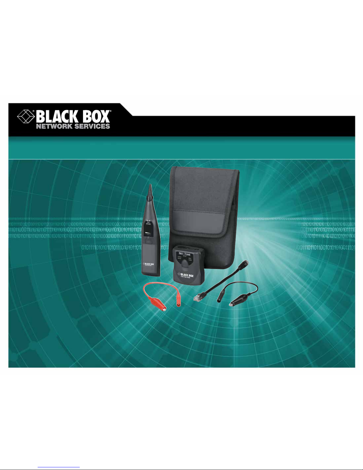
Easily identify hub or switch ports
within active networks.
Easily identify hub or switch ports
within active networks.
NetTone Network Tone and Probe
© 2007. All rights reserved. Black Box Corporation.
FREE 24-hour Tech Support: 724-746-5500
blackbox.com
Page 2

2 of 2
8/8/2007
#26813
724-746-5500 blackbox.com
FEA TURES
• The tone generator sends a trace tone,
and the probe detects the signal.
• Port ID function activates link light
on connected hub or switch to show
corresponding port link.
• Choose from three user-selectable
link pulse rates.
• Auto shutoff extends battery life.
• Includes alligator-clip test leads for
making quick punchdown block or
unterminated cable connections.
• Offers wide compatibility with
equipment from various manufacturers.
• Works on inactive circuits, too!
• Features RJ-45 male or female
connectors on tone generator.
• Detects short or open circuits.
• Works on Ethernet and telco cabling.
• Probe emits distinct audible tones and
features nonconductive plastic tip.
OVERVIEW
Here’s the essential cable- and port-identification kit for
network managers and technicians. The BLACK BOX
®
NetTone
Network Tone and Probe enables you trace cables and identify
network terminations in active networks effectively.
The kit includes a tone generator to transmit a trace tone
and a probe to detect a tone signal. It uses link light activation
to help you identify port assignments. Identifying a drop in an
active network is as simple as looking for a blinking light on a
hub or switch.
And because the tone generator emits distinct tone
frequencies and patterns, you can use it for traditional audible
toning of inactive circuits, too.
Designed for both Ethernet and telco circuits.
Ordinary tone and probe kits are usually hard-wired for telco
maintenance, not network maintenance, and can disrupt network
traffic if hooked to an active LAN circuit. What’s more, cable
twist and crosstalk as well as any audible tone bleed can make
it difficult to track down a termination point.
But the NetTone Network Tone and Probe is designed
for Ethernet connections as well as telco connections.
To trace an Ethernet connection, connect the NetTone tone
generator to an unterminated cable pair or punchdown block
with the included red and black test leads, or connect it to a
wall outlet with the patch cable (also included).
For telco connections, simply plug an RJ-11 patch cable into
the tone generator’s RJ-45 jack, and the tone transmits on Pairs 4
and 5.
Tone to identify port assignments.
To use the NetTone for port identification, connect the
tone generator to the wallplate, select the Port ID function, and
choose your trace tone blink rate for transmitted pulses. Then all
you have to do is locate the corresponding link pulse on the hub
or switch to determine which port goes to the wallplate. Three
selectable blink rates help ensure compatibility with Ethernet
hardware from various manufacturers.
Tone and probe to identify cable termination.
To trace cables, connect the NetTone tone generator to your
cable or outlet, select your tone pattern, and place the NetTone
probe near the cable pair or punchdown you want to identify.
The probe indicates detection by emitting an audible signal at
the same frequency you’ve selected for the tone generator. It’s
loudest when the probe is near the correct termination point.
Youcan even control the volume of the audible signal.
Perform short-circuit tests, too.
NetTone provides short-circuit tests on Pins 4 and 5 of the
RJ-45 jack. To test for short circuits, simply connect the tone
generator to a cable using the red and black test leads and
select the “Short“ function. An LED indicates whether a short
is detected.
Battery-powered with auto shutoff.
The NetTone’s tone generator and probe are 9-V batterypowered. The tone component features a low-battery indicator
and powers down automatically after about 20 minutes of
operation, extending battery life.
Item Code
NetTone Network Tone and Probe TS605A
✦
NetTone tone generator
✦
NetTone probe
✦
(2) alligator clip test leads (red and black)
✦
RJ-45–RJ-45 patch cable, 8.375" (21.3 cm)
✦
Carrying pouch
✦
User manual
WHA T‘S INCLUDED
TECH SPECS
Frequencies — Low tone: 1 kHz pulsed;
High tone: 8 kHz pulsed;
Reception frequencies: Broadband 100 Hz–10 kHz
Temperatur e —Operating: 32 to 122° F (0 to 50° C);
Storage: 14 to 131° F (-10 to +55°C)
Power — (1) 9-V battery for each component
Size — T one generator: 2.4"H x 3"W x 1.4"D (6.1 x 7.6 x 3.6 cm);
Probe: 8"H x 1.5"W x 1.4"D (20.3 x 3.8 x 3.6 cm)
 Loading...