

Page 1
1000 Park Drive • Lawrence, PA 15055-1018 • 724-746-5500 • Fax 724-746-0746
© Copyright 2004. Black Box Corporation. All rights reserved.
Page 2
JULY 2004
TS590A
TS591
TS592
TS593
SOHO Tester
CUSTOMER SUPPORT INFORMATION
Order toll-free in the U.S.: Call 877-877-BBOX (outside U.S. call 724-746-5500)
FREE technical support 24 hours a day, 7 days a week: Call 724-746-5500 or fax 724-746-0746
Mailing address: Black Box Corporation, 1000 Park Drive, Lawrence, PA 15055-1018
Web site: www.blackbox.com • E-mail: info@blackbox.com
Page 3

Page 4

1
FEDERAL COMMUNICATIONS COMMISSION
AND
INDUSTRY CANADA
RADIO FREQUENCY INTERFERENCE STATEMENTS
This equipment generates, uses, and can radiate radiofrequency energy, and if not installed and used properly, that
is, in strict accordance with the manufacturer’s instructions,
may cause interference to radio communication. It has been
tested and found to comply with the limits for a Class A
computing device in accordance with the specifications in
Subpart B of Part 15 of FCC rules, which are designed to
provide reasonable protection against such interference when
the equipment is operated in a commercial environment.
Operation of this equipment in a residential area is likely to
cause interference, in which case the user at his own expense
will be required to take whatever measures may be necessary
to correct the interference.
Changes or modifications not expressly approved by the party
responsible for compliance could void the user’s authority to
operate the equipment.
This digital apparatus does not exceed the Class A limits for radio
noise emission from digital apparatus set out in the Radio Interference
Regulation of Industry Canada.
FCC AND IC RFI STATEMENTS
Page 5

2
SOHO TESTER
Le présent appareil numérique n’émet pas de bruits radioélectriques
dépassant les limites applicables aux appareils numériques de classe
A prescrites dans le Règlement sur le brouillage radioélectrique publié
par Industrie Canada.
Page 6

3
NOM STATEMENT
NORMAS OFICIALES MEXICANAS (NOM)
ELECTRICAL SAFETY STATEMENT
INSTRUCCIONES DE SEGURIDAD
1. Todas las instrucciones de seguridad y operación
deberán ser leídas antes de que el aparato eléctrico sea
operado.
2. Las instrucciones de seguridad y operación deberán
ser guardadas para referencia futura.
3. Todas las advertencias en el aparato eléctrico y en sus
instrucciones de operación deben ser respetadas.
4. Todas las instrucciones de operación y uso deben ser
seguidas.
5. El aparato eléctrico no deberá ser usado cerca del
agua—por ejemplo, cerca de la tina de baño, lavabo,
sótano mojado o cerca de una alberca, etc..
6. El aparato eléctrico debe ser usado únicamente con
carritos o pedestales que sean recomendados por el
fabricante.
7. El aparato eléctrico debe ser montado a la pared o al
techo sólo como sea recomendado por el fabricante.
Page 7

4
SOHO TESTER
8. Servicio—El usuario no debe intentar dar servicio al
equipo eléctrico más allá a lo descrito en las
instrucciones de operación. Todo otro servicio deberá
ser referido a personal de servicio calificado.
9. El aparato eléctrico debe ser situado de tal manera
que su posición no interfiera su uso. La colocación del
aparato eléctrico sobre una cama, sofá, alfombra o
superficie similar puede bloquea la ventilación, no se
debe colocar en libreros o gabinetes que impidan el
flujo de aire por los orificios de ventilación.
10. El equipo eléctrico deber ser situado fuera del alcance
de fuentes de calor como radiadores, registros de
calor, estufas u otros aparatos (incluyendo
amplificadores) que producen calor.
11. El aparato eléctrico deberá ser connectado a una
fuente de poder sólo del tipo descrito en el instructivo
de operación, o como se indique en el aparato.
12. Precaución debe ser tomada de tal manera que la
tierra fisica y la polarización del equipo no sea
eliminada.
13. Los cables de la fuente de poder deben ser guiados de
tal manera que no sean pisados ni pellizcados por
objetos colocados sobre o contra ellos, poniendo
particular atención a los contactos y receptáculos
donde salen del aparato.
Page 8

5
NOM STATEMENT
14. El equipo eléctrico debe ser limpiado únicamente de
acuerdo a las recomendaciones del fabricante.
15. En caso de existir, una antena externa deberá ser
localizada lejos de las lineas de energia.
16. El cable de corriente deberá ser desconectado del
cuando el equipo no sea usado por un largo periodo
de tiempo.
17. Cuidado debe ser tomado de tal manera que objectos
liquidos no sean derramados sobre la cubierta u
orificios de ventilación.
18. Servicio por personal calificado deberá ser provisto
cuando:
A: El cable de poder o el contacto ha sido dañado; u
B: Objectos han caído o líquido ha sido derramado
dentro del aparato; o
C: El aparato ha sido expuesto a la lluvia; o
D: El aparato parece no operar normalmente o
muestra un cambio en su desempeño; o
E: El aparato ha sido tirado o su cubierta ha sido
dañada.
Page 9

6
SOHO TESTER
TRADEMARKS USED IN THIS MANUAL
Any trademarks mentioned in this manual are
acknowledged to be the property of the trademark
owners.
Page 10

7
CONTENTS
Contents
Chapter Page
1. Specifications . . . . . . . . . . . . . . . . . . 9
2. Introduction. . . . . . . . . . . . . . . . . . 11
2.1 Overview . . . . . . . . . . . . . . . . . 11
2.2 The SOHO Tester
Illustrated . . . . . . . . . . . . . . . . 13
3. Test Modes . . . . . . . . . . . . . . . . . . . 15
3.1 Telephone (TEL) Cable
Test Mode . . . . . . . . . . . . . . . . 15
3.2 Network (NTWK) Cable
Test Mode . . . . . . . . . . . . . . . . 17
3.3 Tone Mode . . . . . . . . . . . . . . . 19
3.4 Coax Mode . . . . . . . . . . . . . . . 20
3.5 Volts Mode. . . . . . . . . . . . . . . . 21
Page 11

8
SOHO TESTER
Contents (continued)
Chapter Page
4. Cable Testing . . . . . . . . . . . . . . . . . 23
4.1 To Test a Patch Cable. . . . . . . 23
4.2 To Test a Coax Cable . . . . . . . 24
4.3 To Place a Tone on a Cable . . 25
5. Interpreting Cable Test Results . . 27
6. Replacing the Battery . . . . . . . . . . 36
7. Troubleshooting . . . . . . . . . . . . . . 38
7.1 Calling Black Box . . . . . . . . . . 38
7.2 Shipping and Packaging. . . . . 39
Page 12

9
CHAPTER 1: Specifications
1. Specifications
Battery Life: 9V alkaline battery, typical;
Standby mode: 2.5 years;
Cable testing: 150 hours;
Tone generator: 250 hours
Cable Types: Shielded or unshielded,
CAT5e, CAT5, CAT4, CAT3, and coax
Minimum Cable Length for Testing of Split
Pairs: 3 ft. (0.9 m)
Coax Cable: 100 ohms maximum DC
resistance, center conductor plus shield
User Controls: (5) buttons: (1) TEL,
(1) COAX, (1) TONE, (1) NTWK,
(1) REMOTE UNIT
Page 13

10
SOHO TESTER
Connectors: (1) F-connector female,
(1) RJ-45 female, (1) 6-wire RJ-12 female
Indicators: (1) LCD display
Temperature Tolerance: Operating: 32 to
122°F (0 to 50°C); Storage: 14 to 140°F
(-10 to +60°C)
Relative Humidity: Up to 90%,
noncondensing
Power: (1) removable 9-volt battery
Size: 5.2"H x 2.9"W x 1.6"D (13.2 x 7.4 x
4.1 cm)
Weight (with battery and remote): 8.5 oz.
(241 g)
Page 14

11
2. Introduction
WARNING
Do not attach the tester to AC power. It
may be damaged and cause a safety
hazard.
CAUTION
Improperly crimped or damaged plugs can
damage the tester’s jacks. Inspect plugs
for proper termination and crimping before
inserting into the tester. Contacts should
always be recessed into the plug’s plastic
grooves. Do not use 6-position plugs with
the 8-position (network) jack.
2.1 Overview
The SOHO Tester is designed to test all
common low-voltage cabling systems found
in homes—telephone, network, or video.
The tester has a large, bright LCD display
and four buttons used to access each
function. The remote attaches to the main
unit for storage and patch cable testing.
CHAPTER 2: Introduction
Page 15

12
SOHO TESTER
The tester tests network (8-wire),
telephone (6-wire), and coax cabling
systems. It supports eight network remotes
and ten coax remotes.
Available in a 20-pack are Coax Remote
Identifiers (TS591), RJ-45 Wire Mappers
(TS592), or RJ-11 Wire Mappers (TS593).
The numbered coax identifiers and the
wire mappers attach to the coax or twistedpair cable’s end. To tell you which cables
are being tested, the label numbers on the
coax identifiers and wire mappers appear
on the tester’s LCD during the test.
The large, seven-segment LCD uses icons
for clear cable test results that are
displayed in wire map format. The tester
checks for shorts, opens, miswires, reverse
pairs (a type of miswire), and split pairs.
Page 16

13
CHAPTER 2: Introduction
For correctly wired straight-through or
crossover TS568A/B cables, the tester
displays the PASS icon. For correctly wired
straight-through or crossover 6-pin
telephone cables, the tester also displays
the PASS icon.
The tester features a tone generator mode
for use with tone tracers. It automatically
powers off in any mode and consumes low
power for long battery life.
A convenient modular plug remote and
coax test terminator store in the tester’s
case’s bottom end.
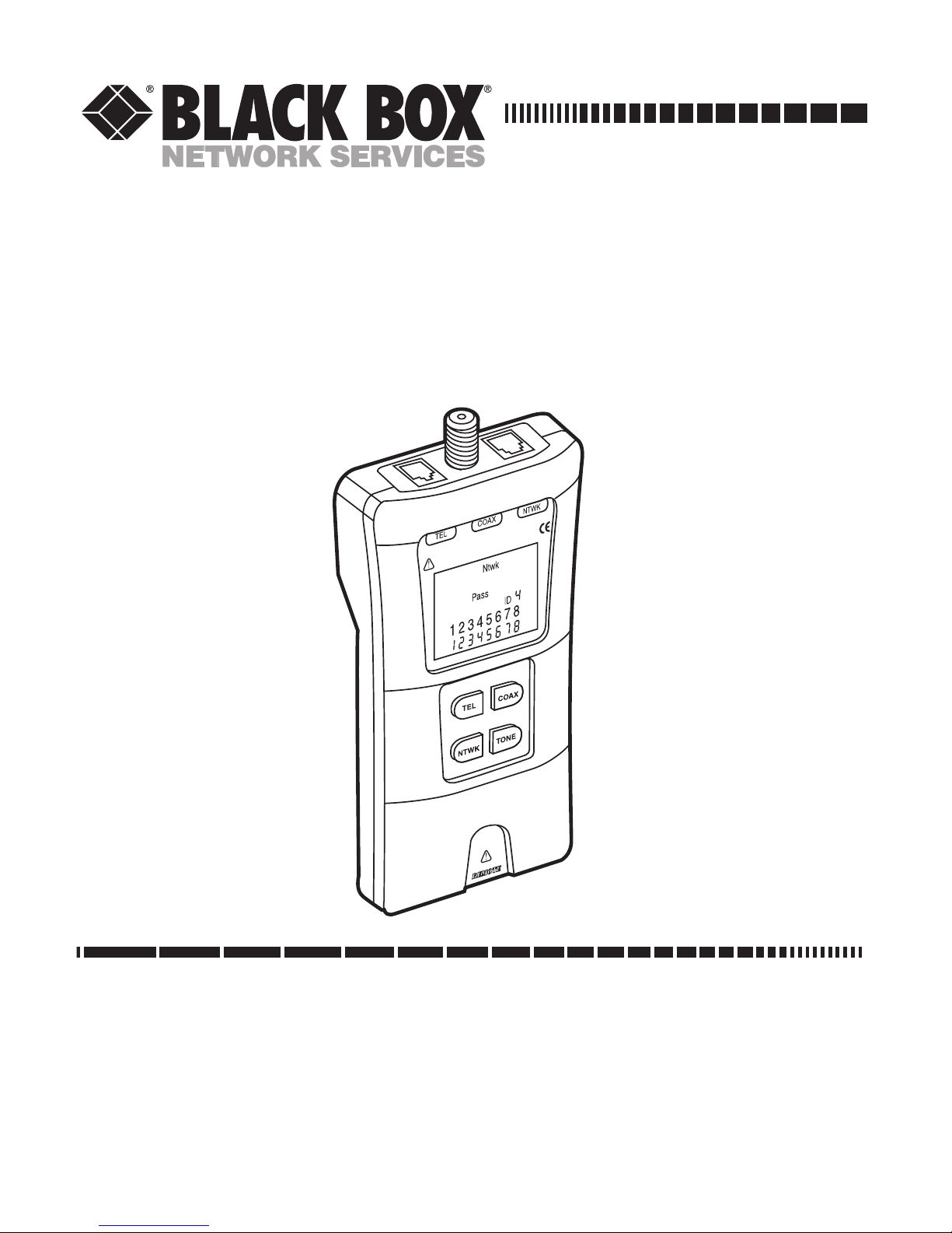
2.2 The SOHO Tester Illustrated
Figure 2-1 shows the SOHO tester.
Page 17
14
SOHO TESTER
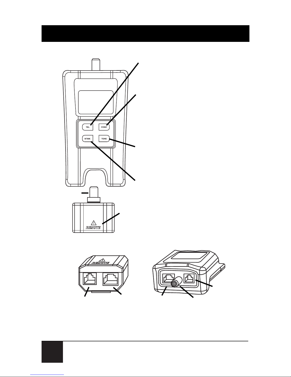
Figure 2-1. The SOHO tester’s buttons.
TEL (Telephone cable test): Press to power
on and begin testing. Uses 3-pair USOC
standard and 6-position RJ jack. Press for 2
seconds to turn off the split pair test.
COAX (Coax cable test): Press to power on
and begin testing. Tests for shorts, opens,
and identifies up to 10 unique remotes on the
F-connector jack. Use with the test terminator
stored in the back of the RJ remote on the
tester’s bottom.
TONE (Tone generator): Press a cable test
button for the connector being used, then
press the TONE button. Displays pins being
driven in that connector’s terms.
REMOTE UNIT: Squeeze the remote at the finger
grip openings in the main unit to remove it. Use the
same connector on the remote as on the main unit.
NTWK: (Network cable test): Press to
power on and begin testing. Uses T568A/B
standard and 8-position RJ jack.
Test terminator
Remote unit—front view
6-Position
8-Position
(shielded)
6-Position
8-Position
(shielded)
COAX
(F-connector)
Main unit—front view
Page 18

15
CHAPTER 3: Test Modes
3. Test Modes
3.1 Telephone (TEL) Cable Test Mode
The SOHO Tester assumes that the
6-position jack on the main unit and the
remote will be used for connecting the
tester to the cable run you want to test.
This mode uses the 3-pair USOC standard
to define the pairs. Connector pins 1–6,
2–5, and 3–4 are the pairs defined by this
standard. The tester will display the PASS
icon when all 6 pins are correctly wired in a
one-to-one order. If all 6 pins are correctly
wired in the reverse order, the PASS icon
and a flashing REV icon will appear.
Standard telephone cables used between a
phone set and a wall jack are usually
reverse-pinned.
Page 19

16
SOHO TESTER
After turning on the telephone cable test
mode, subsequently pressing the TEL
button for less than 2 seconds long forces a
new test cycle to begin immediately when
the button is released. Use this to begin a
new test when attaching a new cable to the
tester. Hold the button down for more
than 2 seconds to turn the split pair test
off. The SPLIT icon and the word OFF
appear on the screen momentarily to
indicate this. Another long press will toggle
back to the split pair testing, and so on.
When split pair testing is not required (as
in the testing of flat satin cable), turn off
the split pairs test. This way a cable may
pass based on continuity only.
Page 20

17
CHAPTER 3: Test Modes
3.2 Network (NTWK) Cable Test Mode
The SOHO Tester assumes the 8-position
jack on the main unit and the remote will
be used for connecting the tester to the
cable run to be tested. The TIA/EIA
568A/B standard is used to define the
pairs. Connector pins 1–2, 3–6, 4–5, and
7–8 are the pairs defined by this standard.
The A and B standards are the same except
for color-coding and are indistinguishable
from each other by electrical testing. The
tester will display the PASS icon when all 8
pins are correctly wired in a one-to-one
order. If all 8 pins are correctly wired with
the 1–2 and 3–6 pairs crossed, the PASS
icon will be displayed along with a flashing
UPLINK icon. Uplink cables are also
known as crossover or T568A-to-T568B
cables and are commonly used to connect
Page 21

18
SOHO TESTER
two computers or two hub/switches
directly together.
After turning on the network cable test
mode, press the NTWK button for less
than 2 seconds to force a new test cycle to
begin immediately upon releasing the
button. Use this to immediately begin a
new test when attaching a new cable to the
tester. Holding the NTWK button down
for more than 2 seconds turns the split pair
test off. The SPLIT icon and the word OFF
appear on the screen momentarily to
indicate this. Another long press will toggle
back to the split pair testing, and so on.
When split pair testing is not required (as
in the testing of flat satin cable), the split
pairs can be turned off. This way a cable
may pass based on continuity only.
Page 22

19
CHAPTER 3: Test Modes
3.3 Tone Mode
The tone mode generates audio tones for
use with tone tracers on all pairs, a selected
pair, or a selected pin.
The signal generated on a pair has the
signal on one pin and the complement of
the signal on the other pin of the pair. This
yields a nominal 10 volts peak-to-peak
across the pair.
A selected pin number or the letters P (for
pin) and S (for shield), along with the
currently selected tone pattern, are
displayed on the screen. The TONE icon
and the icon for the selected connector are
also displayed. Once in the tone generator
mode, when you press the TONE button
for less than 2 seconds, the tester goes on
to the next connector pin(s). When you
Page 23

20
SOHO TESTER
press the TONE button for longer than 2
seconds, you’ll get either dual or warble
tones of differing pattern duration.
Pressing any button other than the TONE
button turns off the SOHO Tester. The
tone signal will turn off automatically after
about 2 hours and 24 minutes.
3.4 Coax Mode
The SOHO Tester assumes that the coax
jack on the main unit and the remote will
be used for connecting the tester to the
coax cable run to be tested.
Press the COAX button to test the cable.
The tester will display the PASS icon when
the coax cable is correctly wired. The PASS
icon and a flashing UPLINK icon will
appear.
Page 24

21
CHAPTER 3: Test Modes
3.5 Volts Mode
The SOHO Tester monitors voltages
present on the jacks during each test cycle.
This test is automatically executed when
the cable is connected; you don’t need to
press a button. If voltage is found, the
VOLTS icon is displayed and testing stops
until the voltage is removed.
Figure 3-1 shows the tester’s available
parameters that appear on its LCD
display.
Page 25

22
SOHO TESTER
Figure 3-1. The SOHO Tester’s LCD testing options.
NOTE
The SOHO Tester powers off automatically 9 minutes after the last button is
pressed in cable testing modes and after
approximately 2 hours and 24 minutes in
tone mode. If you’re using the tester for
the first time, install a battery.
Mode icons
Voltage Detected
warning
Pass and Fail
icons
Main unit pin
numbers
Remote pin
numbers
Special cable icons
Battery low
Remote ID
number
Shield connected
Page 26

23
CHAPTER 4: Cable Testing
4. Cable Testing
4.1 To Test a Patch Cable
1. Plug one end of the patch cable into
the main unit.
2. Plug the other end of the cable into
the remote unit.
3. Press TEL or NTWK as appropriate
for the jack the patch cable is
connected to. The SOHO Tester will
power on and begin testing. If the
tester was already on, press TEL or
NTWK to initiate a new test. Results
are invalid if a cable is attached
during a test in progress.
4. To turn the tester off, press the
COAX button.
Page 27

24
SOHO TESTER
4.2 To Test a Coax Cable
1. Attach one end of the coax cable to
be tested to the F-connector on the
main unit.
2. The remote unit is installed in an
opening at the bottom of the main
unit. Remove the remote unit from
the main unit by squeezing the
remote lightly between your thumb
and forefinger and pulling it out.
Remove the coax identifier (which is
installed in a storage pocket on the
back of the remote) and attach it to
the other end of the cable to be
tested.
3. Press the COAX button to power on
the unit and begin testing. The
results are updated about once a
second.
Page 28

25
CHAPTER 4: Cable Testing
4. To turn the SOHO Tester off, press
either the TEL or NTWK button.
4.3 To Place a Tone on a Cable
1. Connect the cable to be traced to a
main unit jack. For the best signal, do
not connect a remote to the other
end. Due to the shielding effect of
twisted pairs, the strongest signal is
obtained by having one wire of a pair
carry tone. Selecting a single pin
instead of a pair will do this. For
coax, tone is best applied to the
shield and the shield cannot be
grounded.
2. Power on the tester by pressing the
button associated with the connector
to be used (for example, press TEL
or COAX), then press the TONE
button. Briefly pressing the TONE
Page 29

26
SOHO TESTER
button will select a different pin.
Holding down the TONE button for
more than 2 seconds will select a
different tone pattern.
3. To power off the tester, press any
button except TONE. The tone
signal will turn off automatically after
about 2 hours and 24 minutes.
Page 30

27
CHAPTER 5: Interpreting Cable Test Results
5. Interpreting Cable Test
Results
The PASS icon will be on if the cable has
all pins properly connected per T568A/B
for network cables or per 3-pair USOC for
telephone cables. The FAIL, SHORT,
OPEN, or SPLIT icon will be on if there is
a wiring error. The wire map will display
the end-to-end connections measured
whenever possible.
The PASS icon (see Figure 5-1) will also be
on with a flashing UPLINK icon if a
network cable has the 1–2 and 3–6 pairs
transposed. This indicates a properly wired
uplink (crossover) cable. In telephone
mode, the REV icon will flash if all
connected pins are in reverse order.
The PASS icon will also be on if all 6
Page 31

28
SOHO TESTER
connections are present. Telephone
modular plug cables used between the wall
jack and a phone set are usually reverse
pinned.
Figure 5-1. T568A/B wiring diagram (shown at left)
and the tester’s LCD display (shown at right)
for a passing cable.
PASS icon
Page 32

29
CHAPTER 5: Interpreting Cable Test Results
The four classes of faults discussed next are
in order of severity (higher to lower). The
severity has to do with the ability of a more
severe error to mask less severe errors. For
example, if there is a short in the cable,
miswires and split pairs may not be
detected for the pairs involved in the short
fault.
S
HORT
The pair has a low-resistance connection
from one wire of the pair to the other wire
of the pair or to any other wire in the cable
or the shield. A short is indicated by the
SHORT icon being on and flashing S in
the appropriate pin positions on the
second line. See Figure 5-2.
Page 33

30
SOHO TESTER
Figure 5-2. Wiring diagram (shown at left) and the
tester’s LCD display (shown at right) for a short.
M
ISWIRE
When a miswire exists, a wire or both wires
of a pair are not connected to the correct
pins at the cable’s other end. The wire
map shows the pin numbers from line 1
(main) to line 2 (remote). A reverse pair is
a special case of a miswire where the pair is
wired to the correct pair of pins or to
SHORT icon
Page 34

31
CHAPTER 5: Interpreting Cable Test Results
another designated pair of pins, but the
two leads are reversed. The SOHO Tester
is able to test for miswires as long as the
wiring errors are in pairs. The FAIL icon
and the pin numbers, which are miswired,
will be flashing. See Figure 5-3.
Figure 5-3. Wiring diagram (shown at left) and the
tester’s LCD display (shown at right) for a miswire.
FAIL icon
Page 35

32
SOHO TESTER
S
PLITPAIR
A split pair is an error in the twisting of the
wires together within the cable. The cables
are generally made up of eight wires
twisted together in four pairs. These four
pairs are designated as pairs by the wiring
standards and are intended to carry a
signal and its return. 1&2, 3&6, 4&5, and
7&8 are the pairs designated by T568A/B
for an RJ-45 jack or plug. A cable can be
wired with correct continuity but not with
correct pairing. This most often happens
when the cable is terminated consistently
at both ends, but in the wrong order. If the
only error is a split pair error, the cable has
correct continuity. If crosstalk is not a
concern (as in flat satin cable), the cable is
good if the only error is the split pair error.
The SPLIT icon and the pin numbers on
Page 36

33
CHAPTER 5: Interpreting Cable Test Results
the first and second line of the wire map
with split pairs flash when there is a split
pair error. See Figure 5-4.
The SOHO Tester has the ability to turn
off the split pair error testing. Pressing the
button for the current cable test mode
more than two seconds turns off the split
pair testing. The SPLIT icon and the word
OFF appear on the screen momentarily to
indicate this. The split pair testing will
resume the next time the tester is turned
on, or it may be toggled back on by
another two-second press of the current
test mode button.
Page 37

34
SOHO TESTER
Figure 5-4. Wiring diagram (shown at left) and the
tester’s LCD display (shown at right) for a split pair.
O
PEN
When an OPEN exists, some conductors in
the cable you’re testing aren’t terminated.
The pin numbers of the unterminated
conductors will flash on the tester’s LCD
display. See Figure 5-5.
SPLIT icon
Page 38

35
CHAPTER 5: Interpreting Cable Test Results
Figure 5-5. Wiring diagram (shown at left) and the
tester’s LCD display (shown at right) for an open.
OPEN icon
Page 39

36
SOHO TESTER
6. Replacing the Battery
When the BATTERY icon is on, the battery
should be replaced as soon as is practical.
The cable test results become unreliable
when the battery reaches approximately
4.5 volts. Follow the steps below to replace
the battery.
1. Use a Phillips screwdriver to remove
the screw from the battery door on
the back of the unit.
2. Pull the battery out of the cavity and
remove the battery snap.
3. Connect a new 9-volt alkaline battery
to the battery snaps. Place the battery
back into the tester’s body with the
battery snaps at the front end of the
compartment.
Page 40

37
CHAPTER 6: Replacing the Battery
4. Replace the battery door and screw,
being careful not to overtighten the
screw.
Page 41

38
SOHO TESTER
7. Troubleshooting
7.1 Calling Black Box
If you determine that your SOHO Tester is
malfunctioning, do not attempt to alter or
repair the unit. It contains no userserviceable parts. Contact Black Box at 724746-5500.
Before you do, make a record of the
history of the problem. We will be able to
provide more efficient and accurate
assistance if you have a complete
description, including:
• the nature and duration of the
problem.
• when the problem occurs.
Page 42

39
CHAPTER 7: Troubleshooting
• the components involved in the
problem.
• any particular application that, when
used, appears to create the problem
or make it worse.
7.2 Shipping and Packaging
If you need to transport or ship your
SOHO Tester:
• Package it carefully. We recommend
that you use the original container.
• If you are shipping the SOHO Tester
for repair, make sure you include
everything that came in the original
package. Before you ship, contact
Black Box to get a Return
Authorization (RA) number.
 Loading...