

Page 1

Overview and Installation
The Fiber Optic Splitter Module monitors network traffic flowing in either direction on a fiberoptic network
(Ethernet, Fast Ethernet, FDDI, ATM, and SONET) at data rates up to OC3 (155 Mbps). It has four ports. Data
Ports A and B are each dual SC female 62.5/125-µm multimode fiberoptic connectors that can be attached to
fiberoptic network devices (NICs, switches, routers, etc.). Analyzer Ports A and B are both carried on one dual
SC female 62.5/125-µm multimode fiberoptic connector that can be attached to a LAN analyzer.
The splitter module is light, compact, and portable. You can also mount as many as three modules in a 19"
equipment rack with our 3-Module Rackmount Kit (RM210; cover any open slots in the kit with Filler Blanks
[RM211]). Run standard 62.5/125-µm multimode fiberoptic cable (with SC connectors on the module end)
from the splitter module to the other devices. For the connection to the LAN analyzer, we recommend a Fiber
Optic Analyzer Patch Cable (EFN4029-CT), shown below.
Figure 1. The Fiber Optic Analyzer Patch Cable (EFN4029-CT).
FEBRUARY 2006
TS220A-R2
Fiber Optic Splitter Module
Fiber Optic
Splitter
Module
Order toll-free in the U.S.: Call 877-877-BBOX (outside U.S. call 724-746-5500)
FREE technical support 24 hours a day, 7 days a week: Call 724-746-5500 or fax 724-746-0746
Mailing address: Black Box Corporation, 1000 Park Drive, Lawrence, PA 15055-1018
Web site: www.blackbox.com • E-mail: info@blackbox.com
CUSTOMER
SUPPORT
INFORMATION
LAN analyzer
(or monitoring
device)
MULTIMODE
DUPLEX SC CONNECTOR
Rx
Rx
Tx
Rx
Tx
Rx
3-foot (0.9-m) 6.25/125-µm SC/SC patch cord
Page 2
Operation
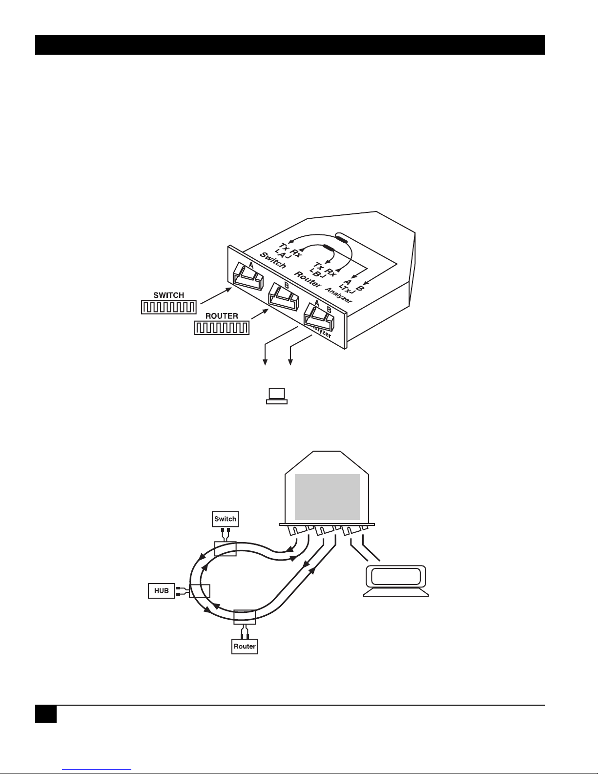
Once you’ve connected the other devices to the Fiber Optic Splitter Module, it will begin operating immediately.
(It’s a passive device and doesn’t need to draw power from anywhere.) The splitter module can operate in either
full or half-duplex mode. It taps the incoming data on either or both strands of your network’s fiberoptic lines and
sends 20% of the signal to the analyzer ports for performance evaluation and error detection (see Figures 2 and 3).
The tapped data is fed to the analyzer ports at network speed (up to OC3, 155 Mbps) and at normal signal levels.
Signal integrity is guaranteed for the lines (the tapping will not affect either the signal integrity or loading factor);
the splitter module regenerates incoming data from the network lines before retransmitting it.
Figure 2. Attaching devices to the splitter module (internal data flow also shown).
Figure 3. Total data flow when used in a ring network.
FIBER OPTIC SPLITTER MODULE
2
Fiber Optic
Splitter
Module
20% signal
LAN analyzer
(monitoring software programs)
80% signal
LAN network
traffic
Tx
LAN analyzer
(or monitoring device)
Page 3

FIBER OPTIC SPLITTER MODULE
3
Specifications
Compliance: CE
Compatibility: LAN: 10BASE-FL Ethernet, 100BASE-FX Fast Ethernet, FDDI, ATM, and
SONET;
Optical wavelength: 850 and 1300 nm
Signal-Split Ratio: 80% to data ports, 20% to analyzer ports
Internal Loss Due to
Signal Splitting: Data ports: ≤ 2.2 dB;
Analyzer ports: ≤ 7 dB
Cable-Insertion Loss: ≤ 0.35 dB
Polarization-Dependent
Loss: ≤ 0.1 dB
MTBF: Device is solid state; internal components should never spontaneously fail
Enclosure: 16-gauge cold-rolled steel
Interface: 6.5/125-µm multimode fiberoptic
Connectors: (2) Dual (“duplex”) SC female for network connections;
(1) Dual SC female for monitoring connection (but the two sides of this
connector function as two independent ports)
Indicators: None
Temperature Tolerance: Operating: -40 to +176˚F (-40 to +80˚C);
Storage: -40 to +185˚F (-40 to +85˚C)
Humidity Tolerance: Up to 85% noncondensing
Size: 1.2"H x 4.5"W x 5"D (3 x 11.4 x 12.7 cm)
Weight: 0.5 lb. (0.2 kg)
BLACK BOX and the Double Diamond logo are registered trademarks of BB Technologies, Inc.
© Copyright 2006. Black Box Corporation. All rights reserved.
 Loading...