

Page 1
Get bidirectional buffers on each port
and make your network more efficient.
Get bidirectional buffers on each port
and make your network more efficient.
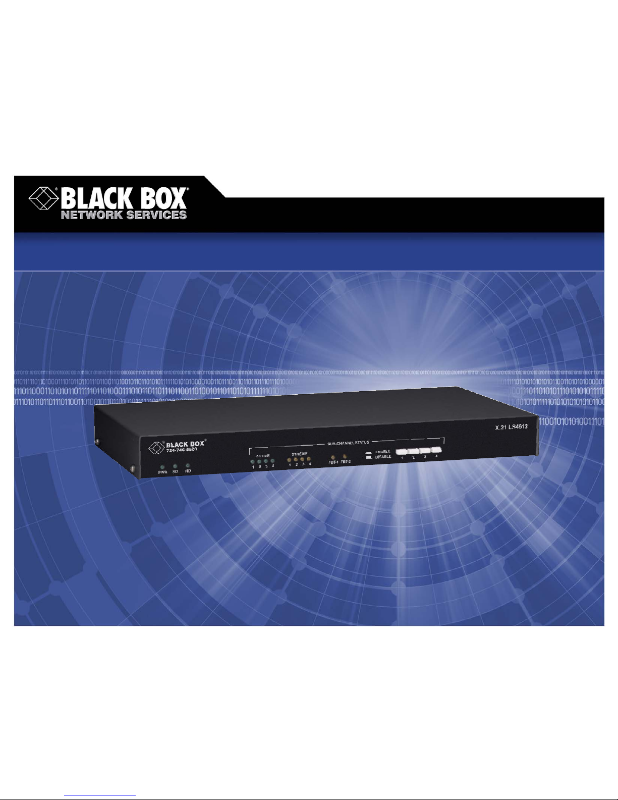
X.21 LS Buffers
© 2007. All rights reserved. Black Box Corporation.
FREE 24-hour Tech Support: 724-746-5500
blackbox.com
Page 2
2 of 3
FEATURES
• Up to four DTEs or DCEs per link. Share
the same port, in any combination.
• Compensate for systems having
different clock sources, syncing data
and control-character transmission.
• Ideal for synchronous network
environments.
• Individual subchannels enable and
disable switches.
• Anti-streaming automatically removes
a defective terminal from service.
OVERVIEW
So you want a cost-effective way to expand your existing
leased-line polled network without adding computers or
communication links?
Sure, others offer high-speed modem and port-sharing tools,
but they probably don’t support bidirectional buffering on each
port. To get that, you might have to buy additional tail-circuit
buffers. Do you really want that many boxes in your data
stream?
The simple, affordable solution is the X.21 LS Buffer.
Up to four DTE or DCE devices can share the same port, in
any combination, using the contention and control protocols
normally found in host hardware and software. The ports are
DTE/DCE selectable and meet the ITU X.21 standard, so you can
be assured of synchronous operation in the network by both
data terminal and data circuit equipment.
Once installed, the buffer boosts the efficiency of your system
and network by drawing upon the host processor‘s power and
reducing the idle time associated with many host-terminal traffic
sessions. The buffer temporarily stores information sent and
received between multiple devices with different data-handling
speeds and abilities. It then releases the data at slower speeds.
Ideal for synchronous network environments, the X.21 LS
is protocol-transparent at data rates up to 1.024 Mbps. Data
arrives at the master port and is continually broadcast to all
subchannels.
The 512-bit buffer also clocks data between different
network carriers, synchronizing the transmission of data and
control characters. This adjustable capacity and data clocking
make it an ideal choice for VSAT or land-line applications. It
reclocks data when the clock rate is at the same rate, but it
won’t lock onto the frequency of the different network carriers,
so no external tail-circuit buffers are needed. This elastic tailcircuit buffer compensates for different clock sources. Clocking
may be accomplished from any port of the unit, and two modes
are available for fallback clocking.
In applications where both the master port and the selected
port provide their own clocks, data is clocked into the buffer at
the receive rate of the active port and clocked out using the
master port transmit clock.
What’s more, the 4-port buffers feature a Channel 4-only
mode, which forces Port 4 as the active port to the master port.
Data and clock are then rebroadcast out to Ports 1–3 after
passing through the master port.
And, unlike most other sharing devices, the buffer can
be adjusted as your network changes. Using FieldProgrammable Gate Array (FPGA) technology, you’re able
to reprogram the buffer when sharing devices are added,
so the X.21 LS can, therefore, grow with your network
without needing new hardware. Your investment is
protected.
The X.21 LS is housed in a sturdy rackmount metal
enclosure and is equipped with a 110/220-VAC switchselectable linear power supply.
2/9/2007
#21456
724-746-5500 blackbox.com
The X.21 LS Buffer also features the following functions:
Automatic Removal—The buffer contains circuitry that,
when enabled, will automatically remove a streaming DCE
or DTE from service.
Each channel has a green and yellow LED to indicate
subchannel activity. If a terminal goes into the streaming
condition (Control continually high), the DTE will automatically be removed from service until you correct the
DTE fault. All other DTEs will continue to be serviced.
Upon installation, you can set or fine-tune the timer
to your network requirements.
Internal Clock Selection —The device also provides circuitry
that allows you to select internal clocks. Though the X.21 LS is
externally timed by the telco provider, the internal clock rates
are very useful for testing and diagnostic purposes.
Subchannel Scanning—This allows equal access to the
communications link for all connected DCE or DTE devices.
The subchannels are scanned in sequence, and the attached
subchannel that raises Control (C) or Indicate (I) will have
access to the communications link. After the subchannel drops
(C) or (I), the buffer will continue scanning in sequential order.
Technically Speaking
Page 3

3 of 3
2/9/2007
#21456
Recognize any of these situations?
• You wait more than 30 minutes to get through
to a vendor’s tech support.
• The so-called “tech” can’t help you or gives you
the wrong answer.
• You don’t have a purchase order number and the
tech refuses to help you.
• It’s 9 p. m. and you need help, but your vendor’s
tech support line is closed.
According to a survey by Data Communications
magazine, 90% of network managers surveyed say
that getting the technical support they need is extremely
important when choosing a vendor. But even though
network managers pay anywhere from 10 to 20% of their
overall purchase price for a basic service and support
contract, the technical support and service they receive falls
far short of their expectations— and certainly isn’t worth
what they paid.
At Black Box, we guarantee the best value and the
best support. You can even consult our Technical Support
Experts before you buy if you need help selecting just
the right component for your application.
Don’t waste time and money— call Black Box today.
Why Buy From Black Box?
Exceptional Value. Exceptional
Tech Support. Period.
724-746-5500 blackbox.com
Item Code
X.21 LS
512-Bit Buffer 4-Port TL572A
2-Port TL573A
8-Bit Buffer 4-Port TL574A
You may also need…
DB15 Cable with EMI/RFI Protection, Male to Male
6-ft. (1.8-m) EGM15E-0006-MM
10-ft. (3-m) EGM15E-0010-MM
20-ft. (6.1-m) EGM15E-0020-MM
TECH SPECS
Anti-Streaming — Automatic, selectable timeout intervals; Disable,
selectable via DIP switch
Capacity —
TL572A, TL574A: One to four ITU X.21 devices;
TL573A: One to two ITU X.21 devices
Clock Source — From Composite (master) port or subchannel Port 1
Data Format — Transparent at all data rates
Data Rate — Up to 1.024 Mbps
Flow Control — Indicate and Control leads
Memory —
TL572A–TL573A: Buffer up to 512 bits, First-In, First-Out (FIFO)
principle with automatic re-centering;
TL574A: Buffer up to 8 bits, FIFO principle with automatic re-centering
User Controls — Switches to enable/disable each channel
Interface — ITU X.21, V.11 using DB15 female connectors
Connectors —
Subchannel ports: TL572A, TL574A: (4) DB15 female;
TL573A: (2) DB15 female
Master ports: (1) DB15 female
Indicators — Front panel: Power, Send/Receive Data, Channel Active,
Channel Stream, FBT-1, FBT-2
Environmental — Operating Temperature: 32 to 122°F (0 to 50°C);
Humidity: 5 to 95% relative (noncondensing);
Maximum Altitude: 10,000 ft. (3048 m)
Power — 100–120 or 200–220 VAC, 50/60 Hz, internal, switch-selectable
Size — 4-port models: 1.8"H x 17"W x 9"D (4.6 x 43.2 x 22.9 cm);
2-port model: 1.7"H x 9"W x 9"D (4.3 x 22.9 x 22.9 cm)
Weight — 4-port models: 4.5 lb (2 kg);
2-port model: 3 lb (1.4 kg)
TL572A
 Loading...