

Page 1
JULY 1997
MC124A
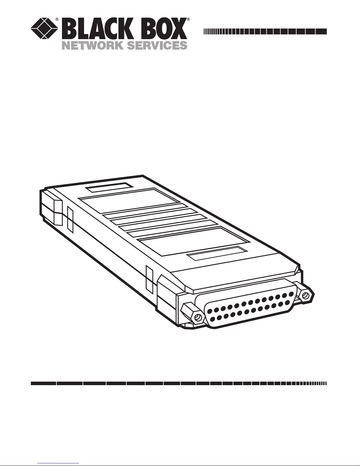
Tail-Circuit Adapter (TCA-232)
CUSTOMER SUPPORT INFORMATION
Order toll-free in the U.S. 24 hours, 7 A.M. Monday to midnight Friday: 877-877-BBOX
FREE technical support, 24 hours a day, 7 days a week: Call 724-746-5500 or fax 724-746-0746
Mail order: Black Box Corporation, 1000 Park Drive, Lawrence, PA 15055-1018
Web site: www.blackbox.com • E-mail: info@blackbox.com
Page 2

3
TCA-232
TRADEMARKS
All applied-for and registered trademarks are the
property of their respective owners.
Page 3

4
TCA-232
CONTENTS
1. Specifications . . . . . . . . . . . . . . . . . . . . . . . .5
2. Introduction . . . . . . . . . . . . . . . . . . . . . . . .6
2.1 Description . . . . . . . . . . . . . . . . . . . . .6
2.2 Features . . . . . . . . . . . . . . . . . . . . . . . .6
3. Installation . . . . . . . . . . . . . . . . . . . . . . . . . .7
4. Application . . . . . . . . . . . . . . . . . . . . . . . . .8
Page 4

5
TCA-232
1. Specifications
Transmission Format — Synchronous, transparent
to protocol
Data Rate — Up to 256 Kbps
Tail-to-System Buffering — 16-bit buffer, automatic
centering
Connectors — (2) DB25 female
DCE to DTE Connection — The TCA-232 provides
cross-pinning function
Temperature — 32 to 140°F (0 to 60°C)
Humidity — Up to 95%, noncondensing
Power — No AC power required; uses ultra-low
power derived from the EIA RS-232C, CCITT V.24
data and clock signals
Size — 1.2"H x 2"W x 5.3"D (3 x 5 x 13.5 cm)
Weight — 0.22 lb. (0.1 kg)
Page 5

6
TCA-232
2. Introduction
2.1 Description
The Tail-Circuit Adapter (TCA-232) has a 16-bit
buffer that helps you synchronize clock signals in
your tail circuit.
Data is transferred from the multiplexor directly
to the adjacent modem, using the mux receive clock
(pin 17), which is also provided to the modem
external clock (pin 24). Data received from the
remote terminal is loaded into the buffer using
the mux transmit clock (pin 15).
Since the TCA-232 performs all necessary cross
connections between the two DCEs, you only need
straight-through cables.
2.2 Features
• DCE to DCE connection
• Built-in buffer to prevent jitter errors
• Data rates up to 256 Kbps
• No strapping, easy to install
• No AC power required
• Compact and lightweight
Page 6

7
TCA-232
3. Installation
1. Connect the side of the TCA-232 labeled
“SYSTEM, J1” to the multiplexor sub-channel
or the main modem.
2. Connect the side of the TCA-232 labeled
“TAIL, J2” to the local modem. The local
modem should be strapped to external clock.
NOTE
The remote modem on the tail circuit should be strapped for
CLOCK LOOPBACK.
Page 7

8
TCA-232
4. Application
The TCA-232 is used to couple two DCE devices
together whose clocks are of the same frequency
but are not “in phase.”
An example is an extension of a multiplexor
channel using modems in a “tail circuit” (see
Figure 4-1). When the distance between the two
tail modems is significant, there is a difference in
phase between the multiplexor’s transmit clock
and the adjacent modem’s receive clock, resulting
in transmission errors. The TCA-232 acts as a buffer
between the DCEs to prevent these transmission
errors.
Page 8

9
TCA-232
Figure 4-1. Typical Application.
Mux
TCA
Terminal
Modem
(External
Clock)
Modem
(Clock
Loopback)
Page 9

10
TCA-232
Figure 4-2. Schematic Diagram of Data Flow.
BUFFER
TCA
SYSTEM
J1
TAIL
J2
15
TC 15
2
TD 2
4
RTS 4
17
RC 17
3
RD 3
8
DCD 8
6
DSR 6
20
DTR 20
5
CTS 5
1
PG 1
7
SG 7
17 RC
3RD
8 DCD
15 TC
2TD
4 RTS
20 DTR
6 DSR
1PG
7SG
17
3
8
15
2
4
20
6
1
7
24 ECLK
24
5 CTS
5
EXTERNAL
CLOCK
DCD
MUX
DCE
MODEM
Page 10

1000 Park Drive • Lawrence, PA 15055-1018 • 724-746-5500 • Fax 724-746-0746
© Copyright 1997. Black Box Corporation. All rights reserved.
 Loading...