

Page 1
CUSTOMER
SUPPORT
INFORMATION
Order toll-free in the U.S.: Call 877-877-BBOX (outside U.S. call 724-746-5500)
FREE technical support 24 hours a day, 7 days a week: Call 724-746-5500 or fax 724-746-0746
Mailing address: Black Box Corporation, 1000 Park Drive, Lawrence, PA 15055-1018
Web site: www.blackbox.com • E-mail: info@blackbox.com
JULY 2001
TC100A
Conference 1 Phone
Page 2

1
FCC/IC RFI STATEMENTS
FEDERAL COMMUNICATIONS COMMISSION AND INDUSTRY CANADA
RADIO-FREQUENCY INTERFERENCE STATEMENTS
Class B Digital Device. This equipment has been tested and found to comply with the
limits for a Class B computing device pursuant to Part 15 of the FCC Rules. These
limits are designed to provide reasonable protection against harmful interference
in a residential installation. However, there is no guarantee that interference will
not occur in a particular installation. This equipment generates, uses, and can
radiate radio-frequency energy, and, if not installed and used in accordance with
the instructions, may cause harmful interference to radio communications. If this
equipment does cause harmful interference to radio or telephone reception,
which can be determined by turning the equipment off and on, the user is
encouraged to try to correct the interference by one of the following measures:
• Reorient or relocate the receiving antenna.
• Increase the separation between the equipment and receiver.
• Connect the equipment into an outlet on a circuit different from that to which
the receiver is connected.
• Consult an experienced radio/TV technician for help.
Caution:
Changes or modifications not expressly approved by the party
responsible for compliance could void the user’s authority to operate
the equipment.
To meet FCC requirements, shielded cables and power cords are required to
connect this device to a personal computer or other Class B certified device.
This digital apparatus does not exceed the Class A limits for radio noise emission from
digital apparatus set out in the Radio Interference Regulation of Industry Canada.
Le présent appareil numérique n’émet pas de bruits radioélectriques dépassant les limites
applicables aux appareils numériques de la classe A prescrites dans le Règlement sur le
brouillage radioélectrique publié par Industrie Canada.
Page 3

2
CONFERENCE 1 PHONE
FEDERAL COMMUNICATIONS COMMISSION MODEM STATEMENT
1. The Federal Communications Commission (FCC) has established rules which
permit this device to be directly connected to the telephone network with
standardized jacks. This equipment should not be used on party lines or coin
lines.
2. If this device is malfunctioning, it may also be causing harm to the telephone
network; this device should be disconnected until the source of the problem
can be determined and until the repair has been made. If this is not done, the
telephone company may temporarily disconnect service.
3. If you have problems with your telephone equipment after installing this
device, disconnect this device from the line to see if it is causing the problem.
If it is, contact your supplier or an authorized agent.
4. The telephone company may make changes in its technical operations and
procedures. If any such changes affect the compatibility or use of this device,
the telephone company is required to give adequate notice of the changes.
5. If the telephone company requests information on what equipment is
connected to their lines, inform them of:
a. The telephone number that this unit is connected to.
b. The ringer equivalence number.
c. The USOC jack required: RJ-11C.
d. The FCC registration number.
Items (b) and (d) can be found on the unit’s FCC label. The ringer
equivalence number (REN) is used to determine how many devices can be
connected to your telephone line. In most areas, the sum of the RENs of all
devices on any one line should not exceed five (5.0). If too many devices are
attached, they may not ring properly.
6. In the event of an equipment malfunction, all repairs should be performed by
your supplier or an authorized agent. It is the responsibility of users requiring
service to report the need for service to the supplier or to an authorized
agent.
Page 4

3
MODEM STATEMENTS
INDUSTRY CANADA MODEM STATEMENT
The Industry Canada (IC) label identifies certified equipment. This certification
means that the equipment meets certain telecommunications-network protective,
operation, and safety requirements. Industry Canada does not guarantee the
equipment will operate to the user’s satisfaction.
Before installing this equipment, users should ensure that it is permissible to be
connected to the facilities of the local telecommunications company. The
equipment must also be installed using an acceptable method of connection. In
some cases, the company’s inside wiring associated with a single-line individual
service may be extended by means of a certified connector assembly (extension
cord). The customer should be aware that compliance with the above conditions
may not prevent degradation of service in some situations.
Repairs to certified equipment should be made by an authorized Canadian
maintenance facility—in this case, Black Box. Any repairs or alterations made by
the user to this equipment, or equipment malfunctions, may give the
telecommunications company cause to request the user to disconnect the
equipment.
Users should ensure for their own protection that the electrical ground
connections of the power utility, telephone lines, and internal metallic water pipe
system, if present, are connected together. This precaution may be particularly
important in rural areas.
CAUTION:
Users should not attempt to make such connections themselves, but
should contact the appropriate electric inspection authority, or
electrician, as appropriate.
The LOAD NUMBER (LN) assigned to each terminal device denotes the
percentage of the total load to be connected to a telephone loop which is used by
the device, to prevent overloading. The termination on a loop may consist of any
combination of devices, subject only to the requirement that the total of the load
numbers of all the devices does not exceed 100.
Page 5

4
CONFERENCE 1 PHONE
NORMAS OFICIALES MEXICANAS (NOM)
ELECTRICAL SAFETY STATEMENT
INSTRUCCIONES DE SEGURIDAD
1. Todas las instrucciones de seguridad y operación deberán ser leídas antes de
que el aparato eléctrico sea operado.
2. Las instrucciones de seguridad y operación deberán ser guardadas para
referencia futura.
3. Todas las advertencias en el aparato eléctrico y en sus instrucciones de
operación deben ser respetadas.
4. Todas las instrucciones de operación y uso deben ser seguidas.
5. El aparato eléctrico no deberá ser usado cerca del agua—por ejemplo, cerca
de la tina de baño, lavabo, sótano mojado o cerca de una alberca, etc..
6. El aparato eléctrico debe ser usado únicamente con carritos o pedestales que
sean recomendados por el fabricante.
7. El aparato eléctrico debe ser montado a la pared o al techo sólo como sea
recomendado por el fabricante.
8. Servicio—El usuario no debe intentar dar servicio al equipo eléctrico más allá
a lo descrito en las instrucciones de operación. Todo otro servicio deberá ser
referido a personal de servicio calificado.
9. El aparato eléctrico debe ser situado de tal manera que su posición no
interfiera su uso. La colocación del aparato eléctrico sobre una cama, sofá,
alfombra o superficie similar puede bloquea la ventilación, no se debe colocar
en libreros o gabinetes que impidan el flujo de aire por los orificios de
ventilación.
10. El equipo eléctrico deber ser situado fuera del alcance de fuentes de calor
como radiadores, registros de calor, estufas u otros aparatos (incluyendo
amplificadores) que producen calor.
11. El aparato eléctrico deberá ser connectado a una fuente de poder sólo del
tipo descrito en el instructivo de operación, o como se indique en el aparato.
Page 6

5
NOM STATEMENT
12. Precaución debe ser tomada de tal manera que la tierra fisica y la polarización
del equipo no sea eliminada.
13. Los cables de la fuente de poder deben ser guiados de tal manera que no
sean pisados ni pellizcados por objetos colocados sobre o contra ellos,
poniendo particular atención a los contactos y receptáculos donde salen del
aparato.
14. El equipo eléctrico debe ser limpiado únicamente de acuerdo a las
recomendaciones del fabricante.
15. En caso de existir, una antena externa deberá ser localizada lejos de las lineas
de energia.
16. El cable de corriente deberá ser desconectado del cuando el equipo no sea
usado por un largo periodo de tiempo.
17. Cuidado debe ser tomado de tal manera que objectos liquidos no sean
derramados sobre la cubierta u orificios de ventilación.
18. Servicio por personal calificado deberá ser provisto cuando:
A: El cable de poder o el contacto ha sido dañado; u
B: Objectos han caído o líquido ha sido derramado dentro del aparato; o
C: El aparato ha sido expuesto a la lluvia; o
D: El aparato parece no operar normalmente o muestra un cambio en su
desempeño; o
E: El aparato ha sido tirado o su cubierta ha sido dañada.
Page 7

6
CONFERENCE 1 PHONE
Contents
Chapter Page
1. Specifications ............................................................................................. 7
2. Introduction ............................................................................................... 9
3. Installation ................................................................................................ 10
3.1 The Complete Package ..................................................................... 10
3.2 Safety Precautions ............................................................................. 11
3.3 Placement and Preparation .............................................................. 12
3.4 Connecting the Conference 1 to Phone Lines and
Other Equipment ........................................................................... 13
3.4.1 Connecting to a Standard Telephone Line .......................... 14
3.4.2 Connecting to a Computer’s Sound Card ............................ 16
3.4.3 Configuring a Windows PC’s Sound Card for Use With
the Conference 1 ................................................................. 17
3.4.4 Connecting to a Modem ........................................................ 19
3.4.5 Connecting to a Two-Line Telephone Service ..................... 21
3.4.6 Connecting to a Digital Telephone System .......................... 23
3.4.7 Connecting to an Audio-Recording Device .......................... 25
4. Operation ................................................................................................. 26
4.1 Echo Cancellation and Noise Reduction ........................................ 26
4.2 Setting the PULSE/TONE Switch ................................................... 27
4.3 Placing a Standard Call ..................................................................... 27
4.4 Receiving a Call ................................................................................. 28
4.5 Muting ............................................................................................... 28
4.6 Redialing ........................................................................................... 28
4.7 Controlling Flash Features ............................................................... 28
4.8 Making Volume Adjustments ........................................................... 29
5. Maintenance and Troubleshooting ........................................................ 30
5.1 Cleaning the Conference 1 .............................................................. 30
5.2 Things to Check If Something Goes Wrong ................................... 30
5.3 Calling Black Box .............................................................................. 32
5.4 Shipping and Packaging ................................................................... 32
Legal Information ........................................................................................... 33
Page 8

7
CHAPTER 1: Specifications
1. Specifications
Compliance: EMI/RFI: FCC Part 15 Subpart J Class B, IC Class/
classe B;
Phone-system compatibility: FCC Part 68
Cable Required: Between phone and wall or phone and computer sound
card: Proprietary (included)
Interfaces: To line/AC: Proprietary combined voice/power;
To sound card: 3.5-mm mini stereo audio;
To audio-recording device: RCA audio
FCC Part 68
Registration
Number: 5MJ-TAI-32805-DP-N
Ringer Equivalence
Number: 1.1 B
Line Type: Phone supports two- or four-wire lines, as well as
extension lines from PBXes (although additional
equipment will be required for anything but standard
phone lines)
Operation: Full duplex
User
Controls: Bottom-mounted pulse/tone slide switch;
Top-mounted 18-key keypad for dialing and other
functions (see Chapter 4);
If the phone is communicating through a computer’s
sound card, sound can be controlled to some degree
through the computer’s operating system and
applications (see Section 3.4.3)
Indicators: Top-mounted ON/OFF LED;
Plays self-test audio sound effects at power-up
Connectors: (3) Side-mounted:
(1) RJ-45 for voice I/O and input power;
(1) 3.5-mm mini stereo female for sound-card I/O;
(1) RCA female for output to audio recorder
Page 9

8
CONFERENCE 1 PHONE
Temperature
Tolerance: Operating: 41 to 104˚F (5 to 40˚C);
Storage: 41 to 158˚F (5 to 70˚C)
Humidity
Tolerance: Operating: 50 to 80% noncondensing;
Storage: 10 to 90% noncondensing
Enclosure: High-impact plastic
Power: From outlet through special UL®and cUL®approved
power supply and attached line cords:
Input: 90 to 120 VAC, 60 Hz;
Consumption: 15 watts
Size: 2.7"H x 9"W x 10.5"D (6.9 x 22.9 x 26.7 cm)
Weight: 2 lb. (0.9 kg)
Page 10

9
CHAPTER 2: Introduction
2. Introduction
Thank you for choosing the Conference 1 Phone. It incorporates technology that
allows for 360-degree dynamic audio pickup. As it does so, it will track the direction
of the speaker’s voice, lighting the nearest LEDs to let you know you’re being
heard at the locations you’ve called. The Conference 1 also features the most
advanced echo cancellation available in a conference phone, as well as superior
background-noise reduction. It is full-duplex—its speakers and microphones
operate simultaneously—so you can both listen and speak at the same time.
The rest of this manual describes how to install and use your Conference 1.
Please pay particular attention to the electrical-safety precautions listed in
Section 3.3. If after reading this manual you still have questions about any of the
phone’s functions or components, feel free to call Black Box Technical Support as
described in Chapter 5.
Page 11
10
CONFERENCE 1 PHONE
3. Installation
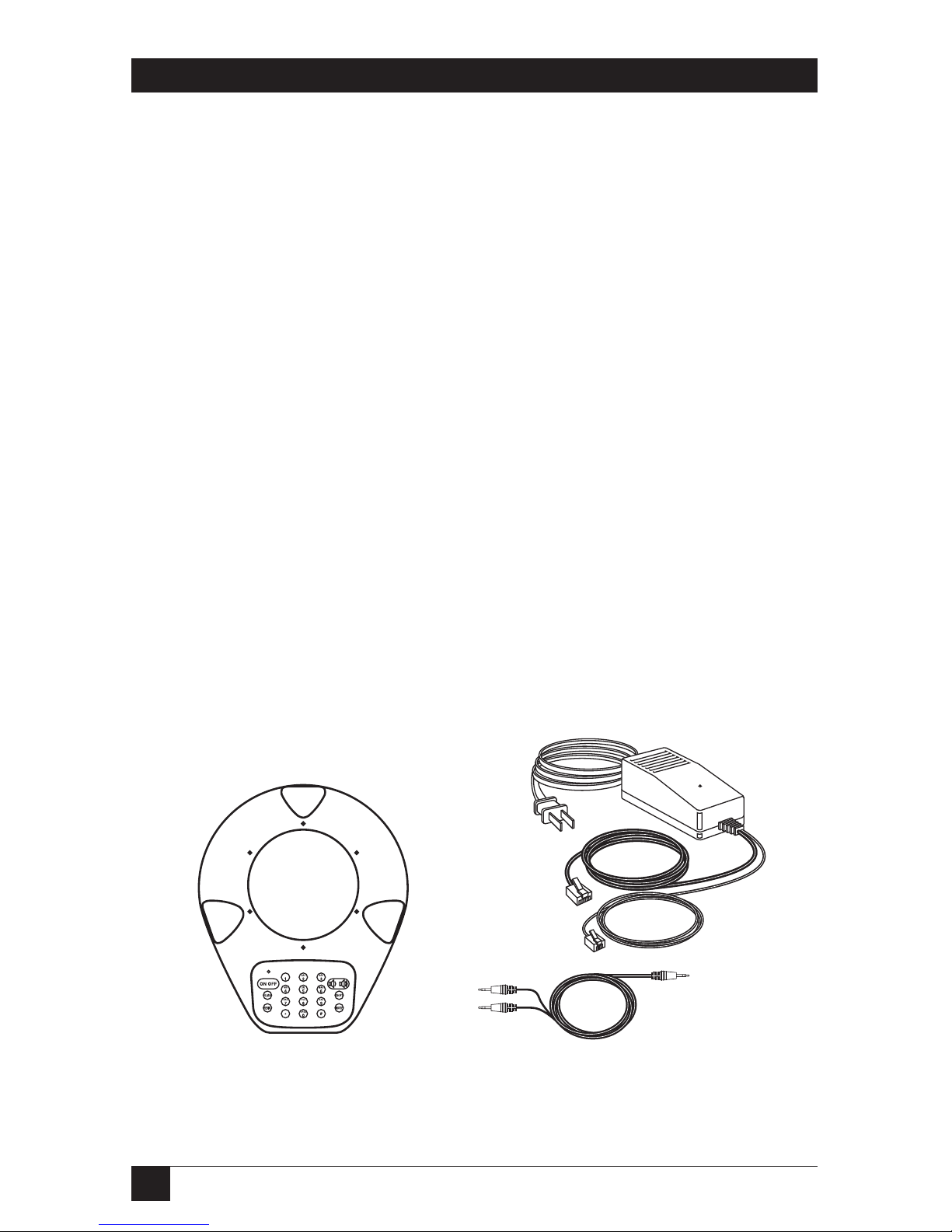
3.1 The Complete Package
Make sure you’ve received everything else that should have been shipped with your
Conference 1 base unit (compare with Figure 3-1):
• Conference 1 power supply with these attached cables:
– 3-foot (1-m) power-input cord (to AC outlet);
– 6-foot (1.8-m) telephone cord with an RJ-11 (6-wire/2-pin) plug (to phone-
system wall jack); and
– 25-foot (7.6-m) base-unit cord with an RJ-45 (8-wire/8-pin) plug.
• 3-foot (1-m) computer sound-card cable. One end has a single mini stereo
plug and the other end has two mini stereo plugs.
• This manual.
If anything’s missing, contact Black Box. However, the manufacturer and their
authorized agents are not responsible for any damage that might have occurred
during shipping; you must make claims directly with the carrier. Inspect your
shipment carefully for obvious signs of damage. If you find any, keep the original
boxes and packing material for inspection by the carrier and contact your carrier
immediately.
Figure 3-1. The Conference 1 and the accessories that ship with it.
Conference 1 phone’s
base unit
Power supply’s
transformer
Sound-
card cable
Power
supply’s
AC-input
cord
Power supply’s
base-unit cord
Power supply’s
telephone cord
Page 12

11
CHAPTER 3: Installation
3.2 Safety Precautions
IMPORTANT NOTE
You should read and understand the warnings and instructions in this
section before you place, install, operate, or maintain the Conference 1.
Take these precautions in order to avoid having problems with your Conference 1:
• Follow all of the instructions and warnings printed on the Conference 1’s
housing.
•Donot put anything on top of the Conference 1, and don’t allow papers or
other objects to obstruct its microphones.
•Donot allow anything to rest on the cords and cables connected to your
Conference 1.
•Donot put your Conference 1 where its cords can be walked on.
• Be careful not to overload wall outlets and extension cords; doing so poses a
risk of fire or electric shock.
• Never push objects of any kind into the openings on your Conference 1’s base
unit or power supply. Objects might touch dangerous voltage points or short
out parts, which could also pose a risk of fire or electric shock.
• Try not to spill liquid of any kind on your Conference 1’s base unit or power
supply. If this ever happens, do not continue to use the Conference 1; use
another phone to call Black Box Technical Support.
• Never try to disassemble your Conference 1’s base unit or power supply. They
don’t contain any user-serviceable parts; opening them can expose you to
dangerous voltages and other risks; and reassembling them incorrectly can
cause equipment damage and/or electric shock the next time the
Conference 1 is operated. Instead, call Black Box Technical Support to
arrange to have the Conference 1 repaired.
• Avoid using your Conference 1 during an electrical storm. There can be a
remote risk of electric shock from lightning.
•Donot use your Conference 1 to report a gas leak. The phone’s buttons route
electrical signals when pressed. These signals can ignite gas fumes, which
could cause a fire or explosion. Instead, report the leak from another location
that’s not involved.
Page 13

12
CONFERENCE 1 PHONE
• When you clean the Conference 1, make sure it’s unplugged from the AC
outlet. Do not use liquid or aerosol cleaners. Instead, use a damp cloth
moistened with water to clean the outside of your Conference 1’s base unit
and power supply.
• It’s conceivable that you might have another power supply whose output cord
is terminated with an RJ-45 plug. However, the power supply that we ship with
the Conference 1 is still the only power supply that you should use with it.
Using a power supply rated for different voltages or currents than the
Conference 1 expects could damage the Conference 1 and attached devices.
3.3 Placement and Preparation
The Conference 1 should be placed on a steady flat surface such as a desk or
tabletop near the center of your conference room. The room shouldn’t be larger
than 20 feet by 20 feet (6 m by 6 m). The Conference 1 should be at least
8" (20 cm) from the edge of the desk or table, at least 18" (46 cm) from any wall,
and within 4 to 6 ft. (1.2 to 1.8 m) of the seats of all people who will be speaking
during phone calls. If there is a sticker on the Conference 1’s speaker, remove it.
Don’t put your Conference 1 on any unstable cart, stand, table, etc. And don’t
place the Conference 1 in damp areas or near places where water can collect. (For
example, don’t place it near a pool, tub, wash basin, or sink, and don’t place it in a
wet basement.) If the Conference 1 falls or gets wet, it could be seriously damaged.
Don’t put your Conference 1 near any noisy equipment or fixtures (ventilation
ducts, loudly humming PCs, etc.). The Conference 1 can reduce, but not
eliminate, background noise.
The Conference 1 is preset for touchtone dialing. If your site’s telephone service
doesn’t include touchtone dialing, slide the PULSE/TONE switch on the bottom
of the Conference 1 to the PULSE position. See Section 4.2.
If you want to connect the Conference 1 to a two-line phone service, you’ll need
a line splitter. These are available at telephone-supply stores. See Section 3.4.5.
If your site’s telephones are on a digital (PBX) system, you’ll need an analog-todigital telephone converter to connect the Conference 1 to one of your site’s
digital phones. We recommend our Conference Linc Up (product code MC117A).
See Section 3.4.6.
If you want to connect the Conference 1 to an audio-recording device, you’ll
need an auxiliary-input cable suitable for the device. Use the cable recommended
for this purpose in the device’s manual. See Section 3.4.7.
Page 14

13
CHAPTER 3: Installation
3.4 Connecting the Conference 1 to Phone Lines and Other Equipment
Installing your Conference 1 is almost is as easy as installing an ordinary telephone.
The following subsections describe how you can connect your Conference 1 to any
of these things:
• A standard telephone line (see Section 3.4.1);
• A computer’s sound card, or other four-wire system (see Sections 3.4.2 and
3.4.3);
• A modem (to share the phone line—see Section 3.4.4);
• Two-line telephone service (see Section 3.4.5);
• A digital telephone system (see Section 3.4.6); or
• An audio-recording device (see Section 3.4.7).
NOTE
These subsections frequently mention the RJ plugs on the cords
attached to the Conference 1’s power supply. One of these, an RJ-11
plug, is a 6-wire type (RJ-12) as opposed to a 4-wire type, but only
carries two pins. The other plug is an 8-wire RJ-45 carrying all 8 pins.
Figure 3-2 shows the side of the Conference 1, including the connectors where
you’ll make these attachments. All connector labels are on the bottom of the unit.
Figure 3-2. The side of the Conference 1.
RJ-45 jack labeled
“LINE” for base-unit cord
from power supply
PULSE/TONE switch (on
bottom, not shown—see
Section 4.2)
3.5-mm mini stereo jack labeled
“PC IN/OUT” for optional cable to
computer’s sound card
RCA jack labeled “REC OUT”
for optional cable to audio-
recording device
Page 15

14
CONFERENCE 1 PHONE
3.4.1 C
ONNECTING TO ASTANDARDTELEPHONELINE
NOTE
Before connecting your Conference 1 to anything you believe to be a
standard phone line—especially at a corporate site with a large number
of phones—verify that you have standard analog phone service. If you
have digital (PBX) telephone service, you’ll need a digital-to-analog
telephone-line converter. See Section 3.4.6.
To connect your Conference 1 to a standard telephone line, take these steps
(referring to Figure 3-3 on the next page):
1. The Conference 1’s power supply has three cords attached to the
transformer. Take the one terminated with an RJ-11 plug and plug it into a
standard telephone-system wall jack.
2. Plug the power supply’s long base-unit cord—the one terminated with an
RJ-45 plug—into the Conference 1 base unit’s RJ-45 jack, labeled LINE on the
bottom of the unit.
3. Plug the power-supply’s AC-input cord into a working standard 120-VAC
electrical outlet. (If the outlet is controlled by a wall switch, turn it on.) The
Conference 1 should play a sequence of self-test sound effects to indicate that
it’s receiving power.
4. Press the ON/OFF button to check for a dial tone. If you hear a dial tone, the
Conference 1 is ready for operation. If you don’t, see Section 5.2.
Page 16

15
CHAPTER 3: Installation
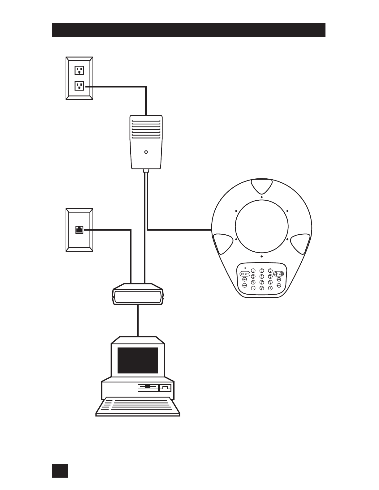
Figure 3-3. Attaching the Conference 1 to a standard phone line.
AC outlet
Phone-system
wall jack
AC-input
cord
Base-unit
cord
Conference 1
base unit
Power supply’s
transformer
Telephone
cord
Page 17
16
CONFERENCE 1 PHONE
3.4.2 C
ONNECTING TO ACOMPUTER’SSOUNDCARD
You can connect your Conference 1 to a computer’s sound card or any other fourwire system that supports full-duplex operation, such as some videoconferencing
equipment and dedicated voice networks. You’ll do this with a sound-card cable
that ships from the factory with the Conference 1. This cable has a single mini
stereo plug at one end and two mini stereo plugs at the other end. Take these
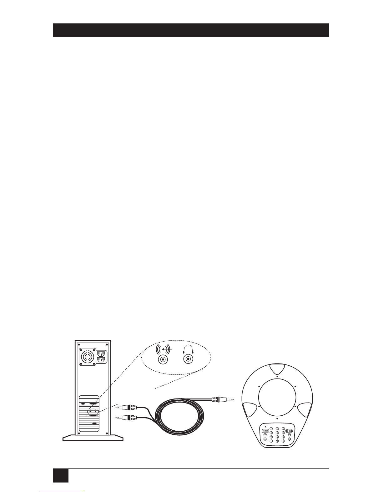
steps, referring to Figure 3-4 (power-supply connections aren’t shown):
1. Plug the sound-card cable’s single-connector end (a black plug) into the PC
IN/OUT jack on your Conference 1 base unit.
2. Plug the cable’s dual-connector end (red and black plugs) into the sound
card or other device: Plug the red plug into the audio LINE OUT jack, and
plug the black plug into the LINE IN jack. These jacks might look like those
shown in Figure 3-4, or the symbols might be different; consult the device’s
manual if you’re not sure which jacks you should use.
3. The Conference 1’s power supply has three cords attached to the
transformer. (You won’t use the one terminated with an RJ-11 plug.) Plug the
power supply’s long base-unit cord—the one terminated with an RJ-45 plug—
into the LINE jack on the Conference 1 base unit.
4. Plug the power-supply’s AC-input cord into a working standard 120-VAC
electrical outlet. (If the outlet is controlled by a wall switch, turn it on.) The
Conference 1 should play a sequence of self-test sound effects.
If you’ve attached the Conference 1 to a computer’s sound card, you’ll need to
turn on the Conference 1 by pressing the SHIFT and ON/OFF buttons at the same
time in order to activate the sound-card connection. If the sound card is installed
in a Windows
®
PC, you’ll need to configure the PC as described in Section 3.4.3.
Figure 3-4. Attaching the Conference 1 to a computer’s sound card.
Sound-
card cable
Black plug
to
PC IN/OUT
Black plug
to LINE IN
LINE IN
LINE OUT
Red plug to
LINE OUT
Conference 1
base unit
Page 18

17
CHAPTER 3: Installation
3.4.3 C
ONFIGURING AWINDOWS
PC’SS
OUNDCARD FORUSEWITH THECONFERENCE
1
If you connect the Conference 1 phone to the sound card of a PC running
Microsoft
®
Windows, you might need to configure it as described in this section.
For the Volume Control adjustments refer to Figure 3-5 on the next page.
To mute external signals with Microsoft Volume Control—Playback:
1. Run the Volume Control program. From the Start menu, follow one of these
paths, depending on your operating system: either “Programs\Accessories\
Entertainment\Volume Control” (Windows 98 and 2000) or “Programs\
Accessories\Multimedia\Volume Control” (Windows 95).
2. Select “MUTE” for “Line In Balance.”
To select external signals with Microsoft Volume Control—Recording:
1. From the “Volume Control” menu, select “Options.”
2. Choose “Properties” from the Options menu.
3. At the “Adjust volume for” option, select “Recording.”
4. At the “Show the following volume controls” option, select “Line In.”
5. Press “OK.”
6. Adjust the “Line In Balance” as necessary.
To use Microsoft NetMeeting
®
:
1. Run the NetMeeting program.
2. Choose “Options” from the Tools menu.
3. Select “Audio” from the Options menu.
4. Deselect (uncheck) “Enable Auto-Gain Control.”
When you’re ready to use the Conference 1 with the PC:
1. Turn off the Conference 1.
2. Power the up the Conference 1 by pressing its SHIFT and ON/OFF buttons at
the same time. The Conference 1 will use the link to the PC’s sound card
until you press ON/OFF again.
Page 19

18
CONFERENCE 1 PHONE
Figure 3-5. The Volume Control window.
Volume
Mute all
Balance:
Volume Control
Options Help
Volume Control
Volume
Mute
Balance:
Wave
Volume
Mute
Balance:
Synth
Volume
Mute
Balance:
CD Audio
Volume
Mute
Balance:
Line In
Page 20

19
CHAPTER 3: Installation
3.4.4 C
ONNECTING TO AMODEM
You can connect your modem and computer to the same single telephone line that
you’re using for your Conference 1. Take the steps listed below, referring to
Figure 3-6 on the next page. If you have any questions about the connectors on, or
cables to use with, your modem or computer, refer to the modem’s or computer’s
manual.
1. Run regular telephone cable from your modem’s telephone-line jack (usually
marked “LINE”) to a standard telephone-system wall jack.
2. If your modem is an external type rather than a modem card, run cable from
its computer port (often marked “COMPUTER” or “DTE”) to the appropriate
port on your computer (usually one of its DB9 or DB25 serial ports).
3. The Conference 1’s power supply has three cords attached to the
transformer. Take the one terminated with an RJ-11 plug and plug it into the
modem’s telephone pass-through jack (often marked “PHONE”).
4. Plug the power supply’s long base-unit cord—the one terminated with an
RJ-45 plug—into the LINE jack on the Conference 1 base unit.
5. Plug the power-supply’s AC-input cord into a working standard 120-VAC
electrical outlet. (If the outlet is controlled by a wall switch, turn it on.) The
Conference 1 should play a sequence of self-test sound effects to indicate that
it’s receiving power.
6. Press the ON/OFF button to check for a dial tone. If you hear a dial tone, the
Conference 1 is ready for operation. If you don’t, see Section 5.2.
Page 21
20
CONFERENCE 1 PHONE
Figure 3-6. Attaching the Conference 1 to a modem (to share its phone line).
AC outlet
Phone-system
wall jack
AC-input
cord
Base-unit
cord
Conference 1
base unit
Power supply’s
transformer
Telephone
cord
Telephone
cable
Modem
Computer
Modem cable
(usually serial)
Page 22

21
CHAPTER 3: Installation
3.4.5 C
ONNECTING TO ATWO-LINETELEPHONESERVICE
Your Conference 1 can operate on one line of a two-line telephone service. To
attach the Conference 1 to such a line, you’ll need a two-line telephone-line
splitter, which routes the two telephone lines—normally expressed on two
different wire pairs of the same jack—into two separate jacks. Line splitters are
available from most telephone-supply stores. Take these steps, referring to
Figure 3-7 on the next page:
1. Plug the line splitter into your two-line telephone jack.
2. The Conference 1’s power supply has three cords attached to the
transformer. Take the one terminated with an RJ-11 plug and plug it into one
of the jacks on the line splitter.
3. Plug the power supply’s long base-unit cord—the one terminated with an
RJ-45 plug—into the LINE jack on the Conference 1 base unit.
4. Plug the power-supply’s AC-input cord into a working standard 120-VAC
electrical outlet. (If the outlet is controlled by a wall switch, turn it on.) The
Conference 1 should play a sequence of self-test sound effects to indicate that
it’s receiving power.
5. Press the ON/OFF button to check for a dial tone. If you hear a dial tone, the
Conference 1 is ready for operation. If you don’t, see Section 5.2.
6. If you want to, plug a standard single-line telephone or other single-line
device into the other jack on the line splitter.
Page 23

22
CONFERENCE 1 PHONE
Figure 3-7. Attaching the Conference 1 to a two-line phone service.
AC outlet
Two-line
wall jack
Line splitter
AC-input
cord
Base-unit
cord
Conference 1
base unit
Power supply’s
transformer
Telephone
cord
Telephone
cable
Single-line phone
(optional)
Page 24

23
CHAPTER 3: Installation
3.4.6 C
ONNECTING TO ADIGITALTELEPHONESYSTEM
Many businesses and other large sites don’t use standard analog phone lines.
Instead, they use digital phone systems that route calls through a PBX (private
branch exchange). If you have to dial “9” or some other digit to reach an outside
line at your site, you probably have a digital system, but check just to make sure. If
you do have digital (PBX) telephone service, you’ll need a digital-to-analog
telephone-line converter in order to use the Conference 1. We offer several of
these converters; at the time of this writing, one that we recommend (and that is
specially designed for use with conference phones) is the Conference Linc Up,
product code MC117A. Be aware that any such converter will degrade the sound
quality of your conversations.
To connect your Conference 1 to a digital telephone system, take these steps,
referring to Figure 3-8 on the next page:
1. Follow the instructions in the digital-to-analog converter’s manual for
connecting the converter to one of the digital telephones connected to your
PBX system. Make sure to use the proper impedance setting. (Most converters
have a four-position switch to match the converter’s impedance with that of
the type of digital phone you’re using. Your converter’s manual should tell
you which setting to use.)
2. The Conference 1’s power supply has three cords attached to the
transformer. Take the one terminated with an RJ-11 plug and plug it into the
jack on the digital-to-analog converter.
3. Plug the power supply’s long base-unit cord—the one terminated with an
RJ-45 plug—into the LINE jack on the Conference 1 base unit.
4. Plug the power-supply’s AC-input cord into a working standard 120-VAC
electrical outlet. (If the outlet is controlled by a wall switch, turn it on.) The
Conference 1 should play a sequence of self-test sound effects to indicate that
it’s receiving power.
5. Lift the digital phone’s handset. Press the Conference 1’s ON/OFF button to
check for a dial tone. If you hear a dial tone, the Conference 1 is ready for
operation. (If you don’t, consult the digital-to-analog converter’s manual; also
see Section 5.2.) Turn the Conference 1 back off and hang up the handset.
To make a call once you’ve installed the Conference 1, lift the digital phone’s
handset and dial the number on the digital phone before you turn on the
Conference 1. After you dial, turn on the Conference 1 by pressing its ON/OFF
button. Leave the digital phone’s handset off the hook during the call. To end the
call, hang up the handset.
Page 25

24
CONFERENCE 1 PHONE
Figure 3-8. Attaching the Conference 1 to a digital (PBX) phone system.
Digital, PBX, or multiline
phone and handset
Digital
phone jack
Conference 1
base unit
Power supply’s
transformer
Base-unit
cord
Telephone
cord
Converter’s power cord
Digital-to-
analog
converter
such as
MC117A
AC-input
cord
AC outlet
Page 26
25
CHAPTER 3: Installation
3.4.7 C
ONNECTING TO ANAUDIO-RECORDINGDEVICE
Your Conference 1 has an RCA®jack so that you can record your conference calls
directly with a tape recorder or other audio-recording device. To connect the
Conference 1 to such a device as shown in Figure 3-9, you’ll need an auxiliary-input
cable suitable for the device (refer to its manual). Plug one end of this cable into
the RCA jack on the Conference 1 labeled (on the bottom of the unit) REC OUT.
Plug the other end into the recording device’s LINE IN jack.
NOTE
Recording phone conversations without the knowledge and consent of
all of the participants is illegal in many areas. Before recording a call
through your Conference 1, be sure that the parties involved are
informed that the call is being recorded. If in doubt, consult legal
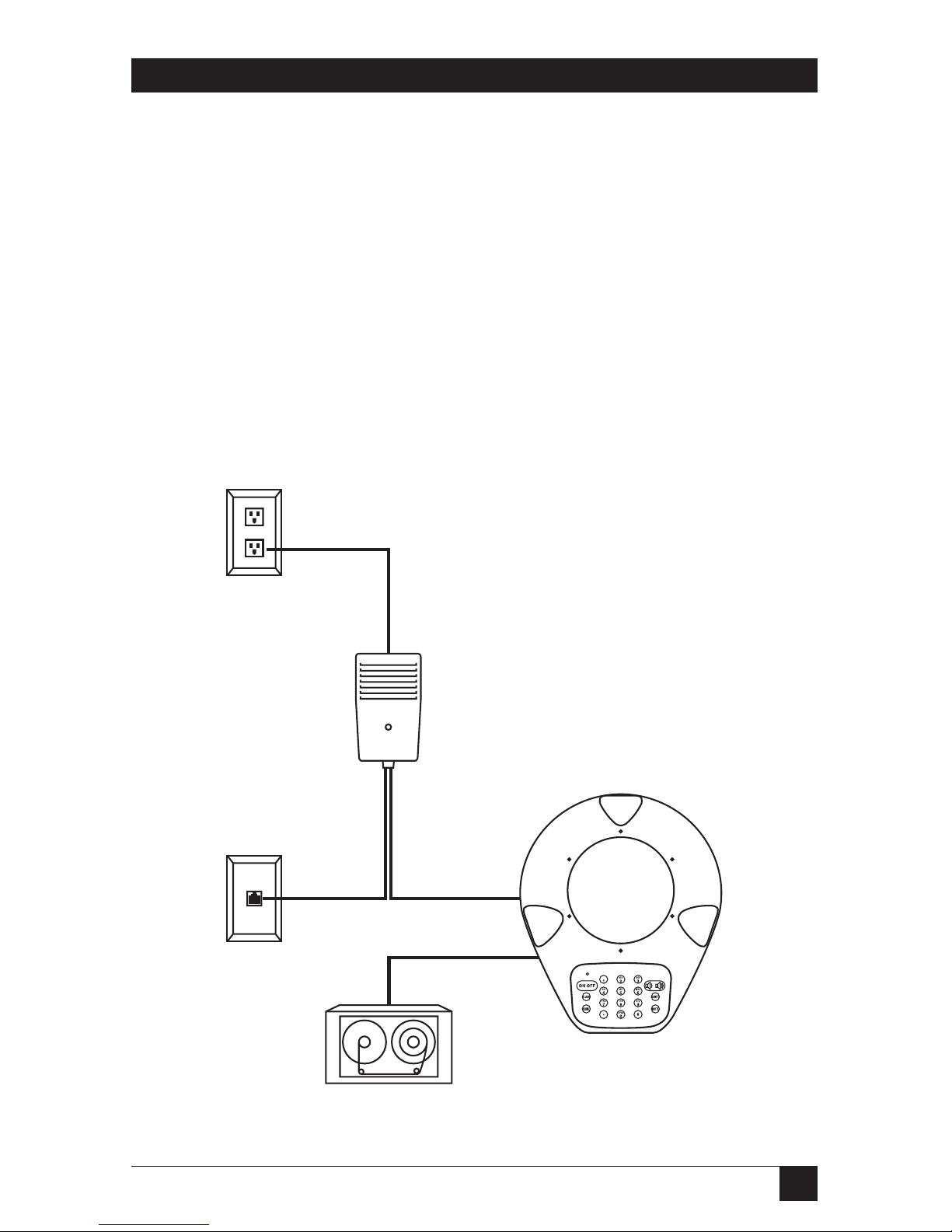
counsel.
Figure 3-9. Attaching the Conference 1 to an audio-recording device.
(Standard phone-system connections are also shown.)
Conference 1
base unit
Audio-recording
device
Power supply’s
transformer
Base-unit
cord
Auxiliary-input
cable
Telephone
cord
AC-input
cord
Phone-
system
wall jack
AC outlet
Page 27
26
CONFERENCE 1 PHONE
4. Operation
Except for the PULSE/TONE switch mentioned in Section 4.2, the buttons on its
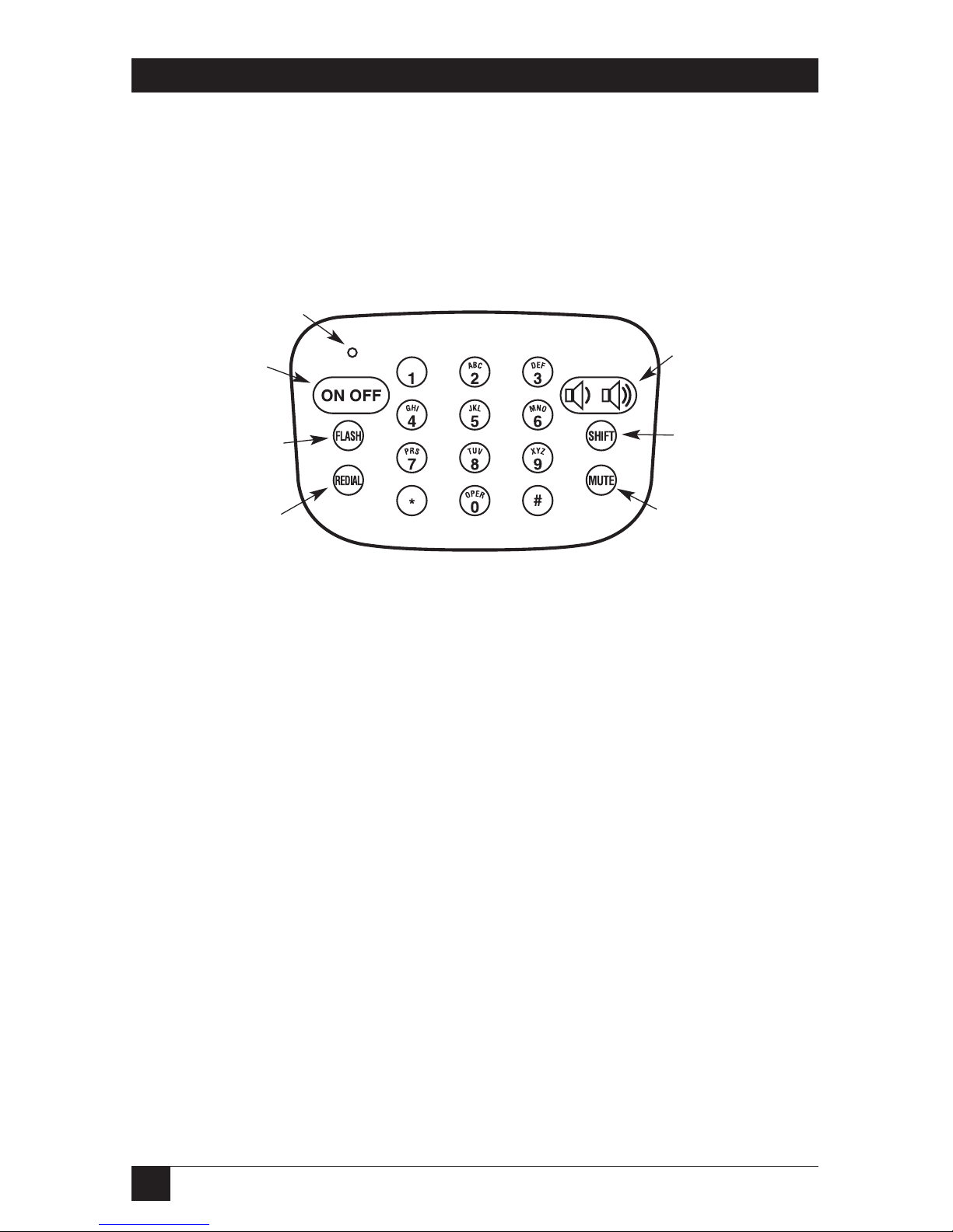
keypad are the Conference 1’s only controls. These are shown in Figure 4-1.
Figure 4-1. The Conference 1’s keypad.
4.1 Echo Cancellation and Noise Reduction
The Conference 1 makes conference calls a lot easier on the parties at the other
end of the line by performing sophisticated echo cancellation that edits the
Conference 1’s speaker output out of the microphone input. Remote parties won’t
have to try to hear what’s being said at your site over the sound of their own voices.
When the Conference 1 performs its initial power-up self-test, it also “samples”
the room it’s in with inaudible sound signals in order to determine the size and
shape of the room for echo-cancellation purposes. If the Conference 1 later detects
that it has been moved, it will resample the room so that it can continue providing
the best possible echo cancellation. (When it does this resampling, it will produce
the same sound effects that it did when it was first powered up.)
In addition to cancelling echoes, the Conference 1 reduces background noise to
provide clearer audio for remote listeners. While this reduction is significant, it’s
not complete; you still need to keep the Conference 1 away from noise sources.
Power
LED
Activates and
deactivates the
Conference 1
Controls any flash
feature(s) you’ve
subscribed to
Redials the last
number called
Turns microphones
on and off
Controls speaker
and ringer volume
Controls optional
connection to
computer’s
sound card
Page 28

27
CHAPTER 4: Operation
4.2 Setting the PULSE/TONE Switch
If you can pick up a phone at your site, dial a number, hear touchtones as you
press the keys, and have the call go through, then you can leave the Conference 1
set to its factory-default tone-dial setting. But if your site uses only rotary phones, or
for whatever other reason does not have touchtone service—that is, if the line
doesn’t seem to recognize or respond to touchtones—you’ll have to move the
PULSE/TONE slide switch on the bottom of the Conference 1 to the PULSE
position. This will cause the Conference 1 to dial with make/break pulses, as a
rotary phone would.
Even if you have to switch the Conference 1 to PULSE for dialing, you can switch
it back to TONE in the middle of a call in order to use a touchtone-recognition
system (for example, to enter a calling-card number, to select options in a tonecontrolled menu, etc.). Just switch to PULSE again before placing your next call.
4.3 Placing a Standard Call
To place a simple point-to-point phone call with the Conference 1 when it’s
connected to a standard phone line, take these steps:
1. Turn on your Conference 1 by pressing its ON/OFF button . The
power LED should come on and you should hear a dial tone. If the LED
doesn’t light and you don’t hear a dial tone, make sure that the
Conference 1’s power supply is plugged in, that its power LED is on, and that
all other connections are secure; also see Section 5.2.
2. Type in the phone number of the party you’re trying to reach. When the call
is answered, the status LEDs around the top of the Conference 1 will become
active; each LED will light in response to sound detected by the
corresponding microphone.
3. When you’re finished with your call, press the ON/OFF button again to hang
up. The power LED and status LEDs will go dark.
You’ll need to use a different procedure to make a call if the Conference 1 is
connected to a digital phone system; see the end of Section 3.4.6.
Page 29

28
CONFERENCE 1 PHONE
4.4 Receiving a Call
To receive a standard point-to-point phone call with the Conference 1, take these
steps:
1. When you hear your Conference 1 ringing and see its power LED flash, you
can answer it by pressing its ON/OFF button . You can then speak to
the caller. The power LED will become solidly lit, and the status LEDs around
the top of the Conference 1 will become active. Each status LED will light in
response to sound detected by the corresponding microphone.
2. When you’re finished with your call, press the ON/OFF button again to hang
up. The power LED and status LEDs will go dark.
4.5 Muting
The Conference 1’s MUTE button controls whether or not the other party
can hear you by turning the Conference 1’s microphones off and on. To mute your
conversation, press the MUTE button during a call to turn the microphones off.
The status LEDs around the top of the Conference 1 will begin flashing about once
a second. To turn the microphones back on, press MUTE again; the status LEDs
will stop flashing.
4.6 Redialing
To redial the last number you called, press the Conference 1’s ON/OFF button
to get a dial tone, then press the REDIAL button .
4.7 Controlling Flash Features
Many local telephone companies offer features such as call transfer, call waiting, or
conference calling that are controlled by quickly “flashing” the phone on and off
hook. To do this, you can use the Conference 1’s FLASH button —it functions
just like the “hook button” that a regular phone’s handset rests on. But the
specifics of when you’ll need to press the button, how long you’ll need to hold it
down, how many times you’ll have to press and release it, etc., are different for
different telephone companies. Please contact them for more information about
any flash features you might have subscribed to.
Page 30

29
CHAPTER 4: Operation
4.8 Making Volume Adjustments
You can control the Conference 1’s speaker or ringer volume by pressing its
volume-control button . Take these steps:
1. If you want to adjust the volume of the sound produced by the Conference 1’s
speakers (callers’ voices, dial tone, etc.), make sure the Conference 1 is turned
on (is off hook, so that dial tone is audible). If you want to adjust the volume
of the sound produced by the Conference 1’s ringer, make sure the
Conference 1 is turned off (is on hook). You can turn the Conference 1 on or
off by pressing the ON/OFF button .
2. To make the chosen volume louder or softer one step at a time, press and release
either the left side (softer) or the right side (louder) of the volume-control
button. The volume of the dial tone (if you’re adjusting the speakers) or of a
sample ring that the Conference 1 emits (if you’re adjusting the ringer) will
change by a discrete amount. Also, some of the status LEDs around the top of
the Conference 1 will begin to flash rapidly. Which LEDs are flashing and
which are dark will depend on the volume level, and this pattern changes as
you change the volume: The status LEDs begin flashing in clockwise order as
the volume gets louder, and go dark in counterclockwise order as the volume
gets softer.)
To run the volume smoothly up or down, press and hold either the left side
(softer) or the right side (louder) of the volume-control button. The volume
will get continuously louder or softer; again, the flashing-vs.-dark pattern of
the status LEDs will change correspondingly.
When you reach the highest or lowest volume setting for the chosen
volume, all LEDs or only one LED will be flashing respectively, and the
volume won’t change any further in that direction.
Page 31

30
CONFERENCE 1 PHONE
5. Maintenance and Troubleshooting
5.1 Cleaning the Conference 1
Under normal conditions, it shouldn’t be necessary to clean the Conference 1 any
more often than other office equipment. When you do so, however, take these
precautions in order to avoid electric shock:
• Follow all warnings and instructions printed on the Conference 1.
• Unplug the Conference 1’s power supply from the AC outlet before you begin
cleaning the base unit or power supply.
•Donot use liquid or aerosol cleaners. Instead, wipe the outside of the
Conference 1’s base unit and power supply with a cloth lightly moistened with
water.
5.2 Things to Check If Something Goes Wrong
If you’re having trouble with your Conference 1, it might not be set up properly, or
equipment connected to it might be improperly configured or malfunctioning.
Here are a few things to check first; if the problem isn’t related to one of these
things, look for your specific problem among those listed on the next page. Make
sure that:
• The Conference 1’s power supply is plugged into a 120-volt electrical outlet,
and its power LED is lit.
• The cord running from the Conference 1’s power supply to its base unit is
securely connected to the base unit.
• The telephone cord from the power supply is securely connected to the
telephone-system wall jack.
• The phone equipment and service being used by the party you’re trying to call
is comparable in quality to the Conference 1 and is working properly.
Page 32

31
CHAPTER 5: Maintenance and Troubleshooting
If you get no dial tone:
• Your Conference 1 might not be set up properly. See Section 3.3.
• The Conference 1 might not be connected to a standard analog phone line. If
your site’s phone system is a digital (PBX) system, you’ll need a digital-toanalog converter. See Section 3.4.6.
You might need to consult with your telecommunications personnel if you get no
dial tone.
If you hear static, background noise, or excessive noise of other kinds:
• You might have a bad connection. Try placing the call again.
• You might have a bad line. Plug a standard phone into the phone-system jack
that Conference 1 is using; if you still get noise, call your telephone company.
• The other party’s room is too noisy. Ask them to locate and quiet the source of
the noise if they can.
If sound from the other location is muffled or echoes:
• The other party might be in a very large room. Ask them to either move closer
to their phone’s microphones or call from a smaller room.
• If you’re using the Conference 1 with a computer’s sound card (see
Section 3.4.2), you might have reversed the connectors on the dual end of the
sound-card cable: Make sure that the red plug is attached to the card’s LINE
OUT jack and the black plug is attached to the LINE IN jack.
• The other party might be using low-quality equipment. Ask them to swap in
better equipment, if possible.
If you can receive calls but not place calls:
• The PULSE/TONE switch on the bottom of the Conference 1 (see
Section 4.2) might be set incorrectly. Fix it.
• Your calls might be going through a digital (PBX) phone system. You’ll need
to dial “9” or some other digit to reach an outside line. See Section 3.4.6.
If none of these suggestions help, please call Black Box Technical Support as
described in the next section.
Page 33

32
CONFERENCE 1 PHONE
5.3 Calling Black Box
If you determine that your Conference 1 is malfunctioning, do not attempt to alter or
repair it. It contains no user-serviceable parts. Contact Black Box Technical Support
at 724-746-5500. In particular, you’ll need to call and arrange for repairs if any of
these things happens:
• The Conference 1 is dropped or otherwise suffers serious impact damage.
• Liquid is spilled into the Conference 1’s base unit or power supply.
• The power-supply cords become broken, damaged, or frayed.
• The Conference 1 fails to operate normally despite the fact that you’ve
carefully followed all of its operating instructions.
• The Conference 1 starts performing badly.
Before you call about any operating problem you haven’t been able to solve, make
a record of the history of the problem. We will be able to provide more efficient
and accurate assistance if you have a complete description, including:
• the nature and duration of the problem;
• when the problem occurs;
• the components involved in the problem;
• any particular application that, when used, appears to create the problem or
make it worse; and
• the results of any testing you’ve already done.
5.4 Shipping and Packaging
If you need to transport or ship your Conference 1:
• Package it carefully. We recommend that you use the original container.
• If you’re shipping the Conference 1 for repair, please include its power supply
and cables. If you’re returning the Conference 1, please include everything
you received with it. Before you ship the Conference 1 back to Black Box for
repair or return, please contact us to get a Return Authorization (RA)
number.
Page 34

33
LEGAL INFORMATION
DISCLAIMER
In no event will the manufacturer or its authorized agents be liable for any special,
indirect, incidental, punitive, or consequential damages of any kind or character,
including but not limited to loss of revenue or profits, failure to realize savings or
other benefits, loss of data or usability, damage to equipment, or claims against the
purchaser by a third party, even if the manufacturer or its agents have been advised
of the possibility of such damages.
The laws of some areas don’t allow the exclusion or limitation of incidental or
consequential damages, so those exclusions in this disclaimer might not apply to
you.
TRADEMARKS USED IN THIS MANUAL
BLACK BOX and the logo are registered trademarks of Black Box
Corporation.
Microsoft, Windows, and NetMeeting are registered trademarks or trademarks of
Microsoft Corporation in the United States and/or other countries.
RCA is a registered trademark of Thomson Consumer Electronics, Inc., a
subsidiary of Thomson multimedia.
Any other trademarks mentioned in this manual are acknowledged to be the property of the
trademark owners.
Page 35

NOTES
Page 36

1000 Park Drive • Lawrence, PA 15055-1018 • 724-746-5500 • Fax 724-746-0746
© Copyright 2001. Black Box Corporation. All rights reserved.
 Loading...