

Page 1
Order toll-free in the U.S.: Call 877-877-BBOX (outside U.S. call 724-746-5500)
FREE technical support 24 hours a day, 7 days a week: Call 724-746-5500 or fax 724-746-0746
Mailing address: Black Box Corporation, 1000 Park Drive, Lawrence, PA 15055-1018
Web site: www.blackbox.com • E-mail: info@blackbox.com
CUSTOMER
SUPPORT
INFORMATION
SEPTEMBER 2005
JHN2021A
JHN2071A
1. Specifications
Connectors: (6) 4-pair 110-type termination blocks,
(6) RJ-45 ports for phone or data (T568B)
Size: 3"H x 6.3"W (7.6 x 16 cm)
Weight: 0.5 lb. (0.2 kg)
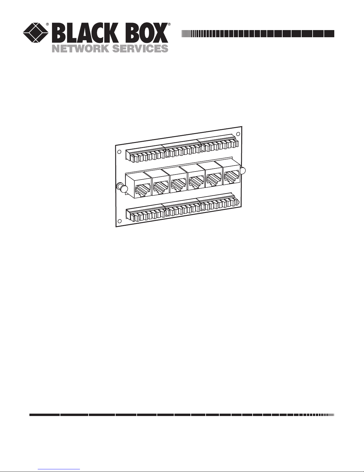
2. Overview
The Pure Home Networking 6-Port CAT5e Data
Module, T568B should be installed in one of the Pure
Home Networking Boxes (JHN1014A, JHN1020A,
JHN1030A, or JHN1040A).
The module supports up to six T568B RJ-45 data
connections; it also has front 110-type punchdown
termination.
3. Installation
3.1 Tools You’ll Need
• Punchdown tool
• UTP stripper
• Wire cutter
3.2 Cable Handling Guidelines
• Do not route telephone cables through the same
cable holes as the AC power cables.
• For safety, separate all telephone cables from
parallel AC power lines by at least 6 inches
(15.2 cm) whenever possible. Avoid kinking the
cable.
• Do not attach cable tie-downs too tightly. The
cable-fastening hardware should not compress
the cable sheath.
• Do not bend the cable sharply. Place the cables
properly in the cable management after passing
them through the holes, since the edges of the
hole can compress or damage the cable sheath.
• When installing an individual module in the Pure
Home Networking Box, place it above or below
the interfacing module (if possible). This will
eliminate excessive cable crossing.
Pure Home Networking
6-Port CAT5e Data Module, T568B
Page 2
1000 Park Drive • Lawrence, PA 15055-1018 • 724-746-5500 • Fax 724-746-0746
© Copyright 2005. Black Box Corporation. All rights reserved.
• For your safety, do not use this or any electrical
product near water (unless it is specifically
designed for wet areas). Do not install wiring
during thunder and lightning storms.
• Use caution when handling or installing any
computer, telephone, video, or electrical devices.
3.3 Attaching a Module to the Module Bracket (JHN2021A Only)
Using the MDU Module Bracket with (2) MDU and
(1) CATV Module Openings, 1 Unit, Full Size
(JHN2030A) is optional. To install it, snap the module
into the bracket. Then press the pushbuttons on the
bracket to lock the module in place. If you choose not to
use the module bracket, go straight to Section 3.4.
3.4 Installing a Module in the Pure Home Networking Box
1. Determine the area for installation.
2. Position the metal tabs on the left side of the
module at a 45-degree angle and slide them into
the rail holes on the Pure Home Networking Box.
3. Insert the metal tabs on the right side of the
module into the rail.
4. Press the button to fasten the module to the Pure
Home Networking Box.
3.5 Removing a Module from the Pure Home Networking Box
1. Press the button and hold it in while pulling the
module from the Pure Home Networking Box.
2. Swing the module out.
3.6 Connecting the Cables to the Data Module
Connect each cable or drop by terminating it to the
designated 110-type termination block.
1. The punchdown blocks are labeled to indicate
where you may terminate each line.
2. Using the appropriate cable stripping tool, strip
approximately 2" (5.1 cm) from the cable jacket.
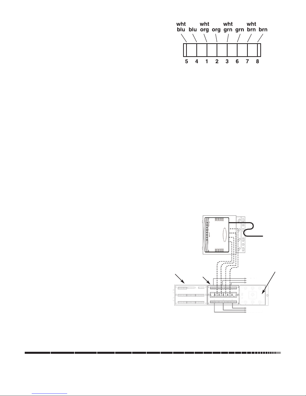
3. Separate the pairs according to color (whiteblue/blue, white-orange/orange, white-green/
green, and white-brown/brown). See Figure 3-1.
Figure 3-1. T568B wire colors.
4. To terminate the connection, place each wire into
the insulation displacement contacts (IDC) by
matching the wire color with the applicable colors
on the terminal block (568B).
NOTE
We recommend untwisting the pairs no more than 0.5"
(1.3 cm) from the termination point.
5. If you are using a 110-type punchdown tool,
position the tool over each wire with the cutting
blade facing outside of the IDC and punch down
firmly.
6. Repeat this process with each wire pair.
We recommend that you use a surge protector (call
Tech Support for details) to protect your module and
phone system from lightning strikes and line surges.
Attach a grounding wire to the ground jumper on the
module. Attach the other end of the wire directly to the
Pure Home Networking Box.
Figure 3-2 shows a sample application.
Figure 3-2. Typical setup.
NOTE
Add data modules as needed.
4-port broadband
router/switch
Any trademarks mentioned in this manual are
acknowledged to be the property of the trademark owners.
6-Port CAT5e Data
Module, T568B
(JHN2021A)
1 x 6-Port Basic
Telephone
Module, T568A
(JHN2023A)
Bidirectional CATV
1 x 6-Port, 1-GHz Video
Splitter Module (JHN2042A)
To outlets #1,
#3, and #5
To outlets #2,
#4, and #6
Internet IN
 Loading...